EP3242009B1 - Moteur à combustion interne doté d'un bloc-moteur et un boîtier de raccordement - Google Patents
Moteur à combustion interne doté d'un bloc-moteur et un boîtier de raccordement Download PDFInfo
- Publication number
- EP3242009B1 EP3242009B1 EP17000589.6A EP17000589A EP3242009B1 EP 3242009 B1 EP3242009 B1 EP 3242009B1 EP 17000589 A EP17000589 A EP 17000589A EP 3242009 B1 EP3242009 B1 EP 3242009B1
- Authority
- EP
- European Patent Office
- Prior art keywords
- crankcase
- internal combustion
- combustion engine
- cover
- gear case
- Prior art date
- Legal status (The legal status is an assumption and is not a legal conclusion. Google has not performed a legal analysis and makes no representation as to the accuracy of the status listed.)
- Active
Links
Images


Classifications
-
- F—MECHANICAL ENGINEERING; LIGHTING; HEATING; WEAPONS; BLASTING
- F02—COMBUSTION ENGINES; HOT-GAS OR COMBUSTION-PRODUCT ENGINE PLANTS
- F02F—CYLINDERS, PISTONS OR CASINGS, FOR COMBUSTION ENGINES; ARRANGEMENTS OF SEALINGS IN COMBUSTION ENGINES
- F02F11/00—Arrangements of sealings in combustion engines
- F02F11/002—Arrangements of sealings in combustion engines involving cylinder heads
-
- F—MECHANICAL ENGINEERING; LIGHTING; HEATING; WEAPONS; BLASTING
- F02—COMBUSTION ENGINES; HOT-GAS OR COMBUSTION-PRODUCT ENGINE PLANTS
- F02F—CYLINDERS, PISTONS OR CASINGS, FOR COMBUSTION ENGINES; ARRANGEMENTS OF SEALINGS IN COMBUSTION ENGINES
- F02F1/00—Cylinders; Cylinder heads
- F02F1/24—Cylinder heads
- F02F1/42—Shape or arrangement of intake or exhaust channels in cylinder heads
- F02F1/4264—Shape or arrangement of intake or exhaust channels in cylinder heads of exhaust channels
-
- F—MECHANICAL ENGINEERING; LIGHTING; HEATING; WEAPONS; BLASTING
- F02—COMBUSTION ENGINES; HOT-GAS OR COMBUSTION-PRODUCT ENGINE PLANTS
- F02F—CYLINDERS, PISTONS OR CASINGS, FOR COMBUSTION ENGINES; ARRANGEMENTS OF SEALINGS IN COMBUSTION ENGINES
- F02F11/00—Arrangements of sealings in combustion engines
-
- F—MECHANICAL ENGINEERING; LIGHTING; HEATING; WEAPONS; BLASTING
- F02—COMBUSTION ENGINES; HOT-GAS OR COMBUSTION-PRODUCT ENGINE PLANTS
- F02F—CYLINDERS, PISTONS OR CASINGS, FOR COMBUSTION ENGINES; ARRANGEMENTS OF SEALINGS IN COMBUSTION ENGINES
- F02F7/00—Casings, e.g. crankcases
- F02F7/0065—Shape of casings for other machine parts and purposes, e.g. utilisation purposes, safety
- F02F7/0073—Adaptations for fitting the engine, e.g. front-plates or bell-housings
- F02F2007/0075—Front covers
-
- F—MECHANICAL ENGINEERING; LIGHTING; HEATING; WEAPONS; BLASTING
- F02—COMBUSTION ENGINES; HOT-GAS OR COMBUSTION-PRODUCT ENGINE PLANTS
- F02F—CYLINDERS, PISTONS OR CASINGS, FOR COMBUSTION ENGINES; ARRANGEMENTS OF SEALINGS IN COMBUSTION ENGINES
- F02F7/00—Casings, e.g. crankcases
- F02F7/0065—Shape of casings for other machine parts and purposes, e.g. utilisation purposes, safety
- F02F7/0073—Adaptations for fitting the engine, e.g. front-plates or bell-housings
- F02F2007/0078—Covers for belt transmissions
Definitions
- the invention relates to an internal combustion engine with a cylinder crankcase and a connection housing.
- crankcase for an internal combustion engine, in which the crankcase is cuboid with a rectangular cross-section, the base of the cuboid approximately corresponding to the lateral projection in the area of the cylinder heads, the crankcase has a chamber which extends from the longitudinal side of the crankcase into the interior of the Crankcase has and the chamber is formed from the two end walls, part of the base and a wall delimiting the crankshaft space.
- the DE 102 20 838 C1 discloses an internal combustion engine with a crankcase, a crankshaft and a camshaft for controlling at least one inlet and outlet valve and an oil pump for delivering lubricating oil to the consumers, with an oil pressure control valve downstream of the oil pump to limit the oil pressure, the valve body of which is held in place by a spring element in Closing direction can be acted upon, the valve body releasing an opening depending on the oil flow rate and / or the oil temperature, which can be connected to the suction side of the oil pump, wherein the crankcase is provided with an inclined parting plane.
- the DE 10 2013 020 944 A1 discloses a crankcase according to the preamble of claim 1.
- the object of the invention is to develop it further.
- crankcase for an internal combustion engine is created, with at least one oil pan flange and a one-piece crankshaft, with at least one end face of the crankcase, on which the wheel drive is arranged, for example, having a machining of the sealing surface towards the timing case cover, which in a Angle of about 4 ° to the vertical with respect to the oil pan flange surface is arranged.
- the advantage here is that the overall length of the crankcase is reduced, which also has an impact on costs.
- crankcase has a cover or a gear case that is releasably attached to the processing of the sealing surface for the gear case cover, which is arranged at an angle of about 4° to the vertical with respect to the oil pan flange surface.
- the length of the motor is crucial in order to keep the devices in which this motor is to be installed compact.
- a criterion for the engine length is the cylinder crankcase and the attachment of the oil pan or its sealing to the cylinder crankcase.
- the gear drive is a co-determinant for the oil sump sealing surface and thus for the engine length.
- the cylinder crankcase (1) has a sealed passage (2) for the gear wheel to the camshaft mounted in the cylinder head.
- the other gears on the crankcase side are covered by a cover/gear case (3).
- the oil pan seal is then made via the crankcase and the cover.
- the seal-converted balcony to the cylinder head can be dispensed with by forming a cover/wheel case that seals both the cylinder head and the oil pan.
- the tolerance problem that arises from this, namely the height of the cylinder crankcase must correspond to the height of this gear case, since on the other hand a sealing crack occurs on one of the two surfaces to be sealed, has not yet been solved.
- crankshaft due to the surrounding edge of the cylinder block, is so short that it has to be equipped with extension components that bridge the passage through the cylinder block wall, in order to establish the connection with e.g. B. gears, flywheel and other attachments.
- the present solution makes it possible to reduce the overall length of the engine without having to accept the disadvantages of the multi-part crankshaft.
- This is achieved by machining the sealing surface for the timing case cover on the side of the cylinder crankcase on which the gear train is arranged, which is at an angle, e.g. B. 4 °, based on the perpendicular to the oil pan sealing surface, takes place that is chosen is that the passage 2 of the gear wheel required to the cylinder head remains sealed and the cylinder crankcase becomes steadily shorter towards the oil pan/oil pan sealing surface 4.
- the sealing counter-contour 5 that is now locally missing on the oil pan is then formed by the gear case cover, which has the complementary angle to the surface of the cylinder crankcase .
- the timing case cover is designed here in one piece 6 or in two pieces 7 with the connection housing.
- the fastening screws and the centering of the connection housing/wheel housing are designed in such a way, advantageously parallel to the longitudinal axis of the crankshaft, that the housing is aligned with the center of the crankshaft.
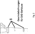
- a gradation of the screw-on slugs, which results from the machining bevel, is possible 8.
- An alternative for the fastening screws is to design the centering hole parallel to the longitudinal axis of the crankshaft and the fastening screws perpendicular to the sealing surface.
- a cylinder crankcase 1 with a passage for the gear wheel to the camshaft 2 is shown.
- a in 1 The cover/gear case 3 (not shown) would rest against the machining of the sealing surface for the gear case cover 4 , with the gear case cover 3 (not shown) having a sealing counter-contour on the gear case cover 5 .
- the timing case covers can be in one piece (6) or in two pieces (7).
- the gradation of the screw-on slugs 8, resulting from the processing slope according to 1 results is in 2 shown.
- the oil pan sealing surface 9 is arranged at the lower end of the crankcase 1 .
- An exhaust gas recirculation (EGR) channel 10 is arranged in the upper area of the crankcase 1 .
- EGR exhaust gas recirculation
- EGR cooler mount 11 At the same level, to the left of EGR duct 10, is the EGR cooler mount 11. Below the EGR duct 10 and the EGR cooler mount 11 is the starter mount 12. According to the invention, it is located diagonally above the EGR duct on one end face of the Crankcase 1 a nose-like Accumulation of material in the area where the gear wheel passes through to the camshaft 13, which is adjacent to the cylinder head gasket surface 14.
- the cover or gear box 3 shows a cylinder crankcase 1 with a passage for the gear wheel to the camshaft 2.
- the cover or gear box 3 is located on the in 1 illustrated processing of the sealing surface to the timing case cover 4, wherein the timing case cover 3 has a sealing counter-contour on the timing case cover 5, which is in the Figures 6a and 6b to be shown.
- the gear case cover can be in one piece 6 or in two pieces 7, which is also in the Figures 6a and 6b you can see.
- the gradation of the screw-on slugs 8, resulting from the processing slope according to 1 results is in 2 shown and is used to connect the cylinder crankcase 1 and gear case cover 3.
- the oil pan sealing surface 9 is arranged at the lower end of the crankcase 1.
- An exhaust gas recirculation (EGR) channel 10 is arranged in the upper area of the crankcase 1 below the cylinder head gasket surface 14 .
- EGR exhaust gas recirculation
- the EGR cooler mount 11 At the same height, to the left of EGR channel 10 and below the cylinder head gasket surface 14, is the EGR cooler mount 11.
- the starter mount 12 Below the EGR channel 10 and the EGR cooler mount 11 is the starter mount 12. Diagonally above the EGR channel on one On the front side of the crankcase 1 there is a nose-like accumulation of material in the area where the gear wheel passes through to the camshaft 13 , which adjoins the cylinder head gasket surface 14 .
- Figure 4a 1 is a plan view of the crankcase 1 according to FIG 1 from below onto the split oil pan sealing surface 9 with the crankshaft 19 mounted (shrunk).
- Figure 4b shows a plan view of the crankcase 1 according to FIG 1 from below onto the closed oil pan sealing surface 9 with a built (screwed) crankshaft 18 revealed.
- figure 5 a represents a plan view of the crankcase according to FIG Figure 4a , b from below onto the oil pan sealing surface 9 with the mounted timing case cover 3, which is in two parts 7, and with a split oil pan flange.
- Figure 5b Figure 1 shows a plan view of the crankcase according to Figure 4a , b from below onto the oil pan sealing surface 9 without the gear case cover 3 mounted and with the oil pan flange 9 closed.
- the gear case cover 3 has a sealing counter-contour on the gear case cover 5, which is in the Figures 6a and 6b to be shown.
- the timing case covers can be in one piece 6 or in two pieces 7 .
Landscapes
- Engineering & Computer Science (AREA)
- Chemical & Material Sciences (AREA)
- Combustion & Propulsion (AREA)
- Mechanical Engineering (AREA)
- General Engineering & Computer Science (AREA)
- Cylinder Crankcases Of Internal Combustion Engines (AREA)
Claims (9)
- Carter de vilebrequin destiné à un moteur à combustion interne et comprenant au moins un flasque de carter d'huile et un vilebrequin monobloc, au moins une face frontale du carter de vilebrequin, au niveau de laquelle est disposée par exemple la transmission par engrenages, comportant un usinage de la surface d'étanchéité menant au couvercle/couvercle de carter d'engrenages, lequel usinage est disposé suivant un angle d'environ 4° par rapport à la verticale par rapport à la surface de flasque de carter d'huile, caractérisé en ce que
une accumulation de matière (13) en forme d'ergot est disposée du côté dirigé vers le carter d'engrenage à peu près dans la zone du passage de l'engrenage à l'arbre à cames (2) du côté garniture d'étanchéité de culasse (14) situé en regard du côté flasque de carter d'huile (9) du carter de vilebrequin. - Carter de vilebrequin destiné à un moteur à combustion interne selon la revendication 1, caractérisé en ce qu'il comporte un couvercle/carter d'engrenages (3) qui est fixé de manière amovible sur l'usinage de la surface d'étanchéité menant au couvercle de carter d'engrenages, qui est disposé suivant un angle d'environ 4° par rapport à la verticale par rapport à la surface de flasque de carter d'huile.
- Carter de vilebrequin destiné à un moteur à combustion interne selon la revendication 1, caractérisé en ce que le couvercle/carter d'engrenages (3) est fixé au carter de vilebrequin au moyen de taraudages 8, ménagés dans le carter de vilebrequin, et de vis correspondantes.
- Carter de vilebrequin destiné à un moteur à combustion interne selon l'une ou plusieurs des revendications précédentes,
caractérisé en ce que le couvercle/carter d'engrenages (3) comporte un usinage correspondant de la surface d'étanchéité suivant un angle d'environ 4° par rapport à la verticale par rapport à la surface de flasque de carter d'huile pour établir une liaison étanche avec la face frontale du carter de vilebrequin (1). - Carter de vilebrequin destiné à un moteur à combustion interne selon l'une ou plusieurs des revendications précédentes,
caractérisé en ce que le carter de vilebrequin (1) comporte au moins un refroidisseur de recirculation de gaz d'échappement intégré (11). - Carter de vilebrequin destiné à un moteur à combustion interne selon l'une ou plusieurs des revendications précédentes,
caractérisé en ce que le carter de vilebrequin (1) comporte au moins un conduit de recirculation de gaz d'échappement (10). - Carter de vilebrequin destiné à un moteur à combustion interne selon l'une ou plusieurs des revendications précédentes,
caractérisé en ce que l'accumulation de matière (13) de type ergot est disposée sensiblement entre la limite supérieure du conduit EGR (10) et le côté garniture d'étanchéité de culasse. - Carter de vilebrequin destiné à un moteur à combustion interne selon l'une ou plusieurs des revendications précédentes,
caractérisé en ce que l'usinage de la surface d'étanchéité menant au couvercle de carter d'engrenages (4), lequel usinage est disposé suivant un angle d'environ 4° par rapport à la verticale par rapport à la surface de flasque de carter d'huile du carter de vilebrequin (9), est disposé entre la surface de flasque de carter d'huile et l'accumulation de matière (13) de type ergot. - Moteur à combustion interne comprenant un carter de vilebrequin de cylindre et un carter de raccordement selon une ou plusieurs des revendications précédentes.
Priority Applications (1)
| Application Number | Priority Date | Filing Date | Title |
|---|---|---|---|
| PL17000589T PL3242009T3 (pl) | 2016-05-04 | 2017-04-07 | Silnik spalinowy z cylindrową skrzynią korbową i obudową przyłączeniową |
Applications Claiming Priority (1)
| Application Number | Priority Date | Filing Date | Title |
|---|---|---|---|
| DE102016005388.7A DE102016005388A1 (de) | 2016-05-04 | 2016-05-04 | Brennkraftmaschine mit einem Zylinderkurbelgehäuse und einem Anschlussgehäuse |
Publications (2)
| Publication Number | Publication Date |
|---|---|
| EP3242009A1 EP3242009A1 (fr) | 2017-11-08 |
| EP3242009B1 true EP3242009B1 (fr) | 2022-01-19 |
Family
ID=58501252
Family Applications (1)
| Application Number | Title | Priority Date | Filing Date |
|---|---|---|---|
| EP17000589.6A Active EP3242009B1 (fr) | 2016-05-04 | 2017-04-07 | Moteur à combustion interne doté d'un bloc-moteur et un boîtier de raccordement |
Country Status (4)
| Country | Link |
|---|---|
| EP (1) | EP3242009B1 (fr) |
| DE (1) | DE102016005388A1 (fr) |
| ES (1) | ES2907653T3 (fr) |
| PL (1) | PL3242009T3 (fr) |
Family Cites Families (9)
| Publication number | Priority date | Publication date | Assignee | Title |
|---|---|---|---|---|
| JPH08151955A (ja) * | 1994-11-29 | 1996-06-11 | Daihatsu Motor Co Ltd | シリンダヘッドのシール構造 |
| JP3633098B2 (ja) * | 1996-04-08 | 2005-03-30 | スズキ株式会社 | 内燃機関のチェーンカバー取付部構造 |
| DE19855562C1 (de) | 1998-12-02 | 2000-05-31 | Mtu Friedrichshafen Gmbh | Kurbelgehäuse |
| DE10220838C1 (de) | 2002-05-08 | 2003-12-18 | Porsche Ag | Brennkraftmaschine |
| DE102004023540A1 (de) * | 2004-05-13 | 2005-12-01 | Deutz Ag | Brennkraftmaschine mit Abgasrückführung |
| DE102004049030B4 (de) * | 2004-10-08 | 2008-09-11 | Audi Ag | Anordnung eines Steuergehäusedeckels |
| DE102005059006A1 (de) * | 2005-12-08 | 2007-06-14 | Deutz Ag | Abgasrückführung einer Brennkraftmaschine |
| DE102013213773A1 (de) * | 2012-07-19 | 2014-01-23 | GM Global Technology Operations, LLC (n.d. Ges. d. Staates Delaware) | Multidirektionale asymmetrische Oberflächen für Gehäuse und Gehäuseabdeckungen sowie Brennkraftmaschinen, die diese aufweisen |
| DE102013020944A1 (de) * | 2013-12-12 | 2014-08-14 | Daimler Ag | Brennkraftmaschine |
-
2016
- 2016-05-04 DE DE102016005388.7A patent/DE102016005388A1/de not_active Ceased
-
2017
- 2017-04-07 ES ES17000589T patent/ES2907653T3/es active Active
- 2017-04-07 EP EP17000589.6A patent/EP3242009B1/fr active Active
- 2017-04-07 PL PL17000589T patent/PL3242009T3/pl unknown
Also Published As
| Publication number | Publication date |
|---|---|
| EP3242009A1 (fr) | 2017-11-08 |
| ES2907653T3 (es) | 2022-04-25 |
| PL3242009T3 (pl) | 2022-05-09 |
| DE102016005388A1 (de) | 2017-11-09 |
Similar Documents
| Publication | Publication Date | Title |
|---|---|---|
| EP0975869B1 (fr) | Systeme d'injection de carburant pour moteur a combustion interne a systeme d'injection par accumulation de pression | |
| DE69909703T2 (de) | Anti-Schaumblech einer Brennkraftmaschine | |
| DE102011008093B4 (de) | Schmieranlage für mit einem Turbolader ausgestatteten Motor | |
| EP0735262B1 (fr) | Bloc-cylindre pour moteur à combustion | |
| DE102011117503A1 (de) | Verbennungsmotor | |
| DE102018116664A1 (de) | Zylinderkopfdeckelstruktur für einen motor | |
| DE3050893C2 (fr) | ||
| DE10033367C2 (de) | Brennkraftmaschine, insbesondere für Motorräder | |
| DE3125077A1 (de) | Zweizylinder-viertakt-boxermotor, insbesondere fahrtwindluftgekuehlt fuer motorraeder | |
| DE4242265C1 (de) | Ventilhaubendeckel | |
| EP0251159B1 (fr) | Conduit de retour pour des gaz de fuite d'une boîte de manivelle | |
| DE19757286A1 (de) | Zylinderkopfaufbau in einer Brennkraftmaschine | |
| EP1799988A1 (fr) | Agencement d'un couvercle de carter de distribution | |
| EP3242009B1 (fr) | Moteur à combustion interne doté d'un bloc-moteur et un boîtier de raccordement | |
| DE60123350T2 (de) | Zylinderkopfdeckel für eine Brennmaschine | |
| DE2547992A1 (de) | Zylinderkopf fuer brennkraftmaschinen mit verdichtungszuendung | |
| DE69519326T2 (de) | Brennkraftmaschine | |
| DE3401266A1 (de) | Vorrichtung zum schutz der zuendeinrichtung an einem mehrzylinder-verbrennungsmotor | |
| DE3604667A1 (de) | Gegossener zylinderkopf fuer eine mehrzylindrige reihen-brennkraftmaschine | |
| DE4406986A1 (de) | Hubkolben-Brennkraftmaschine | |
| DE19548329C2 (de) | Otto-Verbrennungsmotor mit Kraftstoffeinspritzventil | |
| DE19732422C2 (de) | Kettenabdeckung für einen Verbrennungsmotor | |
| DE2843334A1 (de) | Gegenueber der senkrechten geneigter verbrennungsmotor | |
| DE102014101940A1 (de) | Motor mit einem PCV-Abscheidereinlass, der von einer Kopfdichtungsgeometrie abgeschirmt ist | |
| DE19755107B4 (de) | Brennkraftmaschine |
Legal Events
| Date | Code | Title | Description |
|---|---|---|---|
| PUAI | Public reference made under article 153(3) epc to a published international application that has entered the european phase |
Free format text: ORIGINAL CODE: 0009012 |
|
| STAA | Information on the status of an ep patent application or granted ep patent |
Free format text: STATUS: THE APPLICATION HAS BEEN PUBLISHED |
|
| AK | Designated contracting states |
Kind code of ref document: A1 Designated state(s): AL AT BE BG CH CY CZ DE DK EE ES FI FR GB GR HR HU IE IS IT LI LT LU LV MC MK MT NL NO PL PT RO RS SE SI SK SM TR |
|
| AX | Request for extension of the european patent |
Extension state: BA ME |
|
| STAA | Information on the status of an ep patent application or granted ep patent |
Free format text: STATUS: REQUEST FOR EXAMINATION WAS MADE |
|
| 17P | Request for examination filed |
Effective date: 20180508 |
|
| RBV | Designated contracting states (corrected) |
Designated state(s): AL AT BE BG CH CY CZ DE DK EE ES FI FR GB GR HR HU IE IS IT LI LT LU LV MC MK MT NL NO PL PT RO RS SE SI SK SM TR |
|
| GRAP | Despatch of communication of intention to grant a patent |
Free format text: ORIGINAL CODE: EPIDOSNIGR1 |
|
| STAA | Information on the status of an ep patent application or granted ep patent |
Free format text: STATUS: GRANT OF PATENT IS INTENDED |
|
| INTG | Intention to grant announced |
Effective date: 20210825 |
|
| GRAS | Grant fee paid |
Free format text: ORIGINAL CODE: EPIDOSNIGR3 |
|
| GRAA | (expected) grant |
Free format text: ORIGINAL CODE: 0009210 |
|
| STAA | Information on the status of an ep patent application or granted ep patent |
Free format text: STATUS: THE PATENT HAS BEEN GRANTED |
|
| AK | Designated contracting states |
Kind code of ref document: B1 Designated state(s): AL AT BE BG CH CY CZ DE DK EE ES FI FR GB GR HR HU IE IS IT LI LT LU LV MC MK MT NL NO PL PT RO RS SE SI SK SM TR |
|
| REG | Reference to a national code |
Ref country code: GB Ref legal event code: FG4D Free format text: NOT ENGLISH |
|
| REG | Reference to a national code |
Ref country code: CH Ref legal event code: EP |
|
| REG | Reference to a national code |
Ref country code: DE Ref legal event code: R096 Ref document number: 502017012457 Country of ref document: DE |
|
| REG | Reference to a national code |
Ref country code: AT Ref legal event code: REF Ref document number: 1463923 Country of ref document: AT Kind code of ref document: T Effective date: 20220215 |
|
| REG | Reference to a national code |
Ref country code: IE Ref legal event code: FG4D Free format text: LANGUAGE OF EP DOCUMENT: GERMAN |
|
| REG | Reference to a national code |
Ref country code: NL Ref legal event code: FP |
|
| REG | Reference to a national code |
Ref country code: ES Ref legal event code: FG2A Ref document number: 2907653 Country of ref document: ES Kind code of ref document: T3 Effective date: 20220425 |
|
| REG | Reference to a national code |
Ref country code: LT Ref legal event code: MG9D |
|
| PG25 | Lapsed in a contracting state [announced via postgrant information from national office to epo] |
Ref country code: SE Free format text: LAPSE BECAUSE OF FAILURE TO SUBMIT A TRANSLATION OF THE DESCRIPTION OR TO PAY THE FEE WITHIN THE PRESCRIBED TIME-LIMIT Effective date: 20220119 Ref country code: RS Free format text: LAPSE BECAUSE OF FAILURE TO SUBMIT A TRANSLATION OF THE DESCRIPTION OR TO PAY THE FEE WITHIN THE PRESCRIBED TIME-LIMIT Effective date: 20220119 Ref country code: PT Free format text: LAPSE BECAUSE OF FAILURE TO SUBMIT A TRANSLATION OF THE DESCRIPTION OR TO PAY THE FEE WITHIN THE PRESCRIBED TIME-LIMIT Effective date: 20220519 Ref country code: NO Free format text: LAPSE BECAUSE OF FAILURE TO SUBMIT A TRANSLATION OF THE DESCRIPTION OR TO PAY THE FEE WITHIN THE PRESCRIBED TIME-LIMIT Effective date: 20220419 Ref country code: LT Free format text: LAPSE BECAUSE OF FAILURE TO SUBMIT A TRANSLATION OF THE DESCRIPTION OR TO PAY THE FEE WITHIN THE PRESCRIBED TIME-LIMIT Effective date: 20220119 Ref country code: HR Free format text: LAPSE BECAUSE OF FAILURE TO SUBMIT A TRANSLATION OF THE DESCRIPTION OR TO PAY THE FEE WITHIN THE PRESCRIBED TIME-LIMIT Effective date: 20220119 Ref country code: BG Free format text: LAPSE BECAUSE OF FAILURE TO SUBMIT A TRANSLATION OF THE DESCRIPTION OR TO PAY THE FEE WITHIN THE PRESCRIBED TIME-LIMIT Effective date: 20220419 |
|
| PG25 | Lapsed in a contracting state [announced via postgrant information from national office to epo] |
Ref country code: LV Free format text: LAPSE BECAUSE OF FAILURE TO SUBMIT A TRANSLATION OF THE DESCRIPTION OR TO PAY THE FEE WITHIN THE PRESCRIBED TIME-LIMIT Effective date: 20220119 Ref country code: GR Free format text: LAPSE BECAUSE OF FAILURE TO SUBMIT A TRANSLATION OF THE DESCRIPTION OR TO PAY THE FEE WITHIN THE PRESCRIBED TIME-LIMIT Effective date: 20220420 Ref country code: FI Free format text: LAPSE BECAUSE OF FAILURE TO SUBMIT A TRANSLATION OF THE DESCRIPTION OR TO PAY THE FEE WITHIN THE PRESCRIBED TIME-LIMIT Effective date: 20220119 |
|
| PG25 | Lapsed in a contracting state [announced via postgrant information from national office to epo] |
Ref country code: IS Free format text: LAPSE BECAUSE OF FAILURE TO SUBMIT A TRANSLATION OF THE DESCRIPTION OR TO PAY THE FEE WITHIN THE PRESCRIBED TIME-LIMIT Effective date: 20220519 |
|
| REG | Reference to a national code |
Ref country code: DE Ref legal event code: R097 Ref document number: 502017012457 Country of ref document: DE |
|
| PG25 | Lapsed in a contracting state [announced via postgrant information from national office to epo] |
Ref country code: SM Free format text: LAPSE BECAUSE OF FAILURE TO SUBMIT A TRANSLATION OF THE DESCRIPTION OR TO PAY THE FEE WITHIN THE PRESCRIBED TIME-LIMIT Effective date: 20220119 Ref country code: SK Free format text: LAPSE BECAUSE OF FAILURE TO SUBMIT A TRANSLATION OF THE DESCRIPTION OR TO PAY THE FEE WITHIN THE PRESCRIBED TIME-LIMIT Effective date: 20220119 Ref country code: RO Free format text: LAPSE BECAUSE OF FAILURE TO SUBMIT A TRANSLATION OF THE DESCRIPTION OR TO PAY THE FEE WITHIN THE PRESCRIBED TIME-LIMIT Effective date: 20220119 Ref country code: EE Free format text: LAPSE BECAUSE OF FAILURE TO SUBMIT A TRANSLATION OF THE DESCRIPTION OR TO PAY THE FEE WITHIN THE PRESCRIBED TIME-LIMIT Effective date: 20220119 Ref country code: DK Free format text: LAPSE BECAUSE OF FAILURE TO SUBMIT A TRANSLATION OF THE DESCRIPTION OR TO PAY THE FEE WITHIN THE PRESCRIBED TIME-LIMIT Effective date: 20220119 Ref country code: CZ Free format text: LAPSE BECAUSE OF FAILURE TO SUBMIT A TRANSLATION OF THE DESCRIPTION OR TO PAY THE FEE WITHIN THE PRESCRIBED TIME-LIMIT Effective date: 20220119 |
|
| PLBE | No opposition filed within time limit |
Free format text: ORIGINAL CODE: 0009261 |
|
| STAA | Information on the status of an ep patent application or granted ep patent |
Free format text: STATUS: NO OPPOSITION FILED WITHIN TIME LIMIT |
|
| PG25 | Lapsed in a contracting state [announced via postgrant information from national office to epo] |
Ref country code: AL Free format text: LAPSE BECAUSE OF FAILURE TO SUBMIT A TRANSLATION OF THE DESCRIPTION OR TO PAY THE FEE WITHIN THE PRESCRIBED TIME-LIMIT Effective date: 20220119 |
|
| REG | Reference to a national code |
Ref country code: CH Ref legal event code: PL |
|
| 26N | No opposition filed |
Effective date: 20221020 |
|
| REG | Reference to a national code |
Ref country code: BE Ref legal event code: MM Effective date: 20220430 |
|
| PG25 | Lapsed in a contracting state [announced via postgrant information from national office to epo] |
Ref country code: MC Free format text: LAPSE BECAUSE OF FAILURE TO SUBMIT A TRANSLATION OF THE DESCRIPTION OR TO PAY THE FEE WITHIN THE PRESCRIBED TIME-LIMIT Effective date: 20220119 Ref country code: LU Free format text: LAPSE BECAUSE OF NON-PAYMENT OF DUE FEES Effective date: 20220407 Ref country code: LI Free format text: LAPSE BECAUSE OF NON-PAYMENT OF DUE FEES Effective date: 20220430 Ref country code: CH Free format text: LAPSE BECAUSE OF NON-PAYMENT OF DUE FEES Effective date: 20220430 |
|
| PG25 | Lapsed in a contracting state [announced via postgrant information from national office to epo] |
Ref country code: SI Free format text: LAPSE BECAUSE OF FAILURE TO SUBMIT A TRANSLATION OF THE DESCRIPTION OR TO PAY THE FEE WITHIN THE PRESCRIBED TIME-LIMIT Effective date: 20220119 Ref country code: BE Free format text: LAPSE BECAUSE OF NON-PAYMENT OF DUE FEES Effective date: 20220430 |
|
| PG25 | Lapsed in a contracting state [announced via postgrant information from national office to epo] |
Ref country code: IE Free format text: LAPSE BECAUSE OF NON-PAYMENT OF DUE FEES Effective date: 20220407 |
|
| PGFP | Annual fee paid to national office [announced via postgrant information from national office to epo] |
Ref country code: NL Payment date: 20230419 Year of fee payment: 7 |
|
| P01 | Opt-out of the competence of the unified patent court (upc) registered |
Effective date: 20230530 |
|
| PGFP | Annual fee paid to national office [announced via postgrant information from national office to epo] |
Ref country code: AT Payment date: 20230420 Year of fee payment: 7 |
|
| PG25 | Lapsed in a contracting state [announced via postgrant information from national office to epo] |
Ref country code: HU Free format text: LAPSE BECAUSE OF FAILURE TO SUBMIT A TRANSLATION OF THE DESCRIPTION OR TO PAY THE FEE WITHIN THE PRESCRIBED TIME-LIMIT; INVALID AB INITIO Effective date: 20170407 |
|
| PG25 | Lapsed in a contracting state [announced via postgrant information from national office to epo] |
Ref country code: MK Free format text: LAPSE BECAUSE OF FAILURE TO SUBMIT A TRANSLATION OF THE DESCRIPTION OR TO PAY THE FEE WITHIN THE PRESCRIBED TIME-LIMIT Effective date: 20220119 Ref country code: CY Free format text: LAPSE BECAUSE OF FAILURE TO SUBMIT A TRANSLATION OF THE DESCRIPTION OR TO PAY THE FEE WITHIN THE PRESCRIBED TIME-LIMIT Effective date: 20220119 |
|
| PG25 | Lapsed in a contracting state [announced via postgrant information from national office to epo] |
Ref country code: MT Free format text: LAPSE BECAUSE OF FAILURE TO SUBMIT A TRANSLATION OF THE DESCRIPTION OR TO PAY THE FEE WITHIN THE PRESCRIBED TIME-LIMIT Effective date: 20220119 |
|
| REG | Reference to a national code |
Ref country code: NL Ref legal event code: MM Effective date: 20240501 |
|
| REG | Reference to a national code |
Ref country code: AT Ref legal event code: MM01 Ref document number: 1463923 Country of ref document: AT Kind code of ref document: T Effective date: 20240407 |
|
| PG25 | Lapsed in a contracting state [announced via postgrant information from national office to epo] |
Ref country code: NL Free format text: LAPSE BECAUSE OF NON-PAYMENT OF DUE FEES Effective date: 20240501 |
|
| PG25 | Lapsed in a contracting state [announced via postgrant information from national office to epo] |
Ref country code: AT Free format text: LAPSE BECAUSE OF NON-PAYMENT OF DUE FEES Effective date: 20240407 |
|
| PG25 | Lapsed in a contracting state [announced via postgrant information from national office to epo] |
Ref country code: NL Free format text: LAPSE BECAUSE OF NON-PAYMENT OF DUE FEES Effective date: 20240501 Ref country code: AT Free format text: LAPSE BECAUSE OF NON-PAYMENT OF DUE FEES Effective date: 20240407 |
|
| PGFP | Annual fee paid to national office [announced via postgrant information from national office to epo] |
Ref country code: PL Payment date: 20250328 Year of fee payment: 9 |
|
| PGFP | Annual fee paid to national office [announced via postgrant information from national office to epo] |
Ref country code: DE Payment date: 20250528 Year of fee payment: 9 |
|
| PGFP | Annual fee paid to national office [announced via postgrant information from national office to epo] |
Ref country code: ES Payment date: 20250529 Year of fee payment: 9 Ref country code: GB Payment date: 20250423 Year of fee payment: 9 |
|
| PGFP | Annual fee paid to national office [announced via postgrant information from national office to epo] |
Ref country code: IT Payment date: 20250422 Year of fee payment: 9 |
|
| PGFP | Annual fee paid to national office [announced via postgrant information from national office to epo] |
Ref country code: FR Payment date: 20250425 Year of fee payment: 9 |
|
| PGFP | Annual fee paid to national office [announced via postgrant information from national office to epo] |
Ref country code: TR Payment date: 20250402 Year of fee payment: 9 |