EP3242042A2 - Dispositif de fixation pour un élément de mobilier mobile - Google Patents
Dispositif de fixation pour un élément de mobilier mobile Download PDFInfo
- Publication number
- EP3242042A2 EP3242042A2 EP17169477.1A EP17169477A EP3242042A2 EP 3242042 A2 EP3242042 A2 EP 3242042A2 EP 17169477 A EP17169477 A EP 17169477A EP 3242042 A2 EP3242042 A2 EP 3242042A2
- Authority
- EP
- European Patent Office
- Prior art keywords
- side wall
- furniture part
- movable furniture
- front panel
- wall element
- Prior art date
- Legal status (The legal status is an assumption and is not a legal conclusion. Google has not performed a legal analysis and makes no representation as to the accuracy of the status listed.)
- Withdrawn
Links
Images


Classifications
-
- A—HUMAN NECESSITIES
- A47—FURNITURE; DOMESTIC ARTICLES OR APPLIANCES; COFFEE MILLS; SPICE MILLS; SUCTION CLEANERS IN GENERAL
- A47B—TABLES; DESKS; OFFICE FURNITURE; CABINETS; DRAWERS; GENERAL DETAILS OF FURNITURE
- A47B88/00—Drawers for tables, cabinets or like furniture; Guides for drawers
- A47B88/90—Constructional details of drawers
- A47B88/919—Accessories or additional elements for drawers, e.g. drawer lighting
-
- A—HUMAN NECESSITIES
- A47—FURNITURE; DOMESTIC ARTICLES OR APPLIANCES; COFFEE MILLS; SPICE MILLS; SUCTION CLEANERS IN GENERAL
- A47B—TABLES; DESKS; OFFICE FURNITURE; CABINETS; DRAWERS; GENERAL DETAILS OF FURNITURE
- A47B88/00—Drawers for tables, cabinets or like furniture; Guides for drawers
- A47B88/90—Constructional details of drawers
- A47B88/941—Drawers being constructed from two or more parts
-
- F—MECHANICAL ENGINEERING; LIGHTING; HEATING; WEAPONS; BLASTING
- F16—ENGINEERING ELEMENTS AND UNITS; GENERAL MEASURES FOR PRODUCING AND MAINTAINING EFFECTIVE FUNCTIONING OF MACHINES OR INSTALLATIONS; THERMAL INSULATION IN GENERAL
- F16B—DEVICES FOR FASTENING OR SECURING CONSTRUCTIONAL ELEMENTS OR MACHINE PARTS TOGETHER, e.g. NAILS, BOLTS, CIRCLIPS, CLAMPS, CLIPS OR WEDGES; JOINTS OR JOINTING
- F16B12/00—Jointing of furniture or the like, e.g. hidden from exterior
- F16B12/44—Leg joints; Corner joints
- F16B12/46—Non-metal corner connections
-
- A—HUMAN NECESSITIES
- A47—FURNITURE; DOMESTIC ARTICLES OR APPLIANCES; COFFEE MILLS; SPICE MILLS; SUCTION CLEANERS IN GENERAL
- A47B—TABLES; DESKS; OFFICE FURNITURE; CABINETS; DRAWERS; GENERAL DETAILS OF FURNITURE
- A47B88/00—Drawers for tables, cabinets or like furniture; Guides for drawers
- A47B88/90—Constructional details of drawers
- A47B2088/902—Corner connectors for drawers
-
- A—HUMAN NECESSITIES
- A47—FURNITURE; DOMESTIC ARTICLES OR APPLIANCES; COFFEE MILLS; SPICE MILLS; SUCTION CLEANERS IN GENERAL
- A47B—TABLES; DESKS; OFFICE FURNITURE; CABINETS; DRAWERS; GENERAL DETAILS OF FURNITURE
- A47B2230/00—Furniture jointing; Furniture with such jointing
- A47B2230/02—Assembly systems with separate fixing devices on each corner wall and a common corner joining element
-
- F—MECHANICAL ENGINEERING; LIGHTING; HEATING; WEAPONS; BLASTING
- F16—ENGINEERING ELEMENTS AND UNITS; GENERAL MEASURES FOR PRODUCING AND MAINTAINING EFFECTIVE FUNCTIONING OF MACHINES OR INSTALLATIONS; THERMAL INSULATION IN GENERAL
- F16B—DEVICES FOR FASTENING OR SECURING CONSTRUCTIONAL ELEMENTS OR MACHINE PARTS TOGETHER, e.g. NAILS, BOLTS, CIRCLIPS, CLAMPS, CLIPS OR WEDGES; JOINTS OR JOINTING
- F16B12/00—Jointing of furniture or the like, e.g. hidden from exterior
- F16B12/44—Leg joints; Corner joints
- F16B12/46—Non-metal corner connections
- F16B2012/466—Non-metal corner connections using mortise and tenon joints
-
- F—MECHANICAL ENGINEERING; LIGHTING; HEATING; WEAPONS; BLASTING
- F16—ENGINEERING ELEMENTS AND UNITS; GENERAL MEASURES FOR PRODUCING AND MAINTAINING EFFECTIVE FUNCTIONING OF MACHINES OR INSTALLATIONS; THERMAL INSULATION IN GENERAL
- F16B—DEVICES FOR FASTENING OR SECURING CONSTRUCTIONAL ELEMENTS OR MACHINE PARTS TOGETHER, e.g. NAILS, BOLTS, CIRCLIPS, CLAMPS, CLIPS OR WEDGES; JOINTS OR JOINTING
- F16B5/00—Joining sheets or plates, e.g. panels, to one another or to strips or bars parallel to them
- F16B5/0004—Joining sheets, plates or panels in abutting relationship
- F16B5/0032—Joining sheets, plates or panels in abutting relationship by moving the sheets, plates, or panels or the interlocking key parallel to the abutting edge
- F16B5/0052—Joining sheets, plates or panels in abutting relationship by moving the sheets, plates, or panels or the interlocking key parallel to the abutting edge the interlocking key acting as a dovetail-type key
Definitions
- the invention relates to a device for a movable furniture part of a piece of furniture, as well as a piece of furniture with such a device.
- the drawer comprises side wall elements made of glass, which are held by a clamping device on the drawer in the assembled state.
- the disadvantage of this is that the side wall elements can be released from the clamping device, or that the side wall elements are arranged on the drawer so that when a movement of the drawer for a user comparatively unpleasant noise, for example, a clicking or hitting can be heard.
- the invention is based on the object to provide an alternative device for a movable furniture part.
- the invention relates to a device for a movable furniture part of a piece of furniture, in particular for a drawer, wherein the movable furniture part is linearly movable relative to the furniture and wherein the movable furniture part has a side wall element made of glass.
- the movable furniture part is advantageously designed as a drawer, wherein the drawer comprises a bottom element and perpendicular thereto formed two oppositely disposed side wall elements, a front wall or front panel and a rear wall.
- the side wall element of one of the further floor and / or wall elements of the movable furniture part is formed of glass, in particular that all elements are made of glass.
- the glass is an inorganic or mineral glass. It is also conceivable that the glass is Plexiglas.
- the bottom element is advantageously designed as a one-piece and continuous plate element.
- the bottom element extends laterally to an outermost boundary surface of the movable furniture part.
- the side wall element forms a particular inner side surface of the drawer, in particular no extra frame is provided.
- the front panel is for a user, e.g. not transparent.
- the front panel is then e.g. made of wood, metal, opaque plastic, opaque glass or a combination of materials. If the movable furniture part designed as an inner drawer, the front panel can be transparent to a user.
- the side wall element is advantageously designed plate-like. It is also conceivable that the side wall element is made of a transparent mineral or inorganic glass, in particular the side wall element is at least partially permeable or transparent to visible light.
- the sidewall member comprises two or more, in particular similar, e.g. plate-like side wall parts.
- Both the side wall element and the side wall parts are advantageously designed as particularly continuous, flat, elongated cuboid elements.
- the side wall element along a longitudinal axis and / or perpendicular to the longitudinal axis is divided into side wall parts.
- At least one sidewall portion is e.g. made of glass. If the side wall element comprises a plurality of side wall parts, then it is conceivable that a side wall part made of wood, metal, plastic and / or fabric is formed. Advantageously, the side wall parts are joined together, in particular glued.
- the movable furniture part on a support strut for example made of metal, in particular aluminum.
- the support strut serves as an element that stabilizes the movable furniture part.
- the support strut can be configured from a U-profile or a square element.
- the support strut is shaped like a frame and, for example, from a view from above in particular rectangular. It is conceivable that the bottom element is arranged with its bottom underside on the support strut or the frame.
- the frame and the floor element have identical external dimensions.
- the side wall element is permanently connected to the bottom element as well as to the frame and / or the support strut by means of a joining method.
- the frame and / or the support strut is configured to arrange a pull-out rail for the movable furniture part.
- the sidewall member may have an approximately curved contour along a longitudinal axis or a curved edge. It is also conceivable that the contour or the edge is formed approximately zigzag.
- the side wall element is fixed in position by joining with the bottom element and / or the rear wall and / or the front panel, in particular undetachably connected.
- the device comprises a cuboid, elongated support member, wherein the support member in the arranged state on the movable furniture part in a corner region of the bottom member is upstanding, wherein the support member is configured such that in mounted state of the movable furniture part, the side wall member is supported in an outward direction on the support member and in an opposite direction, inwardly of the front panel and / or the rear wall.
- the side wall element is arranged, for example, in a form-fitting manner, in particular in a positionally fixed manner, between the support element and the front panel and / or the rear wall, advantageously clamped. It is also conceivable in that the side wall element can be inserted from above, with its lower, long narrow side, in the direction of an upper side of the floor element between the support element and the front panel and / or the rear wall.
- the upper side of the floor element is present opposite the underside of the floor element on the floor element and forms a shoulder inner surface.
- the lower, long narrow side of the side wall element is formed, for example, parallel to the longitudinal axis of the side wall element.
- a width of a short narrow side of the side wall member is shorter than a perpendicular distance of two oppositely formed large side surfaces of the side wall member.
- an edge of the short narrow side is chamfered and / or formed as a concave groove or depression.
- two oppositely arranged edges of the short narrow side are chamfered and / or formed as a concave groove or depression.
- three edges of the short narrow side are chamfered and / or formed as a concave groove or depression.
- the edge is preferably aligned perpendicular to the longitudinal axis of the side wall element.
- a large side surface of the side wall member advantageously forms the inner or outer drawer side surface.
- the short narrow side of the side wall element is in particular aligned perpendicular to a long narrow side of the side wall element and / or to a large side surface of the side wall element.
- a limitation on the side wall element fitting present in the arranged state of the front wall and / or the rear wall of the drawer.
- the device comprises a cuboidal, elongated support member, wherein the support member in the arranged state on the movable furniture part in a corner region of the bottom element is upwardly projecting, wherein the support element is configured such that in the assembled state of the movable furniture part the Front wall and / or the rear wall is supported in an outward direction on the support member and in an opposite direction, inwardly on the side wall member.
- the support element in the arranged state on the movable furniture part, has a first side surface of the support element facing the side wall element, wherein the first side surface comprises a holding member projecting from the side surface in the direction of the side wall element.
- the holding member is formed, for example, like a strip and in particular along an edge of the first side surface and e.g. present parallel to a longitudinal axis of the support member on the first side surface.
- the holding member may be formed, for example, bevelled along its longitudinal axis.
- the support element advantageously comprises two, three or four holding members.
- the support element is cuboid, and comprises six side surfaces, wherein it is provided with a side surface, e.g. is arranged on the bottom element of the movable furniture part
- first retaining member is provided on the first side surface of the support member and a second retaining member is provided on a second side surface support member.
- the two side surfaces are in an angle to each other. It is also conceivable that the two retaining member are present opposite one another on the support element.
- a holding member is configured such that it is formed on a third, fourth and / or fifth side surface of the support element and the side surface advantageously completely covered.
- the holding member forms in this case, for example, a part of an outer side of the movable furniture part.
- the holding member may be configured such that it is provided on the third, fourth and / or fifth side surface of the support member such that, on the side wall element, the front wall and / or the rear wall facing first or second side surface, in the direction of Sidewall element, the front wall and / or the rear wall protrudes.
- the first or second side surfaces is advantageously formed at an angle to the third, fourth or fifth side surface.
- the holding member is provided on the third, fourth or fifth side surface, so that the holding member projects over a short narrow side of the support member, in particular up or in the direction of the side wall element, the front wall and / or the rear wall in the arranged state on the movable furniture part.
- the short narrow side is formed in the arranged state of the support member on the movable furniture part in an upper region of the movable furniture part.
- the device forms an outer side wall part on a narrow side of the side wall element in the mounted state of the movable furniture part.
- the device may be made of wood, metal, glass, plastic and / or a combination of materials.
- the side wall element is, for example, plugged onto the device and / or clamped and / or joined to the device.
- the side wall element is through the Device releasably connected to the front panel and / or the rear wall. It is also conceivable that the side wall element is permanently connected by the device with the front panel and / or the rear wall, for example by joining.
- Joining is understood in particular as bonding, soldering, laser welding, laser melting, ultrasonic welding and / or ultrasonic melting.
- the device is, for example, via an adhesive, e.g. an adhesive tape inextricably linked to the sidewall element.
- the device comprises a mounting member, and the mounting member can be arranged on a narrow side surface of the side wall member, wherein the narrow side surface in the assembled state of the movable furniture part of the front panel and / or the rear wall facing, wherein the Side wall element arranged mounting member is used in a mounting operation from a direction from above into a matching to an outer contour of the mounting member particularly concave ausgestaltetes mounting element on the movable furniture part, so that the side wall element is fixedly mounted in the assembled state on the furniture part.
- the mounting element forms e.g. a fit for the mounting member, this is the side wall element in particular form-fitting manner to the movable furniture part can be arranged.
- the mounting element, the movable furniture part is, for example, on the front panel and / or the rear wall or on a corner post, e.g. formed the support member of the movable furniture part.
- the front panel and / or the rear wall may comprise the mounting element.
- the mounting element is part of the device and arranged on the front panel and / or the rear wall and / or the Ecksteher, in particular positionally fixed, for example by joining.
- the mounting member advantageously has a recess which forms an undercut.
- the undercut has, e.g. from a view from above onto a narrow side of the mounted front panel and / or e.g. on a narrow side of the mounted rear wall, a contour which resembles, for example, a recording of a puzzle piece.
- the mounting member is designed, for example, strip-like. It is also conceivable that from a view from above on the mounting member, e.g. parallel to a longitudinal axis of the mounting member, the mounting member has a silhouette, which is similar to a convex shape, such as a tooth, a puzzle piece. Wherein the convex shape of the outer contour of the mounting member is in particular positively inserted into the concave contour of the mounting element.
- the device has a connecting member, a bolt-shaped connecting element and a fork-like part, wherein the connecting member can be arranged on a narrow side surface of the side wall element, wherein the narrow side surface in the assembled state of the movable furniture part of the front panel and / or the rear wall facing, wherein the bolt-shaped connecting element in the assembled state of the movable furniture part in the direction of the side wall element projecting on a front panel and / or a rear wall of the movable furniture part is formed, wherein the device is configured to, in the mounted state of the movable furniture part, the front panel and / or the rear wall and the side wall element releasably connect to each other, wherein the bolt-shaped connecting element with the fork-like part on the connecting member in the assembled state of the movable furniture part is engaged behind, so that the side wall element is in particular firmly connected to the front panel and / or the rear wall.
- the bolt-shaped connecting element is advantageously engaged behind from a mounting direction from above with the fork-like part of the device on the connecting member.
- the connecting member is, for example, strip-like, designed for example as an L-shaped or U-shaped profile.
- the connecting member is provided on the narrow side surface of the side wall member projecting on the side wall member.
- the connecting member is joined, for example, to the narrow side surface. This is e.g. a clearance between the narrow side surface of the side wall member and a portion of the connecting member is formed, in which in particular the fork-like part can be inserted.
- the portion of the connecting member is formed as a short side of the L-shaped or U-shaped profile, wherein the short side of the profile is advantageously aligned parallel to the narrow side surface of the side wall member.
- the fork-like part comprises a nail-shaped head, which forms an outside of the movable furniture part, in particular an upper side in the arranged state on the movable furniture part.
- a nail-shaped head which forms an outside of the movable furniture part, in particular an upper side in the arranged state on the movable furniture part.
- one side of the nail-shaped head is arranged in the arranged state on the movable furniture part flush with a length, narrow side surface of the side wall element.
- the device comprises an electrically conductive member.
- the electrically conductive member may be formed on the device such that the side wall element or a component arranged on the side wall element can be supplied with electrical energy.
- the electrically conductive member forms an electrically conductive contact with the side wall element.
- the electrically conductive member is formed on the device such that one arranged on the front panel electrical component, for example a light source, for example an LED or an LED strip starting from the side wall element can be supplied with electrical energy.
- the device is made of a metal electrically conductive.
- a light source is arranged along a narrow side surface of the side wall element, in particular the light source is present on the narrow side surface, e.g. inserted so that the light source does not protrude from the narrow side surface.
- the electrically conductive member is formed for example as a cable and / or as an electrical conductor and / or as an electrically conductive contact.
- the device is designed to be arranged on a narrow side surface of the side wall member in particular projecting, wherein the device, in the arranged state on the side wall element from a view of the narrow side surface does not surmount an edge of the side wall element.
- the front panel and / or the rear wall of the movable furniture part has an undercut, wherein the device is configured and arranged on the side wall element, that the device from above into the undercut of the front panel and / or the rear wall can be inserted and / or inserted is, wherein the side wall element in the inserted state is in a functional position on the movable furniture part.
- the device is designed like a clip and, for example, can be attached to a narrow side of the side wall element, for example attachable. Wherein the device in the assembled state connects the side wall element and the front panel and / or the rear wall by clamping.
- the device is designed such that it engages around an upper narrow side of the front panel and / or the rear wall and connects the side wall element with the front panel and / or the rear wall by clamping.
- the device has an L-shaped or U-shaped hook, which is attached to the side wall element such that the hook engages over an upper narrow side of the front panel and / or the rear wall.
- the side wall element is attached to the front panel and / or the rear wall on the movable furniture part, for example, inserted from above.
- the device comprises a pin and the pin in the arranged state on the side wall element on a narrow side surface is arranged projecting, wherein the pin is intended toêtstecken a mounting arrangement of the device, wherein the mounting arrangement, the side wall element with the front panel and / or the back wall connects.
- a side wall element of the movable furniture part comprises a bore, so that the device can be inserted into the bore, wherein the side wall element and the front panel and / or the rear wall can be connected by means of the device.
- the pin is mounted on the front wall and / or rear wall and inserted into the bore of the side wall member.
- FIG. 1 shows a furniture according to the invention 1.
- the furniture 1 comprises a furniture body 2 and a, arranged on each opposite the furniture body 2 extracts 3, 4, movably guided drawer 5.
- the drawer 5 has a front wall 6, a rear wall 7, side walls 8, 9 and a bottom element 10.
- the bottom element 10 is mounted on support struts 11.
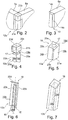
- a device is configured as a corner post 12a, 12b.
- the corner post 12a, 12b is in the arranged state on the drawer 5, for example in a corner region of the drawer 5, for example, between the side wall 8a and the rear wall 7a formed ( FIG. 2 ).
- the side wall 8a may be formed, for example, beveled on a short narrow side 13 at edges 14a, 14b ( FIG. 3 ).
- the side wall 8a is arranged with its short narrow side 13, for example, pending on a first side surface 19a on the corner post 12a, 12b ( FIG. 2 ).
- the two training variants in common is that the corner posts 12a, 12b, for example, cuboid, rod-like and in the assembled state on the drawer 5 with a longitudinal axis L perpendicular to the bottom element 10 of the drawer 5 upwardly projecting on the bottom element 10 and / or on the support strut 11th is attached, for example, is screwed.
- the corner post 12b can have an external thread 16 on a short narrow side 15, by means of which the corner post 12b can be screwed onto the bottom element 10 and / or the support strut 11 (FIG. FIG. 6 ).
- the corner post 12a has a bore 17 parallel to its longitudinal axis L.
- the bore 17 may be formed as an elongated hole and penetrate the Ecksteher 12 a in particular completely.
- the bore 17 includes, for example, an internal thread, by means of which the Ecksteher 12 a can be connected to the bottom element 10 and / or the support strut 11 ( FIG. 5 ).
- the corner post 12a, 12b is advantageously arranged on the drawer 5 such that it is provided with side surfaces 19a, 19b e.g. pending on the side wall 8a and the rear wall 7a is arranged.
- Side surfaces 19c, 19d form, in the arranged state of the Eckstehers 12a, 12b on the drawer 5, in particular outer surfaces of the drawer. 5
- the corner post 12a, 12b may include a holding member 20c, 20d, which is provided on a further edge region of the side surface 19a, 19b projecting from the side surface 19a, 19b, wherein the holding member 20c, 20d in the arranged state of the corner post 19a, 19b on the Drawer 5 advantageously the side wall 8a and the rear wall 7a engages over at least a portion.
- the edge region of the side surface 19a, 19b, in particular the holding member 20a to 20d advantageously forms a partial region of an outer surface of the drawer 5.
- the corner post 12a can advantageously be designed in two parts ( FIG. 4 ).
- the corner post 12a may comprise a first elongated rod-shaped element 21a and a second cube-shaped element 21b. Both elements 21a, 21b advantageously have holding members 20a, 20b. If the corner post 12a is designed in two parts, the first element 21a can be fastened to the bottom element 10 in a first assembly operation, the side wall 8, 8a, 9, the front wall 6 and the rear wall 7, 7a can be arranged on the drawer 5 in a subsequent assembly process and in a final Assembly process, the second, cube-shaped element 21b mounted on the first element 21a, for example screwed to the bore 17.
- corner post 12b is configured in one piece, then the side wall 8, 8a, 9, the front wall 6 and the rear wall 7, 7a are arranged on the drawer 5 during assembly of the drawer 5, and then the corner post 12b is advantageously placed between the side wall 8 from above , 8a, 9 and the front wall 6 or the rear wall 7, 7a inserted and fixed to the drawer 5.
- corner post 12b on a side surface 19a, 19b have a strip-like recess 22a, 22b.
- an LED strip 23a, 23b can be introduced ( FIGS. 6, 7 ).
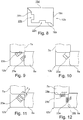
- FIGS. 8 to 12 show a corner post 12b viewed in a cross section from above parallel to its longitudinal axis L, wherein in the FIGS. 9 to 12 arranged wall elements 7a, 8a are shown.
- the LED strip 23a, 23b can be arranged in the recess 22a, 22b in such a way that it has different emission directions and / or a different emission characteristic ( FIGS. 9 to 12 ).
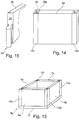
- a device according to the invention is designed, for example, as a bent or shaped sheet-metal element 24.
- the bent sheet metal element 24 viewed parallel to a longitudinal axis viewed a convex, in particular puzzle-shaped contour.
- the bent sheet metal element 24 is at an opposite end to the convex contour, fixed to a narrow side surface 25 of the side wall 9a, for example glued ( FIG. 15 ).
- Eckstehern 12 c to 12 f which arranged, for example, in the corner regions of a drawer according to the invention 5 a are, for example, a front wall 6a and a rear wall 7b attached ( FIGS. 13, 14 ).
- a groove 26 is formed on a side surface 19e of the corner stool 12c, which is formed opposite to the drawer 5a of the side surface 25 of the side wall 9a in the arranged state.
- the groove 26 advantageously extends parallel to a longitudinal axis of the Eckstehers 12c, in particular along a length of the side surface 19e of the Ecksteher 12c.
- the groove 26 has, for example, from a view from above, parallel to the longitudinal axis L of the Eckstehers 12c a concave outline with, for example, an undercut.
- the concave outline is designed, for example, in the form of a puzzle contour.
- the convex contour of the sheet metal element 24 is designed to match the concave contour of the corner post 12c. If, for example, the concave contour does not include an undercut, the sheet metal element 24 and the concave contour are advantageously joined together in the arranged state.
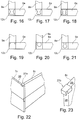
- FIGS. 16 to 21 show the corner post 12c and the front wall 6a and the side wall 9a in a cross section viewed from above parallel to the longitudinal axis L of the corner post 12c.
- the FIGS. 16 to 21 Further different conceivable convex contours of the sheet metal element 24 or concave outlines of the corner stirrer 12c can be seen.
- the convex contours and concave outlines in common is advantageously that they are designed to match each other, and that the concave outline, for example, includes an undercut.
- a device according to the invention is designed as a hook-shaped holding element 27a, 27b ( FIGS. 22, 23 ).
- the holding element 27a, 27b may be attached at a first end to a narrow side 28, 29 of a side wall 8c, in particular adhesively bonded.
- the holding element 27a, 27b may, viewed from a lateral view of the holding element 27a, 27b, have a U-shape, in particular be hook-shaped.
- the side wall 8c is advantageously fixed in a fixed position on the movable furniture part in a direction parallel to the upper side 30 of the rear wall 7c.
- a device according to the invention comprises a nail 31, a connecting member 32 and a bolt 33.
- FIG. 24 shows a cross section through a front wall 6b, the device and a side wall 9b parallel to a longitudinal axis of the side wall 9b.
- FIG. 25 shows the vertical section through the front wall 6b, the device and the side wall 9b in the direction of the bottom element 10.
- the nail 31 has a head 34 and a fork-like securing element 35 (FIG. FIG. 26 ).
- the connecting member 32 is formed for example as a U-shaped profile and, for example, attached to a narrow side surface 36 of a side wall 9b, that the profile with the side surface 36 includes a channel-like cavity ( FIGS. 24, 25 ).
- the connecting member 32 further comprises an opening 37 through which in the arranged state of the side wall 9b and the connecting member 32 on the drawer 5, the bolt 33 can be inserted.
- the bolt 33 is anchored, for example, on the front wall 6b.
- the bolt 33 can be inserted into the connecting member 32 in such a way that the bolt 33 can be engaged behind a projection 38 through the nail 31.
- the nail 31 may in this case, for example, from above between a surface of the connecting member 32 and the projection 38 of the bolt 33 in particular be designed to be inserted by clamping.
Landscapes
- Engineering & Computer Science (AREA)
- General Engineering & Computer Science (AREA)
- Mechanical Engineering (AREA)
- Drawers Of Furniture (AREA)
Applications Claiming Priority (1)
| Application Number | Priority Date | Filing Date | Title |
|---|---|---|---|
| DE202016102380.7U DE202016102380U1 (de) | 2016-05-04 | 2016-05-04 | Vorrichtung für ein bewegbares Möbelteil eines Möbels |
Publications (2)
| Publication Number | Publication Date |
|---|---|
| EP3242042A2 true EP3242042A2 (fr) | 2017-11-08 |
| EP3242042A3 EP3242042A3 (fr) | 2017-12-13 |
Family
ID=58669723
Family Applications (1)
| Application Number | Title | Priority Date | Filing Date |
|---|---|---|---|
| EP17169477.1A Withdrawn EP3242042A3 (fr) | 2016-05-04 | 2017-05-04 | Dispositif de fixation pour un élément de mobilier mobile |
Country Status (2)
| Country | Link |
|---|---|
| EP (1) | EP3242042A3 (fr) |
| DE (1) | DE202016102380U1 (fr) |
Cited By (2)
| Publication number | Priority date | Publication date | Assignee | Title |
|---|---|---|---|---|
| WO2020036547A3 (fr) * | 2018-06-22 | 2020-04-30 | Ata Di̇zayn Kalip Tasarim Plasti̇k İmalat Sanayi̇ Ti̇caret Li̇mi̇ted Şi̇rketi̇ | Élément de liaison |
| US11512726B2 (en) * | 2019-03-26 | 2022-11-29 | Shenzhen meiliwang Intelligent Technology Co., Ltd | Quick-fitting stool |
Families Citing this family (2)
| Publication number | Priority date | Publication date | Assignee | Title |
|---|---|---|---|---|
| CN113864295A (zh) * | 2021-10-20 | 2021-12-31 | 宁波一象吹塑家具有限公司 | 板材插接结构 |
| US11821455B2 (en) * | 2021-10-20 | 2023-11-21 | Yixiang Blow Molding Furniture Co., Ltd. | Coupling structure for board assembly |
Family Cites Families (9)
| Publication number | Priority date | Publication date | Assignee | Title |
|---|---|---|---|---|
| CH253917A (de) * | 1946-11-07 | 1948-04-15 | Storrer Albert | Möbel. |
| US4652170A (en) * | 1984-09-24 | 1987-03-24 | Lew Hyok S | Slide connectors with frictional locking means |
| DE4330919A1 (de) * | 1993-09-11 | 1995-03-16 | Lautenschlaeger Mepla Werke | Eck-Verbindungsbeschlag für Schubladen |
| DE10242519B4 (de) * | 2002-09-12 | 2006-01-26 | Hüser, Eckhart | Schublade oder dergleichen |
| DE202008009507U1 (de) * | 2008-07-15 | 2008-11-06 | Grass Gmbh | Möbel und verschiebbar an einer Möbelteilaufnahme anbringbares Möbelteil |
| AT511590B1 (de) * | 2011-11-11 | 2013-01-15 | Blum Gmbh Julius | Schublade |
| CN203516333U (zh) * | 2013-06-15 | 2014-04-02 | 姚本海 | 基于小径材应用的一种拆装式板木家具 |
| DE102014006489A1 (de) * | 2014-04-29 | 2015-11-12 | Karl Schips | Variables Stecksystem formschlüssiger Bauteile |
| DE102014108238B4 (de) * | 2014-06-12 | 2017-11-16 | Thomas Matthias KURZ | Glasplattenelement mit einem Befestigungselement sowie ein Glasplattenelement aufweisende Glasvitrine |
-
2016
- 2016-05-04 DE DE202016102380.7U patent/DE202016102380U1/de not_active Expired - Lifetime
-
2017
- 2017-05-04 EP EP17169477.1A patent/EP3242042A3/fr not_active Withdrawn
Non-Patent Citations (1)
| Title |
|---|
| None |
Cited By (2)
| Publication number | Priority date | Publication date | Assignee | Title |
|---|---|---|---|---|
| WO2020036547A3 (fr) * | 2018-06-22 | 2020-04-30 | Ata Di̇zayn Kalip Tasarim Plasti̇k İmalat Sanayi̇ Ti̇caret Li̇mi̇ted Şi̇rketi̇ | Élément de liaison |
| US11512726B2 (en) * | 2019-03-26 | 2022-11-29 | Shenzhen meiliwang Intelligent Technology Co., Ltd | Quick-fitting stool |
Also Published As
| Publication number | Publication date |
|---|---|
| DE202016102380U1 (de) | 2017-08-07 |
| EP3242042A3 (fr) | 2017-12-13 |
Similar Documents
| Publication | Publication Date | Title |
|---|---|---|
| DE19939655C1 (de) | Fensterheber mit einer an einem Basisteil befestigten Führungsschiene | |
| EP3242042A2 (fr) | Dispositif de fixation pour un élément de mobilier mobile | |
| DE102008010612A1 (de) | Verbindungskörper | |
| EP2387918B1 (fr) | Support mural pour un système mural à aimant | |
| WO2016131579A1 (fr) | Élément de recouvrement pour organe de fixation module i | |
| DE202016102381U1 (de) | Vorrichtung für ein bewegbares Möbelteil | |
| DE20218592U1 (de) | Verbindungseinrichtung | |
| DE602005003380T2 (de) | Verfahren zur Montage eines Verstärkungsteils auf die Frontplatte eines Kühl- oder Gefrierschrankes | |
| DE102012017096A1 (de) | Montageelement für eine Dachhimmelverkleidung eines Fahrzeugs, Fahrzeug mit einer an einem Dachrohbaublech montierten Dachhimmelverkleidung und Verfahren zur Montage einer Dachhimmelverkleidung an einem Fahrzeugrohbau | |
| EP3461963A1 (fr) | Système porteur et système d'éléments de connexion permettant la connexion des porteurs | |
| DE102016107858B4 (de) | Heckblendenanordnung eines Kraftfahrzeugs | |
| DE202016100214U1 (de) | Möbelsystem | |
| DE202012101263U1 (de) | Gehrungsverbindung | |
| DE112006000997T5 (de) | Steuervorrichtung | |
| DE102012023859A1 (de) | Leistenanordnung | |
| DE19748783C1 (de) | Verfahren zum Herstellen einer Einschlagbodenhülse und Einschlagbodenhülse | |
| EP0718549B1 (fr) | Dispositif de fixation | |
| DE202011003937U1 (de) | Vorrichtung zur Befestigung eines Zusatzteils, insbesondere einer Zieleinrichtung, an einer Waffe | |
| DE2209632A1 (de) | Steckkarten-elektronikgehaeuse, insbesondere fuer die luft- und raumfahrtelektronik | |
| WO2008151716A2 (fr) | Système de meuble et meuble | |
| DE20117321U1 (de) | Elektrisches Installationselement | |
| DE8509602U1 (de) | Bauelement zur Befestigung von Brettern und dgl. | |
| DE102005017978B4 (de) | Nietverbindungsanordnung, insbesondere zur Verbindung von Teilen in einem Kraftfahrzeug | |
| EP1574726A1 (fr) | Raccordement pour une construction de bois, en particulier pour les bâtiments préfabriqués | |
| DE202009003385U1 (de) | Prismatische Haltevorrichtung und Möbelstück mit prismatischer Haltevorrichtung |
Legal Events
| Date | Code | Title | Description |
|---|---|---|---|
| PUAI | Public reference made under article 153(3) epc to a published international application that has entered the european phase |
Free format text: ORIGINAL CODE: 0009012 |
|
| STAA | Information on the status of an ep patent application or granted ep patent |
Free format text: STATUS: THE APPLICATION HAS BEEN PUBLISHED |
|
| AK | Designated contracting states |
Kind code of ref document: A2 Designated state(s): AL AT BE BG CH CY CZ DE DK EE ES FI FR GB GR HR HU IE IS IT LI LT LU LV MC MK MT NL NO PL PT RO RS SE SI SK SM TR |
|
| AX | Request for extension of the european patent |
Extension state: BA ME |
|
| PUAL | Search report despatched |
Free format text: ORIGINAL CODE: 0009013 |
|
| AK | Designated contracting states |
Kind code of ref document: A3 Designated state(s): AL AT BE BG CH CY CZ DE DK EE ES FI FR GB GR HR HU IE IS IT LI LT LU LV MC MK MT NL NO PL PT RO RS SE SI SK SM TR |
|
| AX | Request for extension of the european patent |
Extension state: BA ME |
|
| RIC1 | Information provided on ipc code assigned before grant |
Ipc: F16B 12/46 20060101ALI20171103BHEP Ipc: F16B 5/00 20060101AFI20171103BHEP Ipc: A47B 88/919 20170101ALI20171103BHEP Ipc: F16B 12/24 20060101ALI20171103BHEP Ipc: A47B 88/90 20170101ALI20171103BHEP |
|
| STAA | Information on the status of an ep patent application or granted ep patent |
Free format text: STATUS: THE APPLICATION IS DEEMED TO BE WITHDRAWN |
|
| 18D | Application deemed to be withdrawn |
Effective date: 20180614 |