EP3242176A2 - Procédé d'usinage des engrenages d'une pièce - Google Patents
Procédé d'usinage des engrenages d'une pièce Download PDFInfo
- Publication number
- EP3242176A2 EP3242176A2 EP17166831.2A EP17166831A EP3242176A2 EP 3242176 A2 EP3242176 A2 EP 3242176A2 EP 17166831 A EP17166831 A EP 17166831A EP 3242176 A2 EP3242176 A2 EP 3242176A2
- Authority
- EP
- European Patent Office
- Prior art keywords
- workpiece
- tool
- tooth
- machining
- flank
- Prior art date
- Legal status (The legal status is an assumption and is not a legal conclusion. Google has not performed a legal analysis and makes no representation as to the accuracy of the status listed.)
- Granted
Links
Images













Classifications
-
- G—PHYSICS
- G05—CONTROLLING; REGULATING
- G05B—CONTROL OR REGULATING SYSTEMS IN GENERAL; FUNCTIONAL ELEMENTS OF SUCH SYSTEMS; MONITORING OR TESTING ARRANGEMENTS FOR SUCH SYSTEMS OR ELEMENTS
- G05B19/00—Program-control systems
- G05B19/02—Program-control systems electric
- G05B19/18—Numerical control [NC], i.e. automatically operating machines, in particular machine tools, e.g. in a manufacturing environment, so as to execute positioning, movement or co-ordinated operations by means of program data in numerical form
- G05B19/41—Numerical control [NC], i.e. automatically operating machines, in particular machine tools, e.g. in a manufacturing environment, so as to execute positioning, movement or co-ordinated operations by means of program data in numerical form characterised by interpolation, e.g. the computation of intermediate points between programmed end points to define the path to be followed and the rate of travel along that path
-
- B—PERFORMING OPERATIONS; TRANSPORTING
- B23—MACHINE TOOLS; METAL-WORKING NOT OTHERWISE PROVIDED FOR
- B23F—MAKING GEARS OR TOOTHED RACKS
- B23F23/00—Accessories or equipment combined with or arranged in, or specially designed to form part of, gear-cutting machines
- B23F23/12—Other devices, e.g. tool holders; Checking devices for controlling workpieces in machines for manufacturing gear teeth
- B23F23/1225—Arrangements of abrasive wheel dressing devices on gear-cutting machines
-
- G—PHYSICS
- G05—CONTROLLING; REGULATING
- G05B—CONTROL OR REGULATING SYSTEMS IN GENERAL; FUNCTIONAL ELEMENTS OF SUCH SYSTEMS; MONITORING OR TESTING ARRANGEMENTS FOR SUCH SYSTEMS OR ELEMENTS
- G05B19/00—Program-control systems
- G05B19/02—Program-control systems electric
- G05B19/18—Numerical control [NC], i.e. automatically operating machines, in particular machine tools, e.g. in a manufacturing environment, so as to execute positioning, movement or co-ordinated operations by means of program data in numerical form
- G05B19/182—Numerical control [NC], i.e. automatically operating machines, in particular machine tools, e.g. in a manufacturing environment, so as to execute positioning, movement or co-ordinated operations by means of program data in numerical form characterised by the machine tool function, e.g. thread cutting, cam making, tool direction control
- G05B19/186—Generation of screw- or gearlike surfaces
-
- B—PERFORMING OPERATIONS; TRANSPORTING
- B23—MACHINE TOOLS; METAL-WORKING NOT OTHERWISE PROVIDED FOR
- B23F—MAKING GEARS OR TOOTHED RACKS
- B23F5/00—Making straight gear teeth involving moving a tool relatively to a workpiece with a rolling-off or an enveloping motion with respect to the gear teeth to be made
- B23F5/12—Making straight gear teeth involving moving a tool relatively to a workpiece with a rolling-off or an enveloping motion with respect to the gear teeth to be made by planing or slotting
- B23F5/16—Making straight gear teeth involving moving a tool relatively to a workpiece with a rolling-off or an enveloping motion with respect to the gear teeth to be made by planing or slotting the tool having a shape similar to that of a spur wheel or part thereof
- B23F5/163—Making straight gear teeth involving moving a tool relatively to a workpiece with a rolling-off or an enveloping motion with respect to the gear teeth to be made by planing or slotting the tool having a shape similar to that of a spur wheel or part thereof the tool and workpiece being in crossed axis arrangement, e.g. skiving, i.e. "Waelzschaelen"
Definitions
- the present invention relates to a method for tooth processing a workpiece by a tool on a gear cutting machine.
- the workpiece is processed by a Wälzbearbeitungsvon in which the tool for tooth processing rolls with a predetermined center distance and Achsnchwinkel on the workpiece.
- the rolling motion thus corresponds to that of a gear formed by the tool and workpiece.
- the rolling motion is a relative movement between the tool and the workpiece in the direction of the workpiece width, i. superimposed in the direction of the axis of rotation of the workpiece, through which the tool is guided on the workpiece in a machining stroke along.
- the axial distance between the workpiece and tool defines the depth of engagement of the tool in the workpiece and allows influencing the tooth thickness.
- the Achsnchwinkel is given in known Wälzbearbeitungs vide by the helix angle of the tool and workpiece.
- flank line form for the purposes of the invention, on the one hand comprises an unmodified flank line.
- flank line form for the purposes of the invention, on the other hand, includes a flank line modification.
- Object of the present invention is to expand the possibilities of Wälzbearbeitung.
- the present invention comprises a method for gear cutting a workpiece by a tool on a gear cutting machine, wherein the workpiece is processed by a Wälzbearbeitungsbacter, wherein the tool for gear processing rolls with a predetermined center distance and Achsnchwinkel on the workpiece. According to the invention it is provided that the Achsnchwinkel is changed during the machining of a workpiece.
- the inventor of the present invention has recognized that, with the axis cross angle, there is another degree of freedom of the hob machining method which can be utilized to influence the gear geometry achievable by the hob machining method on the workpiece.
- the axis cross angle was selected in accordance with the helix angles of the tool and the workpiece, and thus remained unchanged during machining of a workpiece.
- the inventive method is preferably used in a two-sided rolling machining.
- the present invention is particularly applicable to hobbing and generating grinding.
- the workpiece is a still untoothed blank, which usually has a rotationally symmetrical shape and receives only by the Wälzfräsvon teeth, edited. Hobbing usually takes place in several machining strokes.
- an already pre-toothed blank is usually machined as the workpiece, with the hobbing being used to improve the quality of the toothing geometry.
- the hobbing is used to improve the quality of the toothing geometry.
- the pre-toothed blank is surface-hardened prior to the hobbing.
- the gear grinding preferably takes place in several processing strokes, and in particular in at least one roughing cut and at least one finishing cut.
- the workpieces are usually made of metal, especially steel.
- hobbing comes as a tool usually a hob on the use, in generating grinding usually a grinding worm.
- the grinding worm can be a dressable or non-dressable tool.
- an axis cross angle is preferably used, which deviates from an axis cross angle predetermined by the helix angles of the tool and workpiece, which was used in the prior art.
- the deviation of the Achsnchwinkels of a given by the helix angle of the tool and workpiece Achsnchwinkel is preferably changed in the context of gear processing of a workpiece with the tool.
- both the Achsnchwinkel and the center distance during machining of a workpiece are changed.
- the inventor of the present invention has recognized that by changing the Achsnchwinkels the tooth gap width and thus the tooth width can be changed without affecting the mon Vietnameseradius the generated toothing.
- By changing the center distance results in both a change in the mon Vietnameseradius, as well as the tooth thickness.
- the axial distance can be freely selected within certain limits, and the associated deviation of a desired tooth thickness and / or flank line shape can be compensated by adjusting the Achsnchwinkels.
- the Achsnchwinkel, the center distance and a correction of Wälzkopplung be changed during the machining of a workpiece.
- the tooth thickness and / or a flank line shape can be specified separately on the right and left flank in conjunction with the change in Achsnchwinkels and the center distance.
- flank line form encompasses both an unmodified flank line and a flank line modification.
- the workpiece is machined in several machining strokes and the Achsnchwinkel chosen differently for a first machining stroke than for a second machining stroke.
- the axis cross angle is chosen to be constant for the respective machining stroke, and differs only between the machining strokes with which the workpiece is machined.
- the workpiece can be machined in several machining strokes, wherein the Achsnchwinkel and the center distance and, where appropriate, the correction of the rolling angle for a first machining stroke is chosen differently than for a secondonneshub.
- the Achsnchwinkel is changed in the first variant, to adjust the material removal in the region of the tooth root and the tooth flank separately.
- the center distance and the axis intersection angle and, if appropriate, a correction of the rolling coupling are each set as a function of the desired material removal.
- the Achsnchwinkel is changed during a machining stroke in dependence on the workpiece width position. This results in new possibilities in the generation of modifications of the Verniergeometrie in the workpiece width direction.
- the axis cross angle and the axial distance are changed during a machining stroke as a function of the workpiece width position, more preferably the axis cross angle, the axial distance and the correction of the rolling coupling.
- the dependence of a coordinate on the workpiece width position in particular the dependence of the axis cross angle and / or the Axis distance and / or the correction of the rolling coupling of the workpiece width position, in the context of the present invention, a dependence of this coordinate of the axial feed position of the workpiece in the implementation of the gear processing.
- a correction of the Wälzkopplung depending on workpiece width position can be achieved by many different machine axes.
- a correction of the rolling coupling can be achieved by an additional rotational movement of the workpiece and / or tool.
- the correction of the Wälzkopplung can also be achieved by a shift movement and / or at a helical toothing by an axial feed movement of the workpiece. The movements are preferably carried out depending on the workpiece width position.
- an additional condition which depends on the workpiece width position can preferably be predetermined, the center distance and the axis cross angle and optionally a correction of the rolling coupling being determined as a function of the additional condition.
- the center distance, the Achsnchwinkel and, where appropriate, a correction of Wälzkopplung determined as a function of the workpiece width position.
- the tooth thickness and / or flank line modification can be predetermined as a function of the workpiece width position, and the center distance and the axis intersection angle and optionally a correction of the rolling coupling is determined as a function of the additional condition and the predetermined tooth thickness and / or flank line modification.
- the center distance, the Achsnchwinkel and, where appropriate, a correction of Wälzkopplung determined as a function of the workpiece width position.
- the additional condition which can be specified according to the invention preferably comprises a specification, which is dependent on the workpiece width position, on the geometry of the toothing on the workpiece. This includes in the context of the invention, the specification of a dependent of the Axialvorschubposition of the workpiece additional condition.
- it can be a specification for the shape of the toothing in the inactive part of the toothing, in particular the specification of a dependent on the workpiece width position Zahnfußgeometrie, in particular dependent on the workpiece width position neg Vietnameseradius and / or shape of the tooth root, and / or a dependent on the workpiece width position tooth head geometry, in particular a dependent on the workpiece width position tip circle radius and / or course of the tooth head.
- it may be a specification for the shape of the toothing in the active part of the toothing, in particular a specification for the position of a modification produced by a modification on the tool on the active tooth flank of the workpiece as a function of the workpiece width position.
- the inactive part of the toothing is in particular the non-involuntary part of the toothing, in particular the tooth root and / or the tooth head.
- the active part of the toothing is, in particular, the involute part of the toothing, in particular the left and / or right tooth flank.
- the center distance and the axis intersection angle and, if appropriate, the correction of the rolling coupling are determined such that the desired flank line shape and / or tooth thickness is generated and the additional condition is exactly met.
- two dependent on the workpiece width position additional conditions can be specified, in particular two of the above additional conditions.
- a first specification for the shape of the toothing in the inactive part of the toothing and a second specification for the shape of the toothing in the active part of the toothing can be predefinable.
- a specification for the foot and / or tip circle radius and a specification for the position of a modification produced by a modification on the tool on the active tooth flank of the workpiece can be provided.
- the two additional conditions can usually no longer be met exactly.
- the center distance and the Achsnchwinkel and optionally a correction of Wälzkopplung determined by means of a compensation calculation as a function of the workpiece width position that the two additional conditions are met in an optimal approximation.
- the cone angle and the helix angle of the theoretical rack used for generating the toothing are chosen such that there is a minimum deviation for the geometry of the active regions of the tooth flank of the desired geometry, the deviations of the geometry of the tooth root caused thereby by the adjustment of the Axis distance and the Achsnchwinkels and optionally a correction of the rolling coupling are at least partially compensated.
- the cone angle of the tooth root can be set to a desired value by adjusting the axial distance and the axis intersection angle and, if appropriate, a correction of the rolling coupling.
- the inventive method for machining and / or generating a conical toothing can be used, wherein the cone angle of the adjustment during processing is chosen not equal to the desired cone angle of the tooth root, and the desired cone angle of the tooth root by adjusting the axial distance and Achsnchwinkels and possibly a correction of the rolling coupling is generated, wherein preferably the geometry of the tool is selected so that the desired geometry results on the active regions of the tooth flank.
- a tool can be used which has a modification which is applied to the active tooth flank of the workpiece in the gear tooth machining, wherein the position of the modification on the active tooth flank of the workpiece in dependence on the workpiece width position can be predetermined and wherein the modification is generated via a change in the Achsnchwinkels and the axial distance between the tool and workpiece and optionally a correction of the rolling coupling in dependence on the workpiece width position at the predetermined position.
- the inventor of the present invention has recognized that the position of the modification on the active tooth flank of the workpiece differs in different ways from the center distance and depends on the Achsnchwinkel.
- the position of the modification depends more on the center distance, but weaker also on the Achsnchwinkel.
- the axial distance can therefore be varied as a first approximation depending on the desired position of the modification on the active tooth flank of the workpiece over the workpiece width, the Achsnchwinkel is then set in dependence on this axial distance so that the desired tooth thickness and / or flank line shape is generated ,
- the Achsnchwinkel is then set in dependence on this axial distance so that the desired tooth thickness and / or flank line shape is generated .
- This embodiment can be used in particular for producing a final return on the workpiece, in particular for generating a triangular end return.
- the tooth root can be machined together with the active tooth flank during at least one machining stroke
- the gear processing can take place in a diagonal rolling process, wherein the tool has at least two different head circle radii over the shift width used for a machining stroke.
- the use of a tool with different tip radii results in a further degree of freedom, which can be used to influence the tooth geometry of the workpiece.
- the tip radius of the grinding worm is selected so that the Achsnchwinkel and the axial spacing and optionally the correction of the rolling coupling can be varied depending on the workpiece width position, without this having undesirable effects on the predominantly Vietnamese orbitradius the teeth generated on the workpiece.
- the tip radius of the grinding worm can be selected such that the axis cross angle and the center distance and optionally the correction of the rolling coupling can be varied as a function of the workpiece width position to fulfill an additional condition such as the position of a modification and at the same time a desired one Course ofintuit Vietnameseradius the teeth generated on the workpiece to get.
- the grinding worm has a modification which is applied to the active tooth flank of the workpiece in the gear tooth machining, wherein the position of the modification on the active tooth flank of the workpiece as a function of the workpiece width position can be predetermined and wherein the modification via a change of Achsnchwinkels and the axial distance between grinding worm and workpiece and optionally a correction of the rolling coupling in response to the workpiece width position is generated at the predetermined position.
- the tip radii of the grinding worm are chosen so that the tooth root of the workpiece is not processed or that the tooth root of the workpiece is machined and receives a desired course by choosing the course of the tip radii of the grinding worm.
- the course of the tip circle radii can be suitably determined taking into account the axial spacing given by the position of the modification and a desired root circle radius as a function of the tool width position.
- the flank line modification and the root circle radius and the position of the modification on the workpiece are preferably predeterminable as a function of the workpiece width position.
- the grinding worm preferably has a plurality of repetitive shift areas, which are used in each case for one machining stroke. This is technologically preferred.
- the course of the tip circle radii for the shift ranges is preferably identical in each case.
- the workpiece is machined in two directions, wherein the position of the modification in a subregion of each flank can be predetermined and / or generated independently of the other flank.
- displaced profile modifications that depend on the workpiece width position can be predetermined and generated independently of one another on both flanks.
- the position of the contact lines on the right and left flanks is preferably selected such that, when these subregions are being machined, the tool only engages with the respective flank for which the position of the modification has been predetermined.
- the tooth thickness of the toothing of the tool can be reduced and / or the profile angle of the tool can be varied.
- the present invention comprises in an independent aspect a gear cutting machine with a tool holder and a workpiece holder and NC axes for adjusting the relative position between the tool and workpiece for gear processing a workpiece received in the workpiece holder by a recorded in the tool holder tool.
- the gear cutting machine has a control for driving the NC axes for performing a hob machining method in which the tool for gear cutting rolls on the workpiece.
- the control comprises a machining function by which the axis cross angle is changed during machining of a workpiece in the hob machining method.
- the change is carried out automatically based on specifications for Verniergeometrie and / or material removal.
- the controller has an input function by which a desired flank line shape and / or tooth thickness can be predetermined.
- the machining function adjusts the axial distance and the axis cross angle between the workpiece and the tool during rolling machining and, if appropriate, a correction of the rolling coupling such that the machined workpiece has the desired flank line shape and / or tooth thickness.
- the desired flank line shape can be an unmodified flank line as well as a flank line modification.
- the present invention thus also relates to such gear cutting machines whose input function does not allow specification of a flank line modification.
- the present invention preferably relates to gear cutting machines in which a flank line modification can be specified via the input function.
- an additional condition can be specified via the input function.
- the machining function sets the axial distance and the axis cross-angle between the workpiece and the tool during rolling machining and, if appropriate, a correction of the Wälzkopplung so that the machined workpiece has the desired flank line shape and / or tooth thickness and meets the additional condition.
- the additional condition can be specified as a function of the workpiece width position via the input function. More preferably, the machining function varies the axial distance and the Achsnchwinkel between the workpiece and tool in the Wälzbearbeitung and optionally a correction of the rolling coupling as a function of the workpiece width position.
- a tooth thickness generated during a machining stroke and / or a root circle radius generated during a machining stroke can be predetermined separately.
- the removal of material on the right and left flank and in the tooth root can be specified separately.
- the machining function preferably controls the axial spacing, the axis cross-angle and, if appropriate, a correction of the rolling coupling in a corresponding manner in order to generate the tooth thickness and / or the root radius or to carry out the predetermined material removal.
- the control of the NC axes by the machining function is preferably carried out automatically depending on the predetermined flank line shape and / or tooth thickness and / or the additional condition.
- the additional condition may in particular be an additional condition as described above.
- the input function and the processing function are designed such that one of the methods described above can be carried out via the gear cutting machine according to the invention.
- the machining function is preferably designed such that it carries out a rolling machining in accordance with one of the above-described methods in an automated manner as a function of the inputs and / or specifications.
- the present invention comprises a calculation device for calculating the relative positions required between a tool and a workpiece to perform a rolling process.
- a computing device may in particular comprise a microprocessor and a memory, wherein software stored on the memory which runs in the microprocessor is stored.
- the present invention further includes a software for calculating the for the Performing a Wälzbearbeitung required relative position between the tool and workpiece.
- the calculation device and / or software comprises an input function by means of which the tooth thickness and / or flank line modification generated during a machining stroke and the root radius generated during this machining stroke can be specified separately and / or by which the removal of material in the area of the tooth root and the tooth flank can be predetermined separately , and / or by which an additional condition dependent on a workpiece width position can be predetermined, as well as a determination function which determines the center distance and the axis cross angle between the workpiece and the tool during rolling processing accordingly.
- the determination function further determines a correction of the rolling coupling in the Wälzbearbeitung.
- the input function and the determination function are configured such that a calculation of the relative position between tool and workpiece necessary for carrying out a method according to the invention, as described above, is possible via the determination function.
- the input function is configured so that the above-described specifications, and in particular at least one of the additional conditions described above can be predetermined.
- the calculation device and / or software may be part of a gear cutting machine according to the invention, wherein the data determined by the determination function are used by the machining function for machining a workpiece.
- the calculation device and / or software may be a device separate from a gear cutting machine.
- the calculation device and software have an interface, by means of which the data determined by the determination function can be transmitted to a gear cutting machine so that it can perform a rolling processing on the basis of the data.
- the invention describes a method for producing toothings.
- the production takes place with a toothed tool, which forms a ringisselzgetriebe with the workpiece, ie a transmission with crossed axes.
- the workpiece and the tool can each be both cylindrical and conical.
- Conical tools or workpieces are characterized by different pitch heights on the left and right flank and are often referred to as Beveloids.
- the pitch heights on both flanks are identical.
- the profiles of the workpieces and tools can be both symmetrical and asymmetrical, that is, the profile angles on the left and right flank can be different.
- the tool can have both defined and undefined cutting edge. In the case of an undefined cutting edge, the envelope toothing of the tool should be considered in the following calculations.
- the manufacturing process, on The method described here can be applied inter alia, in particular continuous hobbing, hobbing and peeling hobbing.
- the tools can be both catchy and multi-threaded.
- the method is used during a two-sided machining of the workpiece, a one-flank machining is also possible.
- the idea of the invention is to adjust the axis cross angle ⁇ targeted and / or to change during processing.
- the Achsnchwinkel between two machining strokes can be changed and then kept constant during the individual processing strokes, but the Achsnchwinkel can be changed in a further embodiment, even during a fitsshubs depending on the Axialvorschubposition z V 2 of the workpiece.
- the invention is based on the finding that a change in the axis cross-angle to the left and right flanks of the workpiece has a comparable effect, such as a change in the axial spacing.
- a change in the axis cross-angle to the left and right flanks of the workpiece has a comparable effect, such as a change in the axial spacing.
- free edge line modifications can be generated on left and right, if in addition a correction of the rolling coupling is made.
- Such free flank line modifications could previously only be generated by changing the center distance and the angle of rotation of the workpiece (see DE10208531 ). If the tooth root is machined, this change in the center distance leads to a non-constant root radius of the workpiece over the workpiece width, which is generally undesirable. If the tooth root is grinded especially during generating grinding, such a change in the axial distance results in greatly differing tooth base offsets, which can have a technologically negative effect and, in certain cases, can lead to grinding burns in the tooth root.
- Tooth root is meant to process the non-involute area below the foot mold circle radii, or at least part of that area.
- FIG. 8 Dressing discs in one embodiment with Kopfabrichtrolle. It can also be used Atlascrone dresser, which dress at least two left and / or at least two right flanks simultaneously. Such a multi-ribbed dresser is in a special embodiment in FIG. 10 shown.
- dressing gears Such known from the prior art dressing gears are provided with an abrasive coating gears.
- the dressing kinematics corresponds to the kinematics of generating grinding, wherein over the axial feed z V 1 of the worm a dressing over the entire screw length is realized.
- different areas of the dressing gear can be brought into contact with the screw via the axial feed z V 2 of the dressing gear wheel, so as to apply, for example, topological modifications on the screw.
- the dressing can be carried out in the variants described here both one-flanked and two-flanked.
- a two-way dressing at least one left and at least one and at least one right flank are simultaneously trued hot in a dressing stroke.
- dressers mean all tools suitable for dressing a grinding worm, in particular dressing tiles, single or multi-ribbed dressing rolls and dressing gears.
- dressing is meant, if not specified, the process of dressing a grinding worm with one of these dresser.
- involute gears For the fabrication of involute gears a tool is used, which is also an involute gear, usually with a large helix angle. During the machining process there is theoretical point contact between the tool and the final geometry of the toothing to be manufactured. The surfaces of the tooth flanks, both of the workpiece and of the tool, are typically parameterized via the rolling path ( w ) and the position in the width direction (z).
- This parameterization makes it possible to calculate simple relationships for the course of the contact point (contact path) on tool and workpiece. This course is continuously shifted on the workpiece by its axial feed. The knowledge of these gradients makes it possible to uniquely assign a point on the workpiece to a point on the tool and vice versa.
- coordinates are used here for generalized, not necessarily independent coordinates.
- the axis of rotation of a gearing always coincides with the z-axis in its rest system.
- the tooth thickness is used here synonymously for the sizes ball size, tooth width, ⁇ ⁇ b or another test dimension.
- the dimension for axial spacing is referred to below as the axial distance.
- the calculation of the coordinates A 1 , ..., A N S can be performed by means of a coordinate transformation.
- H R z ⁇ B 1 ⁇ T z - v V 1 ⁇ R x 90 ° - ⁇ A 1 ⁇ T z - v V 1 ⁇ T x - v X 1 ⁇ R z ⁇ C 2
- Example 2 R z ⁇ B 1 ⁇ R x 90 ° - ⁇ A 1 ⁇ T z - v Y 1 ⁇ T z - v Z 1 ⁇ T x - v X 1 ⁇ R z ⁇ C 2
- FIG. 26 schematically showing a gear cutting by a method described by H Ex 1 musculoskeletal system.
- FIG. 26 shows a perspective view of a gear cutting machine with a dressing machine, which is used for carrying out the method according to the invention.
- the gear cutting machine has a machining head shown on the left with a tool holder, a workpiece holder shown centrally and a dresser holder shown schematically on the right.
- a workpiece clamped in the workpiece holder can be machined by a tool clamped in the tool holder.
- the tool clamped in the tool holder can be machined by a dresser clamped in the dresser holder. This has the advantage that the tool for dressing can remain in the tool holder.
- the axes of movement of the machining head for adjusting the relative position of the tool and dresser can be used in the dresser.
- the dressing functionality is not necessary for carrying out a method according to the invention for rolling machining a workpiece, so that it can be dispensed with in the gear cutting machine used for this purpose.
- the gear cutting machine For carrying out the gear cutting machining of a workpiece, the gear cutting machine has the axes of movement A1, B1, V1, X1, Z1 for moving the tool holder and C2 for moving the workpiece holder.
- B1 allows a rotation of the tool about its axis of rotation
- X1 a translational movement of the tool perpendicular to the axis of rotation of the tool or workpiece
- Z1 a translational movement of the tool in the vertical direction or parallel to the axis of rotation of the workpiece
- A1 a pivotal movement of the tool
- V1 a tangential movement or shift movement of the tool in the direction of its axis of rotation
- C2 a rotational movement of the workpiece.
- the gear cutting machine further comprises the movement axes B3, C5 for moving the dresser to carry out a dressing process.
- the axis B3 allows a rotational movement of the dressing tool about its axis of rotation, and C5 a pivotal movement of the dressing tool for changing the pressure angle ⁇ on the tool.
- pivot axis C5 is not mandatory for the methods discussed herein. If a dressing tile is used, the axis of rotation B5 is not necessary.
- the z V 2 coordinate is traversed, thus realizing the feed of the workpiece.
- this is the axial feed
- this feed is not axial, but tilted by the cone angle ⁇ 2 with respect to the axis of the toothing.
- feed is also used for cylindrical tools or workpieces for z V 1 or z V 2 .
- a diagonal rolling method is employed wherein, during machining, the axial feed position z V 1 ( z v 2 ) of the tool is changed depending on the axial feed position z V 2 .
- z V 1 ( z V 2 ) is a continuous, preferably continuously differentiable function.
- the four possible combinations of cylindrical or conical tools and workpieces are considered separately.
- the starting point is in each case the mathematical description of the course of the contact point on the tool and workpiece during generating grinding as a relation between the rolling path ( w ) and the position in the width direction (z) as a function of the feed positions z V 1 and z V 2 .
- C Fw 1 , C Fc 1 , C Fw 2 and C Fc 2 introduced here have the following dependencies:
- C fw 1 C fw 1 ⁇ bF 1
- C Fc 1 C Fc 1 ⁇ bF 1 ⁇ bF 2 r bF 1 d ⁇
- C fw 2 C fw 2 ⁇ bF 2
- C Fc 2 C Fc 2 ⁇ bF 1 ⁇ bF 2 r bF 2 d ⁇
- C Fw 1 , C Fc 1 , C Fw 2 , C Fz V 1 1 , C Fz V 1 2 and C Fc 2 have the following dependencies:
- C fw 1 C fw 1 ⁇ bF 1
- C Fc 1 C Fc 1 ⁇ bF 1 ⁇ bF 2 r bF 1 d ⁇ ⁇ 1
- C fw 2 C fw 2 ⁇ bF 2
- C Fc 2 C Fc 2 ⁇ bF 1 ⁇ bF 2 r bF 2 d ⁇ ⁇ 1
- C Fz V 1 1 C Fz V 1 1 ⁇ bF 1 ⁇ bF 2 r bF 1 d ⁇ ⁇ 1
- C Fz V 1 2 C Fz V 1 2 ⁇ bF 1 ⁇ bF 2 r bF 2 d ⁇ ⁇ 1
- C Fz V 1 2 C Fz V 1 2 ⁇ bF 1 ⁇ bF 2
- C Fw 1 , C Fc 1 , C Fw 2 , C Fz V2 2 , C Fz V2 1 and C Fc 2 have the following dependencies:
- C fw 1 C fw 1 ⁇ bF 1
- C Fc 1 C Fc 1 ⁇ bF 1 ⁇ bF 2 r bF 1 d ⁇ ⁇ 2
- C fw 2 C fw 2 ⁇ bF 2
- C Fc 2 C Fc 2 ⁇ bF 1 ⁇ bF 2 r bF 2 d ⁇ ⁇ 2
- C Fz V 2 2 C Fz V 2 2 ⁇ bF 1 ⁇ bF 2 r bF 2 d ⁇ ⁇ 2
- C Fz V 2 1 C Fz V 2 1 ⁇ bF 1 ⁇ bF 2 r bF 1 d ⁇ ⁇ 2
- C Fw 1 , C Fc 1 , C Fw 2 , C Fz V 2 2 , C Fz V 2 1 , C Fz V1 2 , C Fz V 1 1 and C Fc 2 have the following dependencies:
- C fw 1 C fw 1 ⁇ bF 1
- C Fc 1 C Fc 1 ⁇ bF 1 ⁇ bF 2 r bF 1 d ⁇ ⁇ 1 ⁇ 2
- C fw 2 C fw 2 ⁇ bF 2
- C Fc 2 C Fc 2 ⁇ bF 1 ⁇ bF 2 r bF 2 d ⁇ ⁇ 1 ⁇ 2
- C Fz V 2 2 C Fz V 2 2 ⁇ bF 1 ⁇ bF 2 r bF 2 d ⁇ ⁇ 1 ⁇ 2
- C Fz V 2 1 C Fz V 2 1 ⁇ bF 1 ⁇ bF 2 r bF 1 d ⁇ ⁇ 1 ⁇
- FIG. 3 shows by way of example the touch of a right involute flank with a generating rack with profile angle ⁇ twr in the end section.
- the toothing is rotated by the rotation angle ⁇ .
- the contact between flank and rack takes place in the engagement plane P r , which is inclined by ⁇ twr .
- the contact point between the flank and the rack results for all angles of rotation ⁇ as the point of intersection between flank and engagement plane.
- the toothed rack is moved horizontally, so that it unrolls without slip on the pitch circle with radius r w .
- flank and rack remain in contact.
- the relative position of the rack to the teeth in 3D must be considered.
- the end cuts can be determined for any width positions and in them the point of contact between toothed rack and flank. All these points of contact in the individual end sections form a straight line (contact straight line) in the engagement plane for a rotation angle ⁇ . If one describes these points of contact via w and z from the parameterization in equation (1), one obtains a linear relationship (R1) between w , z and ⁇ . If the rack is held in space, it is possible for cylindrical gears, this in the axial direction move. This axial feed z V is typically set for the workpiece to process over the entire toothed width and set for the tool to set the diagonal ratio.
- the toothing To ensure that the toothing continues to touch the toothed rack, usually two-sided, the toothing must be rotated in addition to the movement about its axis.
- the amount of rotation results from the pitch of the teeth and the amount of displacement, the sense of rotation from the pitch direction.
- the advance z V does not take place in the axial direction but is tilted relative to the latter by the cone angle ⁇ .
- the height required for the calculation of the angle of rotation correction is calculated according to the same formula as for cylindrical gears from ⁇ w and m t .
- the end sections depending on the axial feed or feed with the correspondingly corrected rotation angles are to be considered.
- (R1) results in a linear relationship (R2) between w , z , z V and ⁇ .
- the point of contact of the two teeth can be determined directly by calculating the point of intersection of the two contact straight lines.
- the parameters z F 1 and w F 1 or z F 2 and w F 2 which describe the contact point on toothing 1 or toothing 2, depend linearly on ⁇ 1 , ⁇ 2 , z V 1 and z V 2 (R5 ). If the angles of rotation are eliminated in these relations, the sought-after contact paths (R6) follow.
- the basic variables here are the base circle radii, the base skew angle and the teeth / gear numbers ( z 1 and z 2 ).
- a, usually not modified workpiece is considered.
- vectors are placed in the normal direction with a predetermined length.
- the length of the vectors corresponds to the allowance of the workpiece before grinding, relative to the unmodified workpiece.
- the allowance is typically chosen so large that each vector is truncated at least once during the simulation described below.
- the number of Points on the teeth determines the accuracy of the result. Preferably, these points are chosen equidistantly.
- the relative position of the workpiece to the screw is given at any time, for example by the kinematic chains K r .
- the intersection of all vectors with the screw is calculated. If a vector does not cut the screw, it will remain unchanged. However, if it cuts the screw, the intersection is calculated and the vector is shortened so far that it ends just at the intersection. Furthermore, the distance of the point of intersection from the screw axis, that is, the radius on the screw r F 1 of the point of intersection is calculated and stored as additional information to the just shortened vector.
- the corrections of the coordinates are not changed during grinding, after the simulation has been performed on the whole width of the screw, all the vectors on a given radius of the workpiece r F 2 and a given pitch w F 2 have approximately the same length.
- the small differences in the lengths are due to the fact that the algorithm described here causes markings, similar to the envelope cuts during hobbing, due to the discretization of the time. These markings and thus also the differences in the lengths of the vectors on a given radius of the workpiece can be reduced by a finer discretization of time, equivalent to a shortening of the time steps. If the simulation is not performed over the entire width of the workpiece, but aborted at a given axial shift position z V 2 of the workpiece, then, for a given radius on the screw, only the vectors of approximately the same length already swept by the contact path.
- the remaining vectors either still have the originally chosen length or have already been truncated at least once, but do not yet have the final length, as they will be truncated at a later date (see FIG. 4 ).
- This fact can be used to determine the contact path for the actual feed rates of the workpiece and the worm very accurately.
- all vectors are considered for a given radius on the workpiece r F 2 or Wälzweg w V and determines at which latitudinal line position, the transition from vectors of approximately equal length to those with a different length. Since the lingermélzgetriebe is symmetrical against swapping of workpiece and screw, can be determined in the same way, the contact path on the screw.
- the coefficients from equation (11) or (12) can be determined from the points calculated in this way on the contact path, for example by means of a compensation calculation. If the vectors along which the contact path runs are determined, the radii previously stored thereon can be read out on the worm r F 1 and thus determined for each radius on the workpiece r F 2 , of which radius on the worm r F 1 of this was ground. These radii can be converted into Wälzwege. From these value pairs can be for cylindrical workpieces and cylindrical screws determine the coefficients from equation (17), for example by means of a compensation calculation.
- the contact path must be determined for at least two different feed rates z V 1 in order additionally to obtain the coefficients before z V 1 in equations (21), (22) and (29) determine.
- at least two different feed rates z V 2 must be considered if the workpiece is conical and the screw is cylindrical. If the workpiece and worm are conical, the contact paths must be considered for at least two feeds z V 1 and at least two feeds z V 2 to determine all coefficients from equations (47), (48) and (57).
- the unknown coefficients from equation (64) can also be determined with this simulation. If a gap is completely simulated for a set of values for z V 1 , ⁇ 1 , z V 2 , ⁇ 2 , d , ⁇ and ⁇ bF 1 , then the generated gap geometry can be calculated by means of a compensation calculation for an involute according to equation (1). be approximated. In this way, the ⁇ bF 2 can be determined for left and right flank.
- the sought 6 coefficients can be calculated for this by determining the associated ⁇ bF 2 for 3 different sets of values for z V 1 , ⁇ 1 , z V 2 , ⁇ 2 and d Simulation are determined and calculated from the resulting 2 ⁇ 3 equations (64) which are linear in the sought coefficients. In order to determine the dependence of the coefficients of ⁇ , this calculation can be performed for different ⁇ .
- the axis cross angle is specified specifically for a machining stroke.
- the primary goal here is to set the tooth thickness and the root circle radius, which result after this stroke, independently of each other.
- the radius of the root radius in this case always means the root radius in a given fixed end cut, which together with the angle of the foot defines the foot cone of the workpiece.
- the result is a relation between tip circle radius of the tool, root radius of the workpiece and the axial distance d from the requirement that both cone shells must touch and the relative position of both is given to each other by the given above kinematic chain.
- the conical surface must be replaced by a cylinder jacket.
- it is zero toe angle.
- the root radius of the workpiece results from the tip radius of the tool and d. For a given tip radius of the tool, this results in d. According to the prior art, this also automatically results in the tooth thickness of the workpiece in the case of a tool with a given tooth thickness.
- the Achsnchwinkel can now be determined so that in addition to the desired numero Vietnameseradius also the desired tooth thickness is achieved.
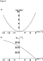
- ⁇ is to be determined such that equation (67) is satisfied. It should be noted here that there are generally two solutions for the axis cross angle ⁇ to a desired tooth thickness, which both lead to the desired result (see FIG. 5a ).
- FIG. 5b shows the necessary changes to the Achsnchwinkels and the axial distance compared to the prior art.
- the maximum possible tooth thickness for a given center distance is achieved at this axis cross angle.
- a change in the Achsnchwinkels leads to a reduction of the tooth thickness or an increase in the base gap angle, as in FIG. 5a to see.
- dressable grinding worms are used for processing, then this problem can occur if the worm has two flanks together with the worm head (Head area of the screw flights above the involute area) is dressed with a dresser in the same dressing stroke.
- the dresser is a dressing wheel, it can be equipped, for example, with a head dressing roller. Two possible variants of such dressing wheels are in FIG. 8 shown.
- Such a dresser can also be designed as a multi-ribbed dresser with a plurality of dressing disks, which dress more than one left and / or more than one right flank and one or more screw heads in the same dressing stroke.
- the dresser can also be designed as a dressing gear, which is suitable for dressing the screw heads in the same dressing stroke, as these are known from the prior art.
- the tooth thickness of the screw and the tip circle radius of the screw can no longer be specified independently during dressing. For a given tip radius of the screw, this thus has a non-influenceable tooth thickness. If this worm is ground with the axial cross-over angle according to the prior art with an axial distance which leads to the desired root radius on the workpiece, a tooth thickness which can not be influenced results on the workpiece. With the method presented here, foot radius and tooth thickness on the workpiece can now be specified independently of each other also in this case. This problem can occur, for example, if there were manufacturing deviations on the dresser, if the harvester is to be used for different teeth and / or if it is intended to switch between machining with and without a tooth root.
- the method can also be used to precisely adjust the head play of the tool.
- a root radius increased by the head play is used.
- the headgear of the tool is the distance that the head of the tool has from the foot of the workpiece during machining.
- the head clearance is set at least so large that, taking into account the manufacturing deviations of the workpiece and the tool and the correction movements during processing, in particular a correction of the axial distance to no processing of the tooth root.
- the Abtrag A a , A l and A r can also be specified independently and thus solves the described technological problems. So it may be advantageous, for example, when Wälzschleifen to select the same time in the tooth root and on the flanks for a stroke or even to choose the removal in the tooth root smaller than that on the flanks. This can be advantageous in particular during the last finishing stroke, since grinding of the tooth root can lead to deviations on the flanks.
- the tool foot circle radius is determined by the outside diameter of the dresser so that this diameter is to be considered in place of the outside diameter of the head dresser.
- d and ⁇ influence the assignment of rolling angles on the tool to rolling angles on the workpiece.
- This assignment is of particular importance if a modified profile on the workpiece is to be generated by a tool with a modified profile.
- profile modifications are, for example, profile angle modifications, profile crowns or head and foot returns.
- the assignment of rolling angles on the tool to rolling angles on the workpiece has no influence on the modification produced, the assignment influences the position of the other profile modifications.
- the position of the bend of a head withdrawal is influenced by the assignment. According to the prior art, so far only the influence of the axial distance d could be used to influence the position of the profile modification on the workpiece.
- FIG. 6a shows the displacement of the profile modification on the workpiece, measured as a shift in the rolling angle, as a function of ⁇ , wherein the tooth thickness was kept constant, that is, the center distance d runs as a function of ⁇ as in FIG. 5b shown.
- the tooth thickness was kept constant, that is, the center distance d runs as a function of ⁇ as in FIG. 5b shown.
- the possibility of independent adjustment of the displacement of the profile modification and the tooth thickness is of particular importance, for example, in hobbing and skiving and in hobbing with non-dressable tools. So now tools can be used, which would place the profile modification for the desired tooth thickness wrong. This may be the case, for example, if the tools were designed and / or manufactured incorrectly or if they were designed for other, in particular similar workpieces.
- a second application is generating grinding in conjunction with a double-sided dressing of the grinding worm.
- modified dressers are used which produce the required modification on the surface of the worm.
- the tooth thickness of the screw is set via the center distance between the screw and the dresser. However, this axial distance also determines the position of the profile modification on the surface of the screw at the same time. If now the worm is trued with the tooth thickness required according to the prior art, the result is a fixed position of the profile modification on the worm, which leads to a fixed position of the profile modification on the workpiece during generating grinding according to the prior art.
- the method described here now also makes it possible to influence the position of the profile modification on the workpiece in this application and thus to set and / or correct it, irrespective of the desired tooth thickness.
- the second essential aspect of the invention provides to change the Achsnchwinkel during a machining stroke depending on the axial feed z V 2 of the workpiece according to a continuous function ⁇ ( z V 2 ).
- This makes it possible to specify the tooth thickness and at least one of the sizes root circle radius on the workpiece, head circle radius on the workpiece, position of the profile modification on the left flank, position of the profile modification on the right flank depending on the workpiece width position.
- the cases in which a cylindrical workpiece and / or a cylindrical tool are used, arise as special cases by using the corresponding relations and viewing the cylinder jacket surfaces instead of the conical surfaces.
- a change in tooth thickness across the width of the workpiece is referred to as a flank line modification.
- the touch point moves along the touch track given on the workpiece for given axial feed positions of the tool z V 1 and the workpiece z V 2 neglecting the axial feed by Equation (48).
- This equation shows that the touch track in w F 2 and z F 2 is given by a straight line. Since the coefficient C Fw 2 depends only on the basic sizes of the workpiece, the direction of the straight line remains unchanged in the case of a change in the axial distance d and / or the axis cross angle ⁇ .
- a change in the machining kinematics in particular the changing of ⁇ and / or d and / or breaking of the rolling coupling by a change in the rotational angle of the tool and / or the workpiece and / or the axial feed positions of the tool z V 1 and / or the workpiece z V 2 lead to a modification f KFt ( w F , z F ) on the workpiece, which assumes a constant value along the current touch track and can be mathematically described as follows.
- the functions F KFt can be any continuous functions.
- ⁇ KF results directly from equation (48) from the direction of the touch track.
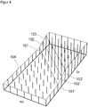
- FIG. 13 shows a modification according to equation (69) using the example of a naturally entangled flank line crown.
- the straight line 20 corresponds to the course of the touch track at a time of processing.
- the modification has a constant value along 20.
- F Klt and F Krt for left and right flank are taken from given functions taking into account an additional condition in ⁇ and / or d and / or z V 2 (eg head / root radius, position of profile modification, tool head play, tool foot play ) lets calculate the required change in the machining kinematics.
- the non-corrected machining kinematics here means the kinematics known from the prior art for machining unmodified workpieces. However, this non-corrected kinematics does not yet include the differential rotation required for helical gears, as well as the differential rotation required in diagonal machining. These differential rotations are also known in the prior art and are necessary in the conventional machining so that the constraint condition (R4) is satisfied at all times. If the axis cross-over angle is changed during machining, the differential rotation together with the required rotational angle corrections for the flank line modifications must be determined, which is shown below.
- X F The location of the touch track can be described by X F from equation (69).
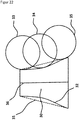
- FIG. 22 schematically shows a conical workpiece 30.
- the straight line 31 marks the course ofdon Vietnameseradius (course of the tooth base) in a conical workpiece according to the prior art.
- the straight line is tilted with respect to the axis of rotation around the foot cone angle.
- Such a course of the root radius results in a non-modified Machining kinematics.
- the Johannreisradius can now be freely specified for each width position of the conical workpiece.
- Figure 32 shows such a free course of the root radius over the width of the workpiece. If this course rotates about the axis of rotation 36 of the workpiece, then the resulting rotational body describes the course of the root circle three-dimensionally.
- the axial distance d depends on the Axialvorschubposition z V 2 , taking into account the Achsnchwinkels ⁇ be adjusted so that the cone sheath, which covers the tip circle of the tool, at any time tangentially rests against the body of revolution. This results directly in the sought additional condition for d and / or ⁇ .
- FIG. 22 schematically shows in section the tangentially applied to the rotational body enveloping cone shells 33, 34 and 35 of the tool for three different axial feed positions z V 2 simplified as circles shown.
- the course of the primanikradius can be freely selected within wide limits.
- the free courses can also be selected in a straight line, in particular.
- the straight line is tilted with respect to the axis of rotation at an angle deviating from the cone angle.
- a free course of the tip circle radius can also be produced here.
- the calculation proceeds analogously, only the foot taper of the tool must touch the free course of the tip circle tangentially for each axial feed position z V 2 .
- the rotational body resulting from the rotation of the course of the tip circle about the axis of rotation 36 of the workpiece is referred to as the envelope of the workpiece.
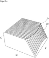
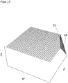
- the shift of the profile modification can take free forms within certain limits. Thus, for example, a shift can be selected in which the length of the tip retraction from one end of the toothing to the other end continuously increases or decreases. Thus, for example, a triangular end return 24 can be generated, as in FIG. 15 will be shown. Since the shape of the profile modification (eg crowning, head / foot return) is determined solely by the tool, this method can be used to move any profile modifications. It should be noted that the shift of the profile modification always has an effect along the current touch track.
- the shape of the profile modification eg crowning, head / foot return
- Equation (48) The different position of the touch track on the left and right flank for given axial feed positions z V 1 and z V 2 can be influenced inter alia by the profile angle of the tool used but also by the set Achsnchwinkel.
- FIG. 16 shows for three different profile angles ⁇ of the tool used, as the traces of contact on the left and right flanks run for fixed axial feed positions. In the example shown causes a larger profile angle of the tool displacement of the touch track on the right flank in the width direction upwards, on the left flank in the width direction downwards.
- the axis cross angle ⁇ set for machining likewise influences the position of the contact lines on the left and right flanks with respect to one another.
- FIG. 17 shows for three different Achsnchwinkel ⁇ , as the traces of contact on the left and right flank for recorded Axialvorschubpositionen run. In the example shown causes a larger Achsnchwinkel a shift of Berchanrockspur on the right flank in the width direction up, on the left flank in the width direction down. This effect is generally always to be considered, but is automatically taken into account by equation (48).
- the axis cross angle to be set for a given center distance when machining a given workpiece is given by the tooth thickness of the tool and can be calculated using Equation (67), where there are generally two solutions for ⁇ . Conversely, the tooth thickness of the tool can also be calculated for a given axis cross angle.
- This relative position of the touch tracks influences how a displacement of the profile modification on one flank realized with the method described here has an effect on the other flank. If, for example, a displacement of the profile modification is to be realized on both flanks and the curves are similar in the width direction, but offset in the width direction against each other, the shift of the contact lines can be adjusted so that a shift of the profile modification on the flank automatically, at least approximately, to correct shift of the profile modification on the other flank leads.
- the position of the touch tracks to each other and the course to be achieved the displacement of the profile modification on a flank for example by means of a compensation calculation optimized so that there is an optimal course of the displacement of the profile modification on both flanks.
- a compensation calculation optimized so that there is an optimal course of the displacement of the profile modification on both flanks.
- the distance of the desired displacement of the profile modification to the shift achieved over the tooth width on both flanks can be used. If the desired displacement of the profile modification over the gear width and / or on the left and right are tolerated differently, a distance function can additionally be selected which weights the different width positions and / or flanks differently.
- the maximum possible amount by which the profile modification can be shifted to the tooth root is only limited by how much head play of the tool is available during machining.
- a shift in the profile modification towards the tooth root is achieved by reducing the axial distance and thus leads to a reduction in head play of the tool.
- a tool with a head circle radius adapted correspondingly over the tool width can be used and the method can be carried out as a diagonal rolling method.
- the tip circle of the tool and the axial feed of the tool z V 1 ( z V 2 ) are adjusted so that at each workpiece width position a tip radius of the tool acts, which prevents both unwanted editing of the tooth root of the workpiece or edited the tooth root with the desired anatomy numero Vietnamese as well as a processing of the sansform Vietnamesees of the workpiece ensures. It should be noted that this adjustment of the tool must be made only on the top circle. The shape of the flanks remains unchanged.
- the tip circle is determined at each latitudinal position of the workpiece which engages so that the rotation body resulting from the course of the tip circle tangent to the rotational body of the course of the root radius of the workpiece at any time.
- This calculation shows that there is not a solution for every axial feed of the tool z V 1 ( z V 2 ).
- the remedy here is an increase in the diagonal ratio, which leads to a longer shiftweg and thus to a longer used area on the tool.
- the diagonal ratio is to be increased in amount until a solution can be found.
- a non-constant diagonal ratio can be assumed here and this can be determined for each axial feed position of the workpiece z V 2 so that a solution can be found.
- This calculation method provides the shortest possible shiftweg and thus also the shortest possible used area on the Tool.
- a further preferred calculation method takes into account not only the desired course of the prima Vietnamese radicals on the workpiece, but also the allowable tolerance of the course of predominantly Vietnamese radicals and leads to further shortened shift ways.
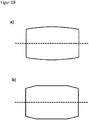
- FIG. 18a shows, for example, the envelope body a cylindrical tool with an arcuately over the tool width changing tip circle radius.
- a cylindrical tool with an arcuately over the tool width changing tip circle radius.
- Such a tool can be used, with a constant diagonal ratio with the method described herein, an arcuate over the workpiece width displacement of the profile displacement, as this example in FIG. 14 is shown to produce.
- the axial distance must be reduced in order to shift the profile modification in the direction of the tooth root.
- the areas of the tool then have to come into contact with the reduced head circle radii so as not to violate the root radius of the workpiece.
- the center of the toothing is made, the center distance must be increased in order to move the profile modification towards the tooth head.
- the area of the tool with large tip radius must come into contact.
- FIG. 18b shows the enveloping body a cylindrical tool with at the two ends linearly reduced over the width of the head circle radius, which can be used, for example, with constant diagonal ratio a modification as in FIG. 15 shown to be finished.
- FIG. 15 A modification like in FIG. 15
- a tool like in FIG. 18a be made.
- the axial feed z V 1 ( z V 2 ) of the tool is to be selected as a function of z V 2 , that at any time a region of the tool comes into contact, whose tip radius just corresponds to the required tip circle.
- the diagonal ratio would initially be continuously smaller, while the unmodified area is manufactured to be zero and then continuously increase again.
- Another variant is a tool whose head circle monotonously increases from one end to the other end, for example linearly. With such a tool would be for the two exemplified modifications FIG. 14 and 15 a direction reversal of the diagonal ratio needed.
- FIG. 18 shows only cylindrical tools by way of example. If conical tools are used, the adaptation of the tip radii with respect to the conical surface instead of the cylinder surface is to be carried out.
- Periodically recurring curves of the tip circle radii can also be provided on the tool.
- a tool 40 is exemplary in FIG FIG. 20 shown. This has three periodically recurring areas 41, 42, 43. Each of these areas has a course of the tip circle radius similar to that in FIG. 18a shown tool. A division into such areas is useful, for example, when roughing and finishing operations are to be carried out on different areas.
- the width of the various areas on the tool can be freely selected within wide limits and is preferably chosen so that the tool is optimally utilized and / or the wear is minimized as possible. For example, in generating grinding, it is advantageous to apply as many identical areas on the screw as possible, and to use each of these areas first for finishing and when it is worn, even further for roughing.
- the different areas can be used, for example, for roughing / finishing or polishing, and different abrasive materials or specifications of the abrasives can be used on these areas.
- Another application envisages that areas, if they have not yet worn out and are thus able to produce a good profile, be used for finishing, if these are then worn out and used for roughing.
- a division into up to 20 or more areas is conceivable.
- the process is used for generating grinding with dressable screws, various possibilities are available for dressing the screw heads.
- the tooth root is to be co-machined with the screw, then it is generally desired to purposefully round the screw heads so as to produce the desired foot geometry. This requires dressing the Schneckenköpf with a head dressing roll.
- a head dressing roller 50 is in FIG. 8 as part of a combination dresser and known from the prior art. With such a head dressing roller, each flight is trained individually. For this purpose, the screw is guided in the axial direction of the head dressing roller and coupled according to their pitch height rotated about its axis of rotation. In the case of conical screws, the axial distance between the worm and the head dressing roll is additionally adjusted in accordance with the taper of the worm.
- a worm is to be dressed with a predetermined course of the tip circle radius, then the center distance is required during dressing between Kopfabrichtrolle and screw, depending on the axial position of the screw to adapt so that the desired course of the tip radius over the width of the screw is formed.
- snails can only give me one area ( FIG. 18 ), Snails with several different areas or even snails with periodically recurring areas ( FIG. 20 ) are trained. Since the course of the tip circle radius is realized purely via the dressing kinematics, such a head dressing roll can be used very universally and for any course of the tip circle radius.
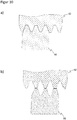
- a multi-ribbed head dressing roller 51 can be used for periodically recurring regions ( FIG. 9a ).
- the tooth heads are trained several, preferably all courses of a screw in a Abrichtbub.
- the kinematics during dressing is identical to that of a conventional head dressing roller 50 when using such a multi-ribbed head dressing roller. Only a longer inlet path and / or a longer outlet path is to be chosen so that all screw flights are trued so that the total required shiftweg increases during dressing.
- a worm with a predetermined course of the tip circle radius is to be dressed with such a multi-ribbed head dressing roll
- the changes in the axial distance between worm and head dressing roll affect all worm threads which are in contact at the same time, albeit at different width positions. If the period of the recurring areas in the worm's width direction has just been selected to correspond to the distance between two adjacent contact points between the head-dressing roller and the worm in the worm-width direction, then the periodic course of the tip-circle radius will be the same across all the widths of the worm desired periodic course of the tip circle radius on the enveloping body is achieved.
- the dressing strokes are repeated, both for dressing the flanks and for dressing the screw heads, wherein the dresser is brought into engagement with the screw by one screw flight.
- the number of flights of the screw need not be an integer multiple of the tooth of the ribs on the dresser be. If this is not the case, at least one check passage is trained during two dressing strokes.
- flanks of the screw except for the required profile modifications, are not further modified and in particular are not modified across the width, they can be dressed with all dressing methods known from the prior art. This includes in particular profile roller sets, double cone pulleys, multi-ribbed dressers and dressing gears.
- the required profile modifications can be realized by the used dressing tool on the worm.
- the most economical method here is the use of multi-ribbed dressers. These simultaneously align at least two left and / or at least two right flanks, but preferably the left and right flanks of all flights.
- Such dresser can be designed as a solid profile rollers and thus used for simultaneous dressing of the flanks of the screw and the screw heads. In this case, however, it is no longer possible to specify a free course of the tip radius on the screw, since a change in the axial distance between the screw and dresser would also affect the shape of the flanks of the screw.
- This invention therefore proposes a dresser 55 with a head dressing function, which is designed so that it can be used to machine the heads of the screw threads with the outside diameter.
- the dresser can be executed both Purrippig, as in FIG. 10 shown by way of example on a dreirippigen dresser, but it can also be designed einrippig.
- head dressing function As in FIG. 10a shown engaged with the worm and it trained in one or more strokes the flank, as is known in the art.
- the ribs of the dresser are brought into contact with the heads of the flights at their outer diameter.
- the dressing kinematics corresponds to the dressing of the flanks.
- the worm is moved axially and rotated according to its pitch height about its axis of rotation, in the case of conical worms, the center distance between dresser and worm is also changed according to the cone angle.
- the dresser may have corresponding profiles on the outer diameter.
- FIG. 12a shows a worm gear 60 with a flattened towards the flanks worm head in engagement with a dresser 62 with Kopfabrichtfunktion with a rounded at the outer diameter provided with an abrasive substance profile 65.
- Such dresser with Kopfabrichtfunktion is particularly suitable when the tooth root of the Workpiece is to be ground.
- the rounding on the dresser can be selected so that the desired shape, in particular rounding is formed at the tooth root of the workpiece. A variant of this would be fully rounded snail heads.
- 64 and 64 ' are the abrasive coated profiles for dressing the left and right flanks of the screw, respectively.
- FIG. 12b shows a worm gear 61 with not rounded head in engagement with a dresser 63 with Kopfabrichtfunktion with a, on the outside diameter flat provided with an abrasive substance profile 67.
- a dresser is particularly useful when the tooth root of the workpiece is not to be ground.
- a dresser on the outer diameter dresser is sufficient here in comparison to the variant FIG. 12a , 66 and 66 'are the abrasive coated profiles for dressing the left and right flanks of the screw, respectively.
- a dresser with Kopfabrichtfunktion designed Offset it may, as the Morippigen Kopfabrichtrollen 51 and 53 are used to achieve over the worm width a freely predetermined periodically recurring course of the tip radii.
- the advantage over the multi-ribbed head dressing rollers is that the dresser with head dressing function can be used both for dressing the flanks and for dressing the heads of the screw threads. Thus, only one tool and only one dresser spindle in the gear cutting machine are needed. If the period of the recurring widthwise portions of the worm corresponds to the distance between two adjacent contact points between the multi-ribbed dresser with head dressing function and screw in the worm width direction, a dresser 55 having a head dressing function that simultaneously machines adjacent gaps may be used.
- a multi-ribbed dresser with head-dressing function whose pitch of the individual ribs is straight can be used analogously to the head-dressing roller 53 is chosen so that only every V te worm gear is in contact.
- the invention further provides a multi-ribbed dresser with Kopfabrichtfunktion, in which not all ribs on the outer diameter with a profile which is suitable for dressing a screw head, are madestatte. Such withdrawn ribs then have an outer diameter which is smaller than that of the ribs provided with a profile on the outer diameter, so that these ribs have no contact with the screw when dressing the screw heads. Preferably, only each V te rib is provided with a profile on the outer diameter. Such a dresser then allows true the flanks of the screw in fewer strokes than would be necessary with a dresser having only each V th rib.
- a 6-screw worm is to be trued and the periodically recurring course of the tip radius on the worm requires that only every second screw head can be trued simultaneously with a multi-ribbed dresser with head dressing function
- a 6-ribbed dresser with head dressing function can be used the only every second rib has a profile for dressing the screw heads on the outer diameter.
- the flanks of all screw flights can be dressed in a dressing stroke, all screw heads in two dressing strokes.
- the outer diameter of the recessed ribs must be so large that when dressing the flanks of the screw, the screw is profiled by these ribs deep enough so that the worm does not overwhelm the head of the workpiece unintentionally.
- the outer diameter must be chosen so small that, when the worm heads are being dressed by the changing center distance between the worm and the dresser, unwanted contact of a recessed rib with a worm head does not occur.
- either the flanks or the screw heads can be dressed in one stroke.
- a small center distance between the dresser and the worm is selected when dressing the worm heads in comparison to dressing the flanks.
- the head dressing roller 54 comes into contact with the screw heads.
- a different axis intersection angle between the dressing rotation axis and the screw rotation axis is set when dressing the flanks in comparison to dressing the heads of the screw flights.
- the axis crossing angle between the dressing rotation axis and the screw rotation axis is selected to be equal to the helix angle of the screw.
- the double-cone disc is designed accordingly for this Achsnchwinkel. However, it is also possible to dissect a worm with different axis of the helix angle of a worm, wherein this axis cross angle can be varied in both directions. If a double-cone pulley is designed for such an alternative axis cross-angle, the double-cone disc will be narrower. This effect is exploited in the combination dresser proposed here and the proposed method. For this purpose, the double-cone pulley is designed for a different axis angle from the helix angle of the screw and used for dressing the flanks under this axis cross-angle ( FIG. 11a ), wherein the dressing can be done both one-flanked as well as double-sided.
- the heads of the screw flights ( FIG. 11b ) sets an Achsnchwinkel which is closer to the helix angle of the screw and is preferably equal to the helix angle of the screw.
- the alternative Achsnchwinkel is to be chosen so that the double-cone disc has sufficient clearance to the flanks even when necessary for dressing the heads of the screw threads reduction of the axial distance between the screw and combi dressers.
- the alternative Achsnchwinkel deviates between 0.1 ° and 10 ° from the helix angle of the screw.
- screws can also be dressed with dressing tiles.
- dressing tiles are fixedly secured in the hobbing machine and the screw, while rotating at a sufficiently high speed to achieve the necessary cutting speed, is axially guided past the dressing tile.
- the Dressing tile for example, as in FIG. 19 shown to be executed with a flat abrasive surface 70.
- Another embodiment provides for the use of a needle-shaped tile, which is particularly preferred when the course of the head radius has small radii of curvature.
- a preferred embodiment in particular for mass production, provides a special dressing tile 44 whose shape corresponds to the abrasive surface 47 exactly the course of the tip circle radius.
- a dressing tile 44 is in FIG. 20 along with the envelope 40 of the screw for which the dressing tile was designed.
- the worm must be driven so only once rotating at the correct distance to the dressing tile.
- the desired course is formed, without the worm having to be guided past the dressing tile, whereby the dressing time is significantly shortened.
- the length of the dressing tile preferably corresponds to the length of the screw.
- Another embodiment provides a shorter and thus less expensive dressing tile 45, which is suitable for the simultaneous dressing of a portion of the screws.
- Its shape of the abrasive surface 46 corresponds exactly to a part of the course of the tip circle radius of the screw. If the worm has a periodically recurring course of the tip circle radius, then the worm can be trued over the entire length in several processing steps. Depending on the embodiment, only one periodic area or several periodic areas can be dressed per processing step.
- the width of this special dressing tile, which is in FIG. 20 extends into the paper plane, can be chosen freely. The wider it is made, the more latitude it can be used and the more dressing cycles it can be used until it is worn out.
- a free flank line modification is to be achieved and at least two additional conditions are to be fulfilled at the same time, then this is generally not possible with the method presented here.
- Hang the permitted tolerances of Axialvorschubposition z V 2 from that additional conditions may be weighted differently depending on the optional 2 Axialvorschubposition for V.
- the additional conditions may be: course of the foot or head circle of the workpiece depending on the workpiece width position or displacement of the profile modification on the left or right flank of the workpiece depending on the workpiece width position.
- the deviation from the desired geometry can be determined, this deviation is preferably determined as the maximum deviation of the desired geometry of the generated geometry, more preferably as the sum of flank line angle deviation f H ⁇ and profile angle deviation f H ⁇ .
- the deviation of the desired geometry as a function of ⁇ 2 and ⁇ 2 is an example in FIG FIG. 23 shown.
- the deviation becomes minimal at point 71.
- the minimum value is a value for ⁇ 2 which deviates from the root angle ⁇ 2 of the workpiece. If now the toothing with the values for ⁇ 2 and ⁇ 2 for the deviation is minimal, according to the prior art, the workpiece would be manufactured with a wrong root angle ⁇ 2 .
- the deviations of ⁇ 2 from the desired root angle may range from a few hundredths of a degree up to 5 ° or more, depending on how far the tool deviates from a combing tool. In particular, larger deviations from ⁇ 2 lead to deviations of the desired din Vietnamese tolerances.
- the invention now provides for the machining process to be designed as if the workpiece were to be machined with the values determined for ⁇ 2 and ⁇ 2 . This process would deliver a workpiece with minimal deviation to the desired geometry.
- This method offers over a variant in which only ⁇ 2 is used for the optimization and ⁇ 2 is chosen equal to the target cone angle of the workpiece, in particular great advantages if the tool and / or workpiece have asymmetric profiles and / or if the workpiece is conical.
- the Achsnchwinkel ⁇ continuously change during processing to apply the procedure for generating free gradients of mon Vietnameseradius, so can, especially in large gears, the Achsnchwinkel only at several specific Axialvorschubpositionen of the workpiece are adjusted and kept constant between these axial feed positions of the workpiece. It is also conceivable, the axial feed of the workpiece during the change of Achsnchwinkels to keep constant or even interrupt the processing for a short time or to bring the tool out of service for a short time. The method thus executed would then lead to larger, in particular erratic deviations on the workpiece produced.
- the invention further provides software which determines from a selection of tools whose geometry data are stored, for example, in a database, the tool or tools which are or are best suited for the application of the method just described, in particular the produces or generates the smallest deviation from the desired geometry.
- FIG. 24 shows this influence using the example of a tooth gap that is symmetrical in the face section.
- the evolvent 80 produced is identical at different profile angles, but the foot geometry 81 and 82 are different.
- 81 corresponds to a larger profile angle compared to 82.
- the actually generated foot geometry depends not only on the kinematics but also on the shape of the tooth head of the tool, but the qualitative influence of the profile angle on the foot geometry described here is independent of the actual shape of the tooth head.
- the actual generated foot geometry both in the case of a constant and a continuously changed axis intersection angle, can be calculated with a removal simulation taking into account the kinematics and the tooth shape of the tool.
- a higher material removal in the foot leads to a weaker tooth root and can therefore more easily lead to a fracture of the tooth root.
- a too small request may lead to a collision with the head of the counter-wheel in the installed state.
- the influence of the profile angle on the foot geometry can also be used selectively, in particular in order to influence the change of the foot geometry over the workpiece width in the case of conical workpieces.
- conical toothing is produced using one of the machining methods considered here according to the prior art, the result is a foot geometry which changes continuously over the width of the workpiece and which follows from the continuously changing profile displacement factor.
- This changing foot geometry is determined inter alia by the shape of the tooth head of the tool and by the cone angle.
- the cone angle corresponds to theintuitkegelwinkel.
- a rectilinear course of the root radius is predetermined, which is offset by a distance of ⁇ 2 from the axis of rotation of the Workpiece tilted straight is given.
- the axial distance must be adjusted with respect to an uncorrected processing and according to FIG. 5b the Achsnchwinkel ⁇ be adapted, which according to FIG. 6b leads to a change in the profile angle of the theoretical rack and as in FIG. 24 shown leads to an altered removal in the tooth root.
- Whether or not the wear in the foot increases or decreases from toe to heel over the prior art method can be controlled by choosing an alternative cone angle ⁇ 2 which is less than or greater than ⁇ 2 and above, whether to compensate for changed axis distance of the axis cross angle via the left ( ⁇ ⁇ ⁇ 0) or the right ( ⁇ ⁇ > 0) part of the function in FIG. 5b is compensated.
- the alternative cone angle ⁇ 2 is chosen so that the center distance must be increased from toe to heel and the increase in the axial distance on the right part of the function FIG. 5b is compensated, this leads to an enlargement of the Achsnchwinkels from toe heel, which in turn according to the function in FIG.
- FIG. 25 illustrates the dependence of the profile angle of the change in the center distance for the two variants ⁇ ⁇ ⁇ 0 and ⁇ ⁇ > 0. It is found that the magnitude of the slope of the two functions for small changes ⁇ d is large, for large changes ⁇ d small , This can be used to influence not only the profile angle of the toe and heel but also the profile of the profile angle between them. If, for example, in the example considered, the center distance needs to be changed by 0.5mm and the range from 1.5mm to 2.0mm is used for this purpose, the result is FIG. 25 an approximately linear change in the profile angle across the width of the workpiece.
- the alternative cone angle ⁇ 2 and one or more of the following influencing variables can be determined, for example by means of a compensation calculation, such that the desired foot geometry is optimally approximated: 1) Shape of the tooth tip of the tool, 2) sign of ⁇ ⁇ , 3) range of the function FIG. 25 ,
- the alternative cone angle ⁇ 2 and one or more of the three influencing variables can also be determined in such a way that the application behavior, in particular the Tooth foot bearing capacity of the workpiece to be optimized.
- a removal simulation which determines the resulting over the width of the workpiece constantly changing foot geometry, are used, and to use the result in a program for determining in particular calculation and / or simulation of the use behavior, especially the Zahnfußtragjo.
- the invention thus also provides for the alternative cone angle ⁇ 2 and thus the profile angles ⁇ nF 2 on the left and right flanks to be determined such that the desired geometries can be achieved at the non-involute areas, in particular at the foot and the head.
- the additional conditions in ⁇ and / or d and / or z V 2 also include those which are additional conditions in the profile angles of the theoretical rack.
- these additional conditions which require a profile angle in a certain range, in order to generate certain geometries in the non-involute range, are also included.
- the diagonal ratio is generally limited to the bottom, ie it is a minimum Shiftweg required, the diagonal ratio, however, can be freely selected upwards. In all other embodiments, a processing in the diagonal rolling process is not necessary, but easily possible.
- the diagonal ratio can be both constant and non-constant in all cases.
- a special application of the combination with Diagonaldicalz Kunststoffmaschinen results when an at least by ⁇ and / or d and z V 2 dependent additional condition should be met, in particular a free course of the foot or tip circle radius is to be achieved on the workpiece and at the same time a targeted shift of the profile modification , In particular, a profile modification, which is not shifted over the width of the workpiece. If additional conditions are fulfilled via the method presented here, this automatically leads to a shift of the profile modification across the width of the workpiece on both flanks. However, this shift is generally not the desired one.
- a tool can be used on which the profile modification is just shifted over the tool length so that the correct displacement of the profile modification on the workpiece is formed taking into account the machining kinematics. If the machining process used is hobbing with dressable screw, then the screw must be dressed accordingly.
- the DE 10 2015 000 907 describes a method for dressing a worm with a dressing wheel, which allows to map a diameter on the dressing wheel to a diameter or Wälzweg on the worm and to freely choose this assignment over the worm width. Depending on the application, the dressing can be carried out in one or two layers.
- Whether the dressing can be performed with two flanks depends on whether, in the case of double-sided dressing of the screw, there is an assignment of diameters can be achieved on the dressing wheel to Wälzwinkeln on both flanks of the screw, which is the later Wälzschleifen on both flanks to a shift of the profile modification across the width of the workpiece within the desired tolerance.
- This method can also be realized with a tool with a predetermined course of the head or root radius, so that the foot or tip radius on the workpiece, both from the machining kinematics and the geometry of the tool is formed. This is particularly advantageous if an additional condition independent of the foot and head circle is used, since in this way, the foot or head circle, displacement of the profile modification and the additional condition can be fulfilled.
- the diagonal rolling method is also particularly advantageous if, for technological reasons, for example in order to avoid excessive wear of the tool, different areas of the tool are to be brought into engagement during a stroke.
- the method is applied in the variant in which the axis intersection angle is varied during a machining stroke, as can be influenced by the tooth thickness of the area in which the change of the axis intersection angle ⁇ ⁇ is.
- the latter variant may be advantageous because it does not affect a possibly existing backlash of the axis used for the realization of Achsnchwinkels or axes.
- a further aspect of preferred tools to be used with a defined cutting edge, in particular hob cutters and skiving hobs, is that due to the change in the swivel angle, a change in the clearance angle can occur, which can adversely affect the service life of the tool. It is therefore preferable to use tools whose relief grinding is designed so that at all to be set in the process Achsnchwinkeln, a sufficiently large clearance angle on the cutter tooth is present.
- the self-adjusting clearance angles can be determined, for example, within the framework of a production simulation and thus adapted accordingly.
- the clearance angle should preferably be greater than 0.5 °, more preferably greater than 2 °, for all axis cross angles to be set in the process.
- the flank line modifications may be freely selected on the left and right flanks and may in particular be flank line angle modifications, flank line bumps, flank line bolls and / or end reductions.
- flank line may occur. Such deviations are compensated in the gear cutting machine via a flank line correction.
- the flank line modifications considered here are to be understood as the sum of the desired flank line modifications and the possibly necessary flank line correction.
- flank line modification may be constant, in particular 0, on one or both flanks.
- a workpiece can also be manufactured without flank line modification while fulfilling the additional condition.
- a special application of the invention provides, preferably in a processing of the tooth root to specify the course of the tooth root as a tilted about the Schwarzkegelwinkel relative to the axis of rotation, so as to produce a toothing, the course of the dominant Vietnameseradius of the flank line modification remains unaffected.
- This also leads to the fact that the flank line modification essentially by a change in the Achsnchwinkels and not realized by a change in the center distance. This can be advantageous if the axis or the axes, which are used for adjusting the Achsnchwinkels can be set more accurately than the axis or the axes, which are used to adjust the center distance.
Landscapes
- Engineering & Computer Science (AREA)
- Human Computer Interaction (AREA)
- Manufacturing & Machinery (AREA)
- Physics & Mathematics (AREA)
- General Physics & Mathematics (AREA)
- Automation & Control Theory (AREA)
- Mechanical Engineering (AREA)
- Computing Systems (AREA)
- Theoretical Computer Science (AREA)
- Grinding-Machine Dressing And Accessory Apparatuses (AREA)
- Turning (AREA)
Applications Claiming Priority (1)
| Application Number | Priority Date | Filing Date | Title |
|---|---|---|---|
| DE102016005210.4A DE102016005210A1 (de) | 2016-04-28 | 2016-04-28 | Verfahren zur Verzahnbearbeitung eines Werkstückes |
Publications (3)
| Publication Number | Publication Date |
|---|---|
| EP3242176A2 true EP3242176A2 (fr) | 2017-11-08 |
| EP3242176A3 EP3242176A3 (fr) | 2017-12-06 |
| EP3242176B1 EP3242176B1 (fr) | 2021-06-02 |
Family
ID=58578866
Family Applications (1)
| Application Number | Title | Priority Date | Filing Date |
|---|---|---|---|
| EP17166831.2A Active EP3242176B1 (fr) | 2016-04-28 | 2017-04-18 | Procédé d'usinage des engrenages d'une pièce |
Country Status (2)
| Country | Link |
|---|---|
| EP (1) | EP3242176B1 (fr) |
| DE (1) | DE102016005210A1 (fr) |
Cited By (2)
| Publication number | Priority date | Publication date | Assignee | Title |
|---|---|---|---|---|
| EP3241640B1 (fr) | 2016-05-02 | 2018-11-28 | Kapp Werkzeugmaschinen GmbH | Procédé de finition à haute dureté de la denture d'une roue dentée ou d'un profil semblable à une roue dentée d'une pièce usinée |
| WO2022018223A1 (fr) * | 2020-07-23 | 2022-01-27 | Gleason-Pfauter Maschinenfabrik Gmbh | Procédé pour usiner et produire une denture sur une pièce |
Families Citing this family (2)
| Publication number | Priority date | Publication date | Assignee | Title |
|---|---|---|---|---|
| CN111774668A (zh) * | 2020-07-14 | 2020-10-16 | 金华新天齿轮有限公司 | 短齿面弧齿锥齿轮接触区优化方法 |
| CN112798270B (zh) | 2020-12-21 | 2023-05-23 | 北京工业大学 | 一种渐开螺旋圆柱齿轮的法向啮合齿形测量方法 |
Citations (3)
| Publication number | Priority date | Publication date | Assignee | Title |
|---|---|---|---|---|
| DE10208531A1 (de) | 2002-02-27 | 2003-09-04 | Reishauer Ag | Verfahren zur Modifikation von Flankenlinien und/oder zur Korrektur von Flankenlinienabweichungen eines Zahnrads |
| DE102015000907A1 (de) | 2015-01-23 | 2016-07-28 | Liebherr-Verzahntechnik Gmbh | Verfahren zur Verzahnbearbeitung eines Werkstückes durch ein Diagonalwälzverfahren |
| DE102015008956A1 (de) | 2015-07-10 | 2017-01-12 | Liebherr-Verzahntechnik Gmbh | Verfahren zur Herstellung eines verzahnten Werkstückes mit modifizierter Oberflächengeometrie |
Family Cites Families (6)
| Publication number | Priority date | Publication date | Assignee | Title |
|---|---|---|---|---|
| JP5285526B2 (ja) * | 2009-07-27 | 2013-09-11 | 三菱重工業株式会社 | 内歯車加工方法およびそれに使用する工具のドレス方法 |
| EP2596893A1 (fr) * | 2011-11-25 | 2013-05-29 | Klingelnberg AG | Procédé d'écroutage partiel doté de deux angles de croisement d'axe et utilisation d'un outil d'écroutage correspondant pour l'écroutage partiel |
| DE102012015846A1 (de) * | 2012-04-17 | 2013-10-17 | Liebherr-Verzahntechnik Gmbh | Verfahren und Vorrichtung zum Hartfeinbearbeiten von modifizierten Verzahnungen |
| DE102012108717A1 (de) * | 2012-09-17 | 2014-03-20 | Präwema Antriebstechnik GmbH | Verfahren zum Modifizieren der Flanken eines Zahns eines Zahnrads mit Hilfe eines Werkzeugs |
| DE102014007646A1 (de) * | 2014-05-23 | 2015-11-26 | Liebherr-Verzahntechnik Gmbh | Verfahren zur Lagebestimmung der Evolventen bei Verzahnungen |
| DE102014108438A1 (de) * | 2014-06-16 | 2015-12-17 | Profilator Gmbh & Co. Kg | Verfahren zum Einarbeiten von Hinterlegungen in Zahnflanken der Zähne von Zahnrädern |
-
2016
- 2016-04-28 DE DE102016005210.4A patent/DE102016005210A1/de not_active Withdrawn
-
2017
- 2017-04-18 EP EP17166831.2A patent/EP3242176B1/fr active Active
Patent Citations (3)
| Publication number | Priority date | Publication date | Assignee | Title |
|---|---|---|---|---|
| DE10208531A1 (de) | 2002-02-27 | 2003-09-04 | Reishauer Ag | Verfahren zur Modifikation von Flankenlinien und/oder zur Korrektur von Flankenlinienabweichungen eines Zahnrads |
| DE102015000907A1 (de) | 2015-01-23 | 2016-07-28 | Liebherr-Verzahntechnik Gmbh | Verfahren zur Verzahnbearbeitung eines Werkstückes durch ein Diagonalwälzverfahren |
| DE102015008956A1 (de) | 2015-07-10 | 2017-01-12 | Liebherr-Verzahntechnik Gmbh | Verfahren zur Herstellung eines verzahnten Werkstückes mit modifizierter Oberflächengeometrie |
Non-Patent Citations (1)
| Title |
|---|
| NIEMANN, G; WINTER, H: "Maschinenelemente", vol. 3, 1983, SPRINGER VERLAG |
Cited By (3)
| Publication number | Priority date | Publication date | Assignee | Title |
|---|---|---|---|---|
| EP3241640B1 (fr) | 2016-05-02 | 2018-11-28 | Kapp Werkzeugmaschinen GmbH | Procédé de finition à haute dureté de la denture d'une roue dentée ou d'un profil semblable à une roue dentée d'une pièce usinée |
| WO2022018223A1 (fr) * | 2020-07-23 | 2022-01-27 | Gleason-Pfauter Maschinenfabrik Gmbh | Procédé pour usiner et produire une denture sur une pièce |
| CN115835928A (zh) * | 2020-07-23 | 2023-03-21 | 格里森-普法特机械制造有限公司 | 用于机加工和生产工件上的齿部的方法 |
Also Published As
| Publication number | Publication date |
|---|---|
| EP3242176B1 (fr) | 2021-06-02 |
| DE102016005210A1 (de) | 2017-11-02 |
| EP3242176A3 (fr) | 2017-12-06 |
Similar Documents
| Publication | Publication Date | Title |
|---|---|---|
| EP3242175B1 (fr) | Procédé d'usinage des engrenages d'une pièce | |
| EP3050660B1 (fr) | Procédé d'usinage de dentures d'une pièce à usiner selon un procédé de laminage diagonal | |
| DE102010023830B4 (de) | Verfahren und Werkzeugmaschine zum Bearbeiten einer Verzahnung, Computerprogrammprodukt und Verzahnung | |
| EP3139226B1 (fr) | Procede d'ajustement d'un outil | |
| EP3139229B1 (fr) | Procede d'ajustement d'un outil | |
| EP3050659B1 (fr) | Procédé et dispositif d'usinage de dentures d'une pièce à usiner selon un procédé de laminage diagonal | |
| EP3139227B1 (fr) | Procede de fabrication d'une piece usinee presentant une geometrie de denture souhaitee | |
| EP3053687B1 (fr) | Procédé et dispositif d'usinage de dentures d'une pièce à usiner selon un procédé de laminage diagonal | |
| EP3050658A1 (fr) | Procédé de fabrication d'une pièce usinée présentant une géométrie de denture corrigée et/ou d'une structure de surface modifiée | |
| EP3147059B1 (fr) | Procede de fabrication d'une piece usinee presentant une geometrie de denture modifiee | |
| EP3139231B1 (fr) | Procede de fabrication d'une piece dentee comprenant une geometrie de surface modifiee | |
| EP3118699B1 (fr) | Procede de fabrication d'une piece dentee comprenant une geometrie de surface modifiee | |
| EP3242176B1 (fr) | Procédé d'usinage des engrenages d'une pièce | |
| EP3281733B1 (fr) | Procédé d'ajustement d'une meule à vis | |
| DE102016008991A1 (de) | Verfahren zum Abrichten einer Schleifschnecke und Abrichtzahnrad | |
| EP3139230A2 (fr) | Procede de fabrication d'une piece dentee comprenant une geometrie de surface modifiee | |
| EP2848348A2 (fr) | Procédé de fabrication d'un outil de dressage, outil de dressage et procédé de dressage d'une meule à vis | |
| EP3139228B2 (fr) | Procede de fabrication d'une ou plusieurs pieces a usiner | |
| DE102024100637A1 (de) | Verfahren zur Herstellung eines verzahnten Werkstücks |
Legal Events
| Date | Code | Title | Description |
|---|---|---|---|
| PUAI | Public reference made under article 153(3) epc to a published international application that has entered the european phase |
Free format text: ORIGINAL CODE: 0009012 |
|
| STAA | Information on the status of an ep patent application or granted ep patent |
Free format text: STATUS: THE APPLICATION HAS BEEN PUBLISHED |
|
| PUAL | Search report despatched |
Free format text: ORIGINAL CODE: 0009013 |
|
| AK | Designated contracting states |
Kind code of ref document: A2 Designated state(s): AL AT BE BG CH CY CZ DE DK EE ES FI FR GB GR HR HU IE IS IT LI LT LU LV MC MK MT NL NO PL PT RO RS SE SI SK SM TR |
|
| AX | Request for extension of the european patent |
Extension state: BA ME |
|
| AK | Designated contracting states |
Kind code of ref document: A3 Designated state(s): AL AT BE BG CH CY CZ DE DK EE ES FI FR GB GR HR HU IE IS IT LI LT LU LV MC MK MT NL NO PL PT RO RS SE SI SK SM TR |
|
| AX | Request for extension of the european patent |
Extension state: BA ME |
|
| RIC1 | Information provided on ipc code assigned before grant |
Ipc: G05B 19/41 20060101ALI20171101BHEP Ipc: G05B 19/18 20060101AFI20171101BHEP Ipc: B23F 23/12 20060101ALI20171101BHEP |
|
| STAA | Information on the status of an ep patent application or granted ep patent |
Free format text: STATUS: REQUEST FOR EXAMINATION WAS MADE |
|
| 17P | Request for examination filed |
Effective date: 20180606 |
|
| STAA | Information on the status of an ep patent application or granted ep patent |
Free format text: STATUS: EXAMINATION IS IN PROGRESS |
|
| 17Q | First examination report despatched |
Effective date: 20181001 |
|
| RIN1 | Information on inventor provided before grant (corrected) |
Inventor name: WUERFEL, ROBERT |
|
| GRAP | Despatch of communication of intention to grant a patent |
Free format text: ORIGINAL CODE: EPIDOSNIGR1 |
|
| STAA | Information on the status of an ep patent application or granted ep patent |
Free format text: STATUS: GRANT OF PATENT IS INTENDED |
|
| INTG | Intention to grant announced |
Effective date: 20210113 |
|
| GRAS | Grant fee paid |
Free format text: ORIGINAL CODE: EPIDOSNIGR3 |
|
| GRAA | (expected) grant |
Free format text: ORIGINAL CODE: 0009210 |
|
| STAA | Information on the status of an ep patent application or granted ep patent |
Free format text: STATUS: THE PATENT HAS BEEN GRANTED |
|
| REG | Reference to a national code |
Ref country code: CH Ref legal event code: EP |
|
| AK | Designated contracting states |
Kind code of ref document: B1 Designated state(s): AL AT BE BG CH CY CZ DE DK EE ES FI FR GB GR HR HU IE IS IT LI LT LU LV MC MK MT NL NO PL PT RO RS SE SI SK SM TR |
|
| REG | Reference to a national code |
Ref country code: GB Ref legal event code: FG4D Free format text: NOT ENGLISH |
|
| REG | Reference to a national code |
Ref country code: AT Ref legal event code: REF Ref document number: 1399040 Country of ref document: AT Kind code of ref document: T Effective date: 20210615 |
|
| REG | Reference to a national code |
Ref country code: IE Ref legal event code: FG4D Free format text: LANGUAGE OF EP DOCUMENT: GERMAN |
|
| REG | Reference to a national code |
Ref country code: DE Ref legal event code: R096 Ref document number: 502017010516 Country of ref document: DE |
|
| REG | Reference to a national code |
Ref country code: LT Ref legal event code: MG9D |
|
| PG25 | Lapsed in a contracting state [announced via postgrant information from national office to epo] |
Ref country code: HR Free format text: LAPSE BECAUSE OF FAILURE TO SUBMIT A TRANSLATION OF THE DESCRIPTION OR TO PAY THE FEE WITHIN THE PRESCRIBED TIME-LIMIT Effective date: 20210602 Ref country code: BG Free format text: LAPSE BECAUSE OF FAILURE TO SUBMIT A TRANSLATION OF THE DESCRIPTION OR TO PAY THE FEE WITHIN THE PRESCRIBED TIME-LIMIT Effective date: 20210902 Ref country code: FI Free format text: LAPSE BECAUSE OF FAILURE TO SUBMIT A TRANSLATION OF THE DESCRIPTION OR TO PAY THE FEE WITHIN THE PRESCRIBED TIME-LIMIT Effective date: 20210602 Ref country code: LT Free format text: LAPSE BECAUSE OF FAILURE TO SUBMIT A TRANSLATION OF THE DESCRIPTION OR TO PAY THE FEE WITHIN THE PRESCRIBED TIME-LIMIT Effective date: 20210602 |
|
| REG | Reference to a national code |
Ref country code: NL Ref legal event code: MP Effective date: 20210602 |
|
| PG25 | Lapsed in a contracting state [announced via postgrant information from national office to epo] |
Ref country code: LV Free format text: LAPSE BECAUSE OF FAILURE TO SUBMIT A TRANSLATION OF THE DESCRIPTION OR TO PAY THE FEE WITHIN THE PRESCRIBED TIME-LIMIT Effective date: 20210602 Ref country code: GR Free format text: LAPSE BECAUSE OF FAILURE TO SUBMIT A TRANSLATION OF THE DESCRIPTION OR TO PAY THE FEE WITHIN THE PRESCRIBED TIME-LIMIT Effective date: 20210903 Ref country code: RS Free format text: LAPSE BECAUSE OF FAILURE TO SUBMIT A TRANSLATION OF THE DESCRIPTION OR TO PAY THE FEE WITHIN THE PRESCRIBED TIME-LIMIT Effective date: 20210602 Ref country code: SE Free format text: LAPSE BECAUSE OF FAILURE TO SUBMIT A TRANSLATION OF THE DESCRIPTION OR TO PAY THE FEE WITHIN THE PRESCRIBED TIME-LIMIT Effective date: 20210602 Ref country code: PL Free format text: LAPSE BECAUSE OF FAILURE TO SUBMIT A TRANSLATION OF THE DESCRIPTION OR TO PAY THE FEE WITHIN THE PRESCRIBED TIME-LIMIT Effective date: 20210602 Ref country code: NO Free format text: LAPSE BECAUSE OF FAILURE TO SUBMIT A TRANSLATION OF THE DESCRIPTION OR TO PAY THE FEE WITHIN THE PRESCRIBED TIME-LIMIT Effective date: 20210902 |
|
| PG25 | Lapsed in a contracting state [announced via postgrant information from national office to epo] |
Ref country code: SM Free format text: LAPSE BECAUSE OF FAILURE TO SUBMIT A TRANSLATION OF THE DESCRIPTION OR TO PAY THE FEE WITHIN THE PRESCRIBED TIME-LIMIT Effective date: 20210602 Ref country code: SK Free format text: LAPSE BECAUSE OF FAILURE TO SUBMIT A TRANSLATION OF THE DESCRIPTION OR TO PAY THE FEE WITHIN THE PRESCRIBED TIME-LIMIT Effective date: 20210602 Ref country code: NL Free format text: LAPSE BECAUSE OF FAILURE TO SUBMIT A TRANSLATION OF THE DESCRIPTION OR TO PAY THE FEE WITHIN THE PRESCRIBED TIME-LIMIT Effective date: 20210602 Ref country code: PT Free format text: LAPSE BECAUSE OF FAILURE TO SUBMIT A TRANSLATION OF THE DESCRIPTION OR TO PAY THE FEE WITHIN THE PRESCRIBED TIME-LIMIT Effective date: 20211004 Ref country code: RO Free format text: LAPSE BECAUSE OF FAILURE TO SUBMIT A TRANSLATION OF THE DESCRIPTION OR TO PAY THE FEE WITHIN THE PRESCRIBED TIME-LIMIT Effective date: 20210602 Ref country code: ES Free format text: LAPSE BECAUSE OF FAILURE TO SUBMIT A TRANSLATION OF THE DESCRIPTION OR TO PAY THE FEE WITHIN THE PRESCRIBED TIME-LIMIT Effective date: 20210602 Ref country code: EE Free format text: LAPSE BECAUSE OF FAILURE TO SUBMIT A TRANSLATION OF THE DESCRIPTION OR TO PAY THE FEE WITHIN THE PRESCRIBED TIME-LIMIT Effective date: 20210602 Ref country code: CZ Free format text: LAPSE BECAUSE OF FAILURE TO SUBMIT A TRANSLATION OF THE DESCRIPTION OR TO PAY THE FEE WITHIN THE PRESCRIBED TIME-LIMIT Effective date: 20210602 |
|
| REG | Reference to a national code |
Ref country code: DE Ref legal event code: R097 Ref document number: 502017010516 Country of ref document: DE |
|
| PLBE | No opposition filed within time limit |
Free format text: ORIGINAL CODE: 0009261 |
|
| STAA | Information on the status of an ep patent application or granted ep patent |
Free format text: STATUS: NO OPPOSITION FILED WITHIN TIME LIMIT |
|
| PG25 | Lapsed in a contracting state [announced via postgrant information from national office to epo] |
Ref country code: DK Free format text: LAPSE BECAUSE OF FAILURE TO SUBMIT A TRANSLATION OF THE DESCRIPTION OR TO PAY THE FEE WITHIN THE PRESCRIBED TIME-LIMIT Effective date: 20210602 |
|
| 26N | No opposition filed |
Effective date: 20220303 |
|
| PG25 | Lapsed in a contracting state [announced via postgrant information from national office to epo] |
Ref country code: AL Free format text: LAPSE BECAUSE OF FAILURE TO SUBMIT A TRANSLATION OF THE DESCRIPTION OR TO PAY THE FEE WITHIN THE PRESCRIBED TIME-LIMIT Effective date: 20210602 |
|
| GBPC | Gb: european patent ceased through non-payment of renewal fee |
Effective date: 20220418 |
|
| REG | Reference to a national code |
Ref country code: BE Ref legal event code: MM Effective date: 20220430 |
|
| PG25 | Lapsed in a contracting state [announced via postgrant information from national office to epo] |
Ref country code: MC Free format text: LAPSE BECAUSE OF FAILURE TO SUBMIT A TRANSLATION OF THE DESCRIPTION OR TO PAY THE FEE WITHIN THE PRESCRIBED TIME-LIMIT Effective date: 20210602 Ref country code: LU Free format text: LAPSE BECAUSE OF NON-PAYMENT OF DUE FEES Effective date: 20220418 Ref country code: GB Free format text: LAPSE BECAUSE OF NON-PAYMENT OF DUE FEES Effective date: 20220418 Ref country code: FR Free format text: LAPSE BECAUSE OF NON-PAYMENT OF DUE FEES Effective date: 20220430 |
|
| PG25 | Lapsed in a contracting state [announced via postgrant information from national office to epo] |
Ref country code: BE Free format text: LAPSE BECAUSE OF NON-PAYMENT OF DUE FEES Effective date: 20220430 |
|
| PG25 | Lapsed in a contracting state [announced via postgrant information from national office to epo] |
Ref country code: IE Free format text: LAPSE BECAUSE OF NON-PAYMENT OF DUE FEES Effective date: 20220418 |
|
| REG | Reference to a national code |
Ref country code: AT Ref legal event code: MM01 Ref document number: 1399040 Country of ref document: AT Kind code of ref document: T Effective date: 20220418 |
|
| PG25 | Lapsed in a contracting state [announced via postgrant information from national office to epo] |
Ref country code: AT Free format text: LAPSE BECAUSE OF NON-PAYMENT OF DUE FEES Effective date: 20220418 |
|
| PG25 | Lapsed in a contracting state [announced via postgrant information from national office to epo] |
Ref country code: HU Free format text: LAPSE BECAUSE OF FAILURE TO SUBMIT A TRANSLATION OF THE DESCRIPTION OR TO PAY THE FEE WITHIN THE PRESCRIBED TIME-LIMIT; INVALID AB INITIO Effective date: 20170418 |
|
| PG25 | Lapsed in a contracting state [announced via postgrant information from national office to epo] |
Ref country code: MK Free format text: LAPSE BECAUSE OF FAILURE TO SUBMIT A TRANSLATION OF THE DESCRIPTION OR TO PAY THE FEE WITHIN THE PRESCRIBED TIME-LIMIT Effective date: 20210602 Ref country code: CY Free format text: LAPSE BECAUSE OF FAILURE TO SUBMIT A TRANSLATION OF THE DESCRIPTION OR TO PAY THE FEE WITHIN THE PRESCRIBED TIME-LIMIT Effective date: 20210602 |
|
| PG25 | Lapsed in a contracting state [announced via postgrant information from national office to epo] |
Ref country code: MT Free format text: LAPSE BECAUSE OF FAILURE TO SUBMIT A TRANSLATION OF THE DESCRIPTION OR TO PAY THE FEE WITHIN THE PRESCRIBED TIME-LIMIT Effective date: 20210602 |
|
| PGFP | Annual fee paid to national office [announced via postgrant information from national office to epo] |
Ref country code: DE Payment date: 20250430 Year of fee payment: 9 |
|
| PGFP | Annual fee paid to national office [announced via postgrant information from national office to epo] |
Ref country code: IT Payment date: 20250428 Year of fee payment: 9 |
|
| PGFP | Annual fee paid to national office [announced via postgrant information from national office to epo] |
Ref country code: CH Payment date: 20250501 Year of fee payment: 9 |
|
| PG25 | Lapsed in a contracting state [announced via postgrant information from national office to epo] |
Ref country code: TR Free format text: LAPSE BECAUSE OF FAILURE TO SUBMIT A TRANSLATION OF THE DESCRIPTION OR TO PAY THE FEE WITHIN THE PRESCRIBED TIME-LIMIT Effective date: 20210602 |