EP3242380B1 - Moteur et actionneur d'embrayage le comprenant - Google Patents
Moteur et actionneur d'embrayage le comprenant Download PDFInfo
- Publication number
- EP3242380B1 EP3242380B1 EP15875473.9A EP15875473A EP3242380B1 EP 3242380 B1 EP3242380 B1 EP 3242380B1 EP 15875473 A EP15875473 A EP 15875473A EP 3242380 B1 EP3242380 B1 EP 3242380B1
- Authority
- EP
- European Patent Office
- Prior art keywords
- motor
- housing
- sensor
- mounting part
- coupled
- Prior art date
- Legal status (The legal status is an assumption and is not a legal conclusion. Google has not performed a legal analysis and makes no representation as to the accuracy of the status listed.)
- Active
Links
Images



Classifications
-
- H—ELECTRICITY
- H02—GENERATION; CONVERSION OR DISTRIBUTION OF ELECTRIC POWER
- H02K—DYNAMO-ELECTRIC MACHINES
- H02K7/00—Arrangements for handling mechanical energy structurally associated with dynamo-electric machines, e.g. structural association with mechanical driving motors or auxiliary dynamo-electric machines
- H02K7/14—Structural association with mechanical loads, e.g. with hand-held machine tools or fans
-
- F—MECHANICAL ENGINEERING; LIGHTING; HEATING; WEAPONS; BLASTING
- F16—ENGINEERING ELEMENTS AND UNITS; GENERAL MEASURES FOR PRODUCING AND MAINTAINING EFFECTIVE FUNCTIONING OF MACHINES OR INSTALLATIONS; THERMAL INSULATION IN GENERAL
- F16D—COUPLINGS FOR TRANSMITTING ROTATION; CLUTCHES; BRAKES
- F16D25/00—Fluid-actuated clutches
- F16D25/08—Fluid-actuated clutches with fluid-actuated member not rotating with a clutching member
-
- F—MECHANICAL ENGINEERING; LIGHTING; HEATING; WEAPONS; BLASTING
- F16—ENGINEERING ELEMENTS AND UNITS; GENERAL MEASURES FOR PRODUCING AND MAINTAINING EFFECTIVE FUNCTIONING OF MACHINES OR INSTALLATIONS; THERMAL INSULATION IN GENERAL
- F16D—COUPLINGS FOR TRANSMITTING ROTATION; CLUTCHES; BRAKES
- F16D25/00—Fluid-actuated clutches
- F16D25/08—Fluid-actuated clutches with fluid-actuated member not rotating with a clutching member
- F16D25/082—Fluid-actuated clutches with fluid-actuated member not rotating with a clutching member the line of action of the fluid-actuated members co-inciding with the axis of rotation
-
- F—MECHANICAL ENGINEERING; LIGHTING; HEATING; WEAPONS; BLASTING
- F16—ENGINEERING ELEMENTS AND UNITS; GENERAL MEASURES FOR PRODUCING AND MAINTAINING EFFECTIVE FUNCTIONING OF MACHINES OR INSTALLATIONS; THERMAL INSULATION IN GENERAL
- F16D—COUPLINGS FOR TRANSMITTING ROTATION; CLUTCHES; BRAKES
- F16D25/00—Fluid-actuated clutches
- F16D25/12—Details not specific to one of the before-mentioned types
-
- F—MECHANICAL ENGINEERING; LIGHTING; HEATING; WEAPONS; BLASTING
- F16—ENGINEERING ELEMENTS AND UNITS; GENERAL MEASURES FOR PRODUCING AND MAINTAINING EFFECTIVE FUNCTIONING OF MACHINES OR INSTALLATIONS; THERMAL INSULATION IN GENERAL
- F16D—COUPLINGS FOR TRANSMITTING ROTATION; CLUTCHES; BRAKES
- F16D29/00—Clutches and systems of clutches involving both fluid and magnetic actuation
- F16D29/005—Clutches and systems of clutches involving both fluid and magnetic actuation with a fluid pressure piston driven by an electric motor
-
- G—PHYSICS
- G01—MEASURING; TESTING
- G01D—MEASURING NOT SPECIALLY ADAPTED FOR A SPECIFIC VARIABLE; ARRANGEMENTS FOR MEASURING TWO OR MORE VARIABLES NOT COVERED IN A SINGLE OTHER SUBCLASS; TARIFF METERING APPARATUS; MEASURING OR TESTING NOT OTHERWISE PROVIDED FOR
- G01D11/00—Component parts of measuring arrangements not specially adapted for a specific variable
- G01D11/24—Housings ; Casings for instruments
- G01D11/245—Housings for sensors
-
- G—PHYSICS
- G01—MEASURING; TESTING
- G01D—MEASURING NOT SPECIALLY ADAPTED FOR A SPECIFIC VARIABLE; ARRANGEMENTS FOR MEASURING TWO OR MORE VARIABLES NOT COVERED IN A SINGLE OTHER SUBCLASS; TARIFF METERING APPARATUS; MEASURING OR TESTING NOT OTHERWISE PROVIDED FOR
- G01D5/00—Mechanical means for transferring the output of a sensing member; Means for converting the output of a sensing member to another variable where the form or nature of the sensing member does not constrain the means for converting; Transducers not specially adapted for a specific variable
- G01D5/12—Mechanical means for transferring the output of a sensing member; Means for converting the output of a sensing member to another variable where the form or nature of the sensing member does not constrain the means for converting; Transducers not specially adapted for a specific variable using electric or magnetic means
- G01D5/14—Mechanical means for transferring the output of a sensing member; Means for converting the output of a sensing member to another variable where the form or nature of the sensing member does not constrain the means for converting; Transducers not specially adapted for a specific variable using electric or magnetic means influencing the magnitude of a current or voltage
- G01D5/142—Mechanical means for transferring the output of a sensing member; Means for converting the output of a sensing member to another variable where the form or nature of the sensing member does not constrain the means for converting; Transducers not specially adapted for a specific variable using electric or magnetic means influencing the magnitude of a current or voltage using Hall-effect devices
- G01D5/145—Mechanical means for transferring the output of a sensing member; Means for converting the output of a sensing member to another variable where the form or nature of the sensing member does not constrain the means for converting; Transducers not specially adapted for a specific variable using electric or magnetic means influencing the magnitude of a current or voltage using Hall-effect devices influenced by the relative movement between the Hall device and magnetic fields
-
- H—ELECTRICITY
- H02—GENERATION; CONVERSION OR DISTRIBUTION OF ELECTRIC POWER
- H02K—DYNAMO-ELECTRIC MACHINES
- H02K11/00—Structural association of dynamo-electric machines with electric components or with devices for shielding, monitoring or protection
- H02K11/20—Structural association of dynamo-electric machines with electric components or with devices for shielding, monitoring or protection for measuring, monitoring, testing, protecting or switching
-
- H—ELECTRICITY
- H02—GENERATION; CONVERSION OR DISTRIBUTION OF ELECTRIC POWER
- H02K—DYNAMO-ELECTRIC MACHINES
- H02K11/00—Structural association of dynamo-electric machines with electric components or with devices for shielding, monitoring or protection
- H02K11/20—Structural association of dynamo-electric machines with electric components or with devices for shielding, monitoring or protection for measuring, monitoring, testing, protecting or switching
- H02K11/21—Devices for sensing speed or position, or actuated thereby
- H02K11/215—Magnetic effect devices, e.g. Hall-effect or magneto-resistive elements
-
- H—ELECTRICITY
- H02—GENERATION; CONVERSION OR DISTRIBUTION OF ELECTRIC POWER
- H02K—DYNAMO-ELECTRIC MACHINES
- H02K11/00—Structural association of dynamo-electric machines with electric components or with devices for shielding, monitoring or protection
- H02K11/30—Structural association with control circuits or drive circuits
-
- H—ELECTRICITY
- H02—GENERATION; CONVERSION OR DISTRIBUTION OF ELECTRIC POWER
- H02K—DYNAMO-ELECTRIC MACHINES
- H02K11/00—Structural association of dynamo-electric machines with electric components or with devices for shielding, monitoring or protection
- H02K11/30—Structural association with control circuits or drive circuits
- H02K11/33—Drive circuits, e.g. power electronics
-
- H—ELECTRICITY
- H02—GENERATION; CONVERSION OR DISTRIBUTION OF ELECTRIC POWER
- H02K—DYNAMO-ELECTRIC MACHINES
- H02K11/00—Structural association of dynamo-electric machines with electric components or with devices for shielding, monitoring or protection
- H02K11/30—Structural association with control circuits or drive circuits
- H02K11/38—Control circuits or drive circuits associated with geared commutator motors of the worm-and-wheel type
-
- H—ELECTRICITY
- H02—GENERATION; CONVERSION OR DISTRIBUTION OF ELECTRIC POWER
- H02K—DYNAMO-ELECTRIC MACHINES
- H02K17/00—Asynchronous induction motors; Asynchronous induction generators
- H02K17/02—Asynchronous induction motors
- H02K17/32—Structural association of asynchronous induction motors with auxiliary mechanical devices, e.g. with clutches or brakes
-
- H—ELECTRICITY
- H02—GENERATION; CONVERSION OR DISTRIBUTION OF ELECTRIC POWER
- H02K—DYNAMO-ELECTRIC MACHINES
- H02K5/00—Casings; Enclosures; Supports
- H02K5/04—Casings or enclosures characterised by the shape, form or construction thereof
- H02K5/22—Auxiliary parts of casings not covered by groups H02K5/06-H02K5/20, e.g. shaped to form connection boxes or terminal boxes
-
- H—ELECTRICITY
- H02—GENERATION; CONVERSION OR DISTRIBUTION OF ELECTRIC POWER
- H02K—DYNAMO-ELECTRIC MACHINES
- H02K7/00—Arrangements for handling mechanical energy structurally associated with dynamo-electric machines, e.g. structural association with mechanical driving motors or auxiliary dynamo-electric machines
- H02K7/10—Structural association with clutches, brakes, gears, pulleys or mechanical starters
- H02K7/108—Structural association with clutches, brakes, gears, pulleys or mechanical starters with friction clutches
-
- H—ELECTRICITY
- H02—GENERATION; CONVERSION OR DISTRIBUTION OF ELECTRIC POWER
- H02K—DYNAMO-ELECTRIC MACHINES
- H02K7/00—Arrangements for handling mechanical energy structurally associated with dynamo-electric machines, e.g. structural association with mechanical driving motors or auxiliary dynamo-electric machines
- H02K7/10—Structural association with clutches, brakes, gears, pulleys or mechanical starters
- H02K7/11—Structural association with clutches, brakes, gears, pulleys or mechanical starters with dynamo-electric clutches
-
- H—ELECTRICITY
- H02—GENERATION; CONVERSION OR DISTRIBUTION OF ELECTRIC POWER
- H02K—DYNAMO-ELECTRIC MACHINES
- H02K7/00—Arrangements for handling mechanical energy structurally associated with dynamo-electric machines, e.g. structural association with mechanical driving motors or auxiliary dynamo-electric machines
- H02K7/10—Structural association with clutches, brakes, gears, pulleys or mechanical starters
- H02K7/116—Structural association with clutches, brakes, gears, pulleys or mechanical starters with gears
-
- F—MECHANICAL ENGINEERING; LIGHTING; HEATING; WEAPONS; BLASTING
- F16—ENGINEERING ELEMENTS AND UNITS; GENERAL MEASURES FOR PRODUCING AND MAINTAINING EFFECTIVE FUNCTIONING OF MACHINES OR INSTALLATIONS; THERMAL INSULATION IN GENERAL
- F16D—COUPLINGS FOR TRANSMITTING ROTATION; CLUTCHES; BRAKES
- F16D25/00—Fluid-actuated clutches
- F16D25/08—Fluid-actuated clutches with fluid-actuated member not rotating with a clutching member
- F16D2025/081—Hydraulic devices that initiate movement of pistons in secondary cylinders for actuating clutches, i.e. primary cylinders
-
- H—ELECTRICITY
- H02—GENERATION; CONVERSION OR DISTRIBUTION OF ELECTRIC POWER
- H02K—DYNAMO-ELECTRIC MACHINES
- H02K7/00—Arrangements for handling mechanical energy structurally associated with dynamo-electric machines, e.g. structural association with mechanical driving motors or auxiliary dynamo-electric machines
- H02K7/06—Means for converting reciprocating motion into rotary motion or vice versa
Definitions
- the present invention relates to a motor, and more particularly, to a motor including a sensor connecting part configured to measure a state of an actuator, and a clutch actuator including the motor.
- a rotary shaft of a motor is connected to an actuator to transmit a driving force thereto.
- the motor and the actuator can be integrally manufactured according to characteristics of the actuator.
- a driving shaft of the actuator and a rotary shaft of the motor can be integrally formed by forming the motor and the actuator together in one housing or using a tube-type rotor.
- a control module configured to control the motor according to a state of the actuator can be provided.
- the motor having such a structure has a problem in that a size of the motor is increased due to the tube-type rotor.
- sensors configured to measure the state of the actuator are connected to the control module, but an operation of connecting the sensors to the control module is difficult and a connecting structure thereof is complex, and thus there is a problem in that reliability of sensed information is reduced.
- the driving shaft of the actuator and the rotary shaft of the motor are integrally formed, there are problems in that precise position control is difficult, and compatibility of component replacement is reduced.
- a large-sized bearing is installed at a side of the motor to overcome a load acting on the actuator, there is a problem in that the size of the motor is increased.
- the present invention is directed to providing a motor in which a driving shaft of an actuator and a rotary shaft of the motor are separately formed, a size thereof may be decreased, and sensors may be easily connected to a control module, and a clutch actuator including the motor.
- a motor including a housing, a control part coupled to the housing, a stator assembly coupled to an inside of the housing and connected to the control part, a rotor disposed inside the stator, a rotary shaft coupled to the rotor, and a sensor connecting part including a body mounted on the housing and having a sensor mounting part, and a terminal included in the body and connected to the sensor mounting part and the control part, wherein the sensor mounting part is disposed outside the housing.
- the sensor mounting part may be disposed in front of the housing to which another component is connected.
- the control part may be disposed at a rear of the housing.
- the body may be directly connected to the control part so that the terminal is electrically connected to the control part.
- the sensor mounting part may include a first mounting part disposed to face a center of a shaft of the rotary shaft and a second mounting part disposed on a front end of the body.
- the motor may further include a displacement sensor mounted on the first mounting part, and a pressure sensor mounted on the second mounting part.
- the second mounting part may include a coupling slot in which an inlet is formed to face forward.
- the housing may include a mounting slot to which a body of the sensor connecting block is detachably coupled.
- the body may include a first body having the sensor mounting part and a second body inserted into the mounting slot and coupled to the control part.
- the first body and the second body may be coupled to be stepped.
- a connecting pin connected to the terminal and coupled to the control part may be formed on an end of the second body.
- the second body may be disposed between the stator assembly and an inner surface of the housing.
- the control part may be coupled to a rear surface of the housing.
- a power terminal of the stator may be directly connected to the control part.
- the rotor may be integrally molded with and is coupled to the first sensor magnet.
- a second sensor magnet may be coupled to a rear end of the rotary shaft, and the control part may include a hall sensor disposed to face the second sensor magnet.
- a power terminal, a neutral terminal connected to the power terminal and a coil, and a bearing may be integrally molded to form the stator assembly.
- a clutch actuator including a motor having a housing, a control part coupled to the housing, a stator assembly coupled to an inside of the housing and connected to the control part, a rotor disposed inside the stator, a rotary shaft coupled to the rotor, a body mounted on the housing and having a sensor mounting part, and a terminal included in the body and connected to the sensor mounting part and the control part, wherein the sensor mounting part is disposed outside the housing, a cover including a cylinder having an inlet and an outlet, and a piston connected to the rotary shaft to reciprocate in the cylinder.
- the sensor mounting part may include a first mounting part disposed to face a center of a shaft of the rotary shaft, and a second mounting part disposed on a front end of the body.
- the piston may include a displacement sensor magnet and a displacement sensor mounted on the first mounting part.
- the front end of the body may communicate with the outlet and include a pressure sensor mounted on the second mounting part.
- the clutch actuator may further include a lead screw configured to connect the piston and the rotary shaft.
- the cover may include a bearing configured to support the lead screw.
- the present invention since mounted sensors are disposed outside a housing and a sensor connecting block mounted on the housing and directly connected to a control part is provided, a configuration and an operation of connecting the sensors to the control module are simplified, and thus there are advantageous effects in that efficiency of an assembly operation is increased and reliability of sensing information is improved.
- a rotary shaft of a motor and a driving shaft of an actuator are separately provided and the rotary shaft of the motor is provided as a solid body, there is an advantageous effect in that a size of the motor can be decreased.
- a rear surface of a housing is formed as a control part so that the housing and the control part are integrally formed, there are advantageous effects in that an assembly structure thereof can be simplified and a size of a motor can be decreased.
- a size of a bearing installed at a motor is relatively decreased, and thus there is an advantageous effect in that a size of the motor is decreased.
- a sensor connecting block is detachably coupled to a housing to be directly connected to a control part, there is an advantageous effect in that an assembly thereof is facilitated.
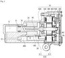
- FIG. 1 is a view illustrating a clutch actuator according to one exemplary embodiment of the present invention.
- FIG. 1 is a view clearly illustrating main features for a clear conceptual understanding of the present invention, and thus various modifications are expected and the scope of the present invention is not limited to specific shapes illustrated in the drawing.
- the clutch actuator may include a motor 10, a cover 20, a piston 30, and a lead screw 40.
- the motor 10 When the motor 10 is driven, the lead screw 40 rotates and the piston 30 linearly moves as the lead screw 40 rotates.
- An accommodation space S for a fluid is provided inside the cover 20, and the piston 30 is located in the accommodation space S.
- an inlet 21 and an outlet 22 in communication with the accommodation space S may be formed in the cover 20.
- a working fluid is supplied to the accommodation space S through the inlet 21, and the working fluid is discharged from the accommodation space S through the outlet 22.
- a working fluid pushed by the piston 30 and discharged through the outlet 22 may operate a clutch mounted on a vehicle.
- a displacement sensor magnet 50 may be installed at the lead screw 40.
- FIG. 2 is a view illustrating a motor illustrated in FIG. 1
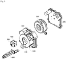
- FIG. 3 is an exploded view of the motor illustrated in FIG. 2
- FIG. 4 is a side cross-sectional view of the motor illustrated in FIG. 2 .
- FIGS. 2 to 4 are views clearly illustrating main features for a clear conceptual understanding of the present invention, and thus various modifications are expected and the scope of the present invention is not limited to specific shapes illustrated in the drawings.
- the motor 10 may include a housing 100, a control part 200, a stator assembly 300, a rotor 400, a rotary shaft 500, and a sensor connecting part 600.
- the housing 100 is formed in a cylindrical shape so that a space in which the stator assembly 300, the rotor 400, and the like may be installed is provided therein.
- the housing 100 is formed to be coupled to the cover 20.
- a shape or material of the housing 100 may be variously changed, a metal material capable of easily withstanding a high temperature may be selected for the housing 100 because the housing 100 is installed in a vehicle.
- one portion of the housing 100 that is, a front surface of the housing 100 connected to an actuator, may be made of aluminum.
- the entire housing 100 may be made of aluminum.
- the actuator may be coupled to a side of the front surface of the housing 100, and the control part 200 may be coupled to a side of a rear surface of the housing 100.
- a mounting slot 110 into which the sensor connecting part 600 is detachably inserted may be formed in the front surface of the housing 100.
- a center hole 111 forming a space in which the rotary shaft 500 is located and the lead screw 40 is connected to the rotary shaft 500 may be provide at the center of the housing 100, and the mounting slot 110 may be formed under the center hole 111.
- the control part 200 controls driving of the motor 10 on the basis of a state of the actuator transmitted from the sensor connecting part 600 and an external driving signal.
- a control part 200 may be integrally formed with the housing by being disposed at a rear of the housing 100 as a rear cover of the housing 100.
- FIG. 5 is a view illustrating a control part disposed on a rear surface of a housing.
- a housing terminal 120 may be provided on the rear surface of the housing 100.
- the housing terminal 120 may be disposed on a corner portion of the housing 100.
- the housing terminal 120 may be electrically connected to an external power source.
- a terminal insertion part 210 corresponding to such a housing terminal 120 may be formed on a corner portion of the control part 200.
- the control part 200 may be coupled to the rear surface of the housing 100 so that the housing terminal 120 is inserted into the terminal insertion part 210.
- the stator assembly 300 may include a stator core 300a (see FIG. 4 ), and a coil 300b (see FIG. 4 ) configured to form a rotating magnetic field may be wound around the stator core 300a.
- the coil 300b wound around the stator core 300a may be insulated by being surrounded by an insulator 300c (see FIG. 4 ).
- FIG. 6 is a view illustrating a stator assembly.
- the stator assembly 300 may be implemented to include a bus bar and a bearing therein.
- the stator assembly 300 may be formed by the stator core 300a (see FIG. 4 ), the coil 300b, and the insulator 300c being integrally molded together so that a power terminal 310 and a connecting terminal of a neutral terminal 320 are exposed to the outside.
- the stator assembly 300 may be formed by a bearing B2 being also integrally molded therewith together in a center thereof.
- a connecting terminal of one side of the power terminal 310 is extended in a radial direction to be fused and connected to the neutral terminal 320.
- a connecting terminal of the other side of the power terminal 310 may be formed to protrude upward to be directly connected to the control part 200.
- FIG. 7 is a view illustrating a stator assembly that is directly connected to a control part.
- power terminals 310 which protrude upward and have three phases may be assembled by being inserted into portions B of the control part 200 and then fixed at portions B by a soldering.
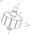
- FIG. 8 is a view illustrating a rotor.
- the rotor 400 is rotatably disposed inside the stator assembly 300.
- the rotor 400 is rotated by electromagnetic interaction with the stator assembly 300 due to a magnet 420 being mounted on a rotor core 410 thereof.
- a coil is wound around the stator assembly 300 so that the stator assembly 300 has a magnetic pole, and the rotor 400 is rotatable due to a magnetic field formed by the coil wound around the stator assembly 300.
- the rotary shaft 500 may be coupled to the center of the rotor 400. Accordingly, when the rotor 400 rotates, the rotary shaft 500 also rotates.
- the rotor 400 may be implemented to include the magnet 420 included in the rotor core 410 or to be attached to a circumferential surface of the rotor core 410 as illustrated in FIG. 8 .
- a sensor magnet 510 may be installed on a front end of one side of the rotary shaft 500.
- the sensor magnet 510 is for measuring a rotational speed of the motor 10.
- a spline groove 520 for connecting to the lead screw 40 (see FIG. 1 ) may be formed on a front end of the other end of the rotary shaft 500.
- the magnet 420 is mounted on the rotor core 410
- the sensor magnet 510 is mounted on the rotary shaft 500
- the rotor 400 coupled to the rotary shaft 500 may be formed by over-molding with plastic.
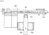
- FIG. 9 is a view illustrating a sensor magnet of a rotary shaft and a hall sensor of a control part disposed to face each other.
- a hall sensor 220 is provided at the control part 200, and the sensor magnet 510 is disposed to face the hall sensor 220.
- the control part 200 may directly measure the rotational speed of the motor 10 using the hall sensor 220.
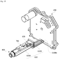
- FIG. 10 is a view illustrating a sensor connecting part that is connected to a control part.
- the sensor connecting part 600 serves to transmit measurement information of a sensor installed in front of the housing 100 in which the actuator is mounted to the control part 200 disposed at a rear of the housing 100.
- the sensor connecting part 600 serves to secure a sensing space in which a state of the actuator may be easily measured in front of the housing 100.
- Such a sensor connecting part 600 may include a body 610 and a terminal 620.
- the body 610 serves to spatially connect the front of the housing 100 at which sensors are located to the rear of the housing 100 at which the control part 200 is located.
- a body 610 may mainly include a first body 610A and a second body 610B.
- the first body 610A and the second body 610B may be connected to be stepped, and may be divided and described only according to shapes and functional features thereof but may be a single unit in which the first body 610A and the second body 610B are connected.
- the first body 610A and the second body 610B may be implemented as blocks having hexagonal shapes.
- the first body 610A is a portion exposed in front of the housing 100
- the second body 610B is a portion located in the housing 100.
- the sensor mounting part 61 is provided on the first body 610A.
- the sensor mounting part 611 includes a first mounting part 611a and a second mounting part 611b.
- the first mounting part 611a is disposed on an upper surface of the first body 610A to face the center of the rotary shaft 500.
- the first mounting part 611a is electrically connected to the terminal 620.
- a displacement sensor 700 may be mounted on the first mounting part 611a.
- the displacement sensor 700 may interact with the displacement sensor magnet 50 attached to the lead screw 40 to detect a position of the piston 30.
- the second mounting part 611b is disposed on a front end of the first body 610A. In addition, the second mounting part 611b is electrically connected to the terminal 620.
- the second mounting part 611b may be formed in a similar shape as the coupling slot 611ba (see FIG. 2 ) such that an inlet is formed to face forward.
- a pressure sensor 800 may be mounted on such a second mounting part 611b. As illustrated in FIG. 1 , the pressure sensor 800 is connected to the outlet 22 configured to discharge a working fluid to detect a hydraulic pressure applied to a clutch.
- the second body 610B may be located between the stator assembly 300 and an inner surface of the housing 100. Accordingly, a thickness of the second body 610B may be less than that of the first body 610A. In addition, the second body 610B may be physically connected to the control part 200.
- a connecting pin 610Ba connected to the terminal 620 and inserted into a connecting terminal of the control part 200 may be formed on an end of the second body 610B.
- the terminal 620 is disposed in the first body 610A and the second body 610B and is connected to the first mounting part 611a, the second mounting part 611b, and the connecting pin 610Ba. Such a terminal 620 transmits position information of the lead screw 40 measured by the displacement sensor 700 and pressure information of the working fluid measured by the pressure sensor 800 to the control part 200.
- Such a sensor connecting part 600 is detachably coupled to the housing 100 in a form in which the sensor connecting part 600 is inserted into the housing 100 and directly connected to the control part, and thus connects the sensors such as the displacement sensor 700 and the pressure sensor 800, to the control part 200 with a simple structure.
- the sensor connecting part 600 is located inside the cover 20 in a state of being mounted on the housing 100, dustproofing and waterproofing reliability can be improved.
Landscapes
- Engineering & Computer Science (AREA)
- Power Engineering (AREA)
- General Engineering & Computer Science (AREA)
- Microelectronics & Electronic Packaging (AREA)
- Physics & Mathematics (AREA)
- Mechanical Engineering (AREA)
- General Physics & Mathematics (AREA)
- Fluid Mechanics (AREA)
- Connection Of Motors, Electrical Generators, Mechanical Devices, And The Like (AREA)
Claims (14)
- Moteur (10) comprenant :un carter (100) ;une partie de commande (200) accouplée au carter (100) ;un ensemble stator (300) accouplé à un intérieur du carter (100) et relié à la partie de commande (200) ;un rotor (400) disposé à l'intérieur du stator (300) ;un arbre rotatif (500) accouplé au rotor ;(400) etune partie de liaison à capteur (600) incluant un corps (610) monté sur le carter (100) et ayant une partie de montage de capteur (611), et une borne (620) incluse dans le corps et reliée à la partie de montage de capteur (611) et à la partie de commande (200),dans lequel le corps (610) inclutun premier corps (610A) et un second corps (610B),dans lequel le premier corps (610A) est une portion exposée devant le carter et ayant la partie de montage de capteur (611),dans lequel le second corps (610B) est une portion située dans le carter (100) et est accouplé à la partie de commande (200),caractérisé en ce quela partie de montage de capteur (611) inclut une première partie de montage (611a) etune seconde partie de montage (611b) électriquement reliées à la borne,la première partie de montage (611a) étant disposée pour être tournée vers un centre de l'arbre rotatif (500) ; etla seconde partie de montage (611b) étant disposée sur une extrémité avant du corps de telle sorte qu'elle est électriquement reliée à la borne (620).
- Moteur selon la revendication 1, dans lequel la partie de commande (200) est disposée au niveau d'un arrière du carter (100).
- Moteur selon la revendication 1 ou 2, dans lequel la partie de liaison à capteur (600) comprend :un capteur de déplacement (700) monté sur la première partie de montage (611a) ; etun capteur de pression (800) monté sur la seconde partie de montage (611b).
- Moteur selon l'une quelconque des revendications précédentes, dans lequel la seconde partie de montage (611b) inclut une fente d'accouplement dans laquelle une entrée est formée pour être tournée vers l'avant.
- Moteur selon la revendication 1, dans lequel le carter (100) inclut une fente de montage (110),
dans lequel la partie de liaison à capteur (600) est accouplée de manière détachable à la fente de montage (110). - Moteur selon l'une quelconque des revendications précédentes, dans lequel le premier corps (610A) et le second corps (610B) sont accouplés pour être étagés.
- Moteur selon l'une quelconque des revendications précédentes, dans lequel une tige de liaison reliée à la borne et accouplée à la partie de commande (200) est formée sur une extrémité du second corps (610B).
- Moteur selon la revendication 1, dans lequel le second corps (610B) est disposé entre l'ensemble stator (300) et une surface intérieure du carter (100) et une épaisseur du second corps (610B) est inférieure à celle du premier corps (610A).
- Moteur selon l'une quelconque des revendications précédentes, dans lequel le rotor (400) est moulé d'un seul tenant avec et est accouplé à un premier aimant de capteur.
- Moteur selon l'une quelconque des revendications précédentes, dans lequel :un second aimant de capteur est accouplé à une extrémité arrière de l'arbre rotatif (500) ; etla partie de commande (200) inclut un capteur à effet Hall disposé pour être tournée vers le second aimant de capteur.
- Moteur selon l'une quelconque des revendications précédentes, dans lequel une borne d'alimentation, une borne neutre reliée à la borne d'alimentation et une bobine (300B), et un palier sont moulés d'un seul tenant pour former l'ensemble stator (300).
- Actionneur d'embrayage comprenant :un moteur (10) selon l'une quelconque des revendications précédentes ;un cache (20) incluant un cylindre ayant une entrée (21) et une sortie (22) ; etun piston (300) relié à l'arbre rotatif (500) du moteur (10) pour se déplacer en va-et-vient dans le cylindre.
- Actionneur d'embrayage selon la revendication 12, dans lequel le piston (30) inclut un aimant de capteur de déplacement ; et la partie de liaison à capteur (600) inclut un capteur de déplacement monté sur la première partie de montage.
- Actionneur d'embrayage selon la revendication 12 ou 13, comprenant en outre une vis-mère (40) configurée pour relier le piston (30) et l'arbre rotatif (500).
Applications Claiming Priority (2)
| Application Number | Priority Date | Filing Date | Title |
|---|---|---|---|
| KR1020140192403A KR102319204B1 (ko) | 2014-12-29 | 2014-12-29 | 모터 및 이를 포함하는 클러치 액츄에이터 |
| PCT/KR2015/008242 WO2016108379A1 (fr) | 2014-12-29 | 2015-08-06 | Moteur et actionneur d'embrayage le comprenant |
Publications (3)
| Publication Number | Publication Date |
|---|---|
| EP3242380A1 EP3242380A1 (fr) | 2017-11-08 |
| EP3242380A4 EP3242380A4 (fr) | 2018-07-25 |
| EP3242380B1 true EP3242380B1 (fr) | 2019-12-11 |
Family
ID=56284501
Family Applications (1)
| Application Number | Title | Priority Date | Filing Date |
|---|---|---|---|
| EP15875473.9A Active EP3242380B1 (fr) | 2014-12-29 | 2015-08-06 | Moteur et actionneur d'embrayage le comprenant |
Country Status (6)
| Country | Link |
|---|---|
| US (1) | US10644567B2 (fr) |
| EP (1) | EP3242380B1 (fr) |
| JP (1) | JP6793124B2 (fr) |
| KR (1) | KR102319204B1 (fr) |
| CN (1) | CN107148724B (fr) |
| WO (1) | WO2016108379A1 (fr) |
Families Citing this family (10)
| Publication number | Priority date | Publication date | Assignee | Title |
|---|---|---|---|---|
| US11067140B2 (en) * | 2017-05-03 | 2021-07-20 | Schaeffler Technologies AG & Co. KG | Method for operating an actuator arrangement for a clutch operating system, and actuator arrangement |
| WO2019001652A1 (fr) * | 2017-06-28 | 2019-01-03 | Linak A/S | Actionneur linéaire |
| KR102510334B1 (ko) * | 2017-08-03 | 2023-03-15 | 엘지이노텍 주식회사 | 로터 및 이를 포함하는 모터 |
| CN111095737B (zh) * | 2017-08-03 | 2022-08-30 | Lg伊诺特有限公司 | 转子和包括该转子的电机 |
| DE102018219979A1 (de) * | 2018-11-22 | 2020-05-28 | Robert Bosch Gmbh | Elektromotorische Antriebeinrichtung, Bremsaktuator |
| CN110868013B (zh) * | 2019-10-24 | 2021-06-08 | 深圳帆美智能科技有限公司 | 一种直线作动器及其控制方法 |
| KR102116859B1 (ko) * | 2019-12-27 | 2020-05-29 | 주식회사 컨트로맥스 | 항공기용 전기식 구동장치의 지터현상 방지 시스템 |
| NO347355B1 (no) * | 2020-11-24 | 2023-09-25 | Electrical Subsea & Drilling As | Anordning ved aktuator |
| WO2022114961A1 (fr) * | 2020-11-24 | 2022-06-02 | Electrical Subsea & Drilling As | Dispositif actionneur |
| DE102021133952A1 (de) | 2021-12-21 | 2023-06-22 | Synapticon GmbH | Motorvorrichtung mit einer multifunktionalen Zwischeneinheit, die zwischen einer Motoreinheit und einer Servoantriebseinheit der Motorvorrichtung angeordnet ist |
Family Cites Families (27)
| Publication number | Priority date | Publication date | Assignee | Title |
|---|---|---|---|---|
| JP2862053B2 (ja) | 1993-04-02 | 1999-02-24 | 三菱電機株式会社 | 駆動制御装置付モータ |
| JP3040052B2 (ja) | 1994-05-09 | 2000-05-08 | 株式会社フジユニバンス | トランスファ装置 |
| GB9619175D0 (en) * | 1996-09-13 | 1996-10-23 | Lucas Ind Plc | Electrical power-assisted steering systems |
| JPH10129445A (ja) | 1996-10-25 | 1998-05-19 | Nisshinbo Ind Inc | 液圧制御装置 |
| DE19701739A1 (de) * | 1997-01-20 | 1998-07-23 | Bosch Gmbh Robert | Stellvorrichtung |
| US6593674B2 (en) * | 2001-02-26 | 2003-07-15 | Woodward Governor Company | Vibration isolator and actuator incorporating same for isolating integral electronics |
| JP2005176526A (ja) | 2003-12-12 | 2005-06-30 | Nsk Ltd | 電動アクチュエータ |
| JP4615405B2 (ja) * | 2004-11-22 | 2011-01-19 | 日立オートモティブシステムズ株式会社 | モータ制御装置、パワーステアリング装置および制動力制御装置 |
| KR20060101609A (ko) | 2005-03-21 | 2006-09-26 | 임재옥 | 소형모터 감속기 |
| DE102007045815A1 (de) * | 2007-09-25 | 2009-04-09 | Magna Powertrain Ag & Co Kg | Getriebeeinheit |
| JP5195360B2 (ja) | 2008-01-24 | 2013-05-08 | 株式会社アドヴィックス | ブレーキ液圧制御装置 |
| KR200470310Y1 (ko) | 2008-12-15 | 2013-12-06 | 엘지이노텍 주식회사 | 차량용 조향장치의 센서 |
| DE112010004215A5 (de) | 2009-10-29 | 2012-08-23 | Schaeffler Technologies AG & Co. KG | Hydrostataktor |
| JP5417132B2 (ja) | 2009-11-26 | 2014-02-12 | Ntn株式会社 | 電動アクチュエータ |
| CN102118078A (zh) * | 2009-12-30 | 2011-07-06 | 德昌电机(深圳)有限公司 | 电机驱动组件 |
| DE112011101281B4 (de) * | 2010-04-12 | 2022-03-03 | Schaeffler Technologies AG & Co. KG | Hydrostataktor |
| EP2580850B1 (fr) * | 2010-06-14 | 2021-11-10 | Black & Decker, Inc. | Unité de commande pour moteur sans balais dans un outil électrique |
| JP2012147519A (ja) * | 2011-01-07 | 2012-08-02 | Mitsuba Corp | モータ装置 |
| JP5775853B2 (ja) * | 2011-11-16 | 2015-09-09 | 日本電産テクノモータ株式会社 | モールドモータ |
| US9190888B2 (en) | 2012-04-13 | 2015-11-17 | Globe Motors, Inc. | Method of positioning a sensor within a motor assembly |
| EA020935B1 (ru) * | 2012-05-11 | 2015-02-27 | Зао "Диаконт" | Электромеханический привод с демпфирующим устройством |
| DE102013201473A1 (de) | 2013-01-30 | 2014-07-31 | Schaeffler Technologies Gmbh & Co. Kg | Betätigungssystem für eine Kupplung eines Kraftfahrzeuges |
| US8985253B2 (en) * | 2013-02-05 | 2015-03-24 | Honda Motor Co., Ltd. | Generators and vehicles having auxiliary power generation systems |
| WO2015192040A1 (fr) * | 2014-06-13 | 2015-12-17 | Tolomatic, Inc. | Systèmes couplés de servomoteurs capacitif et magnétique |
| EP3206284A4 (fr) * | 2014-10-07 | 2018-10-03 | Nidec Sankyo Corporation | Moteur tubulaire, procédé de commande de moteur sans balai, et moteur avec frein |
| US10227872B2 (en) * | 2015-10-22 | 2019-03-12 | Nidec Motor Corporation | Internal bearing plate for gearmotor assembly |
| US20180062479A1 (en) * | 2016-08-24 | 2018-03-01 | Cts Corporation | Modular Vehicle Engine Component Actuator |
-
2014
- 2014-12-29 KR KR1020140192403A patent/KR102319204B1/ko active Active
-
2015
- 2015-08-06 EP EP15875473.9A patent/EP3242380B1/fr active Active
- 2015-08-06 CN CN201580071821.7A patent/CN107148724B/zh active Active
- 2015-08-06 WO PCT/KR2015/008242 patent/WO2016108379A1/fr not_active Ceased
- 2015-08-06 JP JP2017535438A patent/JP6793124B2/ja active Active
- 2015-08-06 US US15/540,945 patent/US10644567B2/en active Active
Non-Patent Citations (1)
| Title |
|---|
| None * |
Also Published As
| Publication number | Publication date |
|---|---|
| US10644567B2 (en) | 2020-05-05 |
| KR20160080503A (ko) | 2016-07-08 |
| WO2016108379A1 (fr) | 2016-07-07 |
| JP2018502546A (ja) | 2018-01-25 |
| EP3242380A1 (fr) | 2017-11-08 |
| EP3242380A4 (fr) | 2018-07-25 |
| CN107148724B (zh) | 2019-11-08 |
| US20170358970A1 (en) | 2017-12-14 |
| JP6793124B2 (ja) | 2020-12-02 |
| KR102319204B1 (ko) | 2021-10-29 |
| CN107148724A (zh) | 2017-09-08 |
Similar Documents
| Publication | Publication Date | Title |
|---|---|---|
| EP3242380B1 (fr) | Moteur et actionneur d'embrayage le comprenant | |
| US11201525B2 (en) | Motor and pump assembly for a brake system | |
| CN105993117B (zh) | 电机 | |
| EP1584908B1 (fr) | Détecteur de couple et son procédé de fabrication | |
| KR102146023B1 (ko) | 모터 및 이를 포함하는 전동식 조향장치 | |
| US20110273121A1 (en) | Electric Machine Component Temperature Monitoring | |
| CN103124666B (zh) | 包括电动机、控制单元和传感装置的转向器及配有转向器的电助力转向系统 | |
| JP2005273648A (ja) | 電動ポンプ | |
| US20230378852A1 (en) | Integrated axle drive and motor vehicle | |
| WO2016068073A1 (fr) | Dispositif d'entraînement | |
| US9531233B2 (en) | Motor connection module for suppressing connecting defects | |
| US11035696B2 (en) | Sensor arrangement having a modular structure including sensor mounted on bearing element configured to project from housing | |
| CN108662038B (zh) | 执行器及应用其的电子离合器系统 | |
| JP4475710B2 (ja) | 直線駆動装置 | |
| CN111226384B (zh) | 电气的机动车流体泵 | |
| EP3403320B1 (fr) | Pompe fluidique électrique d'automobile | |
| CN109891721A (zh) | 电动机 | |
| CN117200505B (zh) | 振镜电机 | |
| CN103855888A (zh) | 线性马达 | |
| JP7158457B2 (ja) | アキシアル・ピストン・ポンプ | |
| CN105840579A (zh) | 流体操作装置 | |
| CN114079356A (zh) | 具有位置传感器的旋转机器 | |
| EP4729394A1 (fr) | Appareil de direction avec système de capteur innovant et procédé de commande associé | |
| CN223713772U (zh) | 转子位置感应装置及电机设备 | |
| KR102361356B1 (ko) | 변위 측정 장치 및 이를 포함하는 모터 |
Legal Events
| Date | Code | Title | Description |
|---|---|---|---|
| STAA | Information on the status of an ep patent application or granted ep patent |
Free format text: STATUS: THE INTERNATIONAL PUBLICATION HAS BEEN MADE |
|
| PUAI | Public reference made under article 153(3) epc to a published international application that has entered the european phase |
Free format text: ORIGINAL CODE: 0009012 |
|
| STAA | Information on the status of an ep patent application or granted ep patent |
Free format text: STATUS: REQUEST FOR EXAMINATION WAS MADE |
|
| 17P | Request for examination filed |
Effective date: 20170629 |
|
| AK | Designated contracting states |
Kind code of ref document: A1 Designated state(s): AL AT BE BG CH CY CZ DE DK EE ES FI FR GB GR HR HU IE IS IT LI LT LU LV MC MK MT NL NO PL PT RO RS SE SI SK SM TR |
|
| AX | Request for extension of the european patent |
Extension state: BA ME |
|
| DAV | Request for validation of the european patent (deleted) | ||
| DAX | Request for extension of the european patent (deleted) | ||
| A4 | Supplementary search report drawn up and despatched |
Effective date: 20180625 |
|
| RIC1 | Information provided on ipc code assigned before grant |
Ipc: H02K 17/32 20060101ALI20180619BHEP Ipc: F16H 25/20 20060101ALN20180619BHEP Ipc: H02K 7/11 20060101ALI20180619BHEP Ipc: H02K 11/20 20160101ALI20180619BHEP Ipc: H02K 7/116 20060101ALI20180619BHEP Ipc: F16D 29/00 20060101ALI20180619BHEP Ipc: H02K 11/00 20160101AFI20180619BHEP Ipc: H02K 7/06 20060101ALN20180619BHEP Ipc: F15B 7/08 20060101ALN20180619BHEP Ipc: H02K 5/22 20060101ALI20180619BHEP Ipc: H02K 11/38 20160101ALI20180619BHEP Ipc: H02K 7/108 20060101ALI20180619BHEP |
|
| RIC1 | Information provided on ipc code assigned before grant |
Ipc: H02K 11/38 20160101ALI20190520BHEP Ipc: H02K 7/11 20060101ALI20190520BHEP Ipc: F16H 25/20 20060101ALN20190520BHEP Ipc: G01D 5/14 20060101ALN20190520BHEP Ipc: H02K 11/20 20160101ALI20190520BHEP Ipc: H02K 7/108 20060101ALI20190520BHEP Ipc: H02K 7/116 20060101ALI20190520BHEP Ipc: H02K 11/215 20160101ALI20190520BHEP Ipc: H02K 17/32 20060101ALI20190520BHEP Ipc: H02K 11/00 20160101AFI20190520BHEP Ipc: F16D 29/00 20060101ALI20190520BHEP Ipc: H02K 11/33 20160101ALI20190520BHEP Ipc: H02K 7/06 20060101ALN20190520BHEP Ipc: F16D 25/08 20060101ALI20190520BHEP Ipc: H02K 5/22 20060101ALI20190520BHEP Ipc: F15B 7/08 20060101ALN20190520BHEP |
|
| GRAP | Despatch of communication of intention to grant a patent |
Free format text: ORIGINAL CODE: EPIDOSNIGR1 |
|
| STAA | Information on the status of an ep patent application or granted ep patent |
Free format text: STATUS: GRANT OF PATENT IS INTENDED |
|
| INTG | Intention to grant announced |
Effective date: 20190703 |
|
| GRAS | Grant fee paid |
Free format text: ORIGINAL CODE: EPIDOSNIGR3 |
|
| GRAA | (expected) grant |
Free format text: ORIGINAL CODE: 0009210 |
|
| STAA | Information on the status of an ep patent application or granted ep patent |
Free format text: STATUS: THE PATENT HAS BEEN GRANTED |
|
| AK | Designated contracting states |
Kind code of ref document: B1 Designated state(s): AL AT BE BG CH CY CZ DE DK EE ES FI FR GB GR HR HU IE IS IT LI LT LU LV MC MK MT NL NO PL PT RO RS SE SI SK SM TR |
|
| REG | Reference to a national code |
Ref country code: GB Ref legal event code: FG4D |
|
| REG | Reference to a national code |
Ref country code: CH Ref legal event code: EP |
|
| REG | Reference to a national code |
Ref country code: AT Ref legal event code: REF Ref document number: 1213164 Country of ref document: AT Kind code of ref document: T Effective date: 20191215 |
|
| REG | Reference to a national code |
Ref country code: DE Ref legal event code: R096 Ref document number: 602015043646 Country of ref document: DE |
|
| REG | Reference to a national code |
Ref country code: IE Ref legal event code: FG4D |
|
| REG | Reference to a national code |
Ref country code: NL Ref legal event code: MP Effective date: 20191211 |
|
| REG | Reference to a national code |
Ref country code: LT Ref legal event code: MG4D |
|
| PG25 | Lapsed in a contracting state [announced via postgrant information from national office to epo] |
Ref country code: NO Free format text: LAPSE BECAUSE OF FAILURE TO SUBMIT A TRANSLATION OF THE DESCRIPTION OR TO PAY THE FEE WITHIN THE PRESCRIBED TIME-LIMIT Effective date: 20200311 Ref country code: GR Free format text: LAPSE BECAUSE OF FAILURE TO SUBMIT A TRANSLATION OF THE DESCRIPTION OR TO PAY THE FEE WITHIN THE PRESCRIBED TIME-LIMIT Effective date: 20200312 Ref country code: BG Free format text: LAPSE BECAUSE OF FAILURE TO SUBMIT A TRANSLATION OF THE DESCRIPTION OR TO PAY THE FEE WITHIN THE PRESCRIBED TIME-LIMIT Effective date: 20200311 Ref country code: FI Free format text: LAPSE BECAUSE OF FAILURE TO SUBMIT A TRANSLATION OF THE DESCRIPTION OR TO PAY THE FEE WITHIN THE PRESCRIBED TIME-LIMIT Effective date: 20191211 Ref country code: LT Free format text: LAPSE BECAUSE OF FAILURE TO SUBMIT A TRANSLATION OF THE DESCRIPTION OR TO PAY THE FEE WITHIN THE PRESCRIBED TIME-LIMIT Effective date: 20191211 Ref country code: LV Free format text: LAPSE BECAUSE OF FAILURE TO SUBMIT A TRANSLATION OF THE DESCRIPTION OR TO PAY THE FEE WITHIN THE PRESCRIBED TIME-LIMIT Effective date: 20191211 Ref country code: SE Free format text: LAPSE BECAUSE OF FAILURE TO SUBMIT A TRANSLATION OF THE DESCRIPTION OR TO PAY THE FEE WITHIN THE PRESCRIBED TIME-LIMIT Effective date: 20191211 |
|
| PG25 | Lapsed in a contracting state [announced via postgrant information from national office to epo] |
Ref country code: HR Free format text: LAPSE BECAUSE OF FAILURE TO SUBMIT A TRANSLATION OF THE DESCRIPTION OR TO PAY THE FEE WITHIN THE PRESCRIBED TIME-LIMIT Effective date: 20191211 Ref country code: RS Free format text: LAPSE BECAUSE OF FAILURE TO SUBMIT A TRANSLATION OF THE DESCRIPTION OR TO PAY THE FEE WITHIN THE PRESCRIBED TIME-LIMIT Effective date: 20191211 |
|
| PG25 | Lapsed in a contracting state [announced via postgrant information from national office to epo] |
Ref country code: AL Free format text: LAPSE BECAUSE OF FAILURE TO SUBMIT A TRANSLATION OF THE DESCRIPTION OR TO PAY THE FEE WITHIN THE PRESCRIBED TIME-LIMIT Effective date: 20191211 |
|
| PG25 | Lapsed in a contracting state [announced via postgrant information from national office to epo] |
Ref country code: PT Free format text: LAPSE BECAUSE OF FAILURE TO SUBMIT A TRANSLATION OF THE DESCRIPTION OR TO PAY THE FEE WITHIN THE PRESCRIBED TIME-LIMIT Effective date: 20200506 Ref country code: RO Free format text: LAPSE BECAUSE OF FAILURE TO SUBMIT A TRANSLATION OF THE DESCRIPTION OR TO PAY THE FEE WITHIN THE PRESCRIBED TIME-LIMIT Effective date: 20191211 Ref country code: CZ Free format text: LAPSE BECAUSE OF FAILURE TO SUBMIT A TRANSLATION OF THE DESCRIPTION OR TO PAY THE FEE WITHIN THE PRESCRIBED TIME-LIMIT Effective date: 20191211 Ref country code: ES Free format text: LAPSE BECAUSE OF FAILURE TO SUBMIT A TRANSLATION OF THE DESCRIPTION OR TO PAY THE FEE WITHIN THE PRESCRIBED TIME-LIMIT Effective date: 20191211 Ref country code: NL Free format text: LAPSE BECAUSE OF FAILURE TO SUBMIT A TRANSLATION OF THE DESCRIPTION OR TO PAY THE FEE WITHIN THE PRESCRIBED TIME-LIMIT Effective date: 20191211 Ref country code: EE Free format text: LAPSE BECAUSE OF FAILURE TO SUBMIT A TRANSLATION OF THE DESCRIPTION OR TO PAY THE FEE WITHIN THE PRESCRIBED TIME-LIMIT Effective date: 20191211 |
|
| PG25 | Lapsed in a contracting state [announced via postgrant information from national office to epo] |
Ref country code: SM Free format text: LAPSE BECAUSE OF FAILURE TO SUBMIT A TRANSLATION OF THE DESCRIPTION OR TO PAY THE FEE WITHIN THE PRESCRIBED TIME-LIMIT Effective date: 20191211 Ref country code: SK Free format text: LAPSE BECAUSE OF FAILURE TO SUBMIT A TRANSLATION OF THE DESCRIPTION OR TO PAY THE FEE WITHIN THE PRESCRIBED TIME-LIMIT Effective date: 20191211 Ref country code: IS Free format text: LAPSE BECAUSE OF FAILURE TO SUBMIT A TRANSLATION OF THE DESCRIPTION OR TO PAY THE FEE WITHIN THE PRESCRIBED TIME-LIMIT Effective date: 20200411 |
|
| REG | Reference to a national code |
Ref country code: DE Ref legal event code: R097 Ref document number: 602015043646 Country of ref document: DE |
|
| REG | Reference to a national code |
Ref country code: AT Ref legal event code: MK05 Ref document number: 1213164 Country of ref document: AT Kind code of ref document: T Effective date: 20191211 |
|
| PLBE | No opposition filed within time limit |
Free format text: ORIGINAL CODE: 0009261 |
|
| STAA | Information on the status of an ep patent application or granted ep patent |
Free format text: STATUS: NO OPPOSITION FILED WITHIN TIME LIMIT |
|
| PG25 | Lapsed in a contracting state [announced via postgrant information from national office to epo] |
Ref country code: DK Free format text: LAPSE BECAUSE OF FAILURE TO SUBMIT A TRANSLATION OF THE DESCRIPTION OR TO PAY THE FEE WITHIN THE PRESCRIBED TIME-LIMIT Effective date: 20191211 |
|
| 26N | No opposition filed |
Effective date: 20200914 |
|
| PG25 | Lapsed in a contracting state [announced via postgrant information from national office to epo] |
Ref country code: SI Free format text: LAPSE BECAUSE OF FAILURE TO SUBMIT A TRANSLATION OF THE DESCRIPTION OR TO PAY THE FEE WITHIN THE PRESCRIBED TIME-LIMIT Effective date: 20191211 Ref country code: AT Free format text: LAPSE BECAUSE OF FAILURE TO SUBMIT A TRANSLATION OF THE DESCRIPTION OR TO PAY THE FEE WITHIN THE PRESCRIBED TIME-LIMIT Effective date: 20191211 |
|
| PG25 | Lapsed in a contracting state [announced via postgrant information from national office to epo] |
Ref country code: IT Free format text: LAPSE BECAUSE OF FAILURE TO SUBMIT A TRANSLATION OF THE DESCRIPTION OR TO PAY THE FEE WITHIN THE PRESCRIBED TIME-LIMIT Effective date: 20191211 |
|
| PG25 | Lapsed in a contracting state [announced via postgrant information from national office to epo] |
Ref country code: PL Free format text: LAPSE BECAUSE OF FAILURE TO SUBMIT A TRANSLATION OF THE DESCRIPTION OR TO PAY THE FEE WITHIN THE PRESCRIBED TIME-LIMIT Effective date: 20191211 |
|
| PG25 | Lapsed in a contracting state [announced via postgrant information from national office to epo] |
Ref country code: MC Free format text: LAPSE BECAUSE OF FAILURE TO SUBMIT A TRANSLATION OF THE DESCRIPTION OR TO PAY THE FEE WITHIN THE PRESCRIBED TIME-LIMIT Effective date: 20191211 |
|
| REG | Reference to a national code |
Ref country code: CH Ref legal event code: PL |
|
| GBPC | Gb: european patent ceased through non-payment of renewal fee |
Effective date: 20200806 |
|
| PG25 | Lapsed in a contracting state [announced via postgrant information from national office to epo] |
Ref country code: LU Free format text: LAPSE BECAUSE OF NON-PAYMENT OF DUE FEES Effective date: 20200806 Ref country code: LI Free format text: LAPSE BECAUSE OF NON-PAYMENT OF DUE FEES Effective date: 20200831 Ref country code: CH Free format text: LAPSE BECAUSE OF NON-PAYMENT OF DUE FEES Effective date: 20200831 |
|
| REG | Reference to a national code |
Ref country code: BE Ref legal event code: MM Effective date: 20200831 |
|
| PG25 | Lapsed in a contracting state [announced via postgrant information from national office to epo] |
Ref country code: BE Free format text: LAPSE BECAUSE OF NON-PAYMENT OF DUE FEES Effective date: 20200831 Ref country code: IE Free format text: LAPSE BECAUSE OF NON-PAYMENT OF DUE FEES Effective date: 20200806 Ref country code: GB Free format text: LAPSE BECAUSE OF NON-PAYMENT OF DUE FEES Effective date: 20200806 |
|
| PG25 | Lapsed in a contracting state [announced via postgrant information from national office to epo] |
Ref country code: TR Free format text: LAPSE BECAUSE OF FAILURE TO SUBMIT A TRANSLATION OF THE DESCRIPTION OR TO PAY THE FEE WITHIN THE PRESCRIBED TIME-LIMIT Effective date: 20191211 Ref country code: MT Free format text: LAPSE BECAUSE OF FAILURE TO SUBMIT A TRANSLATION OF THE DESCRIPTION OR TO PAY THE FEE WITHIN THE PRESCRIBED TIME-LIMIT Effective date: 20191211 Ref country code: CY Free format text: LAPSE BECAUSE OF FAILURE TO SUBMIT A TRANSLATION OF THE DESCRIPTION OR TO PAY THE FEE WITHIN THE PRESCRIBED TIME-LIMIT Effective date: 20191211 |
|
| PG25 | Lapsed in a contracting state [announced via postgrant information from national office to epo] |
Ref country code: MK Free format text: LAPSE BECAUSE OF FAILURE TO SUBMIT A TRANSLATION OF THE DESCRIPTION OR TO PAY THE FEE WITHIN THE PRESCRIBED TIME-LIMIT Effective date: 20191211 |
|
| PGFP | Annual fee paid to national office [announced via postgrant information from national office to epo] |
Ref country code: DE Payment date: 20250721 Year of fee payment: 11 |
|
| PGFP | Annual fee paid to national office [announced via postgrant information from national office to epo] |
Ref country code: FR Payment date: 20250725 Year of fee payment: 11 |