EP3242700B1 - Unité d'aiguille avec une protection d'aiguille verrouillable et dispositif d'injection comprenant une telle unité d'aiguille - Google Patents
Unité d'aiguille avec une protection d'aiguille verrouillable et dispositif d'injection comprenant une telle unité d'aiguille Download PDFInfo
- Publication number
- EP3242700B1 EP3242700B1 EP16700545.3A EP16700545A EP3242700B1 EP 3242700 B1 EP3242700 B1 EP 3242700B1 EP 16700545 A EP16700545 A EP 16700545A EP 3242700 B1 EP3242700 B1 EP 3242700B1
- Authority
- EP
- European Patent Office
- Prior art keywords
- needle
- shield
- hub
- unit
- locking
- Prior art date
- Legal status (The legal status is an assumption and is not a legal conclusion. Google has not performed a legal analysis and makes no representation as to the accuracy of the status listed.)
- Not-in-force
Links
Images


Classifications
-
- A—HUMAN NECESSITIES
- A61—MEDICAL OR VETERINARY SCIENCE; HYGIENE
- A61M—DEVICES FOR INTRODUCING MEDIA INTO, OR ONTO, THE BODY; DEVICES FOR TRANSDUCING BODY MEDIA OR FOR TAKING MEDIA FROM THE BODY; DEVICES FOR PRODUCING OR ENDING SLEEP OR STUPOR
- A61M5/00—Devices for bringing media into the body in a subcutaneous, intra-vascular or intramuscular way; Accessories therefor, e.g. filling or cleaning devices, arm-rests
- A61M5/002—Packages specially adapted therefor, e.g. for syringes or needles, kits for diabetics
-
- A—HUMAN NECESSITIES
- A61—MEDICAL OR VETERINARY SCIENCE; HYGIENE
- A61M—DEVICES FOR INTRODUCING MEDIA INTO, OR ONTO, THE BODY; DEVICES FOR TRANSDUCING BODY MEDIA OR FOR TAKING MEDIA FROM THE BODY; DEVICES FOR PRODUCING OR ENDING SLEEP OR STUPOR
- A61M5/00—Devices for bringing media into the body in a subcutaneous, intra-vascular or intramuscular way; Accessories therefor, e.g. filling or cleaning devices, arm-rests
- A61M5/178—Syringes
- A61M5/31—Details
- A61M5/32—Needles; Details of needles pertaining to their connection with syringe or hub; Accessories for bringing the needle into, or holding the needle on, the body; Devices for protection of needles
- A61M5/3202—Devices for protection of the needle before use, e.g. caps
-
- A—HUMAN NECESSITIES
- A61—MEDICAL OR VETERINARY SCIENCE; HYGIENE
- A61M—DEVICES FOR INTRODUCING MEDIA INTO, OR ONTO, THE BODY; DEVICES FOR TRANSDUCING BODY MEDIA OR FOR TAKING MEDIA FROM THE BODY; DEVICES FOR PRODUCING OR ENDING SLEEP OR STUPOR
- A61M5/00—Devices for bringing media into the body in a subcutaneous, intra-vascular or intramuscular way; Accessories therefor, e.g. filling or cleaning devices, arm-rests
- A61M5/178—Syringes
- A61M5/31—Details
- A61M5/32—Needles; Details of needles pertaining to their connection with syringe or hub; Accessories for bringing the needle into, or holding the needle on, the body; Devices for protection of needles
- A61M5/3205—Apparatus for removing or disposing of used needles or syringes, e.g. containers; Means for protection against accidental injuries from used needles
- A61M5/321—Means for protection against accidental injuries by used needles
- A61M5/3243—Means for protection against accidental injuries by used needles being axially-extensible, e.g. protective sleeves coaxially slidable on the syringe barrel
- A61M5/326—Fully automatic sleeve extension, i.e. in which triggering of the sleeve does not require a deliberate action by the user
-
- A—HUMAN NECESSITIES
- A61—MEDICAL OR VETERINARY SCIENCE; HYGIENE
- A61M—DEVICES FOR INTRODUCING MEDIA INTO, OR ONTO, THE BODY; DEVICES FOR TRANSDUCING BODY MEDIA OR FOR TAKING MEDIA FROM THE BODY; DEVICES FOR PRODUCING OR ENDING SLEEP OR STUPOR
- A61M5/00—Devices for bringing media into the body in a subcutaneous, intra-vascular or intramuscular way; Accessories therefor, e.g. filling or cleaning devices, arm-rests
- A61M5/178—Syringes
- A61M5/31—Details
- A61M5/32—Needles; Details of needles pertaining to their connection with syringe or hub; Accessories for bringing the needle into, or holding the needle on, the body; Devices for protection of needles
- A61M5/3293—Needles; Details of needles pertaining to their connection with syringe or hub; Accessories for bringing the needle into, or holding the needle on, the body; Devices for protection of needles characterised by features of the needle hub
-
- A—HUMAN NECESSITIES
- A61—MEDICAL OR VETERINARY SCIENCE; HYGIENE
- A61M—DEVICES FOR INTRODUCING MEDIA INTO, OR ONTO, THE BODY; DEVICES FOR TRANSDUCING BODY MEDIA OR FOR TAKING MEDIA FROM THE BODY; DEVICES FOR PRODUCING OR ENDING SLEEP OR STUPOR
- A61M5/00—Devices for bringing media into the body in a subcutaneous, intra-vascular or intramuscular way; Accessories therefor, e.g. filling or cleaning devices, arm-rests
- A61M5/178—Syringes
- A61M5/24—Ampoule syringes, i.e. syringes with needle for use in combination with replaceable ampoules or carpules, e.g. automatic
- A61M5/2455—Ampoule syringes, i.e. syringes with needle for use in combination with replaceable ampoules or carpules, e.g. automatic with sealing means to be broken or opened
- A61M5/2466—Ampoule syringes, i.e. syringes with needle for use in combination with replaceable ampoules or carpules, e.g. automatic with sealing means to be broken or opened by piercing without internal pressure increase
- A61M2005/247—Ampoule syringes, i.e. syringes with needle for use in combination with replaceable ampoules or carpules, e.g. automatic with sealing means to be broken or opened by piercing without internal pressure increase with fixed or steady piercing means, e.g. piercing under movement of ampoule
-
- A—HUMAN NECESSITIES
- A61—MEDICAL OR VETERINARY SCIENCE; HYGIENE
- A61M—DEVICES FOR INTRODUCING MEDIA INTO, OR ONTO, THE BODY; DEVICES FOR TRANSDUCING BODY MEDIA OR FOR TAKING MEDIA FROM THE BODY; DEVICES FOR PRODUCING OR ENDING SLEEP OR STUPOR
- A61M5/00—Devices for bringing media into the body in a subcutaneous, intra-vascular or intramuscular way; Accessories therefor, e.g. filling or cleaning devices, arm-rests
- A61M5/178—Syringes
- A61M5/31—Details
- A61M5/32—Needles; Details of needles pertaining to their connection with syringe or hub; Accessories for bringing the needle into, or holding the needle on, the body; Devices for protection of needles
- A61M5/3205—Apparatus for removing or disposing of used needles or syringes, e.g. containers; Means for protection against accidental injuries from used needles
- A61M5/321—Means for protection against accidental injuries by used needles
- A61M5/3243—Means for protection against accidental injuries by used needles being axially-extensible, e.g. protective sleeves coaxially slidable on the syringe barrel
- A61M5/3245—Constructional features thereof, e.g. to improve manipulation or functioning
- A61M2005/3247—Means to impede repositioning of protection sleeve from needle covering to needle uncovering position
-
- A—HUMAN NECESSITIES
- A61—MEDICAL OR VETERINARY SCIENCE; HYGIENE
- A61M—DEVICES FOR INTRODUCING MEDIA INTO, OR ONTO, THE BODY; DEVICES FOR TRANSDUCING BODY MEDIA OR FOR TAKING MEDIA FROM THE BODY; DEVICES FOR PRODUCING OR ENDING SLEEP OR STUPOR
- A61M5/00—Devices for bringing media into the body in a subcutaneous, intra-vascular or intramuscular way; Accessories therefor, e.g. filling or cleaning devices, arm-rests
- A61M5/178—Syringes
- A61M5/31—Details
- A61M5/32—Needles; Details of needles pertaining to their connection with syringe or hub; Accessories for bringing the needle into, or holding the needle on, the body; Devices for protection of needles
- A61M5/3205—Apparatus for removing or disposing of used needles or syringes, e.g. containers; Means for protection against accidental injuries from used needles
- A61M5/321—Means for protection against accidental injuries by used needles
- A61M5/3243—Means for protection against accidental injuries by used needles being axially-extensible, e.g. protective sleeves coaxially slidable on the syringe barrel
- A61M5/3245—Constructional features thereof, e.g. to improve manipulation or functioning
- A61M2005/3254—Shielding of proximal needles, e.g. for pen needles
-
- A—HUMAN NECESSITIES
- A61—MEDICAL OR VETERINARY SCIENCE; HYGIENE
- A61M—DEVICES FOR INTRODUCING MEDIA INTO, OR ONTO, THE BODY; DEVICES FOR TRANSDUCING BODY MEDIA OR FOR TAKING MEDIA FROM THE BODY; DEVICES FOR PRODUCING OR ENDING SLEEP OR STUPOR
- A61M5/00—Devices for bringing media into the body in a subcutaneous, intra-vascular or intramuscular way; Accessories therefor, e.g. filling or cleaning devices, arm-rests
- A61M5/178—Syringes
- A61M5/31—Details
- A61M5/32—Needles; Details of needles pertaining to their connection with syringe or hub; Accessories for bringing the needle into, or holding the needle on, the body; Devices for protection of needles
- A61M5/3205—Apparatus for removing or disposing of used needles or syringes, e.g. containers; Means for protection against accidental injuries from used needles
- A61M5/321—Means for protection against accidental injuries by used needles
- A61M5/3243—Means for protection against accidental injuries by used needles being axially-extensible, e.g. protective sleeves coaxially slidable on the syringe barrel
- A61M5/326—Fully automatic sleeve extension, i.e. in which triggering of the sleeve does not require a deliberate action by the user
- A61M2005/3267—Biased sleeves where the needle is uncovered by insertion of the needle into a patient's body
-
- A—HUMAN NECESSITIES
- A61—MEDICAL OR VETERINARY SCIENCE; HYGIENE
- A61M—DEVICES FOR INTRODUCING MEDIA INTO, OR ONTO, THE BODY; DEVICES FOR TRANSDUCING BODY MEDIA OR FOR TAKING MEDIA FROM THE BODY; DEVICES FOR PRODUCING OR ENDING SLEEP OR STUPOR
- A61M2207/00—Methods of manufacture, assembly or production
-
- A—HUMAN NECESSITIES
- A61—MEDICAL OR VETERINARY SCIENCE; HYGIENE
- A61M—DEVICES FOR INTRODUCING MEDIA INTO, OR ONTO, THE BODY; DEVICES FOR TRANSDUCING BODY MEDIA OR FOR TAKING MEDIA FROM THE BODY; DEVICES FOR PRODUCING OR ENDING SLEEP OR STUPOR
- A61M5/00—Devices for bringing media into the body in a subcutaneous, intra-vascular or intramuscular way; Accessories therefor, e.g. filling or cleaning devices, arm-rests
- A61M5/178—Syringes
- A61M5/20—Automatic syringes, e.g. with automatically actuated piston rod, with automatic needle injection, filling automatically
- A61M5/2033—Spring-loaded one-shot injectors with or without automatic needle insertion
-
- A—HUMAN NECESSITIES
- A61—MEDICAL OR VETERINARY SCIENCE; HYGIENE
- A61M—DEVICES FOR INTRODUCING MEDIA INTO, OR ONTO, THE BODY; DEVICES FOR TRANSDUCING BODY MEDIA OR FOR TAKING MEDIA FROM THE BODY; DEVICES FOR PRODUCING OR ENDING SLEEP OR STUPOR
- A61M5/00—Devices for bringing media into the body in a subcutaneous, intra-vascular or intramuscular way; Accessories therefor, e.g. filling or cleaning devices, arm-rests
- A61M5/178—Syringes
- A61M5/24—Ampoule syringes, i.e. syringes with needle for use in combination with replaceable ampoules or carpules, e.g. automatic
- A61M5/2455—Ampoule syringes, i.e. syringes with needle for use in combination with replaceable ampoules or carpules, e.g. automatic with sealing means to be broken or opened
- A61M5/2466—Ampoule syringes, i.e. syringes with needle for use in combination with replaceable ampoules or carpules, e.g. automatic with sealing means to be broken or opened by piercing without internal pressure increase
Definitions
- the present invention relates to a needle unit with a lockable needle shield for cooperation with an injection device for injecting a medicament.
- medicament is meant to encompass any flowable drug capable of being passed through a delivery means such as a hollow needle or cannula in a controlled manner.
- flowable drugs are a liquid, a solution, a gel or a fine suspension.
- lyophilized drugs which prior to administration are dissolved into a liquid form are encompassed by the above definition.
- Representative medicaments includes for example pharmaceuticals, peptides, proteins (e.g. insulin, insulin analogues and C-peptide), hormones, biologically derived or active agents, hormonal and gene based agents, nutritional formulas and other substances in both solid (dispensed) or liquid form.
- the needle Prior to the actual use of the device by an end user, the needle must be assembled with the injection device. It is desired that the user does not need to handle the needle at all which requires pre-mounting of the needle with the injection device. Prior to mounting the needle on the injection device, a number of additional process steps are typically required, for example sterilization of the needle itself. It is therefore desired to provide a needle unit which is easy to handle prior to being mounted on the injection device without risking injury to people handling the needle unit and without risking damage to the needle.
- the needle is protected by a penetrable cover element, for example a silicone foil like cover element, which maintains a sterile barrier around the needle itself.
- a penetrable cover element for example a silicone foil like cover element, which maintains a sterile barrier around the needle itself.
- This flexible cover element is typically not so strong and can be easily damaged. It is therefore desired to protect the flexible cover element during handling to avoid damage to the cover which could destroy the sterile barrier effect of the cover.
- a needle shield is therefore often arranged to encase the needle and any cover elements which ensure the sterility of the needle.
- the needle shield is often assembled together with the needle to form a needle unit.
- the shield element is locked in position with respect to the needle.
- the needle When the needle is to be mounted on the injection device, the shield element needs to be removed from the needle or the needle shield needs to be unlocked so that the needle shield can be displaced with respect to the needle so as to expose the needle.
- This needle unit is a complex unit comprising a number of elements including a spring.
- the needle unit is intended for insertion into a rigid and sterile container for maintaining sterility during storing and handling. Typically such containers are sealed off by a planar seal that needs to be manually peeled off prior to mounting of the needle unit on an injection device.
- Such needle unit is not easily incorporated into an injection device at the time of manufacture.
- each injection needle having a pair of needle sheaths mounted to the needle, is inserted into a sterilizing compartment to form a needle cannula assembly which allows subsequent sterilization, such as by steam sterilization of the entire needle cannula assembly.
- the sterilizing compartment may serve as a needle shield relative to which the injection needle is movable for rendering access to the tip of the front needle cannula part.
- a needle unit and an injection device comprising a needle unit that are improved with regards to locking of the needle shield prior to mounting of the needle unit on the injection device and unlocking the needle shield during/after mounting of the needle unit on the injection device.
- Yet additional further objects of the invention are to provide measures for obtaining needle units and injection devices having a superior performance and, at the same time, enabling manufacture at a reduced cost.
- the present invention relates to a needle unit as defined in claim 1.
- distal and proximal are used to describe the placement of the different elements with respect to each other.
- distal end should be understood as being the end which is closest to the skin of the user during injection while the term proximal end should be understood as the end which is farthest from the skin of the user during injection.
- proximal end should be understood as the end which is farthest from the skin of the user during injection.
- the user will hold the proximal end of the device while placing the distal end of the device on the skin during injection.
- displacement in a distal direction refers to motion which is arranged in a direction which is defined by a vector pointing from the proximal end to the distal end of the device.
- displacement in a proximal direction refers to motion which is arranged in a direction which is defined by a vector pointing from the distal end to the proximal end of the device.
- shock proof lock should be understood as a locking mechanism which cannot be accidentally opened by subjecting the locking mechanism to a shock load.
- a friction press fit lock would not be a shock proof locking mechanism since a shock in the right direction could cause the elements to disengage with each other.
- the needle unit further comprises a pierceable distal cover element forming a sterility seal that seals off the needle at portions distal to the needle hub.
- the needle unit further comprises a pierceable proximal cover element forming a sterility seal that seals off the needle at portions proximal to the needle hub.
- the cover elements may be made of a material that enables damp sterilisation of the entire needle unit in its assembled state, such as damp sterilisation.
- Each of the distal cover element and the proximal cover element may be configured as a collapsible penetrable boot that, when an axially compression force acts on the cover element, collapses axially causing the needle to pierce and penetrate the cover element.
- the needle hub and the needle shield are manufactured as injection moulded components and the first hub locking element and the first shield locking element are integrated elements of the injection moulded components.
- the second hub and second shield locking elements could also be integrated into the injection moulded components.
- the releasable first locking mechanism and the second locking mechanism are arranged as two independent locking mechanisms. In this way, the action of the two locking mechanisms can be separated into two separate functions.
- the releasable first locking mechanism and the second locking mechanism could be integrated into a single mechanism.
- the end of the flexible arm instead of an arm with a free end which engages with an end surface of a slot as shown in the current embodiments, the end of the flexible arm could be formed as a hook which engages with a corresponding groove in the side of a slot in the shield element to prevent motion of the needle hub both in a distal and in a proximal direction with respect to the shield element.
- the needle hub and the needle shield are prevented from rotating with respect to each other around the longitudinal axis of the needle. In this way, respective motion of the needle shield and the needle hub along the longitudinal axis of the needle can be used to force elements of the needle shield/needle hub to displace sideways without simultaneous rotation of the two elements.
- the releasable first locking mechanism and/or the second locking mechanism are arranged proximally to the proximal end of the needle. In this way, the front end of the device where the needle is placed can be made simpler while the locking mechanisms are placed behind the needle where there is more room.
- the needle shield may be arranged coaxially with the needle hub.
- the needle shield surrounds all parts of the needle hub.
- the needle hub may comprise elements located radially inwards relative to the needle shield while having other elements that extend radially exterior to the needle shield.
- the releasable first locking mechanism assumes a state wherein the needle unit is in an unlocked state.
- the needle unit In the unlocked state, movement of the needle hub is enabled for displacement in the distal direction relative to the needle shield.
- the needle unit Prior to the needle unit is unlocked, the needle unit defines a locked state wherein no or only non-substantial relative axial displacement is possible between the needle shield and the needle hub.
- non-substantial relative axial displacement is defined as axial displacement which does not allow the cover elements to become penetrated by contact pressure of other needle units when like needle units are handled in bulk.
- each of the cover elements when present, may define a non-penetrated state wherein sterility of the needle is ensured.
- At least one displaced element or displaced portion of an element of the first hub locking element is configured to be moved when engaged with the lock release element of the injection device when the needle unit is coupled to the injection device.
- said displaced element or displaced portion of an element is moved to become unlocked, the movement occurs in an unlocking direction.
- Engaging surfaces between first hub locking element and the first shield locking element may be so formed that, upon an increase in a force exerted for displacing the needle shield proximally relative to the needle hub, the displaced element will be increasingly urged in a direction opposite the unlocking direction.
- the releasable first locking mechanism is unlocked via the outer side of the needle shield.
- the phrase "via the outer side” should be understood in the current specification as requiring an action which is performed on the outer side of the shield element.
- the locking mechanism is unlocked from the inside of the needle unit.
- this can be provided by providing an opening in the side of the needle shield through which the first locking mechanism is unlockable.
- the opening may be provided as a hole or as an elongated slot.
- the releasable first locking mechanism is arranged to automatically unlock when the needle unit is coupled to the housing of the injection device. In this way, the unlocking is arranged without any complicated actions being required during assembly of the injection device.
- the lock release element is a ramp element and the first hub locking element is arranged to be displaced by the ramp element to unlock the first locking mechanism when the needle unit is coupled to the injection device.
- one or both cooperating surfaces of the ramp element and the first hub locking element comprise surface elements that are inclined with respect to the longitudinal axis so as to impart a sideways force on the displaced element as the needle unit is displaced during coupling to the housing of the injection device.
- a free end of the displaced element moves in an unlocking direction.
- the first hub locking element and the first shield locking element may include engaging surface elements having a normal that is inclined with respect to the longitudinal axis, such as forming an angle less than 25 degrees relative to the longitudinal axis. Said engaging surface elements may be formed so that, when the needle unit assumes its locked state, upon an increase in force exerted for displacing the needle shield proximally relative to the needle hub, a free end of the displaced element will be increasingly urged in a direction opposite the unlocking direction.
- the first hub locking element or the first shield locking element is a flexible arm which is bendable about an axis which is perpendicular to the longitudinal axis of the needle and/or perpendicular to the outer surface of the needle hub and the lock release element is a ramp element with a ramp surface arranged on the inner surface of the housing and arranged to form an angle to the longitudinal axis of the needle of between 10 and 65 degrees, preferably between 10 and 45 degrees and even more preferably between 10 and 35 degrees.
- a non-claimed aspect of the invention relates to a method of manufacturing an injection device, the manufactured injection device comprising a needle shield having a proximal end and a distal end, a needle hub and a housing, said needle hub comprising a needle having a distal end, a proximal end and a longitudinal axis extending from the distal end to the proximal end, the needle hub and the needle shield being movable axially relative to each other for shifting the needle from a shielded state to an exposed state, said needle shield being arranged such that in the shielded state, the proximal end of the needle shield extends proximally past the proximal end of the needle and the distal end of the needle shield extends distally past the distal end of the needle and that in the exposed state the distal end of the needle extends distally past the distal end of the needle shield, the method comprising the steps of:
- the method further comprises the step of moving a second hub locking element of the needle hub relative to a second shield locking element of the needle shield to establish a second locking mechanism between the needle hub and the needle shield to prevent the needle hub from displacing relative to the needle shield in a proximal direction with respect to the needle shield.
- the step f) of assembling the needle unit with the housing comprises the step of releasing the releasable first locking mechanism by positioning the needle unit relative to the housing section whereby a release geometry or lock release element on the housing releases the releasable first locking mechanism.
- the releasable first locking mechanism is so configured that release of the releasable first locking mechanism requires relative movement of at least one of the first hub locking element and the first shield locking element in a direction which is not parallel with the longitudinal axis of the needle.
- said relative movement of at least one of the first hub locking element and the first shield locking element is configured for movement in a direction which is substantially perpendicular to the longitudinal axis of the needle, such as movement in a tangential direction around the longitudinal axis.
- the method further comprises the step, subsequent to step d), of sterilizing the needle unit.
- the needle shield fully protects the needle during the sterilizing procedure and the subsequent handling and assembling of the needle unit.
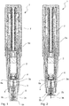
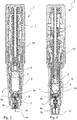
- Figures 1-4 show an example of an injection device in four different states of operation in order to explain the basic function of the device.
- the needle unit of the current invention can be used together with such an injection device, however the needle unit of the current invention can also be used with other forms of injection device. All the details of the injection device will not be described in detail since these details have already been described in other patent specifications of the current applicant, i.e.in WO 2015/150578 , WO 2015/197866 and WO 2015/197867 . Reference is made to these other specifications for additional details.
- Figures 1-4 show an injection device 1 with a medicament containing cartridge 2, a needle 3 having a proximal end 3a and a distal end 3b, a needle hub 4, a needle shield 5 having a proximal end 5a and a distal end 5b, a housing 6 and an activation mechanism 7.
- the details of the activation mechanism will not be covered in this specification since the needle unit of the current invention will work with many different types of activation mechanisms.
- the proximal end 5a of the needle shield is arranged proximally to the proximal end 3a of the needle.
- the distal end 5b of the needle shield is arranged distally to the distal end 3b of the needle.
- the needle shield is a single element which encases the needle completely.
- the needle shield could be arranged as a two component element whereby only the distal end of the needle shield would displace with respect to the needle shield, while the proximal end of the needle shield remains fixed in place relative to the needle.
- the needle 3 is arranged as a needle tube having two pointed ends, one arranged at the proximal end of the needle tube and one arranged at the distal end.
- the needle hub 4 grips the middle portion of the needle tube so that both the distal and the proximal ends of the needle are free.
- the proximal end of the needle is arranged to engage with a container 2 containing the medicament which is to be injected while the distal end is arranged to pierce the skin of the user to inject the medicament into the body of the user.
- the current invention could also be used in an embodiment of an injection device where the needle unit is arranged with only one pointed end and is connected to a source of medicament in another manner, without the use of a pierceable container as is shown in the current figures.
- the proximal end 3a of the needle is covered by a proximal cover element 8a forming a sterility sheath made from a thin flexible penetrable material, such as a foil like silicon cover element.
- the distal end of the needle is also covered by a distal cover element 8b forming a sterility sheath also made from a thin flexible penetrable material, such as a foil like silicon cover element.
- the cover elements are arranged to allow the needle to be sterilized, such as by steam sterilization, and then ensure that the needle itself is not contaminated by further handling of the needle unit.
- each of the distal and proximal cover elements are formed as generally cylindrical sheaths or boots that encircle and encapsulate the needle from the needle hub to the pointed needle end.
- the sterility sheaths in their non-penetrated state serve to maintain the needle in the sterile state right until use of the injection device.
- the needle shield 5 has been retracted with respect to the needle hub such that the distal end 3b of the needle now extends distally past the distal end 5b of the needle shield. In this way the distal end of the needle is now exposed and ready for injecting medicament into a user.
- the act of retracting the needle shield has caused the distal cover element 8b to be pulled back. This causes the distal end of the needle to pierce through the cover element thereby uncovering the distal end of the needle. Due to the flexible nature of the cover element, the cover element is easily retracted.
- the activation mechanism has pushed the medicament containing cartridge 2 forward in a distal direction to engage the cartridge with the proximal end of the needle.
- the proximal end of the needle punctures the lid/septum of the cartridge thereby establishing a fluid path from the cartridge through the needle and to the distal end of the needle whereby the medicament can be injected into the user.
- the proximal cover element 8a has also been compressed by the motion of the cartridge towards the needle. This causes the proximal end 3a of the needle to pierce and penetrate through the proximal cover element 8a thereby uncovering the proximal end of the needle allowing it to engage with the cartridge.
- the activation mechanism has pushed a piston 9 arranged in the cartridge downwards, thereby causing the medicament in the cartridge to be injected through the needle into the user.
- the needle shield is again pushed forward with respect to the needle hub to shield the distal end of the needle.
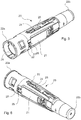
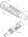
- FIGS 5 to 13 show different views of a first embodiment of a needle unit 20 according to the current invention and its components.
- the needle unit comprises a needle hub 21, a needle 23 and a needle shield 22.
- the needle hub grips the needle so that these components are fixedly attached to each other thus forming an injection needle assembly, see figures 12 and 13 .
- the needle 23 is formed as a needle tube with a proximal pointy end 23a and a distal pointy end 23b.
- Other embodiments may include a needle that is made by two cannula parts that are joined for fluid communication.
- the needle unit 20 may include cover elements forming penetrable sterility seals that seals off the proximal end 23a and the distal end 23b of the needle 23.
- cover elements will be further discussed in relation to the second embodiment of a needle unit shown in figures 14 to 20 . However, in figures 5 to 13 such cover elements are either not visible or not shown.
- both the needle shield and the needle hub are manufactured as injection moulded plastic components. Both elements are furthermore arranged as cylindrical and slightly tapered elements with a proximal end being wider than the distal end.
- the needle hub is arranged to be inserted into the proximal end of the needle shield during assembly.
- the needle shield and the needle hub are furthermore arranged such that the needle hub can slide back and forth inside the needle shield in a direction which is parallel to the longitudinal axis of the needle hub and the needle shield.
- the needle unit of the current invention therefore has locking mechanisms to lock the position of the needle hub with respect to the needle shield.
- two separate locking mechanisms are provided, a releasable first locking mechanism for ensuring that the needle hub does not displace in a distal direction with respect to the needle shield and a second mechanism for ensuring that the needle hub does not displace in a proximal direction with respect to the needle shield.
- the first locking mechanism is provided with a first hub locking element 24 fastened to the needle hub and a first shield locking element 25 fastened to the needle shield.
- the first hub locking element 24 is arranged as a flexible arm which is flexible about an axis which is perpendicular to the longitudinal axis of the needle hub and normal to the outer surface of the needle hub.
- the first shield locking element 25 is arranged as a stepped slot in the needle shield. When the needle hub is inserted into the needle shield, the free end of the flexible arm engages a first step of the stepped slot, thereby preventing further displacement of the needle hub distally with respect to the needle shield.
- the end of the flexible arm can be displaced by bending the arm to disengage the free end of the arm with the first step, i.e. in a direction which will be referenced "the unlocking direction", a direction which is counter to a direction which will be referenced “the locking direction”.
- the needle hub can be displaced further distally with respect to the needle shield, thereby exposing the needle as shown by comparing figures 12 and 13 .
- the second locking mechanism is provided with a ramped flexible flange 26 on the needle hub which is depressed slightly when inserting the needle hub into the needle shield.
- the ramped flange passes a cutout 27 in the needle shield and snaps outwardly, thereby preventing the needle hub from displacing in a proximal direction with respect to the needle shield.
- both the first and the second locking mechanisms are arranged as shock proof arrangements since the motion required to unlock the mechanisms and the motion required to displace the needle hub with respect to the needle shield are in different directions. For example, in order to retract the needle hub out of the needle shield, it would be required to simultaneously depress the two ramped flanges 26 on either side of the needle hub while also pulling the needle hub in a proximal direction. This would be impossible in a shock situation.
- the needle shield comprises two first shield locking elements, one arranged on each side of the needle shield. The same is true for the first hub locking elements and the second hub and shield locking elements. In this way, it is doubly ensured that the locking mechanisms do not open accidentally.
- the needle shield is provided with a groove 28 arranged parallel to the longitudinal axis of the needle shield which engages with an elongated protrusion 29 on the needle hub.
- a groove and an elongated protrusion is provided on both sides of the needle shield and needle hub respectively.
- the needle shield When the needle shield is assembled with the needle hub, it is desired that the needle shield cannot displace with respect to the needle hub during handling of the needle unit. Hence, the needle unit is in a locked state. In the shown embodiment, when the needle unit assumes the locked state, no or only little relative axial displacement between the needle shield and the needle hub is possible. In other embodiments, more relative axial displacement is possible, however to a degree where there is no risk that any of the cover elements becomes penetrated unintentionally.
- the needle shield is able to displace with respect to the needle hub so that the needle can become exposed when desired. It is therefore required to unlock the first locking mechanism. In the current embodiment, this is done automatically when the needle unit is inserted into the housing 30 of the injection device.
- the front portion of the housing 30 is also cylindrical with a slightly conical form where the proximal end is slightly larger than the distal end. The needle unit is inserted into the proximal end of the housing during assembly.
- a ramp element 31 provided on the inside surface of the housing 30 is arranged to automatically displace the free end of the flexible arm 24 of the needle hub sideways to disengage it with the stepped slot in the needle shield.
- the needle hub can then be displaced with respect to the needle shield.
- Ridges 32 on the needle shield engage with grooves 33 on either side of the ramp element 31 in order to prevent the needle shield from rotating with respect to the housing during insertion of the needle shield in the housing.
- Figure 9 shows the housing 30 where the ramp element 31 and the grooves 33 can easily be seen.
- Figures 10 and 11 show how the needle hub without the shield element has been inserted into the housing. It should be noted that during insertion in the real assembly procedure, the assembled needle unit with both the needle shield and the needle hub will be inserted. However for the sake of illustration, figure 10 and 11 show just the needle hub so that it is easier to see the interaction between the flexible arm 24 and the ramp element 31. In figure 10 , one can see the free end of the flexible arm 24 just engaging the end of the ramp element 31. As the needle hub is pressed further into the housing, the ramp element causes the free end of the flexible arm to be pushed more to the side as shown in figure 11 where the arm has been completely displaced to the side.
- Figure 12 and 13 now include the needle shield and the needle 23.
- the free end of the arm 24 has been pushed so far to the side, that it is no longer engaged with the end of the first step of the stepped slot 25.
- the needle shield can now be displaced further towards the proximal end of the device.
- the needle shield has been pushed towards the proximal end thereby exposing the distal end 23b of the needle 23.
- the free end of the flexible arm 24 has reached the bottom of the stepped slot and the needle shield cannot be displaced further in a proximal direction with respect to the needle hub.
- Figure 14 shows a cross sectional view of a second embodiment of a needle unit according to the invention. Relative to the previous views, figure 14 shows the needle unit 20 with two cover elements 8a and 8b attached to the hub 21 respectively covering the proximal end 23a and the distal end 23b of the needle cannula.
- Figure 14 shows the needle unit 20 after it has been assembled into the lower housing of housing 30 of the injection device and with a cartridge 2 being retained in a spaced apart configuration relative to the proximal end 23a of the needle, This state correspond to the storage state of the device.
- two resilient arms (referenced 530 in that disclosure) retain the cartridge and prevent the cartridge from being moved distally until point of use.
- Such resilient arms are also shown (non-referenced) in the appended drawings and thus serve to prevent the cartridge septum 2b and the rear cover element 8a from touching each other to prevent a potential premature penetration of these pierceable elements.
- the second embodiment of the needle unit 20 has mainly been modified relative to the first embodiment for ensuring increased robustness of the locking function relating to elements 24, 25 and ramp element 31 and to provide a more robust design in view of tolerances.
- Figure 15 shows a perspective view of the needle hub of the needle unit 20 of the second embodiment, but without the needle and cover elements being shown.
- a first hub locking element 24 is arranged as a flexible arm that extends generally parallel with the longitudinal axis.
- Flexible arm 24 is flexible about an axis which is perpendicular to the longitudinal axis of the needle hub and normal to the outer surface of the needle hub.
- the distal free end of the flexible arm is able to bend sideways in a tangential direction.
- Flexible arm at its distal free end includes a first surface 24a that is configured for cooperation with the ramp element 31 of the housing 30.
- the flexible arm includes a second surface 24b that is configured for cooperation with the first shield locking element 25 of the needle shield 22.
- the second surface 24b of flexible arm exhibits a surface that substantially faces the distal direction, i.e. having a normal substantially parallel with the longitudinal axis.
- the design of the first shield locking element 25 of the needle shield 22 has generally been maintained unchanged relative to the first embodiment.
- the surface 24b and the cooperating surface arranged on the stepped slot 25, i.e. the first step of the stepped slot, have been formed so that, when the needle unit assumes its locked state, upon an increase in force exerted for displacing the needle shield 22 proximally relative to the needle hub 21, the flexible arm will be increasingly urged in the locking direction, i.e. in the direction opposite the unlocking direction. In this position, the flexible arm extends generally parallel with the longitudinal axis.
- a robust locking mechanism is provided.
- Figure 16 shows a view of lower housing section 30 wherein ramp element 31 at its proximal end exhibits a surface 31a that is angled so as to interface with surface 24a of the flexible arm 24 of the needle hub 21.
- Surfaces 24a and 31a are formed with an inclination so as to impart a sideways force on the distal end of flexible arm 24 as the needle hub 21 is inserted distally relative to the housing 30.
- Figure 17 shows a perspective partial section view of the needle hub of figure 15 inserted into the housing of figure 16 in a locked position. Again, the needle shield, the needle and the cover elements are omitted from the view, cf. to fig. 10 .
- the free end of the flexible arm 24 just engaging the end of the ramp element 31, i.e. the first surface 24a engages surface 31a.
- the inclination of the first surface 24a of the flexible arm and the inclination of surface 31a of the ramp element 31 causes the free end of the flexible arm 24 to be pushed more to the side in the unlocking direction as shown in figure 18 where the arm has been completely displaced to the side.
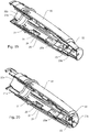
- Figure 19 and 20 now include the needle shield 22 and the needle 23.
- the free end of the arm 24 has been pushed so far to the side, that it is no longer engaged with the end of the first step of the stepped slot 25.
- the needle shield can now be displaced further towards the proximal end of the device.
- FIG 20 where the needle shield has been pushed towards the proximal end thereby exposing the distal end 23b of the needle 23. In this position the needle shield cannot be displaced further in a proximal direction with respect to the needle hub.
Landscapes
- Health & Medical Sciences (AREA)
- Engineering & Computer Science (AREA)
- Heart & Thoracic Surgery (AREA)
- Vascular Medicine (AREA)
- Anesthesiology (AREA)
- Biomedical Technology (AREA)
- Hematology (AREA)
- Life Sciences & Earth Sciences (AREA)
- Animal Behavior & Ethology (AREA)
- General Health & Medical Sciences (AREA)
- Public Health (AREA)
- Veterinary Medicine (AREA)
- Diabetes (AREA)
- Environmental & Geological Engineering (AREA)
- Infusion, Injection, And Reservoir Apparatuses (AREA)
Claims (9)
- Unité d'aiguille (20) pour une coopération avec un dispositif d'injection (1) comprenant un logement (30) et un élément de déverrouillage (31) fourni comme un élément de rampe agencé comme une partie fixe du logement (30), l'unité d'aiguille comprenant :- un ensemble d'aiguille d'injection (21, 23) comprenant un moyeu d'aiguille (21) et une aiguille (23) maintenue par le moyeu d'aiguille, l'aiguille (23) ayant une extrémité proximale (23a), une extrémité distale (23b) et un axe longitudinal s'étendant entre les extrémités proximale et distale, et- un protecteur d'aiguille (22) ayant une extrémité proximale (22a) et une extrémité distale (22b),- dans laquelle l'ensemble d'aiguille d'injection (21, 23) et le protecteur d'aiguille (22) sont agencés pour former une unité d'aiguille (20) dans laquelle l'ensemble d'aiguille d'injection est agencé de manière déplaçable à l'intérieur du protecteur d'aiguille de sorte que l'ensemble d'aiguille d'injection soit déplaçable le long d'un axe qui est parallèle à l'axe longitudinal de l'aiguille (23) entre une position protégée où l'extrémité distale (22b) du protecteur d'aiguille (22) s'étend de manière distale au-delà de l'extrémité distale (23b) de l'aiguille (23) et où l'extrémité proximale (22a) du protecteur d'aiguille (22) et/ ou le moyeu d'aiguille (21) s'étend(ent) de manière proximale au-delà de l'extrémité proximale (23a) de l'aiguille (23) et une position exposée où l'extrémité distale (23b) de l'aiguille (23) s'étend de manière distale au-delà de l'extrémité distale (22b) du protecteur d'aiguille (22),- dans laquelle l'unité d'aiguille comprend en outre, pour chaque extrémité respective (23a, 23b) de l'aiguille (23), un élément de couvercle pénétrable (8a, 8b) formant un joint de stérilité qui scelle l'aiguille (23) à partir du moyeu d'aiguille (21) jusqu'à l'extrémité de l'aiguille (23a, 23b),- dans laquelle l'unité d'aiguille (20) est formée de sorte que, lorsqu'une pluralité d'unités d'aiguille similaires (20) sont agencées en vrac, aucune partie d'une unité d'aiguille (20) ne sera capable d'entrer en contact avec les éléments de couvercle pénétrables (8a, 8b) d'autres unités d'aiguilles (20) agencées en vrac, quelle que soit leur orientation relative,- dans laquelle le moyeu d'aiguille (21) comprend un premier élément de verrouillage de moyeu (24) et un deuxième élément de verrouillage de moyeu (26) et en ce que le protecteur d'aiguille (22) comprend en outre un premier élément de verrouillage protecteur (25) et un deuxième élément de verrouillage protecteur (27),- dans laquelle ledit premier élément de verrouillage de moyeu (24) et ledit premier élément de verrouillage protecteur (25) comprennent des surfaces d'engagement s'engageant mutuellement dans la position protégée pour établir un premier mécanisme de verrouillage détachable (24,25) entre le moyeu d'aiguille (21) et le protecteur d'aiguille (22) qui, lorsqu'il est verrouillé, empêche le déplacement de l'extrémité distale (23b) de l'aiguille (23) dans une direction distale par rapport au protecteur d'aiguille (22),- dans laquelle ledit deuxième élément de verrouillage de moyeu (26) et ledit deuxième élément de verrouillage protecteur (27) s'engagent mutuellement dans la position protégée pour établir un deuxième mécanisme de verrouillage (26,27) entre le moyeu d'aiguille (21) et le protecteur d'aiguille (22) pour empêcher le déplacement de l'extrémité proximale (23a) de l'aiguille (23) dans une direction proximale par rapport au protecteur d'aiguille (22),- dans laquelle les premier et deuxième mécanismes de verrouillage (24, 25, 26, 27) sont agencés comme des verrous antichoc,- dans laquelle le premier élément de verrouillage du moyeu (24) est agencé pour être déplacé par engagement avec l'élément de rampe (31) du logement (30) pour déverrouiller automatiquement le premier mécanisme de verrouillage (24,25) lorsque l'unité d'aiguille (20) est couplée au logement (30), et- dans laquelle une ouverture (25) est fournie sur le côté du protecteur d'aiguille (22) à travers laquelle le premier mécanisme de verrouillage (24, 25) est déverrouillable, dans laquelle le premier mécanisme de verrouillage (24, 25) est déverrouillé par le côté extérieur du protecteur d'aiguille (22).
- Une unité d'aiguille (20) selon la revendication 1, caractérisée en ce que chacun de l'élément de couvercle distal (8b) et de l'élément de couvercle proximal (8a) est configuré comme une gaine pliable pénétrable qui, lorsqu'une force de compression axiale agit sur l'élément de couvercle (8a, 8b), se plie axialement, en amenant l'aiguille (23) à percer et pénétrer l'élément de couvercle.
- Une unité d'aiguille (20) selon l'une quelconque des revendications 1 à 2, caractérisée en ce que le premier mécanisme de verrouillage détachable (24, 25) et le deuxième mécanisme de verrouillage (26, 27) sont agencés comme deux mécanismes de verrouillage indépendants.
- Une unité d'aiguille (20) selon l'une quelconque des revendications 1 à 3, caractérisée en ce que le moyeu d'aiguille (21) et le protecteur d'aiguille (22) sont fournis avec des éléments de prévention de rotation (32, 33) qui empêchent le moyeu d'aiguille (21) et le protecteur d'aiguille (22) de tourner l'un par rapport à l'autre autour de l'axe longitudinal de l'aiguille (23).
- Une unité d'aiguille (20) selon l'une quelconque des revendications 1 à 4, caractérisée en ce que le premier mécanisme de verrouillage détachable (24, 25) et/ ou le deuxième mécanisme de verrouillage (26, 27) sont agencés de manière proximale à l'extrémité proximale (23a) de l'aiguille (23).
- Une unité d'aiguille (20) selon l'une quelconque des revendications 1 à 5, caractérisée en ce que le protecteur d'aiguille (22) est agencé coaxialement avec le moyeu d'aiguille (21).
- Une unité d'aiguille (20) selon la revendication 6, caractérisée en ce que le protecteur d'aiguille (22) entoure toutes les parties du moyeu d'aiguille (21).
- Une unité d'aiguille (20) selon la revendication 6, caractérisée en ce que le moyeu d'aiguille (21) comprend des éléments situés radialement vers l'intérieur par rapport au protecteur d'aiguille (22) tout en ayant d'autres éléments qui s'étendent radialement à l'extérieur du protecteur d'aiguille (22).
- Une unité d'aiguille (20) selon l'une quelconque des revendications 1 à 8, caractérisée en ce que l'une ou les deux surfaces de coopération de l'élément de rampe (31) et le premier élément de verrouillage de moyeu (24) comprennent des éléments de surface qui sont inclinés par rapport à l'axe longitudinal afin de conférer une force latérale sur l'élément de verrouillage de moyeu déplacé (24) alors que l'unité d'aiguille (20) est déplacée durant le couplage au logement (30) du dispositif d'injection (1).
Applications Claiming Priority (2)
| Application Number | Priority Date | Filing Date | Title |
|---|---|---|---|
| EP15150509 | 2015-01-08 | ||
| PCT/EP2016/050302 WO2016110580A1 (fr) | 2015-01-08 | 2016-01-08 | Bloc aiguille à protecteur d'aiguille verrouillable et dispositif d'injection comprenant un tel bloc aiguille |
Publications (2)
| Publication Number | Publication Date |
|---|---|
| EP3242700A1 EP3242700A1 (fr) | 2017-11-15 |
| EP3242700B1 true EP3242700B1 (fr) | 2020-09-09 |
Family
ID=52282645
Family Applications (1)
| Application Number | Title | Priority Date | Filing Date |
|---|---|---|---|
| EP16700545.3A Not-in-force EP3242700B1 (fr) | 2015-01-08 | 2016-01-08 | Unité d'aiguille avec une protection d'aiguille verrouillable et dispositif d'injection comprenant une telle unité d'aiguille |
Country Status (5)
| Country | Link |
|---|---|
| US (1) | US10485920B2 (fr) |
| EP (1) | EP3242700B1 (fr) |
| JP (1) | JP6720189B2 (fr) |
| CN (1) | CN107106775B (fr) |
| WO (1) | WO2016110580A1 (fr) |
Families Citing this family (7)
| Publication number | Priority date | Publication date | Assignee | Title |
|---|---|---|---|---|
| CN108992744B (zh) * | 2018-06-29 | 2020-11-03 | 苏州沙力医疗器械有限公司 | 一种转动锁定式安全胰岛素注射针头 |
| TWI772669B (zh) * | 2018-09-24 | 2022-08-01 | 瑞士商瑞健醫療股份有限公司 | 針護罩移除器和包括有針護罩移除器的藥物輸送裝置 |
| CN209967279U (zh) | 2018-12-27 | 2020-01-21 | 宁波美生医疗器材有限公司 | 一种安全型注射装置和注射器 |
| WO2021101794A1 (fr) * | 2019-11-19 | 2021-05-27 | Eli Lilly And Company | Systèmes d'administration de médicament comprenant des fermetures mobiles |
| US12005244B2 (en) | 2020-03-27 | 2024-06-11 | Medivena Sp. Z O.O. | Needle-based device based on direct wing-based coupling of a needle shield to a barrel thereof and safety mechanism implemented therein |
| JP2024535570A (ja) * | 2021-10-11 | 2024-09-30 | コングルエンス メディカル ソリューションズ,エルエルシー | 自己注射装置 |
| CN114642792A (zh) * | 2022-03-21 | 2022-06-21 | 上海新耀湃科医疗科技股份有限公司 | 一种针头防护式预灌封注射器 |
Citations (2)
| Publication number | Priority date | Publication date | Assignee | Title |
|---|---|---|---|---|
| US6743203B1 (en) * | 1999-07-27 | 2004-06-01 | Pharma Consult Ges.M.B.H. | Device for automatically injecting injection liquids |
| US20130218093A1 (en) * | 2010-08-27 | 2013-08-22 | Novo Nordisk A/S | Medical Injection Device |
Family Cites Families (22)
| Publication number | Priority date | Publication date | Assignee | Title |
|---|---|---|---|---|
| US4921491A (en) * | 1989-04-03 | 1990-05-01 | Champ Raynido A | Disposable needle system with chemical disinfectant means |
| EP0586199A1 (fr) | 1992-09-02 | 1994-03-09 | SMITH & NEPHEW INC. | Dispositif de protection pour aiguilles d'injection |
| US5609577A (en) | 1996-01-29 | 1997-03-11 | Haber; Terry M. | Automatically locking hypodermic needle hiding shield for a dose metering syringe |
| FR2783716B1 (fr) * | 1998-09-24 | 2001-03-16 | Jean Pierre Tretout | Dispositif protecteur pour la canule ou l'aiguille d'une seringue d'injection |
| DE10009816A1 (de) * | 2000-03-01 | 2001-10-18 | Disetronic Licensing Ag | Nadelschutzvorrichtung für ein Injektionsgerät |
| US20040193110A1 (en) * | 2002-02-07 | 2004-09-30 | Lucio Giambattista | Pen needle and safety shield system |
| US6986760B2 (en) * | 2000-08-02 | 2006-01-17 | Becton, Dickinson And Company | Pen needle and safety shield system |
| US7621887B2 (en) * | 2000-10-10 | 2009-11-24 | Meridian Medical Technologies, Inc. | Wet/dry automatic injector assembly |
| DE10231730B4 (de) * | 2002-07-13 | 2012-08-30 | Robert Bosch Gmbh | Mikrostrukturbauelement |
| DE102004063603A1 (de) | 2004-12-29 | 2006-07-20 | Tecpharma Licensing Ag | Verriegelbare Nadelschutzvorrichtung |
| DE102006029911B4 (de) | 2006-06-29 | 2008-04-03 | Tecpharma Licensing Ag | Nadelschutzvorrichtung für eine Injektionsvorrichtung |
| DE102006042233B3 (de) * | 2006-09-06 | 2008-03-06 | Tecpharma Licensing Ag | Nadelschutzvorrichtung mit distalem und proximalem Nadelschutz |
| ES2360191T3 (es) * | 2006-12-22 | 2011-06-01 | Novo Nordisk A/S | Ensamblaje de aguja protegible con un protector de seguridad pretensado. |
| JP5361744B2 (ja) * | 2007-03-07 | 2013-12-04 | ノボ・ノルデイスク・エー/エス | 後方針 |
| US8313467B2 (en) * | 2007-12-27 | 2012-11-20 | Medtronic Minimed, Inc. | Reservoir pressure equalization systems and methods |
| WO2010127449A1 (fr) * | 2009-05-07 | 2010-11-11 | Medical Injection Devices Inc. | Dispositif de délivrance d'un médicament |
| US9427514B2 (en) * | 2010-08-16 | 2016-08-30 | Becton, Dickinson And Company | Needle changing apparatus |
| JP6178325B2 (ja) | 2011-11-07 | 2017-08-09 | セーフティ シリンジズ, インコーポレイテッド | 接触トリガ解放式針ガード |
| US20150335827A1 (en) * | 2012-12-19 | 2015-11-26 | Novo Nordisk A/S | A Needle Device |
| US10406291B2 (en) | 2014-04-04 | 2019-09-10 | Novo Nordisk A/S | Autoinjector having needle shield triggering |
| US20170143902A1 (en) | 2014-06-27 | 2017-05-25 | Novo Nordisk A/S | Autoinjector having needle shield triggering |
| EP3160547B1 (fr) * | 2014-06-27 | 2022-11-23 | Novo Nordisk A/S | Dispositif d'injection ayant un dispositif de verrouillage de protection d'aiguille |
-
2016
- 2016-01-08 JP JP2017536254A patent/JP6720189B2/ja not_active Expired - Fee Related
- 2016-01-08 CN CN201680005391.3A patent/CN107106775B/zh not_active Expired - Fee Related
- 2016-01-08 WO PCT/EP2016/050302 patent/WO2016110580A1/fr not_active Ceased
- 2016-01-08 EP EP16700545.3A patent/EP3242700B1/fr not_active Not-in-force
- 2016-01-08 US US15/536,239 patent/US10485920B2/en not_active Expired - Fee Related
Patent Citations (2)
| Publication number | Priority date | Publication date | Assignee | Title |
|---|---|---|---|---|
| US6743203B1 (en) * | 1999-07-27 | 2004-06-01 | Pharma Consult Ges.M.B.H. | Device for automatically injecting injection liquids |
| US20130218093A1 (en) * | 2010-08-27 | 2013-08-22 | Novo Nordisk A/S | Medical Injection Device |
Also Published As
| Publication number | Publication date |
|---|---|
| JP2018501028A (ja) | 2018-01-18 |
| JP6720189B2 (ja) | 2020-07-08 |
| EP3242700A1 (fr) | 2017-11-15 |
| WO2016110580A1 (fr) | 2016-07-14 |
| CN107106775A (zh) | 2017-08-29 |
| US20170340807A1 (en) | 2017-11-30 |
| US10485920B2 (en) | 2019-11-26 |
| CN107106775B (zh) | 2020-07-14 |
Similar Documents
| Publication | Publication Date | Title |
|---|---|---|
| EP3242700B1 (fr) | Unité d'aiguille avec une protection d'aiguille verrouillable et dispositif d'injection comprenant une telle unité d'aiguille | |
| US11607488B2 (en) | Infusion device with automatic insertion and introducer needle retraction | |
| JP7625291B2 (ja) | 安全注射器のためのシステム及び方法 | |
| JP6138129B2 (ja) | 注射装置 | |
| JP5054965B2 (ja) | 針装置およびその動作方法 | |
| US20210228813A1 (en) | Auto-Injector | |
| USRE47903E1 (en) | Auto-injector | |
| JP6856840B2 (ja) | 注入器、および注入器を動作させる方法 | |
| EP2723427B1 (fr) | Ensembles seringues sécurisés | |
| EP3113813B1 (fr) | Dispositif d'injection | |
| USRE48593E1 (en) | Auto-injector | |
| MXPA05008537A (es) | Aguja de seguridad. | |
| US12042637B2 (en) | Device and method for dispensing at least one substance | |
| US11318256B2 (en) | Injection device | |
| CN119095638A (zh) | 用于注射系统的针头护盖和针隐藏装置及方法 | |
| CN108290003A (zh) | 注射装置 | |
| US20250144317A1 (en) | Needle cover management and needle obscuring devices for injection systems and methods |
Legal Events
| Date | Code | Title | Description |
|---|---|---|---|
| STAA | Information on the status of an ep patent application or granted ep patent |
Free format text: STATUS: THE INTERNATIONAL PUBLICATION HAS BEEN MADE |
|
| PUAI | Public reference made under article 153(3) epc to a published international application that has entered the european phase |
Free format text: ORIGINAL CODE: 0009012 |
|
| STAA | Information on the status of an ep patent application or granted ep patent |
Free format text: STATUS: REQUEST FOR EXAMINATION WAS MADE |
|
| 17P | Request for examination filed |
Effective date: 20170808 |
|
| AK | Designated contracting states |
Kind code of ref document: A1 Designated state(s): AL AT BE BG CH CY CZ DE DK EE ES FI FR GB GR HR HU IE IS IT LI LT LU LV MC MK MT NL NO PL PT RO RS SE SI SK SM TR |
|
| AX | Request for extension of the european patent |
Extension state: BA ME |
|
| DAV | Request for validation of the european patent (deleted) | ||
| DAX | Request for extension of the european patent (deleted) | ||
| STAA | Information on the status of an ep patent application or granted ep patent |
Free format text: STATUS: EXAMINATION IS IN PROGRESS |
|
| 17Q | First examination report despatched |
Effective date: 20180723 |
|
| GRAP | Despatch of communication of intention to grant a patent |
Free format text: ORIGINAL CODE: EPIDOSNIGR1 |
|
| STAA | Information on the status of an ep patent application or granted ep patent |
Free format text: STATUS: GRANT OF PATENT IS INTENDED |
|
| INTG | Intention to grant announced |
Effective date: 20200515 |
|
| GRAS | Grant fee paid |
Free format text: ORIGINAL CODE: EPIDOSNIGR3 |
|
| GRAA | (expected) grant |
Free format text: ORIGINAL CODE: 0009210 |
|
| STAA | Information on the status of an ep patent application or granted ep patent |
Free format text: STATUS: THE PATENT HAS BEEN GRANTED |
|
| AK | Designated contracting states |
Kind code of ref document: B1 Designated state(s): AL AT BE BG CH CY CZ DE DK EE ES FI FR GB GR HR HU IE IS IT LI LT LU LV MC MK MT NL NO PL PT RO RS SE SI SK SM TR |
|
| REG | Reference to a national code |
Ref country code: GB Ref legal event code: FG4D |
|
| REG | Reference to a national code |
Ref country code: AT Ref legal event code: REF Ref document number: 1310770 Country of ref document: AT Kind code of ref document: T Effective date: 20200915 Ref country code: CH Ref legal event code: EP |
|
| REG | Reference to a national code |
Ref country code: IE Ref legal event code: FG4D |
|
| REG | Reference to a national code |
Ref country code: DE Ref legal event code: R096 Ref document number: 602016043617 Country of ref document: DE |
|
| REG | Reference to a national code |
Ref country code: LT Ref legal event code: MG4D |
|
| PG25 | Lapsed in a contracting state [announced via postgrant information from national office to epo] |
Ref country code: HR Free format text: LAPSE BECAUSE OF FAILURE TO SUBMIT A TRANSLATION OF THE DESCRIPTION OR TO PAY THE FEE WITHIN THE PRESCRIBED TIME-LIMIT Effective date: 20200909 Ref country code: GR Free format text: LAPSE BECAUSE OF FAILURE TO SUBMIT A TRANSLATION OF THE DESCRIPTION OR TO PAY THE FEE WITHIN THE PRESCRIBED TIME-LIMIT Effective date: 20201210 Ref country code: BG Free format text: LAPSE BECAUSE OF FAILURE TO SUBMIT A TRANSLATION OF THE DESCRIPTION OR TO PAY THE FEE WITHIN THE PRESCRIBED TIME-LIMIT Effective date: 20201209 Ref country code: LT Free format text: LAPSE BECAUSE OF FAILURE TO SUBMIT A TRANSLATION OF THE DESCRIPTION OR TO PAY THE FEE WITHIN THE PRESCRIBED TIME-LIMIT Effective date: 20200909 Ref country code: SE Free format text: LAPSE BECAUSE OF FAILURE TO SUBMIT A TRANSLATION OF THE DESCRIPTION OR TO PAY THE FEE WITHIN THE PRESCRIBED TIME-LIMIT Effective date: 20200909 Ref country code: NO Free format text: LAPSE BECAUSE OF FAILURE TO SUBMIT A TRANSLATION OF THE DESCRIPTION OR TO PAY THE FEE WITHIN THE PRESCRIBED TIME-LIMIT Effective date: 20201209 Ref country code: FI Free format text: LAPSE BECAUSE OF FAILURE TO SUBMIT A TRANSLATION OF THE DESCRIPTION OR TO PAY THE FEE WITHIN THE PRESCRIBED TIME-LIMIT Effective date: 20200909 |
|
| REG | Reference to a national code |
Ref country code: AT Ref legal event code: MK05 Ref document number: 1310770 Country of ref document: AT Kind code of ref document: T Effective date: 20200909 |
|
| REG | Reference to a national code |
Ref country code: NL Ref legal event code: MP Effective date: 20200909 |
|
| PG25 | Lapsed in a contracting state [announced via postgrant information from national office to epo] |
Ref country code: RS Free format text: LAPSE BECAUSE OF FAILURE TO SUBMIT A TRANSLATION OF THE DESCRIPTION OR TO PAY THE FEE WITHIN THE PRESCRIBED TIME-LIMIT Effective date: 20200909 Ref country code: LV Free format text: LAPSE BECAUSE OF FAILURE TO SUBMIT A TRANSLATION OF THE DESCRIPTION OR TO PAY THE FEE WITHIN THE PRESCRIBED TIME-LIMIT Effective date: 20200909 Ref country code: PL Free format text: LAPSE BECAUSE OF FAILURE TO SUBMIT A TRANSLATION OF THE DESCRIPTION OR TO PAY THE FEE WITHIN THE PRESCRIBED TIME-LIMIT Effective date: 20200909 |
|
| PG25 | Lapsed in a contracting state [announced via postgrant information from national office to epo] |
Ref country code: CZ Free format text: LAPSE BECAUSE OF FAILURE TO SUBMIT A TRANSLATION OF THE DESCRIPTION OR TO PAY THE FEE WITHIN THE PRESCRIBED TIME-LIMIT Effective date: 20200909 Ref country code: RO Free format text: LAPSE BECAUSE OF FAILURE TO SUBMIT A TRANSLATION OF THE DESCRIPTION OR TO PAY THE FEE WITHIN THE PRESCRIBED TIME-LIMIT Effective date: 20200909 Ref country code: SM Free format text: LAPSE BECAUSE OF FAILURE TO SUBMIT A TRANSLATION OF THE DESCRIPTION OR TO PAY THE FEE WITHIN THE PRESCRIBED TIME-LIMIT Effective date: 20200909 Ref country code: PT Free format text: LAPSE BECAUSE OF FAILURE TO SUBMIT A TRANSLATION OF THE DESCRIPTION OR TO PAY THE FEE WITHIN THE PRESCRIBED TIME-LIMIT Effective date: 20210111 Ref country code: EE Free format text: LAPSE BECAUSE OF FAILURE TO SUBMIT A TRANSLATION OF THE DESCRIPTION OR TO PAY THE FEE WITHIN THE PRESCRIBED TIME-LIMIT Effective date: 20200909 |
|
| PG25 | Lapsed in a contracting state [announced via postgrant information from national office to epo] |
Ref country code: ES Free format text: LAPSE BECAUSE OF FAILURE TO SUBMIT A TRANSLATION OF THE DESCRIPTION OR TO PAY THE FEE WITHIN THE PRESCRIBED TIME-LIMIT Effective date: 20200909 Ref country code: AL Free format text: LAPSE BECAUSE OF FAILURE TO SUBMIT A TRANSLATION OF THE DESCRIPTION OR TO PAY THE FEE WITHIN THE PRESCRIBED TIME-LIMIT Effective date: 20200909 Ref country code: AT Free format text: LAPSE BECAUSE OF FAILURE TO SUBMIT A TRANSLATION OF THE DESCRIPTION OR TO PAY THE FEE WITHIN THE PRESCRIBED TIME-LIMIT Effective date: 20200909 Ref country code: IS Free format text: LAPSE BECAUSE OF FAILURE TO SUBMIT A TRANSLATION OF THE DESCRIPTION OR TO PAY THE FEE WITHIN THE PRESCRIBED TIME-LIMIT Effective date: 20210109 |
|
| REG | Reference to a national code |
Ref country code: DE Ref legal event code: R097 Ref document number: 602016043617 Country of ref document: DE |
|
| PG25 | Lapsed in a contracting state [announced via postgrant information from national office to epo] |
Ref country code: SK Free format text: LAPSE BECAUSE OF FAILURE TO SUBMIT A TRANSLATION OF THE DESCRIPTION OR TO PAY THE FEE WITHIN THE PRESCRIBED TIME-LIMIT Effective date: 20200909 |
|
| PLBE | No opposition filed within time limit |
Free format text: ORIGINAL CODE: 0009261 |
|
| STAA | Information on the status of an ep patent application or granted ep patent |
Free format text: STATUS: NO OPPOSITION FILED WITHIN TIME LIMIT |
|
| 26N | No opposition filed |
Effective date: 20210610 |
|
| PG25 | Lapsed in a contracting state [announced via postgrant information from national office to epo] |
Ref country code: SI Free format text: LAPSE BECAUSE OF FAILURE TO SUBMIT A TRANSLATION OF THE DESCRIPTION OR TO PAY THE FEE WITHIN THE PRESCRIBED TIME-LIMIT Effective date: 20200909 Ref country code: DK Free format text: LAPSE BECAUSE OF FAILURE TO SUBMIT A TRANSLATION OF THE DESCRIPTION OR TO PAY THE FEE WITHIN THE PRESCRIBED TIME-LIMIT Effective date: 20200909 Ref country code: MC Free format text: LAPSE BECAUSE OF FAILURE TO SUBMIT A TRANSLATION OF THE DESCRIPTION OR TO PAY THE FEE WITHIN THE PRESCRIBED TIME-LIMIT Effective date: 20200909 |
|
| PG25 | Lapsed in a contracting state [announced via postgrant information from national office to epo] |
Ref country code: LU Free format text: LAPSE BECAUSE OF NON-PAYMENT OF DUE FEES Effective date: 20210108 |
|
| REG | Reference to a national code |
Ref country code: BE Ref legal event code: MM Effective date: 20210131 |
|
| PG25 | Lapsed in a contracting state [announced via postgrant information from national office to epo] |
Ref country code: IT Free format text: LAPSE BECAUSE OF FAILURE TO SUBMIT A TRANSLATION OF THE DESCRIPTION OR TO PAY THE FEE WITHIN THE PRESCRIBED TIME-LIMIT Effective date: 20200909 |
|
| PG25 | Lapsed in a contracting state [announced via postgrant information from national office to epo] |
Ref country code: IE Free format text: LAPSE BECAUSE OF NON-PAYMENT OF DUE FEES Effective date: 20210108 |
|
| PGFP | Annual fee paid to national office [announced via postgrant information from national office to epo] |
Ref country code: GB Payment date: 20211216 Year of fee payment: 7 Ref country code: FR Payment date: 20211215 Year of fee payment: 7 |
|
| PGFP | Annual fee paid to national office [announced via postgrant information from national office to epo] |
Ref country code: CH Payment date: 20211217 Year of fee payment: 7 |
|
| PGFP | Annual fee paid to national office [announced via postgrant information from national office to epo] |
Ref country code: DE Payment date: 20211215 Year of fee payment: 7 |
|
| PG25 | Lapsed in a contracting state [announced via postgrant information from national office to epo] |
Ref country code: BE Free format text: LAPSE BECAUSE OF NON-PAYMENT OF DUE FEES Effective date: 20210131 |
|
| PG25 | Lapsed in a contracting state [announced via postgrant information from national office to epo] |
Ref country code: HU Free format text: LAPSE BECAUSE OF FAILURE TO SUBMIT A TRANSLATION OF THE DESCRIPTION OR TO PAY THE FEE WITHIN THE PRESCRIBED TIME-LIMIT; INVALID AB INITIO Effective date: 20160108 |
|
| PG25 | Lapsed in a contracting state [announced via postgrant information from national office to epo] |
Ref country code: NL Free format text: LAPSE BECAUSE OF NON-PAYMENT OF DUE FEES Effective date: 20200923 Ref country code: CY Free format text: LAPSE BECAUSE OF FAILURE TO SUBMIT A TRANSLATION OF THE DESCRIPTION OR TO PAY THE FEE WITHIN THE PRESCRIBED TIME-LIMIT Effective date: 20200909 |
|
| REG | Reference to a national code |
Ref country code: DE Ref legal event code: R119 Ref document number: 602016043617 Country of ref document: DE |
|
| REG | Reference to a national code |
Ref country code: CH Ref legal event code: PL |
|
| GBPC | Gb: european patent ceased through non-payment of renewal fee |
Effective date: 20230108 |
|
| PG25 | Lapsed in a contracting state [announced via postgrant information from national office to epo] |
Ref country code: LI Free format text: LAPSE BECAUSE OF NON-PAYMENT OF DUE FEES Effective date: 20230131 Ref country code: GB Free format text: LAPSE BECAUSE OF NON-PAYMENT OF DUE FEES Effective date: 20230108 Ref country code: DE Free format text: LAPSE BECAUSE OF NON-PAYMENT OF DUE FEES Effective date: 20230801 Ref country code: CH Free format text: LAPSE BECAUSE OF NON-PAYMENT OF DUE FEES Effective date: 20230131 |
|
| PG25 | Lapsed in a contracting state [announced via postgrant information from national office to epo] |
Ref country code: FR Free format text: LAPSE BECAUSE OF NON-PAYMENT OF DUE FEES Effective date: 20230131 |
|
| PG25 | Lapsed in a contracting state [announced via postgrant information from national office to epo] |
Ref country code: MK Free format text: LAPSE BECAUSE OF FAILURE TO SUBMIT A TRANSLATION OF THE DESCRIPTION OR TO PAY THE FEE WITHIN THE PRESCRIBED TIME-LIMIT Effective date: 20200909 |
|
| PG25 | Lapsed in a contracting state [announced via postgrant information from national office to epo] |
Ref country code: MT Free format text: LAPSE BECAUSE OF FAILURE TO SUBMIT A TRANSLATION OF THE DESCRIPTION OR TO PAY THE FEE WITHIN THE PRESCRIBED TIME-LIMIT Effective date: 20200909 |
|
| PG25 | Lapsed in a contracting state [announced via postgrant information from national office to epo] |
Ref country code: TR Free format text: LAPSE BECAUSE OF FAILURE TO SUBMIT A TRANSLATION OF THE DESCRIPTION OR TO PAY THE FEE WITHIN THE PRESCRIBED TIME-LIMIT Effective date: 20200909 |