EP3242784B1 - Buse de canal chauffé comportant un égaliseur de pression de grille - Google Patents
Buse de canal chauffé comportant un égaliseur de pression de grille Download PDFInfo
- Publication number
- EP3242784B1 EP3242784B1 EP15860305.0A EP15860305A EP3242784B1 EP 3242784 B1 EP3242784 B1 EP 3242784B1 EP 15860305 A EP15860305 A EP 15860305A EP 3242784 B1 EP3242784 B1 EP 3242784B1
- Authority
- EP
- European Patent Office
- Prior art keywords
- nozzle
- melt
- melt channel
- primary
- valve
- Prior art date
- Legal status (The legal status is an assumption and is not a legal conclusion. Google has not performed a legal analysis and makes no representation as to the accuracy of the status listed.)
- Active
Links
Images



Classifications
-
- B—PERFORMING OPERATIONS; TRANSPORTING
- B29—WORKING OF PLASTICS; WORKING OF SUBSTANCES IN A PLASTIC STATE IN GENERAL
- B29C—SHAPING OR JOINING OF PLASTICS; SHAPING OF MATERIAL IN A PLASTIC STATE, NOT OTHERWISE PROVIDED FOR; AFTER-TREATMENT OF THE SHAPED PRODUCTS, e.g. REPAIRING
- B29C45/00—Injection moulding, i.e. forcing the required volume of moulding material through a nozzle into a closed mould; Apparatus therefor
- B29C45/17—Component parts, details or accessories; Auxiliary operations
- B29C45/26—Moulds
- B29C45/27—Sprue channels ; Runner channels or runner nozzles
- B29C45/28—Closure devices therefor
- B29C45/2806—Closure devices therefor consisting of needle valve systems
-
- B—PERFORMING OPERATIONS; TRANSPORTING
- B29—WORKING OF PLASTICS; WORKING OF SUBSTANCES IN A PLASTIC STATE IN GENERAL
- B29C—SHAPING OR JOINING OF PLASTICS; SHAPING OF MATERIAL IN A PLASTIC STATE, NOT OTHERWISE PROVIDED FOR; AFTER-TREATMENT OF THE SHAPED PRODUCTS, e.g. REPAIRING
- B29C45/00—Injection moulding, i.e. forcing the required volume of moulding material through a nozzle into a closed mould; Apparatus therefor
- B29C45/17—Component parts, details or accessories; Auxiliary operations
- B29C45/26—Moulds
- B29C45/27—Sprue channels ; Runner channels or runner nozzles
- B29C45/2735—Sprue channels ; Runner channels or runner nozzles for non-coaxial gates, e.g. for edge gates
-
- B—PERFORMING OPERATIONS; TRANSPORTING
- B29—WORKING OF PLASTICS; WORKING OF SUBSTANCES IN A PLASTIC STATE IN GENERAL
- B29C—SHAPING OR JOINING OF PLASTICS; SHAPING OF MATERIAL IN A PLASTIC STATE, NOT OTHERWISE PROVIDED FOR; AFTER-TREATMENT OF THE SHAPED PRODUCTS, e.g. REPAIRING
- B29C45/00—Injection moulding, i.e. forcing the required volume of moulding material through a nozzle into a closed mould; Apparatus therefor
- B29C45/17—Component parts, details or accessories; Auxiliary operations
- B29C45/26—Moulds
- B29C45/27—Sprue channels ; Runner channels or runner nozzles
- B29C2045/2779—Nozzles with a plurality of outlets
-
- B—PERFORMING OPERATIONS; TRANSPORTING
- B29—WORKING OF PLASTICS; WORKING OF SUBSTANCES IN A PLASTIC STATE IN GENERAL
- B29C—SHAPING OR JOINING OF PLASTICS; SHAPING OF MATERIAL IN A PLASTIC STATE, NOT OTHERWISE PROVIDED FOR; AFTER-TREATMENT OF THE SHAPED PRODUCTS, e.g. REPAIRING
- B29C45/00—Injection moulding, i.e. forcing the required volume of moulding material through a nozzle into a closed mould; Apparatus therefor
- B29C45/17—Component parts, details or accessories; Auxiliary operations
- B29C45/26—Moulds
- B29C45/27—Sprue channels ; Runner channels or runner nozzles
- B29C45/28—Closure devices therefor
- B29C45/2806—Closure devices therefor consisting of needle valve systems
- B29C2045/2886—Closure devices therefor consisting of needle valve systems closing at a distance from the gate
Definitions
- This disclosed embodiments are generally directed to hot runners for injection molding machines, and more particularly to arrangements suitable for equalizing pressure of an edge or side gate nozzle.
- Injection molding machines are used to produce plastic parts and some versions include hot runners with hot tip or valve gated nozzles.
- hot runners having hot tip nozzles the melt flow is controlled by controlling the heat and/or pressure at the nozzle tip, as is well known.
- a valve stem may be used to start and stop melt flow into the mold cavity by reciprocally moving the valve stem into open and closed positions, respectively.
- An actuator drives the valve stem between the open and closed positions.
- US patent application number 2008/152752 A1 teaches an injection molding apparatus with an injection manifold having an inlet and a melt channel.
- the manifold melt channel branches to a plurality of melt channel outlets and a hot runner injection nozzle includes an axial melt channel extending along a central axis and communicating with one of the manifold melt channel outlets.
- the nozzle further includes at least two angled melt channels disposed at an angle to the central axis. At least two nozzle tips are provided, each including a nozzle tip melt channel in communication with one of the angled melt channels.
- a valve pin is disposed at least partially within the axial melt channel coaxially with the central axis and movable within the axial melt channel.
- Lateral valve pins movable within the nozzle tip melt channels are disposed at an angle to the valve pin.
- Linkage elements continuously connect the lateral valve pins to the valve pin. Axial movement of the valve pin is transmitted through the linkage elements to the lateral valve pins to open and close communication between the nozzle tip melt channels and the lateral mold gates.
- a hot runner nozzle for passing melt into a mold cavity.
- the hot runner nozzle includes a nozzle housing defining a primary melt channel, a first nozzle tip having a first secondary melt channel in fluid communication with the primary melt channel, a second nozzle tip having a second secondary melt channel in fluid communication with the primary melt channel, and a valve disposed in the primary melt channel for selectively opening and closing a downstream end of the primary melt channel to control a flow of melt to the first and second secondary melt channels.
- the hot runner nozzle is a side gate nozzle.
- the hot runner nozzle also may be a multi-probe nozzle.
- the valve is configured to selectively open when a pressure of the melt reaches a threshold peak pressure.
- the valve includes a valve stem slidably disposed in the primary melt channel. The valve may be positioned in a downstream end of the primary melt channel. The downstream end of the valve stem may cooperate with a downstream end of the primary melt channel.
- a method of passing melt into mold cavities includes selectively closing a valve disposed in a primary melt channel of a nozzle housing to stop melt from flowing from a downstream end of the primary melt channel, pressurizing the melt in the primary melt channel until the pressure of the melt reaches a threshold peak pressure, and selectively opening the valve to allow the melt to flow from the downstream end of the primary melt channel to a first secondary melt channel defined in a first nozzle tip and a second secondary melt channel defined in a second nozzle tip.
- the method also includes filling first and second mold cavities.
- the method also may include selectively closing the valve after the first and second mold cavities have been filled.
- selectively closing the valve includes engaging a downstream end of a valve stem with the downstream end of the primary melt channel to block a flow of melt therefrom.
- Edge and side gate nozzles for hot runners are well known.
- the edge or side gate nozzle includes several nozzle tips in a cluster, each of the nozzle tips being fluidly connected to a nozzle body (and manifold) to receive melted molding material, also referred to as "melt," that is passed to mold cavities.
- edge or side gate nozzles have poor short shot balance. That is, all of the gates of the hot runner may not fill evenly. For example, because the nozzle tips are located very close to one another, a plug of solidified molding material blown or pushed out of a first gate (or out of first and second gates), allowing melt to flow into the associated mold cavity, almost immediately drops the pressure to the other tips in the cluster.
- a plug of solidified molding material blown or pushed out of a gate is also known as a "plug blow" or a "gate pop.”
- a plug blow occurs when a melt pressure at the gate is sufficient to push the plug out of the gate.
- the immediate drop in pressure in the first (or first and second) gate may delay the plug blow of other gates until the pressure of the melt is rebuilt to, and in some embodiments exceeds, the melt pressure before the first plug blow.
- sufficient melt pressure is established when the tips and cavities are filled and back pressure from the filled cavities allows the pressure in the remaining tip areas to again rise to the pressure level before the first (or first and second) gate popped.
- a nozzle heater may be used to improve short shot balance by raising the melt temperature and, thus, the melt pressure.
- the volume of melt in each mold cavity may differ.
- some, but not all, of the mold cavities may be filled during the mold cycle.
- Valve gated hot runners have been used to improve short shot balance, since gate opening and closing may be mechanically controlled.
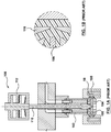
- An example of a side gate nozzle 100 with a valve gate is illustrated in Figures 1A and 1B .
- a nozzle body 102 is connected to the nozzle head 104, which has two gates.
- Each gate has a closure needle or valve pin 106 that is slidably received in the nozzle head 104 for opening and closing the gate to start and stop melt flow into the mold cavity 108, respectively.
- a rod 110 may be used to actuate the valve pins 106 and, as shown in FIG. 1A , may extend through the nozzle body 102. As illustrated in Figure 1A , the rod 110 may be driven by an actuator 112.
- a pressure equalizer for use with an edge gate or side gate nozzle is disclosed.
- a valve stem is provided in the nozzle to close off the connection between the injection unit and the nozzle tips. Pressure is thereby allowed to build up in the entire hot runner, which acts like an accumulator for the impending injection into the cavities. Once a threshold peak pressure is reached, the valve stem is opened and nearly instantly all of the nozzle tips and gates are pressurized to an equivalent peak pressure, which is sufficient to push the plugs out of the gates and allow melt to flow into the mold cavities.
- the threshold peak pressure is chosen to be sufficiently greater than a pressure of a gate most resistant to popping (e.g., the gate most resistant to pushing the plug out of the gate), which may thereby cause all of the gates in the housing to pop simultaneously and, thus, may cause the beginning of melt flow into the cavities to be more balanced.
- FIG. 2 illustrates an embodiment in which the pressure equalizer is disposed in a side gate nozzle 200.
- the side gate nozzle 200 includes a nozzle housing 202 having a melt bore or primary melt channel 204, which is fluidly connected to a secondary melt channel 206 in each nozzle tip 208.
- the nozzle tips 208 extend outwardly from a side of the nozzle housing 202.
- the nozzle tips 208 are attached (e.g., screwed) to the mold in fixed relation to respective mold cavities 210, and as the nozzle housing 202 expands with heat, the primary melt channel 204 aligns with the secondary melt channels 206.
- the nozzle tip may be directly attached to the nozzle body.
- the nozzle 200 may include two nozzle tips 208 and two corresponding secondary melt channels 206 in some embodiments, while in other embodiments, the nozzle 200 may include more or fewer nozzle tips and, thus, more or fewer secondary melt channels.
- the nozzle 200 may include 4, 8 or 12 nozzle tips and 4, 8, or 12 corresponding secondary melt channels.
- each of the secondary melt channels 206 passes melt to a mold cavity 210.
- the pressure equalizer allows the melt pressure of the nozzle 200 to build up to at least the threshold peak pressure (e.g., the pressure sufficient to overcome the most resistant gate) before beginning to fill each of the mold cavities.
- the pressure equalizer may include a valve stem 212 that is slidably received in the primary melt channel 204 and that reciprocally moves into open and closed positions to start and stop melt flow from the primary melt channel 204, respectively.
- Figure 2 illustrates an embodiment in which the pressure equalizer, i.e., the valve stem 212, is in a closed position, thus allowing the melt pressure to build up.
- the downstream end 214 of the valve stem 212 cooperates with a downstream end 216 of the primary melt channel 204 to close the primary melt channel 204 and block melt from flowing therefrom.
- the downstream end 214 of the valve stem 212 may fit tightly within the downstream end 216 of the primary melt channel 204 (e.g., there is no space between the downstream end 214 of the valve stem 212 and the downstream end 216 of the primary melt channel 204), thus preventing melt from flowing to the secondary melt channels 206.
- the shape and size of the downstream end 214 of the valve stem 212 may correspond to the shape and size of the downstream end 216 of the primary melt channel 204.
- the downstream end 214 of the valve stem 212 has a cylindrical shape that corresponds with a cylindrically-shaped downstream end 216 of the primary melt channel 204.
- other suitable shapes of the valve stem and of the primary melt channel may be used to close the primary melt channel as this aspect of the disclosure is not limited in this regard.
- the downstream end 314 of the valve stem 312 may be tapered and may cooperate with a tapered downstream end 316 of the primary melt channel 304.
- the downstream end of the valve stem may have a truncated conical shape that corresponds with the shape of the downstream end of the primary melt channel 204.
- valve stem is shown to cooperate with the downstream end of the primary melt channel, the valve stem also may cooperate with other suitable portions of the primary melt channel.
- the valve stem may cooperate with an upstream portion of primary melt channel, while in other embodiments the valve stem may cooperate with an end of the primary melt channel where the primary melt channel splits to fluidly communicate with each of the secondary melt channels.
- FIG 3 illustrates the nozzle of Figure 2 after the melt pressure has reached the threshold peak pressure.
- the valve stem 212 has been moved into a retracted (opened) position, thus allowing a flow of melt to travel from the primary melt channel 204 to the secondary melt channel 206, as indicated by arrows M.
- both of the secondary melt channels 206 will be nearly immediately and equally pressurized, which may allow each of the gates to pop and for melt to pass into the mold cavities 210.
- the valve stem 212 may be returned to the closed position shown in Figure 2 to rebuild melt pressure for another mold cycle.
- the nozzle 200 includes a heater 218, which may be located around the nozzle housing 202, although the heater may have other suitable positions for heating the melt.
- the heater 218 assists in building up the pressure of the melt by increasing the melt temperature.
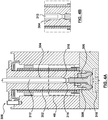
- Figures 4 and 5 illustrate embodiments in which the pressure equalizer is used in a multi-probe nozzle.
- the nozzle 300 includes a nozzle housing 302 with a primary melt channel 304 that is fluidly connected to secondary melt channels 306.
- the secondary melt channels 306 are located in nozzle tips 308, the secondary melt channel 306 passing melt to mold cavities 310.
- the cluster of nozzle tips 308 and corresponding secondary melt channels 306 are located at a downstream end of the nozzle housing 302.
- the nozzle tips 308 may be integrally formed with the nozzle housing 302 in some embodiments, while in other embodiments the nozzle tips 308 may be separate from the nozzle housing 302. In such embodiments, the nozzle tips 308 may be permanently attached to the nozzle housing 308 or maybe removably attachable.
- the pressure equalizer includes a valve stem 312 that is slidably disposed in the primary melt channel 304 and that reciprocally moves into open and closed positions to start and stop melt flow from the primary melt channel 304, respectively.
- Figure 4A illustrates a valve stem having a cylindrically-shaped downstream end that cooperates with a cylindrically-shaped downstream end of the primary melt channel 304.
- Figure 5A illustrates an embodiment in which the valve stem 312 has a tapered downstream end 314 that corresponds with a tapered downstream end 316 of the primary melt channel 304.
- Figures 4B and 5B illustrate embodiments in which the threshold peak pressure of the melt has been established and the valve stems 312 have been moved into a retracted (opened) position, thus allowing the melt to pass from the primary melt channel 304 to the secondary melt channels 306 to pop the gates for filling the mold cavities 310.
- the movement of the valve stems 212, 312 maybe driven by an actuator (not shown).
- an actuator may be used to drive valve stem 212, 312 movement.
- the actuator may include a piston (not shown) to drive valve stem movement, while in other embodiments the actuator (not shown) may include a motor (not shown), such as a servomotor, to drive valve stem movement.
- the nozzles 200, 300 are shown and described as having one nozzle housing with a plurality of clustered nozzle tips 208, 308, in other embodiments the nozzles 200, 300 may include multiple nozzle housings, each nozzle housing having the plurality of clustered nozzle tips extending therefrom. In such embodiments, the nozzles may be configured to simultaneously move all of the valve stems into the opened position once the threshold peak pressure is established in all of the primary melt channels. That is, one controller (not shown) may be configured to control all of the valve stems. In other embodiments, the nozzles may be configured such that each valve stem may be independently controllable.
- the corresponding first valve stem may be moved into an opened position to allow the melt to be passed from the first primary melt channel to the first secondary melt channel.
- a second valve stem in a second primary melt channel will be moved into the opened position only when the threshold peak pressure is reached in the second nozzle housing.
- the threshold peak pressures of the first and second nozzle housings may be reached at the same time in some embodiments, while in other embodiments the threshold peak pressures of the first and second nozzle housings may be reached at different times.
- the first and second valve stems may be moved at the same time, they also may be moved at different times.
- pressure equalizers have been shown and described as having a valve stem to open and close the primary melt channel to build up the melt pressure to at least the threshold peak pressure and thereafter equally pressurize all of the gates, a person having ordinary skill in the art should appreciate that other mechanisms or arrangements for opening and closing the primary melt channel (and building melt pressure) may be used.
- a rotary valve may be incorporated in or upstream of the nozzle melt channel.
Landscapes
- Engineering & Computer Science (AREA)
- Manufacturing & Machinery (AREA)
- Mechanical Engineering (AREA)
- Moulds For Moulding Plastics Or The Like (AREA)
- Injection Moulding Of Plastics Or The Like (AREA)
Claims (11)
- Buse à canaux chauffés (200, 300) pour faire passer une matière fondue dans une cavité de moule (210, 310), la buse à canaux chauffés comprenant :un boîtier de buse (202, 302) définissant un canal de fusion primaire (204, 304) ;une première pointe de buse (208, 308), la première pointe de buse (208, 308) ayant un premier canal de fusion secondaire (206, 306) en communication fluidique avec le canal de fusion primaire (204, 304) ;une deuxième pointe de buse (208, 308), la deuxième pointe de buse (208, 308) ayant un deuxième canal de fusion secondaire (206, 306) en communication fluidique avec le canal de fusion primaire (204, 304) ; caractérisée en ce queune soupape est disposée dans le canal de fusion primaire (204, 304) pour ouvrir et fermer sélectivement une extrémité aval (216, 316) du canal de fusion primaire (204, 304) pour commander un écoulement de matière fondue vers les premier et deuxième canaux de fusion secondaires (206, 306) .
- Buse à canaux chauffés (200, 300) selon la revendication 1, dans laquelle la buse à canaux chauffés est une buse à entrée latérale.
- Buse à canaux chauffés (200, 300) selon la revendication 1, dans laquelle la buse à canaux chauffés est une buse à sondes multiples.
- Buse à canaux chauffés (200, 300) selon l'une quelconque des revendications 1 à 3, dans laquelle la soupape est configurée pour s'ouvrir sélectivement lorsqu'une pression de la matière fondue atteint une pression maximale seuil.
- Buse à canaux chauffés (200, 300) selon l'une quelconque des revendications 1 à 4, dans laquelle la soupape comprend une tige de soupape (212, 312) disposée en coulissement dans le canal de fusion primaire (204, 304).
- Buse à canaux chauffés (200, 300) selon l'une quelconque des revendications 1 à 4, dans laquelle la soupape est positionnée dans une extrémité aval (216, 316) du canal de fusion primaire (204, 304).
- Buse à canaux chauffés (200, 300) selon la revendication 5, dans laquelle une extrémité aval (214, 314) de la tige de soupape (212, 312) coopère avec une extrémité aval (216, 316) du canal de fusion primaire (204, 304) .
- Procédé de passage de matière fondue dans des cavités de moule (210, 310), le procédé comprenant le fait :de fermer sélectivement une soupape disposée dans un canal de fusion primaire (204, 304) d'un boîtier de buse (202, 302) pour empêcher une matière fondue de s'écouler d'une extrémité aval (216, 316) du canal de fusion primaire (204, 304) ;de mettre sous pression la matière fondue dans le canal de fusion primaire (204, 304) jusqu'à ce que la pression de la matière fondue atteigne une pression maximale seuil ; etd'ouvrir sélectivement la soupape pour permettre à la matière fondue de s'écouler de l'extrémité aval (216, 316) du canal de fusion primaire (204, 304) vers un premier canal de fusion secondaire (206, 306) défini dans une première pointe de buse (208, 308) et un deuxième canal de fusion secondaire (206, 306) défini dans une deuxième pointe de buse (208, 308).
- Procédé selon la revendication 8, comprenant en outre le remplissage des première et deuxième cavités de moule (210, 310).
- Procédé selon la revendication 9, comprenant en outre la fermeture sélective de la soupape après le remplissage des première et deuxième cavités de moule (210, 310) .
- Procédé selon la revendication 10, dans lequel la fermeture sélective de la soupape comprend l'engagement d'une extrémité aval (214, 314) d'une tige de soupape (212, 312) avec l'extrémité aval (216, 316) du canal de fusion primaire (204, 304) pour bloquer un écoulement de matière fondue à partir de celui-ci.
Applications Claiming Priority (2)
| Application Number | Priority Date | Filing Date | Title |
|---|---|---|---|
| US201462080477P | 2014-11-17 | 2014-11-17 | |
| PCT/US2015/060792 WO2016081334A1 (fr) | 2014-11-17 | 2015-11-16 | Buse de canal chauffé comportant un égaliseur de pression de grille |
Publications (3)
| Publication Number | Publication Date |
|---|---|
| EP3242784A1 EP3242784A1 (fr) | 2017-11-15 |
| EP3242784A4 EP3242784A4 (fr) | 2018-10-10 |
| EP3242784B1 true EP3242784B1 (fr) | 2020-01-08 |
Family
ID=56014414
Family Applications (1)
| Application Number | Title | Priority Date | Filing Date |
|---|---|---|---|
| EP15860305.0A Active EP3242784B1 (fr) | 2014-11-17 | 2015-11-16 | Buse de canal chauffé comportant un égaliseur de pression de grille |
Country Status (4)
| Country | Link |
|---|---|
| US (1) | US10449706B2 (fr) |
| EP (1) | EP3242784B1 (fr) |
| CA (1) | CA2963822C (fr) |
| WO (1) | WO2016081334A1 (fr) |
Families Citing this family (1)
| Publication number | Priority date | Publication date | Assignee | Title |
|---|---|---|---|---|
| WO2025217713A1 (fr) * | 2024-04-19 | 2025-10-23 | Mold-Masters (2007) Limited | Appareil à canal chauffé à entrée latérale |
Family Cites Families (17)
| Publication number | Priority date | Publication date | Assignee | Title |
|---|---|---|---|---|
| US4073944A (en) | 1976-07-06 | 1978-02-14 | Cincinnati Milacron Inc. | Nozzle shut-off valve |
| KR920008771B1 (ko) | 1988-10-13 | 1992-10-09 | 세이끼 코포레이션 컴파니, 티미티드 | 사출성형 방법 및 장치 |
| JPH0822562B2 (ja) | 1990-05-24 | 1996-03-06 | 株式会社小松製作所 | 射出成形機のサイクル制御方法 |
| US5238393A (en) * | 1990-12-28 | 1993-08-24 | Sony Corporation | Multi-cavity injection molding apparatus for optical disk substrates |
| JP2928750B2 (ja) | 1995-09-27 | 1999-08-03 | 日精樹脂工業株式会社 | 射出成形における保圧方法 |
| DE19859472A1 (de) * | 1998-12-22 | 2000-11-30 | Krauss Maffei Kunststofftech | Verfahren zum Herstellen von mit Langfasern verstärkten Spritzgießteilen |
| DE10066145B4 (de) | 2000-04-14 | 2009-01-29 | Kraussmaffei Technologies Gmbh | Verfahren zum Betrieb einer Spritzgießmaschine mit kontinuierlich arbeitender Plastifiziereinheit |
| JP2002347084A (ja) * | 2001-05-23 | 2002-12-04 | Esuipi Kk | 射出成形用ホットランナ金型装置 |
| DE10231093C1 (de) | 2002-07-10 | 2003-10-30 | Otto Maenner Heiskanalsysteme | Spritzgießdüse für Kunststoff mit wenigstens zwei Austrittsöffnungen |
| US7306454B2 (en) | 2003-04-07 | 2007-12-11 | Mold-Masters Limited | Front-mountable injection molding nozzle |
| US7413131B2 (en) * | 2003-08-25 | 2008-08-19 | Husky Injection Molding Systems Ltd. | Hot runner system components of two materials and method of manufacture |
| US7125246B2 (en) | 2003-10-08 | 2006-10-24 | Mold Hotrunner Solutions Inc. | Hot runner for molding small plastic articles |
| WO2005113215A1 (fr) * | 2004-05-14 | 2005-12-01 | University Of Massachusetts | Procédés et dispositifs pour la régulation de la pression de fonte |
| DE102005017413B4 (de) | 2005-04-15 | 2008-06-26 | Otto Männer Innovation GmbH | Spritzgießdüse mit zwei Austrittsöffnungen |
| US7658606B2 (en) * | 2006-12-22 | 2010-02-09 | Mold-Masters (2007) Limited | Edge gated injection molding apparatus |
| ATE544573T1 (de) | 2006-12-29 | 2012-02-15 | Mold Masters 2007 Ltd | SPRITZGIEßVORRICHTUNG MIT SEITLICHER ANGUSSÖFFNUNG |
| DE102007052597A1 (de) * | 2007-11-03 | 2009-05-07 | Mht Mold & Hotrunner Technology Ag | Angußadapter sowie Angußsystem für einen Angußadapter |
-
2015
- 2015-11-16 CA CA2963822A patent/CA2963822C/fr active Active
- 2015-11-16 US US15/525,098 patent/US10449706B2/en active Active
- 2015-11-16 WO PCT/US2015/060792 patent/WO2016081334A1/fr not_active Ceased
- 2015-11-16 EP EP15860305.0A patent/EP3242784B1/fr active Active
Non-Patent Citations (1)
| Title |
|---|
| None * |
Also Published As
| Publication number | Publication date |
|---|---|
| US10449706B2 (en) | 2019-10-22 |
| WO2016081334A1 (fr) | 2016-05-26 |
| CA2963822C (fr) | 2018-11-20 |
| CA2963822A1 (fr) | 2016-05-26 |
| EP3242784A1 (fr) | 2017-11-15 |
| EP3242784A4 (fr) | 2018-10-10 |
| US20180015653A1 (en) | 2018-01-18 |
Similar Documents
| Publication | Publication Date | Title |
|---|---|---|
| EP3062985B1 (fr) | Commande à vitesse réduite basée sur des conditions de système détectées | |
| EP1447200B1 (fr) | Buse à obturation avec réglage de débit indépendant pour une presse à injecter | |
| TWI658917B (zh) | 改造射出成型機之方法 | |
| US7658606B2 (en) | Edge gated injection molding apparatus | |
| CA2307945C (fr) | Appareil et methode de commande de coulure | |
| KR101948963B1 (ko) | 플라스틱 재료의 인젝션 몰딩 방법 | |
| EP2864098B1 (fr) | Pile de moules ayant une vanne d'air et procédé de moulage | |
| US9776349B2 (en) | System for controlling the closing speed of valve gated nozzles | |
| US7192270B2 (en) | Tight pitch nozzle with individual valve gate control | |
| EP1941984B1 (fr) | Appareil de moulage par injection avec entrées d'injection latérales | |
| US7210922B1 (en) | Valve pin operating mechanism | |
| JP5101158B2 (ja) | 多点ゲート射出成形機におけるノズルゲート開閉タイミング調整機構及び多点ゲート射出成形方法 | |
| CA2963822C (fr) | Buse de canal chauffe comportant un egaliseur de pression de grille | |
| WO2015079002A1 (fr) | Appareil d'injection à canaux chauffés et procédé d'injection latérale avec goupilles de soupape indépendantes | |
| WO2013044375A1 (fr) | Système d'outil de moulage comportant un ensemble de commande de réduction de pression de matière fondue destiné à réduire sélectivement la pression d'une matière fondue dans une zone de fusion | |
| KR20110101174A (ko) | 몰딩 시스템의 작동 방법 | |
| US20060204609A1 (en) | Hot-channel distribution block for an injection molding system | |
| ITTO20070338A1 (it) | Stampo per lo stampaggio ad iniezione di manufatti in materiale plastico e relativo metodo di funzionamento |
Legal Events
| Date | Code | Title | Description |
|---|---|---|---|
| STAA | Information on the status of an ep patent application or granted ep patent |
Free format text: STATUS: THE INTERNATIONAL PUBLICATION HAS BEEN MADE |
|
| PUAI | Public reference made under article 153(3) epc to a published international application that has entered the european phase |
Free format text: ORIGINAL CODE: 0009012 |
|
| STAA | Information on the status of an ep patent application or granted ep patent |
Free format text: STATUS: REQUEST FOR EXAMINATION WAS MADE |
|
| 17P | Request for examination filed |
Effective date: 20171004 |
|
| AK | Designated contracting states |
Kind code of ref document: A1 Designated state(s): AL AT BE BG CH CY CZ DE DK EE ES FI FR GB GR HR HU IE IS IT LI LT LU LV MC MK MT NL NO PL PT RO RS SE SI SK SM TR |
|
| AX | Request for extension of the european patent |
Extension state: BA ME |
|
| DAV | Request for validation of the european patent (deleted) | ||
| DAX | Request for extension of the european patent (deleted) | ||
| REG | Reference to a national code |
Ref country code: DE Ref legal event code: R079 Ref document number: 602015045380 Country of ref document: DE Free format text: PREVIOUS MAIN CLASS: B29C0045230000 Ipc: B29C0045270000 |
|
| A4 | Supplementary search report drawn up and despatched |
Effective date: 20180910 |
|
| RIC1 | Information provided on ipc code assigned before grant |
Ipc: B29C 45/27 20060101AFI20180904BHEP Ipc: B29C 45/28 20060101ALI20180904BHEP |
|
| GRAP | Despatch of communication of intention to grant a patent |
Free format text: ORIGINAL CODE: EPIDOSNIGR1 |
|
| STAA | Information on the status of an ep patent application or granted ep patent |
Free format text: STATUS: GRANT OF PATENT IS INTENDED |
|
| INTG | Intention to grant announced |
Effective date: 20190729 |
|
| GRAS | Grant fee paid |
Free format text: ORIGINAL CODE: EPIDOSNIGR3 |
|
| GRAA | (expected) grant |
Free format text: ORIGINAL CODE: 0009210 |
|
| STAA | Information on the status of an ep patent application or granted ep patent |
Free format text: STATUS: THE PATENT HAS BEEN GRANTED |
|
| AK | Designated contracting states |
Kind code of ref document: B1 Designated state(s): AL AT BE BG CH CY CZ DE DK EE ES FI FR GB GR HR HU IE IS IT LI LT LU LV MC MK MT NL NO PL PT RO RS SE SI SK SM TR |
|
| RAP1 | Party data changed (applicant data changed or rights of an application transferred) |
Owner name: HUSKY INJECTION MOLDING SYSTEMS LTD. |
|
| REG | Reference to a national code |
Ref country code: GB Ref legal event code: FG4D |
|
| REG | Reference to a national code |
Ref country code: CH Ref legal event code: EP |
|
| REG | Reference to a national code |
Ref country code: DE Ref legal event code: R096 Ref document number: 602015045380 Country of ref document: DE |
|
| REG | Reference to a national code |
Ref country code: IE Ref legal event code: FG4D |
|
| REG | Reference to a national code |
Ref country code: AT Ref legal event code: REF Ref document number: 1222148 Country of ref document: AT Kind code of ref document: T Effective date: 20200215 |
|
| REG | Reference to a national code |
Ref country code: NL Ref legal event code: MP Effective date: 20200108 |
|
| REG | Reference to a national code |
Ref country code: LT Ref legal event code: MG4D |
|
| PG25 | Lapsed in a contracting state [announced via postgrant information from national office to epo] |
Ref country code: NL Free format text: LAPSE BECAUSE OF FAILURE TO SUBMIT A TRANSLATION OF THE DESCRIPTION OR TO PAY THE FEE WITHIN THE PRESCRIBED TIME-LIMIT Effective date: 20200108 Ref country code: RS Free format text: LAPSE BECAUSE OF FAILURE TO SUBMIT A TRANSLATION OF THE DESCRIPTION OR TO PAY THE FEE WITHIN THE PRESCRIBED TIME-LIMIT Effective date: 20200108 Ref country code: LT Free format text: LAPSE BECAUSE OF FAILURE TO SUBMIT A TRANSLATION OF THE DESCRIPTION OR TO PAY THE FEE WITHIN THE PRESCRIBED TIME-LIMIT Effective date: 20200108 Ref country code: PT Free format text: LAPSE BECAUSE OF FAILURE TO SUBMIT A TRANSLATION OF THE DESCRIPTION OR TO PAY THE FEE WITHIN THE PRESCRIBED TIME-LIMIT Effective date: 20200531 Ref country code: NO Free format text: LAPSE BECAUSE OF FAILURE TO SUBMIT A TRANSLATION OF THE DESCRIPTION OR TO PAY THE FEE WITHIN THE PRESCRIBED TIME-LIMIT Effective date: 20200408 Ref country code: FI Free format text: LAPSE BECAUSE OF FAILURE TO SUBMIT A TRANSLATION OF THE DESCRIPTION OR TO PAY THE FEE WITHIN THE PRESCRIBED TIME-LIMIT Effective date: 20200108 |
|
| PG25 | Lapsed in a contracting state [announced via postgrant information from national office to epo] |
Ref country code: SE Free format text: LAPSE BECAUSE OF FAILURE TO SUBMIT A TRANSLATION OF THE DESCRIPTION OR TO PAY THE FEE WITHIN THE PRESCRIBED TIME-LIMIT Effective date: 20200108 Ref country code: LV Free format text: LAPSE BECAUSE OF FAILURE TO SUBMIT A TRANSLATION OF THE DESCRIPTION OR TO PAY THE FEE WITHIN THE PRESCRIBED TIME-LIMIT Effective date: 20200108 Ref country code: HR Free format text: LAPSE BECAUSE OF FAILURE TO SUBMIT A TRANSLATION OF THE DESCRIPTION OR TO PAY THE FEE WITHIN THE PRESCRIBED TIME-LIMIT Effective date: 20200108 Ref country code: IS Free format text: LAPSE BECAUSE OF FAILURE TO SUBMIT A TRANSLATION OF THE DESCRIPTION OR TO PAY THE FEE WITHIN THE PRESCRIBED TIME-LIMIT Effective date: 20200508 Ref country code: BG Free format text: LAPSE BECAUSE OF FAILURE TO SUBMIT A TRANSLATION OF THE DESCRIPTION OR TO PAY THE FEE WITHIN THE PRESCRIBED TIME-LIMIT Effective date: 20200408 Ref country code: GR Free format text: LAPSE BECAUSE OF FAILURE TO SUBMIT A TRANSLATION OF THE DESCRIPTION OR TO PAY THE FEE WITHIN THE PRESCRIBED TIME-LIMIT Effective date: 20200409 |
|
| REG | Reference to a national code |
Ref country code: DE Ref legal event code: R097 Ref document number: 602015045380 Country of ref document: DE |
|
| PG25 | Lapsed in a contracting state [announced via postgrant information from national office to epo] |
Ref country code: SK Free format text: LAPSE BECAUSE OF FAILURE TO SUBMIT A TRANSLATION OF THE DESCRIPTION OR TO PAY THE FEE WITHIN THE PRESCRIBED TIME-LIMIT Effective date: 20200108 Ref country code: RO Free format text: LAPSE BECAUSE OF FAILURE TO SUBMIT A TRANSLATION OF THE DESCRIPTION OR TO PAY THE FEE WITHIN THE PRESCRIBED TIME-LIMIT Effective date: 20200108 Ref country code: CZ Free format text: LAPSE BECAUSE OF FAILURE TO SUBMIT A TRANSLATION OF THE DESCRIPTION OR TO PAY THE FEE WITHIN THE PRESCRIBED TIME-LIMIT Effective date: 20200108 Ref country code: ES Free format text: LAPSE BECAUSE OF FAILURE TO SUBMIT A TRANSLATION OF THE DESCRIPTION OR TO PAY THE FEE WITHIN THE PRESCRIBED TIME-LIMIT Effective date: 20200108 Ref country code: DK Free format text: LAPSE BECAUSE OF FAILURE TO SUBMIT A TRANSLATION OF THE DESCRIPTION OR TO PAY THE FEE WITHIN THE PRESCRIBED TIME-LIMIT Effective date: 20200108 Ref country code: SM Free format text: LAPSE BECAUSE OF FAILURE TO SUBMIT A TRANSLATION OF THE DESCRIPTION OR TO PAY THE FEE WITHIN THE PRESCRIBED TIME-LIMIT Effective date: 20200108 Ref country code: EE Free format text: LAPSE BECAUSE OF FAILURE TO SUBMIT A TRANSLATION OF THE DESCRIPTION OR TO PAY THE FEE WITHIN THE PRESCRIBED TIME-LIMIT Effective date: 20200108 |
|
| PLBE | No opposition filed within time limit |
Free format text: ORIGINAL CODE: 0009261 |
|
| STAA | Information on the status of an ep patent application or granted ep patent |
Free format text: STATUS: NO OPPOSITION FILED WITHIN TIME LIMIT |
|
| REG | Reference to a national code |
Ref country code: AT Ref legal event code: MK05 Ref document number: 1222148 Country of ref document: AT Kind code of ref document: T Effective date: 20200108 |
|
| 26N | No opposition filed |
Effective date: 20201009 |
|
| PG25 | Lapsed in a contracting state [announced via postgrant information from national office to epo] |
Ref country code: AT Free format text: LAPSE BECAUSE OF FAILURE TO SUBMIT A TRANSLATION OF THE DESCRIPTION OR TO PAY THE FEE WITHIN THE PRESCRIBED TIME-LIMIT Effective date: 20200108 |
|
| PG25 | Lapsed in a contracting state [announced via postgrant information from national office to epo] |
Ref country code: SI Free format text: LAPSE BECAUSE OF FAILURE TO SUBMIT A TRANSLATION OF THE DESCRIPTION OR TO PAY THE FEE WITHIN THE PRESCRIBED TIME-LIMIT Effective date: 20200108 Ref country code: PL Free format text: LAPSE BECAUSE OF FAILURE TO SUBMIT A TRANSLATION OF THE DESCRIPTION OR TO PAY THE FEE WITHIN THE PRESCRIBED TIME-LIMIT Effective date: 20200108 |
|
| PG25 | Lapsed in a contracting state [announced via postgrant information from national office to epo] |
Ref country code: MC Free format text: LAPSE BECAUSE OF FAILURE TO SUBMIT A TRANSLATION OF THE DESCRIPTION OR TO PAY THE FEE WITHIN THE PRESCRIBED TIME-LIMIT Effective date: 20200108 |
|
| REG | Reference to a national code |
Ref country code: BE Ref legal event code: MM Effective date: 20201130 |
|
| PG25 | Lapsed in a contracting state [announced via postgrant information from national office to epo] |
Ref country code: IE Free format text: LAPSE BECAUSE OF NON-PAYMENT OF DUE FEES Effective date: 20201116 |
|
| PG25 | Lapsed in a contracting state [announced via postgrant information from national office to epo] |
Ref country code: TR Free format text: LAPSE BECAUSE OF FAILURE TO SUBMIT A TRANSLATION OF THE DESCRIPTION OR TO PAY THE FEE WITHIN THE PRESCRIBED TIME-LIMIT Effective date: 20200108 Ref country code: MT Free format text: LAPSE BECAUSE OF FAILURE TO SUBMIT A TRANSLATION OF THE DESCRIPTION OR TO PAY THE FEE WITHIN THE PRESCRIBED TIME-LIMIT Effective date: 20200108 Ref country code: CY Free format text: LAPSE BECAUSE OF FAILURE TO SUBMIT A TRANSLATION OF THE DESCRIPTION OR TO PAY THE FEE WITHIN THE PRESCRIBED TIME-LIMIT Effective date: 20200108 |
|
| PG25 | Lapsed in a contracting state [announced via postgrant information from national office to epo] |
Ref country code: MK Free format text: LAPSE BECAUSE OF FAILURE TO SUBMIT A TRANSLATION OF THE DESCRIPTION OR TO PAY THE FEE WITHIN THE PRESCRIBED TIME-LIMIT Effective date: 20200108 Ref country code: AL Free format text: LAPSE BECAUSE OF FAILURE TO SUBMIT A TRANSLATION OF THE DESCRIPTION OR TO PAY THE FEE WITHIN THE PRESCRIBED TIME-LIMIT Effective date: 20200108 |
|
| PG25 | Lapsed in a contracting state [announced via postgrant information from national office to epo] |
Ref country code: BE Free format text: LAPSE BECAUSE OF NON-PAYMENT OF DUE FEES Effective date: 20201130 |
|
| P01 | Opt-out of the competence of the unified patent court (upc) registered |
Effective date: 20230516 |
|
| PGFP | Annual fee paid to national office [announced via postgrant information from national office to epo] |
Ref country code: LU Payment date: 20251010 Year of fee payment: 11 |
|
| REG | Reference to a national code |
Ref country code: CH Ref legal event code: U11 Free format text: ST27 STATUS EVENT CODE: U-0-0-U10-U11 (AS PROVIDED BY THE NATIONAL OFFICE) Effective date: 20251201 |
|
| PGFP | Annual fee paid to national office [announced via postgrant information from national office to epo] |
Ref country code: DE Payment date: 20250912 Year of fee payment: 11 |
|
| PGFP | Annual fee paid to national office [announced via postgrant information from national office to epo] |
Ref country code: GB Payment date: 20251010 Year of fee payment: 11 |
|
| PGFP | Annual fee paid to national office [announced via postgrant information from national office to epo] |
Ref country code: IT Payment date: 20251103 Year of fee payment: 11 |
|
| PGFP | Annual fee paid to national office [announced via postgrant information from national office to epo] |
Ref country code: FR Payment date: 20251010 Year of fee payment: 11 |
|
| PGFP | Annual fee paid to national office [announced via postgrant information from national office to epo] |
Ref country code: CH Payment date: 20251201 Year of fee payment: 11 |