EP3242802B1 - Mobiles medizinisches gerät mit mindestens einem motorisch angetriebenen rad - Google Patents
Mobiles medizinisches gerät mit mindestens einem motorisch angetriebenen rad Download PDFInfo
- Publication number
- EP3242802B1 EP3242802B1 EP16714334.6A EP16714334A EP3242802B1 EP 3242802 B1 EP3242802 B1 EP 3242802B1 EP 16714334 A EP16714334 A EP 16714334A EP 3242802 B1 EP3242802 B1 EP 3242802B1
- Authority
- EP
- European Patent Office
- Prior art keywords
- motor
- driven wheel
- medical device
- hub
- mobile medical
- Prior art date
- Legal status (The legal status is an assumption and is not a legal conclusion. Google has not performed a legal analysis and makes no representation as to the accuracy of the status listed.)
- Not-in-force
Links
Images



Classifications
-
- B—PERFORMING OPERATIONS; TRANSPORTING
- B60—VEHICLES IN GENERAL
- B60B—VEHICLE WHEELS; CASTORS; AXLES FOR WHEELS OR CASTORS; INCREASING WHEEL ADHESION
- B60B3/00—Disc wheels, i.e. wheels with load-supporting disc body
- B60B3/14—Attaching disc body to hub ; Wheel adapters
-
- A—HUMAN NECESSITIES
- A61—MEDICAL OR VETERINARY SCIENCE; HYGIENE
- A61G—TRANSPORT, PERSONAL CONVEYANCES, OR ACCOMMODATION SPECIALLY ADAPTED FOR PATIENTS OR DISABLED PERSONS; OPERATING TABLES OR CHAIRS; CHAIRS FOR DENTISTRY; FUNERAL DEVICES
- A61G13/00—Operating tables; Auxiliary appliances therefor
- A61G13/10—Parts, details or accessories
- A61G13/104—Adaptations for table mobility, e.g. arrangement of wheels
-
- B—PERFORMING OPERATIONS; TRANSPORTING
- B60—VEHICLES IN GENERAL
- B60B—VEHICLE WHEELS; CASTORS; AXLES FOR WHEELS OR CASTORS; INCREASING WHEEL ADHESION
- B60B19/00—Wheels not otherwise provided for or having characteristics specified in one of the subgroups of this group
- B60B19/003—Multidirectional wheels
-
- B—PERFORMING OPERATIONS; TRANSPORTING
- B60—VEHICLES IN GENERAL
- B60B—VEHICLE WHEELS; CASTORS; AXLES FOR WHEELS OR CASTORS; INCREASING WHEEL ADHESION
- B60B3/00—Disc wheels, i.e. wheels with load-supporting disc body
- B60B3/14—Attaching disc body to hub ; Wheel adapters
- B60B3/147—Attaching disc body to hub ; Wheel adapters using wheel adapters
-
- B—PERFORMING OPERATIONS; TRANSPORTING
- B60—VEHICLES IN GENERAL
- B60B—VEHICLE WHEELS; CASTORS; AXLES FOR WHEELS OR CASTORS; INCREASING WHEEL ADHESION
- B60B3/00—Disc wheels, i.e. wheels with load-supporting disc body
- B60B3/14—Attaching disc body to hub ; Wheel adapters
- B60B3/16—Attaching disc body to hub ; Wheel adapters by bolts or the like
- B60B3/165—Attaching disc body to hub ; Wheel adapters by bolts or the like with locking devices for the fixing means, e.g. screw or nut covers
-
- B—PERFORMING OPERATIONS; TRANSPORTING
- B60—VEHICLES IN GENERAL
- B60K—ARRANGEMENT OR MOUNTING OF PROPULSION UNITS OR OF TRANSMISSIONS IN VEHICLES; ARRANGEMENT OR MOUNTING OF PLURAL DIVERSE PRIME-MOVERS IN VEHICLES; AUXILIARY DRIVES FOR VEHICLES; INSTRUMENTATION OR DASHBOARDS FOR VEHICLES; ARRANGEMENTS IN CONNECTION WITH COOLING, AIR INTAKE, GAS EXHAUST OR FUEL SUPPLY OF PROPULSION UNITS IN VEHICLES
- B60K7/00—Disposition of motor in, or adjacent to, traction wheel
- B60K7/0007—Disposition of motor in, or adjacent to, traction wheel the motor being electric
-
- A—HUMAN NECESSITIES
- A61—MEDICAL OR VETERINARY SCIENCE; HYGIENE
- A61B—DIAGNOSIS; SURGERY; IDENTIFICATION
- A61B6/00—Apparatus or devices for radiation diagnosis; Apparatus or devices for radiation diagnosis combined with radiation therapy equipment
- A61B6/44—Constructional features of apparatus for radiation diagnosis
- A61B6/4405—Constructional features of apparatus for radiation diagnosis the apparatus being movable or portable, e.g. handheld or mounted on a trolley
-
- A—HUMAN NECESSITIES
- A61—MEDICAL OR VETERINARY SCIENCE; HYGIENE
- A61B—DIAGNOSIS; SURGERY; IDENTIFICATION
- A61B6/00—Apparatus or devices for radiation diagnosis; Apparatus or devices for radiation diagnosis combined with radiation therapy equipment
- A61B6/44—Constructional features of apparatus for radiation diagnosis
- A61B6/4429—Constructional features of apparatus for radiation diagnosis related to the mounting of source units and detector units
- A61B6/4435—Constructional features of apparatus for radiation diagnosis related to the mounting of source units and detector units the source unit and the detector unit being coupled by a rigid structure
- A61B6/4441—Constructional features of apparatus for radiation diagnosis related to the mounting of source units and detector units the source unit and the detector unit being coupled by a rigid structure the rigid structure being a C-arm or U-arm
-
- A—HUMAN NECESSITIES
- A61—MEDICAL OR VETERINARY SCIENCE; HYGIENE
- A61G—TRANSPORT, PERSONAL CONVEYANCES, OR ACCOMMODATION SPECIALLY ADAPTED FOR PATIENTS OR DISABLED PERSONS; OPERATING TABLES OR CHAIRS; CHAIRS FOR DENTISTRY; FUNERAL DEVICES
- A61G7/00—Beds specially adapted for nursing; Devices for lifting patients or disabled persons
- A61G7/002—Beds specially adapted for nursing; Devices for lifting patients or disabled persons having adjustable mattress frame
- A61G7/018—Control or drive mechanisms
-
- A—HUMAN NECESSITIES
- A61—MEDICAL OR VETERINARY SCIENCE; HYGIENE
- A61G—TRANSPORT, PERSONAL CONVEYANCES, OR ACCOMMODATION SPECIALLY ADAPTED FOR PATIENTS OR DISABLED PERSONS; OPERATING TABLES OR CHAIRS; CHAIRS FOR DENTISTRY; FUNERAL DEVICES
- A61G7/00—Beds specially adapted for nursing; Devices for lifting patients or disabled persons
- A61G7/05—Parts, details or accessories of beds
-
- A—HUMAN NECESSITIES
- A61—MEDICAL OR VETERINARY SCIENCE; HYGIENE
- A61G—TRANSPORT, PERSONAL CONVEYANCES, OR ACCOMMODATION SPECIALLY ADAPTED FOR PATIENTS OR DISABLED PERSONS; OPERATING TABLES OR CHAIRS; CHAIRS FOR DENTISTRY; FUNERAL DEVICES
- A61G7/00—Beds specially adapted for nursing; Devices for lifting patients or disabled persons
- A61G7/08—Apparatus for transporting beds
-
- B—PERFORMING OPERATIONS; TRANSPORTING
- B60—VEHICLES IN GENERAL
- B60B—VEHICLE WHEELS; CASTORS; AXLES FOR WHEELS OR CASTORS; INCREASING WHEEL ADHESION
- B60B2200/00—Type of product being used or applied
- B60B2200/20—Furniture or medical appliances
- B60B2200/26—Medical appliances
-
- B—PERFORMING OPERATIONS; TRANSPORTING
- B60—VEHICLES IN GENERAL
- B60B—VEHICLE WHEELS; CASTORS; AXLES FOR WHEELS OR CASTORS; INCREASING WHEEL ADHESION
- B60B2900/00—Purpose of invention
- B60B2900/20—Avoidance of
- B60B2900/211—Soiling
-
- B—PERFORMING OPERATIONS; TRANSPORTING
- B60—VEHICLES IN GENERAL
- B60B—VEHICLE WHEELS; CASTORS; AXLES FOR WHEELS OR CASTORS; INCREASING WHEEL ADHESION
- B60B2900/00—Purpose of invention
- B60B2900/50—Improvement of
- B60B2900/541—Servicing
-
- B—PERFORMING OPERATIONS; TRANSPORTING
- B60—VEHICLES IN GENERAL
- B60B—VEHICLE WHEELS; CASTORS; AXLES FOR WHEELS OR CASTORS; INCREASING WHEEL ADHESION
- B60B3/00—Disc wheels, i.e. wheels with load-supporting disc body
- B60B3/14—Attaching disc body to hub ; Wheel adapters
- B60B3/18—Attaching disc body to hub ; Wheel adapters by circlips or the like
-
- B—PERFORMING OPERATIONS; TRANSPORTING
- B60—VEHICLES IN GENERAL
- B60B—VEHICLE WHEELS; CASTORS; AXLES FOR WHEELS OR CASTORS; INCREASING WHEEL ADHESION
- B60B37/00—Wheel-axle combinations, e.g. wheel sets
- B60B37/10—Wheel-axle combinations, e.g. wheel sets the wheels being individually rotatable around the axles
-
- B—PERFORMING OPERATIONS; TRANSPORTING
- B60—VEHICLES IN GENERAL
- B60B—VEHICLE WHEELS; CASTORS; AXLES FOR WHEELS OR CASTORS; INCREASING WHEEL ADHESION
- B60B7/00—Wheel cover discs, rings, or the like, for ornamenting, protecting, venting, or obscuring, wholly or in part, the wheel body, rim, hub, or tyre sidewall, e.g. wheel cover discs, wheel cover discs with cooling fins
-
- B—PERFORMING OPERATIONS; TRANSPORTING
- B60—VEHICLES IN GENERAL
- B60K—ARRANGEMENT OR MOUNTING OF PROPULSION UNITS OR OF TRANSMISSIONS IN VEHICLES; ARRANGEMENT OR MOUNTING OF PLURAL DIVERSE PRIME-MOVERS IN VEHICLES; AUXILIARY DRIVES FOR VEHICLES; INSTRUMENTATION OR DASHBOARDS FOR VEHICLES; ARRANGEMENTS IN CONNECTION WITH COOLING, AIR INTAKE, GAS EXHAUST OR FUEL SUPPLY OF PROPULSION UNITS IN VEHICLES
- B60K7/00—Disposition of motor in, or adjacent to, traction wheel
- B60K2007/0038—Disposition of motor in, or adjacent to, traction wheel the motor moving together with the wheel axle
-
- B—PERFORMING OPERATIONS; TRANSPORTING
- B60—VEHICLES IN GENERAL
- B60K—ARRANGEMENT OR MOUNTING OF PROPULSION UNITS OR OF TRANSMISSIONS IN VEHICLES; ARRANGEMENT OR MOUNTING OF PLURAL DIVERSE PRIME-MOVERS IN VEHICLES; AUXILIARY DRIVES FOR VEHICLES; INSTRUMENTATION OR DASHBOARDS FOR VEHICLES; ARRANGEMENTS IN CONNECTION WITH COOLING, AIR INTAKE, GAS EXHAUST OR FUEL SUPPLY OF PROPULSION UNITS IN VEHICLES
- B60K7/00—Disposition of motor in, or adjacent to, traction wheel
- B60K2007/0092—Disposition of motor in, or adjacent to, traction wheel the motor axle being coaxial to the wheel axle
Definitions
- Mobile medical device with at least one motor-driven wheel
- the invention relates to a mobile medical device which can be moved on a floor surface with the aid of motor-driven wheels.
- the medical device is, for example, a patient couch or a C-arm X-ray device.
- Mobile medical devices usually have a chassis with manually or motor-driven wheels and are used in medical areas, especially in operating theaters.
- the floor surface can be contaminated, for example, by body fluids, rinsing fluids or consumables.
- the Mecanum wheel is a wheel that allows a vehicle equipped with it to perform omnidirectional driving maneuvers without having to be equipped with mechanical steering.
- Several rotatably mounted barrel-shaped rollers are attached to the circumference of the wheel, usually at an angle of 45 degrees to the axis of the entire wheel. Only these roles make contact with the ground surface.
- the rollers do not have their own direct drive and can rotate freely around their inclined bearing axis.
- the entire Mecanum wheel is driven by a drive motor with changeable direction of rotation and variable Speed driven. In order to implement the omnidirectional driving maneuver, the speed and the direction of rotation of each wheel are controlled individually.
- Motor-driven wheels and omnidirectional wheels such as the Mecanum wheels, are difficult to clean because of their structure or their mounting. It is common practice to wipe the floor and the equipment in an operating theater and subject them to particularly thorough cleaning and disinfection at specific intervals. A thorough cleaning of the wheels is difficult.
- a quick release hub and wheel assembly is disclosed.
- the assembly includes inner and outer sleeves arranged around a rotatable locking ring.
- the locking ring can be preloaded into a locked position and temporarily brought into an unlocked position.
- US 8 549 705 B1 describes a ring gear set which comprises a hollow rotary wheel, a gear wheel, a limiting sleeve and a limiting and fastening ring.
- the wheel mount has a mounting arm on which a wheel fork is provided. The hollow rotary wheel is pulled onto the wheel fork.
- a drive wheel comprising a wheel hub can be attached to a mobile medical device in the form of a wheelchair, in particular to its wheelchair frame, via a quick release axle.
- a mechanism comprising locking balls is provided which can be actuated via an actuating element in the form of a manually moved bracket and adjusted between a locking position and a release position. In the locked position of the bracket, there is a secure connection between the drive wheel and the vehicle frame. A drive of the drive wheel by means of an electric motor is prevented if the connection is not secure.
- the object of the invention is to provide a mobile medical device with motor-driven wheels that can be used in a contaminated environment.
- the set object is achieved with the mobile medical device with at least one motor-driven wheel of the independent claim.
- the motor-driven wheel is designed so that it can be removed from a rotatable hub of the mobile medical device and re-attached with bare hands, that is, by hand and without aids such as tools.
- the invention claims a mobile medical device with at least one motor-driven wheel with which the mobile medical device can be moved.
- the motor-driven wheel is arranged on a hub belonging to the motor-driven wheel and can be reversibly removed from the hub by hand and without tools and can be reversibly attached to the hub.
- This also includes motor driven wheel a locking device with which the motor-driven wheel can be releasably fixedly connected to the hub and released from the hub.
- the locking device has a handle element which can be folded out and which is arranged on the end face of the motor-driven wheel facing away from the medical device.
- the invention offers the advantage that, in order to clean the motor-driven wheel, it can be very easily removed from the medical device and cleaned, for example, in a suitable washing and disinfection device.
- the motor-driven wheel is designed as an omnidirectional wheel.
- the hub is rotatably mounted on an axis of the mobile medical device.
- grooves can be arranged on the circumference of the hub and corresponding guide elements of the locking device can engage in these grooves, the locking device being designed to be rotatable.
- the rotatable locking device has grooves and corresponding guide elements engaging in the grooves are arranged on the circumference of the hub.
- the locking device and the hub can be designed in such a way that the grip element can only be folded in in a locked position of the motor-driven wheel.
- the medical device has a protective plate-like cover element that can be folded over the motor-driven wheel.
- the cover element is can only be folded in a locked position of the motor-driven wheel.
- the mobile medical device has a lifting device which can lift the motor-driven wheel from a floor surface.
- an electric motor is arranged in the axle, which drives the motor-driven wheel.
- the mobile medical device can also have at least one non-motor-driven further wheel with which the mobile medical device can be moved when the motor-driven wheel is raised.
- the mobile medical device has at least four omnidirectional wheels, these being designed as mecanum wheels.
- the hub is frustoconical and the motor-driven wheel has a corresponding frustoconical recess.
- At least one anti-rotation element is arranged on the circumference of the hub, which element holds the motor-driven wheel on the hub so that it cannot rotate.
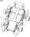
- Fig. 1 shows a mobile medical device 1 with at least one motor-driven wheel 2.
- the mobile medical device 1 has four wheels 2, each of which is motor-driven by its own electric motor 3.
- a protective plate-like, foldable cover element 4 is arranged over the motor-driven wheel 2, which can be seen in the open position. In the closed position, that is to say in the folded-down position, the cover element 4 can act to repel dirt and additionally act as a cable deflector.
- Fig. 1 also shows the mobile medical device 1 with a lifting device 13 of the motor-driven wheels 2 and with four further wheels 12 that are not motor-driven.
- each motor-driven wheel 2 has a lifting device 13. This means that each motor-driven wheel 2 can be lifted individually from a floor surface. When a wheel is changed, the mobile medical device 1 is supported on the remaining motor-driven wheels 2 that are not raised on the ground. In this embodiment, not shown, no additional wheels 12 or, for example, supports are required.
- all motor-driven wheels 2 can be lifted from the ground surface by the lifting devices 13 at the same time.
- the mobile medical device 1 has a further, second set of wheels consisting of at least two non-motor-driven wheels 12 or supports on which the mobile medical device 1 can be supported on the floor surface.
- the raised motor-driven wheels 2 are consequently free and can be removed.
- the lifting device 13 it is designed such that the motor-driven wheels 2 to be replaced remain at an unchanged height relative to a chassis of the mobile medical device 1.
- a chassis to mean the entirety of all parts of a mobile device which are used to connect the structure of the mobile device to the roadway via the wheels 2, which in this case are motor-driven. The entire chassis can then be lifted from the ground surface with the aid of additional wheels 12 or supports.
- the mobile medical device 1 preferably has a second set of wheels, i.e. at least three further, non-motor-driven wheels 12, since these can ensure that the mobile medical device 1 is nonetheless in the event of a failure of the motor drive by the electric motors 3 of the motor-driven wheels 2 can be moved and these are therefore safety-relevant.
- the mobile medical device 1 has four motor-driven wheels 2 in the form of omnidirectional wheels 15, for example Mecanum wheels.
- omnidirectional wheels for example Mecanum wheels.
- Mecanum wheels the direction of rotation and the speed of each individual wheel are controlled separately. This offers the advantage of optimal maneuverability, especially in tight spaces, as is often the case in operating theaters.
- Fig. 2 shows the motor-driven wheel 2, the hub 9, the axle 14 and the electric motor 3 in an axial section.
- the electric motor 3 is located in the axle 14, which is therefore designed as a hollow axle or as a tube.
- the motor-driven wheel 2 is seated on a hub 9 associated with this motor-driven wheel 2, which hub is rotatably mounted on the axle 14. This can be done by wheel bearings, for example in the form of ball bearings.
- the electric motor 3 thus drives the hub 3, which transmits the torque to the motor-driven wheel 2, via a transmission and one or more drivers, for example by means of driver pins or other known means for implementing a driver.
- Fig. 3 shows a motor-driven wheel 2 in an external view.
- the motor-driven wheel 2 has a locking device 5 integrated concentrically in the motor-driven wheel 2, the locking device 5 having a handle element 5 that can be folded out on the front side.
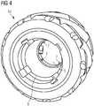
- Fig. 4 shows a motor-driven wheel 2, which is designed as an omnidirectional wheel 15, in an interior view or from its rear side, the rear side being the end face of the motor-driven wheel 2 facing the mobile medical device 1.
- the omnidirectional wheel 15 is designed as a mecanum wheel.
- a frusto-conical recess 8 is formed in the interior of the motor-driven wheel, i.e. the omnidirectional wheel 15, or in its inner circumference, this frustoconical recess 8 being designed to correspond and precisely fit the frustoconical design of the hub 9, as in Fig. 5 can be seen and is explained in more detail below.
- the locking device 5 can be seen, which has guide elements 6.
- the guide elements 6 can, for example, as in FIG Fig. 4 shown, be designed as pins.
- Fig. 5 shows a hub 9 belonging to the motor-driven wheel 2, which carries the motor-driven wheel 2 on its outer surface and is designed in the shape of a truncated cone in the present exemplary embodiment.
- Grooves 10 and anti-rotation elements 11 are formed on the circumference of the hub, which ensure that the motor-driven wheel 2 cannot rotate relative to the hub 9, either during operation or when locking.
- the motor-driven wheel 2 can be inserted and cleaned, for example, in a dishwashing or cleaning machine commonly used in clinical settings.
- the motor-driven wheel 2 can also be replaced immediately by a motor-driven wheel 2 that has already been cleaned.
- the locking device 5 is used to securely remove and fasten the motor-driven wheel 2, for example in the context of cleaning the motor-driven wheel 2.
- this is designed to be rotatable.
- helix-shaped grooves 10 are attached and at the same time attached to the corresponding counterpart, i.e. either on the rotatable locking device 5 or on the circumference of the hub 9, guide elements 7.
- the guide elements 7 cause When the locking device 5 is rotated, an axial displacement of the motor-driven wheel 2.
- the locking device 5 pushes and fixes the motor-driven wheel 2 on the hub 9 when it is rotated or detaches it from the hub 9 when it is rotated in the opposite direction.
- the locking and unlocking is implemented by locking elements, such as, for example, balls, which are pressed into the grooves 10 which are arranged on the circumference of the hub 9.
- the guide elements 7 are fixed in a detent position by an axially displaceable or rotatable sleeve on the motor-driven wheel 2 or in the hub 9.
- a centrally arranged foldable hook which pulls the motor-driven wheel 2 onto a sleeve described in the above paragraph and fixes it there, is locked.
- the centrally arranged foldable hook can be designed in such a way that it unlocks the motor-driven wheel 2 by actuation in the opposite direction and thus pushes it down from the hub 9.
- the grip element 6 can, for example, be designed as a handle and at the same time be designed to carry the wheel. This results in the advantage that the grip element 6 is sufficient on its own for releasing and carrying.
- the hub 5 can on its circumference with the at least one anti-rotation element 11, as in Fig. 5 can be seen to be equipped.
- An embodiment of the anti-rotation element 11 can be provided by an element protruding on the circumference of the hub 9, for example milled or screwed on, which can for example be octagonal formed.
- grooves are provided in the inner circumference of the motor-driven wheel 2, in which the anti-rotation elements 11 act. If an anti-rotation element 11 and grooves 10 are formed on the circumference of the hub 9 at the same time, these can each be attached to the different ends of the hub 9. For example, there are then on the outer, smaller - if the hub 9 is frustoconical, circumference of the hub 9, that is, the side facing away from the mobile medical device 1, the grooves 10 and on the opposite side, that is, on the outer, larger circumference - if the The hub 9 is frustoconical, that is to say the anti-rotation elements 11 on the side facing away from the mobile medical device 1.
- the fold-out handle element 6 of the locking device 5 is used to actuate the locking device 5.
- the fold-out handle element 6 can be designed as a fold-out handle so that the unlocked and removed motor-driven wheel 2 can be carried directly on this handle element 6 without the hassle of reaching around. This results in a significant advantage, since the motor-driven wheel 2 can be removed with bare hands and entirely without additional aids, such as tools.
- the fold-out handle element 6 can be designed in such a way that it can only be folded into its starting position when the motor-driven wheel 2 is attached, when the locking device 5 is in its locked end position, i.e. with the motor-driven wheel 2 firmly mounted Cams on the locking device 5 and corresponding depressions on the hub 9 can be achieved in the locking position. This also has a safety-relevant effect itself, since an inadvertently incomplete locking of the motor-driven wheel 2 is immediately visible.
- the cover element 4 of the motor-driven wheel 2 can, for example, when changing a wheel, folded over, i.e. be opened. In one embodiment, however, the cover element 4 can only be folded back into the starting position, i.e. closed position, if the motor-driven wheel 2 has been pushed completely to the correct axial position of the hub 9 and the grip element 7 of the locking device 5 has been folded in.
Landscapes
- Engineering & Computer Science (AREA)
- Mechanical Engineering (AREA)
- Health & Medical Sciences (AREA)
- Life Sciences & Earth Sciences (AREA)
- Animal Behavior & Ethology (AREA)
- Veterinary Medicine (AREA)
- Public Health (AREA)
- General Health & Medical Sciences (AREA)
- Nursing (AREA)
- Transportation (AREA)
- Combustion & Propulsion (AREA)
- Chemical & Material Sciences (AREA)
- Biomedical Technology (AREA)
- Medical Informatics (AREA)
- Apparatus For Radiation Diagnosis (AREA)
- Accommodation For Nursing Or Treatment Tables (AREA)
- Optics & Photonics (AREA)
- Physics & Mathematics (AREA)
- Biophysics (AREA)
- High Energy & Nuclear Physics (AREA)
- Arrangement Or Mounting Of Propulsion Units For Vehicles (AREA)
- Nuclear Medicine, Radiotherapy & Molecular Imaging (AREA)
- Pathology (AREA)
- Radiology & Medical Imaging (AREA)
- Heart & Thoracic Surgery (AREA)
- Molecular Biology (AREA)
- Surgery (AREA)
- Dental Tools And Instruments Or Auxiliary Dental Instruments (AREA)
- Invalid Beds And Related Equipment (AREA)
Description
- Mobiles medizinisches Gerät mit mindestens einem motorisch angetriebenen Rad
- Die Erfindung betrifft ein mobiles medizinisches Gerät, das mit Hilfe von motorisch angetriebenen Rädern auf einer Bodenoberfläche verfahrbar ist. Bei dem medizinischen Gerät handelt es sich beispielsweise um eine Patientenliege oder ein C-Bogen Röntgengerät.
- Mobile medizinische Geräte weisen in der Regel ein Fahrwerk mit manuell oder motorisch angetriebenen Rädern auf und werden in medizinischen Bereichen vor allem in Operationssälen verwendet. Die Bodenoberfläche kann in einer derartigen Umgebung beispielsweise durch Körperflüssigkeiten, Spülflüssigkeiten oder Verbrauchsmaterial verunreinigt sein.
- Die Offenlegungsschrift
US 2014/0379130 A1 offenbart beispielsweise die Verwendung von Mecanum-Rädern für mobile medizinische Geräte. Diese sind aufgrund ihrer guten Manövrierbarkeit besonders für die Nutzung im klinischen Umfeld geeignet. - Das Mecanum-Rad ist ein Rad, das einem damit ausgestatteten Fahrzeug omnidirektionale Fahrmanöver erlaubt, ohne mit einer mechanischen Lenkung ausgestattet sein zu müssen. Auf dem Umfang des Rades sind mehrere drehbar gelagerte tonnenförmige Rollen meist im Winkel von 45 Grad zur Achse des gesamten Rades angebracht. Ausschließlich diese Rollen stellen den Kontakt zur Bodenoberfläche her. Die Rollen haben keinen direkten eigenen Antrieb und können sich frei um ihre schräge Lagerachse drehen. Das gesamte Mecanum-Rad wird von einem Antriebsmotor mit veränderbarer Drehrichtung und variabler Drehzahl angetrieben. Um das omnidirektionale Fahrmanöver zu realisieren, werden die Drehzahl und die Drehrichtung eines jeden Rades einzeln angesteuert.
- In der Gebrauchsmusterschrift
CN 203226834 U wird ein mobiles C-Bogen Röntgengerät mit omnidirektionalen Rädern offenbart und das Wirkprinzip der individuellen Ansteuerung eines jeden Rades erläutert. - Motorisch angetriebene Räder und omnidirektionale Räder, wie beispielsweise die Mecanum-Räder, sind aufgrund ihrer Struktur oder ihrer Befestigung schwer zu reinigen. Es ist üblich, den Boden und die Geräte in einem Operationssaal durch Abwischen zu reinigen und diese in bestimmten Zeitabständen einer besonders gründlichen Reinigung und Desinfektion zu unterziehen. Eine gründliche Reinigung der Räder ist schwer möglich.
- Um die Nutzung mobiler medizinischer Geräte, wie C-Bogen Röntgengeräte und mobile Patientenliegen, vor allem während chirurgischer Eingriffe zu erleichtern, sind Maßnahmen zur Verringerung der Kontaminationsgefahr der mobilen medizinischen Geräte zu treffen.
- In der Patentanmeldung
US 2014/054952 A1 ist eine schnell lösbare Naben-und-Rad-Anordnung offenbart. Die Anordnung umfasst Innen- und Außenhülsen, die um einen drehbaren Verriegelungsring angeordnet sind. Der Verriegelungsring ist in eine verriegelte Position vorspannbar und vorübergehend in eine entriegelte Position bringbar. - In der Patentschrift
US 8 549 705 B1 ist ein Hohlradsatz beschrieben, der ein hohles Drehrad, ein Zahnrad, eine Begrenzungshülse sowie einen Begrenzungs- und Befestigungsring umfasst. Die Radhalterung weist einen Befestigungsarm auf, an dem eine Radgabel vorgesehen ist. Das hohle Drehrad ist auf die Radgabel aufgezogen. - Die Patentschrift
DE 19949408 C1 beschreibt, dass ein Antriebsrad umfassend eine Radnabe über eine Steckachse an einem mobilen medizinischen Gerät in Form eines Rollstuhls, insbesondere an seinem Rollstuhlgestell befestigt werden kann. Dazu ist ein Mechanismus umfassend Sperrkugeln vorgesehen, die über ein Betätigungselement in Form eines manuell zu bewegenden Bügels betätigt und zwischen einer Verriegelungsposition und einer Freigabeposition verstellt werden kann. In der Verriegelungsposition des Bügels besteht eine sichere Verbindung zwischen Antriebsrad und Fahrzeuggestell. Ein Antrieb des Antriebsrades mittels Elektromotor wird verhindert, sofern die Verbindung nicht sicher ist. - Es ist Aufgabe der Erfindung, ein mobiles medizinisches Gerät mit motorisch angetriebenen Rädern anzugeben, das in einer verunreinigten Umgebung eingesetzt werden kann.
- Gemäß der Erfindung wird die gestellte Aufgabe mit dem mobilen medizinischen Gerät mit mindestens einem motorisch angetriebenen Rad des unabhängigen Patentanspruchs gelöst. Vorteilhafte Weiterbildungen sind in den abhängigen Ansprüchen angegeben.
- Erfindungsgemäß wird das motorisch angetriebene Rad so ausgebildet, dass es mit bloßen Händen, das heißt von Hand und ohne Hilfsmittel, wie Werkzeuge, von einer drehbaren Nabe des mobilen medizinischen Geräts abziehbar und wieder aufsteckbar ist.
- Die Erfindung beansprucht ein mobiles medizinisches Gerät mit mindestens einem motorisch angetriebenen Rad, mit dem das mobile medizinische Gerät verfahrbar ist. Das motorisch angetriebene Rad ist auf einer dem motorisch angetriebenen Rad zugehörigen Nabe angeordnet und kann von Hand und ohne Hilfsmittel reversibel von der Nabe abgenommen und reversibel auf die Nabe aufgesteckt werden. Weiterhin umfasst das motorisch angetriebene Rad eine Verriegelungsvorrichtung, mit welcher das motorisch angetriebene Rad lösbar fest mit der Nabe verbindbar ist und von der Nabe gelöst werden kann. Darüber hinaus weist die Verriegelungsvorrichtung ein ausklappbares Griffelement auf, das an der dem medizinischen Gerät abgewandten Stirnfläche des motorisch angetriebenen Rads angeordnet ist.
- Die Erfindung bietet den Vorteil, dass zum Reinigen des motorisch angetriebenen Rads dieses sehr einfach von dem medizinischen Gerät entfernt und beispielsweise in einer geeigneten Wasch- und Desinfektionseinrichtung gereinigt werden kann.
- In einer Ausführungsform der Erfindung ist das motorisch angetriebene Rad als omnidirektionales Rad ausgebildet.
- In einer Weiterbildung ist die Nabe drehbar auf einer Achse des mobilen medizinischen Gerätes gelagert.
- Des Weiteren können auf dem Umfang der Nabe Nuten angeordnet sein und in diese Nuten korrespondierende Führungselemente der Verriegelungsvorrichtung eingreifen, wobei die Verriegelungsvorrichtung verdrehbar ausgebildet ist.
- In einer weiteren Ausführungsform weist die verdrehbare Verriegelungsvorrichtung Nuten auf und auf dem Umfang der Nabe sind in die Nuten eingreifende korrespondierende Führungselemente angeordnet.
- In einer weiteren Ausführungsform können die Verriegelungsvorrichtung und die Nabe derart ausgebildet sein, dass das Griffelement nur in einer verriegelten Position des motorisch angetriebenen Rads einklappbar ist.
- In einer Weiterbildung der Erfindung weist das medizinische Gerät ein über das motorisch angetriebene Rad klappbares schutzblechartiges Abdeckelement auf. Das Abdeckelement ist nur in einer verriegelten Position des motorisch angetriebenen Rads klappbar.
- In einer Weiterbildung der Erfindung weist das mobile medizinische Gerät eine Hebevorrichtung auf, die das motorisch angetriebene Rad von einer Bodenoberfläche abheben kann.
- In einer weiteren Ausführungsform der Erfindung ist in der Achse ein Elektromotor angeordnet, der das motorisch angetriebene Rad antreibt.
- Das mobile medizinische Gerät kann außerdem mindestens ein nicht motorisch angetriebenes weiteres Rad aufweisen, mit dem das mobile medizinische Gerät bei einem angehobenen motorisch angetriebenen Rad verfahrbar ist.
- In einer weiteren Ausführungsform weist das mobile medizinische Gerät mindestens vier omnidirektionale Räder auf, wobei diese als Mecanum-Räder ausgebildet sind.
- In einer Weiterbildung der Erfindung ist die Nabe kegelstumpfförmig ausgebildet und das motorisch angetriebene Rad weist eine korrespondierende kegelstumpfförmige Vertiefung auf.
- In einer weiteren Ausführungsform der Erfindung ist auf dem Umfang der Nabe mindestens ein Verdrehsicherungselement angeordnet, welches das motorisch angetriebene Rad verdrehsicher auf der Nabe hält.
- Weitere Besonderheiten und Vorteile der Erfindung werden aus den nachfolgenden Erläuterungen eines Ausführungsbeispiels anhand von schematischen Zeichnungen ersichtlich.
- Es zeigen:
- Fig. 1:
- ein mobiles medizinisches Gerät mit mindestens einem motorisch angetriebenen Rad,
- Fig. 2:
- ein motorisch angetriebenes Rad im axialen Schnitt,
- Fig. 3:
- ein motorisch angetriebenes Rad in einer Außenansicht,
- Fig. 4:
- ein motorisch angetriebenes Rad als omnidirektionales Rad in einer Innenansicht und
- Fig. 5:
- eine räumliche Ansicht einer Nabe.
-
Fig. 1 zeigt ein mobiles medizinisches Gerät 1 mit mindestens einem motorisch angetriebenen Rad 2. In diesem Ausführungsbeispiel weist das mobile medizinische Gerät 1 vier durch jeweils einen eigenen Elektromotor 3 motorisch angetriebene Räder 2 auf. - Zusätzlich ist in dieser Ausführungsform ein schutzblechartiges klappbares Abdeckelement 4 über dem motorisch angetriebenen Rad 2 angeordnet, das in geöffneter Position zu sehen ist. In geschlossener Position, das heißt in der heruntergeklappten Position, kann das Abdeckelement 4 schmutzabweisend und zusätzlich als Kabelabweiser wirken.
-
Fig. 1 zeigt außerdem das mobile medizinische Gerät 1 mit einer Hebevorrichtung 13 der motorisch angetriebenen Räder 2 und mit vier weiteren Rädern 12, die nicht motorisch angetrieben sind. - Um einen Radwechsel schnell und ohne zusätzliche Hilfsmittel ausführen zu können, besitzt jedes motorisch angetriebene Rad 2 eine Hebevorrichtung 13. Damit kann jedes motorisch angetriebene Rad 2 einzeln von einer Bodenoberfläche abgehoben werden. Dabei stützt sich bei einem Radwechsel das mobile medizinische Gerät 1 auf den verbleibenden nicht angehobenen motorisch angetriebenen Rädern 2 auf dem Boden ab. Bei dieser nicht dargestellten Ausführungsform werden keine zusätzlichen Räder 12 oder beispielsweise Stützen benötigt.
- In einer weiteren Ausführungsform können alle motorisch angetriebenen Räder 2 gleichzeitig von den Hebevorrichtungen 13 von der Bodenoberfläche abgehoben werden. Dabei besitzt das mobile medizinische Gerät 1 einen weiteren, zweiten Radsatz bestehend aus mindestens zwei nicht motorisch angetriebenen Rädern 12 oder Stützen, auf dem oder denen sich das mobile medizinische Gerät 1 auf der Bodenoberfläche abstützen kann. Die angehobenen motorisch angetriebenen Räder 2 stehen folglich frei und können abgenommen werden.
- In einer weiteren Ausführungsform der Hebevorrichtung 13 ist diese derart ausgebildet, dass die auszuwechselnden motorisch angetriebenen Räder 2 relativ zu einem Fahrwerk des mobilen medizinischen Geräts 1 auf einer unveränderten Höhe bleiben. Ein Fachmann in dem vorliegenden Bereich der Technik versteht unter einem Fahrwerk die Gesamtheit aller Teile eines fahrbaren Gerätes, die der Verbindung des Aufbaus des fahrbaren Gerätes über die, in diesem Fall motorisch angetriebenen, Räder 2, zur Fahrbahn dienen. Dabei kann dann das gesamte Fahrwerk mit Hilfe von zusätzlichen Rädern 12 oder Stützen von der Bodenoberfläche abgehoben werden.
- Vorzugsweise besitzt das mobile medizinische Gerät 1 einen zweiten Radsatz, also mindestens drei weitere, nicht motorisch angetriebene Räder 12, da diese bei einem Versagen des motorischen Antriebs durch die Elektromotoren 3 der motorisch angetriebenen Räder 2 dafür sorgen können, dass das mobile medizinische Gerät 1 trotzdem bewegt werden kann und diese somit sicherheitstechnisch relevant sind.
- In einem nicht dargestellten Ausführungsbeispiel weist das mobile medizinische Gerät 1 vier motorisch angetriebene Räder 2 in Form von omnidirektionalen Rädern 15 auf, beispielsweise Mecanum-Räder. Bei Mecanum-Rädern werden die Drehrichtung und die Drehzahl jedes einzelnen Rads getrennt gesteuert. Dies bietet den Vorteil einer optimalen Manövrierbarkeit, besonders in engen Räumen, wie es in Operationssälen oft der Fall ist.
-
Fig. 2 zeigt das motorisch angetriebene Rad 2, die Nabe 9, die Achse 14 und den Elektromotor 3 im axialen Schnitt. Der Elektromotor 3 befindet sich bei der dargestellten Ausführungsform in der Achse 14, die deshalb als Hohlachse oder auch als Rohr ausgeführt ist. Dabei sitzt jeweils das motorisch angetriebene Rad 2 auf einer diesem motorisch angetriebenen Rad 2 zugehörigen Nabe 9, die drehbar auf der Achse 14 gelagert ist. Dies kann durch Radlager, beispielsweise in Form von Kugellagern, ausgeführt werden. Der Elektromotor 3 treibt so über ein Getriebe und einen oder mehrere Mitnehmer, beispielsweise durch Mitnehmerstifte oder bekannte andere Mittel zur Ausführung eines Mitnehmers, die Nabe 3 an, die das Drehmoment auf das motorisch angetriebene Rad 2 überträgt. -
Fig. 3 zeigt ein motorisch angetriebenes Rad 2 in einer Außenansicht. Das motorisch angetriebene Rad 2 weist eine konzentrisch in das motorisch angetriebene Rad 2 integrierte Verriegelungsvorrichtung 5 auf, wobei die Verriegelungsvorrichtung 5 ein ausklappbares Griffelement 5 auf der Stirnseite aufweist. -
Fig. 4 zeigt ein motorisch angetriebenes Rad 2, das als omnidirektionales Rad 15 ausgebildet ist, in einer Innenansicht bzw. von seiner Rückseite, wobei die Rückseite die sich dem mobilen medizinischen Gerät 1 zuwendende Stirnfläche des motorisch angetriebenen Rads 2 ist. Insbesondere ist das omnidirektionale Rad 15 als Mecanum-Rad ausgebildet. In dieser Ausführungsform ist im Inneren des motorisch angetriebenen Rads, also des omnidirektionalen Rads 15, beziehungsweise in seinem inneren Umfang, eine kegelstumpfförmige Vertiefung 8 ausgebildet, wobei diese kegelstumpfförmige Vertiefung 8 korrespondierend und passgenau zur kegelstumpfförmigen Ausbildung der Nabe 9 ausgebildet ist, wie inFig. 5 zu sehen ist und im Weiteren näher erläutert wird. Des Weiteren ist die Verriegelungsvorrichtung 5 zu sehen, die Führungselemente 6 aufweist. Die Führungselemente 6 können beispielsweise, wie in derFig. 4 dargestellt, als Stifte ausgebildet sein. -
Fig. 5 zeigt eine dem motorisch angetriebenen Rad 2 zugehörige Nabe 9, die auf ihrer Mantelfläche das motorisch angetriebene Rad 2 trägt und in dem vorliegenden Ausführungsbeispiel kegelstumpfförmig ausgebildet ist. Am Umfang der Nabe sind Nuten 10 und Verdrehsicherungselemente 11 ausgebildet, die dafür sorgen, dass sich das motorisch angetriebene Rad 2 sowohl im Betrieb als auch beim Verriegeln nicht gegenüber der Nabe 9 verdrehen kann. - Bezugnehmend auf die
Fig. 3 ,Fig. 4 undFig. 5 wird im Weiteren das Funktionsprinzip des Abnehmens und Aufsteckens des motorisch angetriebenen Rads 2 von der Nabe 9 beschrieben. Dabei bleibt während eines gesamten Wechselvorgangs die drehbar gelagerte Nabe 9 auf der Achse 14 am Fahrwerk. Im Rahmen des Radwechsels wird also nur das motorisch angetriebene Rad 2, wie inFig. 4 am Beispiel des omnidirektionalen Rads 15 zu sehen, abgenommen. - Somit ist bei Bedarf eine vollständige und lückenlose Reinigung des motorisch angetriebenen Rads 2 möglich, indem dieses beispielsweise in einer im klinischen Umfeld gebräuchlichen Spül- oder Reinigungsmaschine eingelegt und gereinigt werden kann. Das motorisch angetriebene Rad 2 kann aber auch sofort durch ein bereits gereinigtes motorisch angetriebenes Rad 2 ersetzt werden.
- Die Verriegelungsvorrichtung 5 dient zum sicheren Abnehmen und Befestigen des motorisch angetriebenen Rads 2, beispielsweise im Rahmen einer Reinigung des motorisch angetriebenen Rads 2.
- In einer Ausführungsform der Verriegelungsvorrichtung 5 ist diese verdrehbar ausgebildet. Dabei sind am Umfang der Nabe 9 oder in der verdrehbaren Verriegelungsvorrichtung 5, beispielsweise Helix-förmige, Nuten 10 angebracht und gleichzeitig am entsprechenden Gegenstück, also entweder an der verdrehbaren Verriegelungsvorrichtung 5 oder am Umfang der Nabe 9 Führungselemente 7 angebracht. Die Führungselemente 7 bewirken bei einem Verdrehen der Verriegelungsvorrichtung 5 eine axiale Verschiebung des motorisch angetriebenen Rads 2. Somit schiebt und fixiert die Verriegelungsvorrichtung 5 bei Verdrehen das motorisch angetriebene Rad 2 auf die Nabe 9 oder löst es von der Nabe 9 bei Verdrehen in die entgegengesetzte Richtung.
- In einer weiteren nicht dargestellten Ausführungsform der Verriegelungsvorrichtung 5 wird die Ver- und Entriegelung durch Verriegelungselemente realisiert, wie beispielsweise Kugeln, die in die Nuten 10, die auf dem Umfang der Nabe 9 angeordnet sind, gedrückt werden. Durch eine axial verschiebbare oder drehbare Hülse am motorisch angetriebenen Rad 2 bzw. in der Nabe 9 werden die Führungselemente 7 in einer Raststellung fixiert.
- In einer weiteren nicht dargestellten Ausführungsform der Verriegelungsvorrichtung 5 wird beispielsweise mit einem zentral angeordneten klappbaren Haken, der das motorisch angetriebene Rad 2 bei Betätigung auf eine im obigen Absatz beschriebene Hülse zieht und dort fixiert, verriegelt. Der zentral angeordnete klappbare Haken kann derart ausgeführt werden, dass er durch eine entgegengesetzte Betätigung das motorisch angetriebene Rad 2 entriegelt und somit von der Nabe 9 herunter schiebt. Dabei kann zur Betätigung das Griffelement 6 beispielsweise als Handgriff ausgeführt und gleichzeitig zum Tragen des Rads ausgebildet sein. Daraus ergibt sich der Vorteil, dass das Griffelement 6 allein zum Lösen und Tragen ausreicht.
- Damit bei Betätigung der Verriegelungsvorrichtung 5, wenn diese verdrehbar ausgeführt ist, sich das motorisch angetriebene Rad 2 nicht relativ zur Nabe 9 verdreht, kann die Nabe 5 auf ihrem Umfang mit dem mindestens einem Verdrehsicherungselement 11, wie in
Fig. 5 ersichtlich, ausgestattet sein. Eine Ausführungsform des Verdrehsicherungselements 11 kann durch ein auf dem Umfang der Nabe 9 herausragendes, beispielsweise ausgefrästes oder angeschraubtes, Element, das beispielsweise achteckig ausgebildet sein kann, gebildet werden. - Korrespondierend dazu sind im inneren Umfang des motorisch angetriebenen Rads 2 Nuten angebracht, in welche die Verdrehsicherungselemente 11 wirken. Sind auf dem Umfang der Nabe 9 gleichzeitig ein Verdrehsicherungselement 11 und Nuten 10 ausgebildet, können diese jeweils an den unterschiedlichen Enden der Nabe 9 angebracht sein. Beispielsweise befinden sich dann am äußeren, kleineren - falls die Nabe 9 kegelstumpfförmig ausgebildet ist, Umfang der Nabe 9, also der dem mobilen medizinischen Gerät 1 abgewandten Seite, die Nuten 10 und auf der entgegengesetzten Seite, also am äußeren, größeren Umfang - falls die Nabe 9 kegelstumpfförmig ausgebildet ist, also der dem mobilen medizinischen Gerät 1 abgewandten Seite die Verdrehsicherungselemente 11.
- Das ausklappbare Griffelement 6 der Verriegelungsvorrichtung 5 dient der Betätigung der Verriegelungsvorrichtung 5. Dabei kann das ausklappbare Griffelement 6 als ausklappbarer Handgriff ausgebildet sein, sodass das entriegelte und abgenommene motorisch angetriebene Rad 2 ohne lästiges Umgreifen direkt an diesem Griffelement 6 getragen werden kann. Hieraus ergibt sich ein wesentlicher Vorteil, da das motorisch angetriebene Rad 2 mit bloßen Händen und ganz ohne zusätzliche Hilfsmittel, wie beispielsweise Werkzeuge, abgenommen werden kann.
- Das ausklappbare Griffelement 6 kann so ausgeführt sein, dass dieses nur bei einem aufgesetzten motorisch angetriebenen Rad 2 in seine Ausgangstellung eingeklappt werden kann, wenn die Verriegelungsvorrichtung 5 in ihrer verriegelten Endposition steht, also bei fest montiertem motorisch angetriebenen Rad 2. Dies kann beispielsweise durch exzentrische Nocken an der Verriegelungsvorrichtung 5 und entsprechende Vertiefungen an der Nabe 9 in der Verriegelungsposition erreicht werden. Dies bringt zusätzlich einen sicherheitsrelevanten Effekt mit sich, da dadurch eine versehentlich unvollständige Verriegelung des motorisch angetriebenen Rads 2 sofort sichtbar wird.
- Das Abdeckelement 4 des motorisch angetriebenen Rads 2 kann, beispielsweise bei einem Radwechsel, umgeklappt, d.h. geöffnet werden. In einer Ausführungsform ist das Zurückklappen in die Ausgangstellung, also geschlossene Stellung, des Abdeckelements 4 jedoch nur dann möglich, wenn das motorisch angetriebene Rad 2 vollständig auf die korrekte Axialposition der Nabe 9 geschoben und das Griffelement 7 der Verriegelungsvorrichtung 5 eingeklappt ist.
- Obwohl die Erfindung im Detail durch die Ausführungsbeispiele näher illustriert und beschrieben wurde, ist die Erfindung durch die offenbarten Beispiele nicht eingeschränkt und andere Variationen können vom Fachmann daraus abgeleitet werden, ohne den Schutzumfang der Erfindung zu verlassen.
-
- 1
- mobiles medizinisches Gerät
- 2
- motorisch angetriebenes Rad
- 3
- Elektromotor
- 4
- Abdeckelement
- 5
- Verriegelungsvorrichtung
- 6
- Griffelement
- 7
- Führungselemente
- 8
- kegelstumpfförmige Vertiefung
- 9
- Nabe
- 10
- Nut
- 11
- Verdrehsicherungselement
- 12
- weiteres Rad
- 13
- Hebevorrichtung
- 14
- Achse
- 15
- omnidirektionales Rad
Claims (13)
- Mobiles medizinisches Gerät (1) mit mindestens einem motorisch angetriebenen Rad (2), mit dem das mobile medizinische Gerät (2) verfahrbar ist, wobei- das motorisch angetriebene Rad (2) auf einer dem motorisch angetriebenen Rad (2) zugehörigen Nabe (9) angeordnet ist, gekennzeichnet dadurch, dass- das motorisch angetriebene Rad (2) von Hand und ohne Hilfsmittel reversibel von der Nabe (9) abnehmbar und wieder auf die Nabe (9) steckbar ist, wobei das mobile medizinische Gerät weiter umfasst:- eine Verriegelungsvorrichtung (5) des motorisch angetriebenen Rads (2), die ausgebildet ist, das motorisch angetriebene Rad (2) mit der Nabe (9) lösbar fest zu verbinden und von der Nabe (9) zu lösen,- ein ausklappbares Griffelement (6) der Verriegelungsvorrichtung (5), das an der dem medizinischen Gerät (1) abgewandten Stirnfläche des motorisch angetriebenen Rads (2) angeordnet ist.
- Mobiles medizinisches Gerät (1) nach Anspruch 1,
dadurch gekennzeichnet,
dass das motorisch angetriebene Rad (2) ein omnidirektionales Rad (15) ist. - Mobiles medizinisches Gerät nach Anspruch 1 oder 2, gekennzeichnet durch:- eine Achse (14), auf der die Nabe (9) drehbar gelagert angeordnet ist.
- Mobiles medizinisches Gerät nach Anspruch 1, gekennzeichnet durch:- Nuten (10) auf dem Umfang der Nabe und- in die Nuten (10) eingreifende korrespondierende Führungselemente (11) der Verriegelungsvorrichtung (5), wobei die Verriegelungsvorrichtung (5) verdrehbar ausgebildet ist.
- Mobiles medizinisches Gerät nach Anspruch 1, gekennzeichnet durch:- Nuten (10) in der Verriegelungsvorrichtung (5), wobei die Verriegelungsvorrichtung (5) verdrehbar ausgebildet ist, und- in die Nuten (10) eingreifende korrespondierende Führungselemente (11) auf dem Umfang der Nabe (9).
- Mobiles medizinisches Gerät nach Anspruch 1,
dadurch gekennzeichnet,
dass die Verriegelungsvorrichtung (5) und die Nabe (9) derart ausgebildet sind, dass das Griffelement (6) nur in einer verriegelten Position des motorisch angetriebenen Rads (2) einklappbar ist. - Mobiles medizinisches Gerät nach einem der vorhergehenden Ansprüche,
gekennzeichnet durch:- ein über das motorisch angetriebene Rad (2) klappbares schutzblechartiges Abdeckelement (4), das ausgebildet ist, nur in einer verriegelten Position des motorisch angetriebenen Rads (2) über das motorisch angetriebene Rad (2) zu klappen. - Mobiles medizinisches Gerät nach einem der vorhergehenden Ansprüche,
gekennzeichnet durch:- eine Hebevorrichtung (13), die ausgebildet ist, das motorisch angetriebene Rad (2) von einer Bodenoberfläche abzuheben. - Mobiles medizinisches Gerät nach einem der Ansprüche 3 bis 8,
gekennzeichnet durch:- einen in der Achse (14) angeordneten Elektromotor (3), der ausgebildet ist, das motorisch angetriebene Rad (2) anzutreiben. - Mobiles medizinisches Gerät nach einem der vorhergehenden Ansprüche,
gekennzeichnet durch:- mindestens ein nicht motorisch angetriebenes weiteres Rad (12), mit dem das mobile medizinische Gerät (1) bei einem abgehobenen motorisch angetriebenen Rad (2) verfahrbar ist. - Mobiles medizinisches Gerät nach Anspruch 2 bis 10, gekennzeichnet durch:- mindestens vier omnidirektionale Räder (15), die als Mecanum-Räder ausgebildet sind.
- Mobiles medizinisches Gerät nach einem der vorhergehenden Ansprüche,
dadurch gekennzeichnet,
dass die Nabe (9) kegelstumpfförmig ausgebildet ist und dass das motorisch angetriebene Rad (2) eine korrespondierende kegelstumpfförmige Vertiefung (8) aufweist. - Mobiles medizinisches Gerät nach einem der vorhergehenden Ansprüche,
gekennzeichnet durch:- mindestens ein am Umfang der Nabe (9) angeordnetes Verdrehsicherungselement (11), das ausgebildet ist, das motorisch angetriebene Rad (2) verdrehsicher auf der Nabe (9) zu halten.
Applications Claiming Priority (2)
| Application Number | Priority Date | Filing Date | Title |
|---|---|---|---|
| DE102015206909.5A DE102015206909A1 (de) | 2015-04-16 | 2015-04-16 | Mobiles medizinisches Gerät mit mindestens einem motorisch angetriebenen Rad |
| PCT/EP2016/056515 WO2016165925A1 (de) | 2015-04-16 | 2016-03-24 | Mobiles medizinisches gerät mit mindestens einem motorisch angetriebenen rad |
Publications (2)
| Publication Number | Publication Date |
|---|---|
| EP3242802A1 EP3242802A1 (de) | 2017-11-15 |
| EP3242802B1 true EP3242802B1 (de) | 2020-08-19 |
Family
ID=55661388
Family Applications (1)
| Application Number | Title | Priority Date | Filing Date |
|---|---|---|---|
| EP16714334.6A Not-in-force EP3242802B1 (de) | 2015-04-16 | 2016-03-24 | Mobiles medizinisches gerät mit mindestens einem motorisch angetriebenen rad |
Country Status (6)
| Country | Link |
|---|---|
| US (1) | US11001098B2 (de) |
| EP (1) | EP3242802B1 (de) |
| JP (1) | JP6761812B2 (de) |
| CN (1) | CN107567317A (de) |
| DE (1) | DE102015206909A1 (de) |
| WO (1) | WO2016165925A1 (de) |
Families Citing this family (9)
| Publication number | Priority date | Publication date | Assignee | Title |
|---|---|---|---|---|
| US11058378B2 (en) * | 2016-02-03 | 2021-07-13 | Globus Medical, Inc. | Portable medical imaging system |
| JP2018131068A (ja) * | 2017-02-15 | 2018-08-23 | ナブテスコ株式会社 | 運搬台車用の駆動装置 |
| US11039964B2 (en) * | 2017-03-06 | 2021-06-22 | Stryker Corporation | Systems and methods for facilitating movement of a patient transport apparatus |
| CN206623628U (zh) * | 2017-04-07 | 2017-11-10 | 深圳市大疆创新科技有限公司 | 轮组装置及移动装置 |
| GB2566017B (en) * | 2017-08-29 | 2020-06-17 | Q Bot Ltd | Robotic vehicle |
| DE102018211669B4 (de) | 2018-07-12 | 2020-01-23 | Siemens Healthcare Gmbh | Omnidirektionales Fahrwerk für eine Gantry eines Computertomographiegeräts |
| US11690582B2 (en) | 2020-05-06 | 2023-07-04 | GE Precision Healthcare LLC | Systems and methods for a mobile medical device drive platform |
| WO2022048611A1 (en) * | 2020-09-02 | 2022-03-10 | Shanghai United Imaging Healthcare Co., Ltd. | Mobile medical device |
| EP4422884A4 (de) * | 2021-10-27 | 2025-10-29 | Iw Tech Llc | Universalschleuderrad |
Citations (1)
| Publication number | Priority date | Publication date | Assignee | Title |
|---|---|---|---|---|
| DE19949408C1 (de) * | 1999-10-13 | 2000-10-12 | Alber Ulrich Gmbh & Co Kg | Fahrzeug, insbesondere Rollstuhl |
Family Cites Families (29)
| Publication number | Priority date | Publication date | Assignee | Title |
|---|---|---|---|---|
| US2026586A (en) * | 1934-03-31 | 1936-01-07 | Thomas C Mcveagh | Securing device |
| JPS4426357Y1 (de) | 1965-10-22 | 1969-11-05 | ||
| JPS4612813Y1 (de) | 1967-03-30 | 1971-05-07 | ||
| US3944285A (en) * | 1973-05-23 | 1976-03-16 | Gerald Vincent | Wheel safety lock |
| US4347907A (en) * | 1978-09-11 | 1982-09-07 | Downing Jr James H | All-electric A.C. tractor |
| GB2169055B (en) * | 1984-12-22 | 1988-08-17 | Unisys Corp | Improved hub assembly |
| JP3009470U (ja) | 1994-09-26 | 1995-04-04 | 株式会社澤村製作所 | 2部材の連結構造 |
| CA2328858A1 (en) * | 1998-04-17 | 1999-10-28 | Tract-A-Pillar Tractor Co., Inc. | Earth-based vehicle |
| US6173481B1 (en) * | 1998-06-23 | 2001-01-16 | Michael B. Parent | Wheel removal and reassembly apparatus for brake access on heavy vehicles |
| JP2002046670A (ja) | 2000-08-02 | 2002-02-12 | Yanmar Agricult Equip Co Ltd | 六輪作業車 |
| US6813939B1 (en) * | 2002-06-24 | 2004-11-09 | Laray A. Wilcoxon | Vehicle repair ramps with integral rolling system |
| US6802570B2 (en) * | 2002-09-27 | 2004-10-12 | Load Rite Trailers, Inc. | Oriented roller bushing for boat trailer |
| JP2004176874A (ja) | 2002-11-29 | 2004-06-24 | Yamada Kogyo Kk | 連結装置 |
| GB2400084A (en) * | 2003-03-31 | 2004-10-06 | Karbon Kinetics Ltd | Bicycle hub assembly |
| JP3820239B2 (ja) * | 2003-08-22 | 2006-09-13 | 英希 根本 | 全方向移動用車輪およびこれに使用されるフレキシブルタイヤ |
| WO2006037935A1 (en) | 2004-10-07 | 2006-04-13 | Ferno Uk Limited | Stretchers |
| US20080169140A1 (en) * | 2007-01-16 | 2008-07-17 | Charles Hampton Perry | Machine for augmentation, storage, and conservation of vehicle motive energy |
| CN201287583Y (zh) | 2008-10-23 | 2009-08-12 | 东北大学 | 轮式机器人新型驱动轮 |
| CN201494299U (zh) | 2009-09-07 | 2010-06-02 | 东南大学 | 电机减速器一体化麦克纳姆轮 |
| US8840304B2 (en) | 2010-06-14 | 2014-09-23 | General Electric Company | Positioner for ultra-portable imaging system |
| US8549705B1 (en) * | 2012-07-12 | 2013-10-08 | Chen-Chuan Wu | Hollow wheel set |
| US9320962B2 (en) * | 2012-08-21 | 2016-04-26 | Brian J. Krell | Apparatus and methods for quickly releasing a hub-and-wheel assembly |
| KR20150000171A (ko) | 2013-06-24 | 2015-01-02 | 삼성전자주식회사 | 이동 가능한 의료 장비 및 의료 장비의 이동 제어 방법 |
| CN203226834U (zh) | 2013-07-16 | 2013-10-09 | 王兴松 | 一种可全方位移动的c臂x光机 |
| CN203698407U (zh) | 2013-11-12 | 2014-07-09 | 刘新广 | 万向电动车 |
| US20150223890A1 (en) | 2014-02-07 | 2015-08-13 | Enovate Medical,Llc | Medical Cart Application Distribution |
| US20150223891A1 (en) | 2014-02-07 | 2015-08-13 | Enovate Medical Llc | Medical cart access control |
| CN204172612U (zh) | 2014-08-21 | 2015-02-25 | 黄利明 | 婴儿车车轮 |
| GB2539627A (en) * | 2015-04-22 | 2016-12-28 | I-Glider Ltd | A reconfigurable wheeled personal mobility device |
-
2015
- 2015-04-16 DE DE102015206909.5A patent/DE102015206909A1/de not_active Ceased
-
2016
- 2016-03-24 WO PCT/EP2016/056515 patent/WO2016165925A1/de not_active Ceased
- 2016-03-24 EP EP16714334.6A patent/EP3242802B1/de not_active Not-in-force
- 2016-03-24 US US15/566,477 patent/US11001098B2/en not_active Expired - Fee Related
- 2016-03-24 JP JP2017554044A patent/JP6761812B2/ja not_active Expired - Fee Related
- 2016-03-24 CN CN201680022264.4A patent/CN107567317A/zh active Pending
Patent Citations (1)
| Publication number | Priority date | Publication date | Assignee | Title |
|---|---|---|---|---|
| DE19949408C1 (de) * | 1999-10-13 | 2000-10-12 | Alber Ulrich Gmbh & Co Kg | Fahrzeug, insbesondere Rollstuhl |
Also Published As
| Publication number | Publication date |
|---|---|
| US11001098B2 (en) | 2021-05-11 |
| WO2016165925A1 (de) | 2016-10-20 |
| US20180297396A1 (en) | 2018-10-18 |
| CN107567317A (zh) | 2018-01-09 |
| DE102015206909A1 (de) | 2016-10-20 |
| JP6761812B2 (ja) | 2020-09-30 |
| EP3242802A1 (de) | 2017-11-15 |
| JP2018516796A (ja) | 2018-06-28 |
Similar Documents
| Publication | Publication Date | Title |
|---|---|---|
| EP3242802B1 (de) | Mobiles medizinisches gerät mit mindestens einem motorisch angetriebenen rad | |
| DE60309224T2 (de) | Reifenabdrückvorrichtung und Reifendemontiereinheit für eine Reifenwechselmaschine | |
| DE60318257T2 (de) | Reifenmontage- und Wulstabdrück-Maschine | |
| DE102018222215B4 (de) | Lenkvorrichtung für Fahrzeuge | |
| DE102016225297A1 (de) | Lenkrad für eine Kraftfahrzeuglenkung und Lenksäule für ein Kraftfahrzeug | |
| DE102016115466A1 (de) | Steuerhorn für die Lenkung eines Kraftfahrzeugs | |
| EP3072778B1 (de) | Lenkradbetätigungsvorrichtung | |
| DE102016118032A1 (de) | Antriebseinheit und Rollstuhl mit Antriebseinheit | |
| WO2015169556A1 (de) | Lenkwelle für eine kraftfahrzeuglenkung | |
| DE102015221720A1 (de) | Verfahren und Vorrichtung zum Betreiben eines Kraftfahrzeugs, Kraftfahrzeug | |
| WO2018036703A1 (de) | Lenkrad zum betätigen einer lenkbewegung eines fahrzeuges | |
| EP1878416A2 (de) | Zusatzantriebsvorrichtung für manuelle Rollstühle | |
| DE202014007664U1 (de) | Umkonfigurierbares Lenkrad | |
| DE602005000235T2 (de) | Vorrichtung zum Montieren und Demontieren von Rädern | |
| EP3170722B1 (de) | Verfahren und vorrichtung zur montage eines fahrzeugs, insbesondere eines nutzfahrzeugs | |
| EP3350017B1 (de) | Kopfstütze für einen fahrzeugsitz und system zur bildung einer in eine kopfstütze integrierbaren ausrichtungsvorrichtung | |
| DE102013210537A1 (de) | Mobile Patientenliege | |
| EP1092407B1 (de) | Fahrzeug, insbesondere Rollstuhl | |
| DE102015004817A1 (de) | Lenkvorrichtung für ein Fahrzeug | |
| EP3684316B1 (de) | Antriebsvorrichtung für einen rollstuhl | |
| DE3505325A1 (de) | Einrichtung zum reibungsfreien kuppeln, welche ein wahlweises abkuppeln einer abtriebswelle von einer antriebswelle erlaubt und gleichzeitig wenigstens eine bremsung der abgekuppelten abtriebswelle bewirkt, mit derartigen einrichtungen versehene motor-achsanordnung und mit einer derartigen achsanordnung versehenes einachsiges motorfahrzeug | |
| DE102021213561A1 (de) | Transformationsrad und Robotersystem | |
| DE102009019602B3 (de) | Bewegungseinrichtung für ein Karosserieteil | |
| DE102015113156B4 (de) | Aktiver Radträger für ein Fahrzeug und Fahrwerk für ein Kraftfahrzeug sowie Fahrzeug | |
| DE102013002831A1 (de) | Haltevorrichtung für ein chirurgisches Instrument und eine Schleuse mit einer Notlösefunktion |
Legal Events
| Date | Code | Title | Description |
|---|---|---|---|
| STAA | Information on the status of an ep patent application or granted ep patent |
Free format text: STATUS: THE INTERNATIONAL PUBLICATION HAS BEEN MADE |
|
| PUAI | Public reference made under article 153(3) epc to a published international application that has entered the european phase |
Free format text: ORIGINAL CODE: 0009012 |
|
| STAA | Information on the status of an ep patent application or granted ep patent |
Free format text: STATUS: REQUEST FOR EXAMINATION WAS MADE |
|
| 17P | Request for examination filed |
Effective date: 20170810 |
|
| AK | Designated contracting states |
Kind code of ref document: A1 Designated state(s): AL AT BE BG CH CY CZ DE DK EE ES FI FR GB GR HR HU IE IS IT LI LT LU LV MC MK MT NL NO PL PT RO RS SE SI SK SM TR |
|
| AX | Request for extension of the european patent |
Extension state: BA ME |
|
| DAV | Request for validation of the european patent (deleted) | ||
| DAX | Request for extension of the european patent (deleted) | ||
| STAA | Information on the status of an ep patent application or granted ep patent |
Free format text: STATUS: EXAMINATION IS IN PROGRESS |
|
| 17Q | First examination report despatched |
Effective date: 20190322 |
|
| GRAP | Despatch of communication of intention to grant a patent |
Free format text: ORIGINAL CODE: EPIDOSNIGR1 |
|
| STAA | Information on the status of an ep patent application or granted ep patent |
Free format text: STATUS: GRANT OF PATENT IS INTENDED |
|
| GRAJ | Information related to disapproval of communication of intention to grant by the applicant or resumption of examination proceedings by the epo deleted |
Free format text: ORIGINAL CODE: EPIDOSDIGR1 |
|
| STAA | Information on the status of an ep patent application or granted ep patent |
Free format text: STATUS: EXAMINATION IS IN PROGRESS |
|
| INTG | Intention to grant announced |
Effective date: 20200127 |
|
| INTC | Intention to grant announced (deleted) | ||
| GRAP | Despatch of communication of intention to grant a patent |
Free format text: ORIGINAL CODE: EPIDOSNIGR1 |
|
| STAA | Information on the status of an ep patent application or granted ep patent |
Free format text: STATUS: GRANT OF PATENT IS INTENDED |
|
| INTG | Intention to grant announced |
Effective date: 20200409 |
|
| GRAS | Grant fee paid |
Free format text: ORIGINAL CODE: EPIDOSNIGR3 |
|
| GRAA | (expected) grant |
Free format text: ORIGINAL CODE: 0009210 |
|
| STAA | Information on the status of an ep patent application or granted ep patent |
Free format text: STATUS: THE PATENT HAS BEEN GRANTED |
|
| AK | Designated contracting states |
Kind code of ref document: B1 Designated state(s): AL AT BE BG CH CY CZ DE DK EE ES FI FR GB GR HR HU IE IS IT LI LT LU LV MC MK MT NL NO PL PT RO RS SE SI SK SM TR |
|
| REG | Reference to a national code |
Ref country code: CH Ref legal event code: EP |
|
| REG | Reference to a national code |
Ref country code: DE Ref legal event code: R096 Ref document number: 502016010893 Country of ref document: DE |
|
| REG | Reference to a national code |
Ref country code: AT Ref legal event code: REF Ref document number: 1303527 Country of ref document: AT Kind code of ref document: T Effective date: 20200915 |
|
| REG | Reference to a national code |
Ref country code: IE Ref legal event code: FG4D Free format text: LANGUAGE OF EP DOCUMENT: GERMAN |
|
| REG | Reference to a national code |
Ref country code: LT Ref legal event code: MG4D |
|
| REG | Reference to a national code |
Ref country code: NL Ref legal event code: MP Effective date: 20200819 |
|
| PG25 | Lapsed in a contracting state [announced via postgrant information from national office to epo] |
Ref country code: PT Free format text: LAPSE BECAUSE OF FAILURE TO SUBMIT A TRANSLATION OF THE DESCRIPTION OR TO PAY THE FEE WITHIN THE PRESCRIBED TIME-LIMIT Effective date: 20201221 Ref country code: FI Free format text: LAPSE BECAUSE OF FAILURE TO SUBMIT A TRANSLATION OF THE DESCRIPTION OR TO PAY THE FEE WITHIN THE PRESCRIBED TIME-LIMIT Effective date: 20200819 Ref country code: BG Free format text: LAPSE BECAUSE OF FAILURE TO SUBMIT A TRANSLATION OF THE DESCRIPTION OR TO PAY THE FEE WITHIN THE PRESCRIBED TIME-LIMIT Effective date: 20201119 Ref country code: NO Free format text: LAPSE BECAUSE OF FAILURE TO SUBMIT A TRANSLATION OF THE DESCRIPTION OR TO PAY THE FEE WITHIN THE PRESCRIBED TIME-LIMIT Effective date: 20201119 Ref country code: SE Free format text: LAPSE BECAUSE OF FAILURE TO SUBMIT A TRANSLATION OF THE DESCRIPTION OR TO PAY THE FEE WITHIN THE PRESCRIBED TIME-LIMIT Effective date: 20200819 Ref country code: HR Free format text: LAPSE BECAUSE OF FAILURE TO SUBMIT A TRANSLATION OF THE DESCRIPTION OR TO PAY THE FEE WITHIN THE PRESCRIBED TIME-LIMIT Effective date: 20200819 Ref country code: LT Free format text: LAPSE BECAUSE OF FAILURE TO SUBMIT A TRANSLATION OF THE DESCRIPTION OR TO PAY THE FEE WITHIN THE PRESCRIBED TIME-LIMIT Effective date: 20200819 Ref country code: GR Free format text: LAPSE BECAUSE OF FAILURE TO SUBMIT A TRANSLATION OF THE DESCRIPTION OR TO PAY THE FEE WITHIN THE PRESCRIBED TIME-LIMIT Effective date: 20201120 |
|
| PG25 | Lapsed in a contracting state [announced via postgrant information from national office to epo] |
Ref country code: PL Free format text: LAPSE BECAUSE OF FAILURE TO SUBMIT A TRANSLATION OF THE DESCRIPTION OR TO PAY THE FEE WITHIN THE PRESCRIBED TIME-LIMIT Effective date: 20200819 Ref country code: NL Free format text: LAPSE BECAUSE OF FAILURE TO SUBMIT A TRANSLATION OF THE DESCRIPTION OR TO PAY THE FEE WITHIN THE PRESCRIBED TIME-LIMIT Effective date: 20200819 Ref country code: LV Free format text: LAPSE BECAUSE OF FAILURE TO SUBMIT A TRANSLATION OF THE DESCRIPTION OR TO PAY THE FEE WITHIN THE PRESCRIBED TIME-LIMIT Effective date: 20200819 Ref country code: RS Free format text: LAPSE BECAUSE OF FAILURE TO SUBMIT A TRANSLATION OF THE DESCRIPTION OR TO PAY THE FEE WITHIN THE PRESCRIBED TIME-LIMIT Effective date: 20200819 Ref country code: IS Free format text: LAPSE BECAUSE OF FAILURE TO SUBMIT A TRANSLATION OF THE DESCRIPTION OR TO PAY THE FEE WITHIN THE PRESCRIBED TIME-LIMIT Effective date: 20201219 |
|
| PG25 | Lapsed in a contracting state [announced via postgrant information from national office to epo] |
Ref country code: EE Free format text: LAPSE BECAUSE OF FAILURE TO SUBMIT A TRANSLATION OF THE DESCRIPTION OR TO PAY THE FEE WITHIN THE PRESCRIBED TIME-LIMIT Effective date: 20200819 Ref country code: RO Free format text: LAPSE BECAUSE OF FAILURE TO SUBMIT A TRANSLATION OF THE DESCRIPTION OR TO PAY THE FEE WITHIN THE PRESCRIBED TIME-LIMIT Effective date: 20200819 Ref country code: SM Free format text: LAPSE BECAUSE OF FAILURE TO SUBMIT A TRANSLATION OF THE DESCRIPTION OR TO PAY THE FEE WITHIN THE PRESCRIBED TIME-LIMIT Effective date: 20200819 Ref country code: CZ Free format text: LAPSE BECAUSE OF FAILURE TO SUBMIT A TRANSLATION OF THE DESCRIPTION OR TO PAY THE FEE WITHIN THE PRESCRIBED TIME-LIMIT Effective date: 20200819 Ref country code: DK Free format text: LAPSE BECAUSE OF FAILURE TO SUBMIT A TRANSLATION OF THE DESCRIPTION OR TO PAY THE FEE WITHIN THE PRESCRIBED TIME-LIMIT Effective date: 20200819 |
|
| REG | Reference to a national code |
Ref country code: DE Ref legal event code: R097 Ref document number: 502016010893 Country of ref document: DE |
|
| PG25 | Lapsed in a contracting state [announced via postgrant information from national office to epo] |
Ref country code: AL Free format text: LAPSE BECAUSE OF FAILURE TO SUBMIT A TRANSLATION OF THE DESCRIPTION OR TO PAY THE FEE WITHIN THE PRESCRIBED TIME-LIMIT Effective date: 20200819 Ref country code: ES Free format text: LAPSE BECAUSE OF FAILURE TO SUBMIT A TRANSLATION OF THE DESCRIPTION OR TO PAY THE FEE WITHIN THE PRESCRIBED TIME-LIMIT Effective date: 20200819 |
|
| PLBE | No opposition filed within time limit |
Free format text: ORIGINAL CODE: 0009261 |
|
| STAA | Information on the status of an ep patent application or granted ep patent |
Free format text: STATUS: NO OPPOSITION FILED WITHIN TIME LIMIT |
|
| PG25 | Lapsed in a contracting state [announced via postgrant information from national office to epo] |
Ref country code: SK Free format text: LAPSE BECAUSE OF FAILURE TO SUBMIT A TRANSLATION OF THE DESCRIPTION OR TO PAY THE FEE WITHIN THE PRESCRIBED TIME-LIMIT Effective date: 20200819 |
|
| 26N | No opposition filed |
Effective date: 20210520 |
|
| PG25 | Lapsed in a contracting state [announced via postgrant information from national office to epo] |
Ref country code: IT Free format text: LAPSE BECAUSE OF FAILURE TO SUBMIT A TRANSLATION OF THE DESCRIPTION OR TO PAY THE FEE WITHIN THE PRESCRIBED TIME-LIMIT Effective date: 20200819 |
|
| PG25 | Lapsed in a contracting state [announced via postgrant information from national office to epo] |
Ref country code: SI Free format text: LAPSE BECAUSE OF FAILURE TO SUBMIT A TRANSLATION OF THE DESCRIPTION OR TO PAY THE FEE WITHIN THE PRESCRIBED TIME-LIMIT Effective date: 20200819 |
|
| PG25 | Lapsed in a contracting state [announced via postgrant information from national office to epo] |
Ref country code: MC Free format text: LAPSE BECAUSE OF FAILURE TO SUBMIT A TRANSLATION OF THE DESCRIPTION OR TO PAY THE FEE WITHIN THE PRESCRIBED TIME-LIMIT Effective date: 20200819 |
|
| REG | Reference to a national code |
Ref country code: CH Ref legal event code: PL |
|
| REG | Reference to a national code |
Ref country code: BE Ref legal event code: MM Effective date: 20210331 |
|
| PG25 | Lapsed in a contracting state [announced via postgrant information from national office to epo] |
Ref country code: IE Free format text: LAPSE BECAUSE OF NON-PAYMENT OF DUE FEES Effective date: 20210324 Ref country code: LI Free format text: LAPSE BECAUSE OF NON-PAYMENT OF DUE FEES Effective date: 20210331 Ref country code: LU Free format text: LAPSE BECAUSE OF NON-PAYMENT OF DUE FEES Effective date: 20210324 Ref country code: CH Free format text: LAPSE BECAUSE OF NON-PAYMENT OF DUE FEES Effective date: 20210331 |
|
| REG | Reference to a national code |
Ref country code: AT Ref legal event code: MM01 Ref document number: 1303527 Country of ref document: AT Kind code of ref document: T Effective date: 20210324 |
|
| PG25 | Lapsed in a contracting state [announced via postgrant information from national office to epo] |
Ref country code: BE Free format text: LAPSE BECAUSE OF NON-PAYMENT OF DUE FEES Effective date: 20210331 |
|
| PG25 | Lapsed in a contracting state [announced via postgrant information from national office to epo] |
Ref country code: AT Free format text: LAPSE BECAUSE OF NON-PAYMENT OF DUE FEES Effective date: 20210324 |
|
| PG25 | Lapsed in a contracting state [announced via postgrant information from national office to epo] |
Ref country code: HU Free format text: LAPSE BECAUSE OF FAILURE TO SUBMIT A TRANSLATION OF THE DESCRIPTION OR TO PAY THE FEE WITHIN THE PRESCRIBED TIME-LIMIT; INVALID AB INITIO Effective date: 20160324 |
|
| PG25 | Lapsed in a contracting state [announced via postgrant information from national office to epo] |
Ref country code: CY Free format text: LAPSE BECAUSE OF FAILURE TO SUBMIT A TRANSLATION OF THE DESCRIPTION OR TO PAY THE FEE WITHIN THE PRESCRIBED TIME-LIMIT Effective date: 20200819 |
|
| REG | Reference to a national code |
Ref country code: DE Ref legal event code: R081 Ref document number: 502016010893 Country of ref document: DE Owner name: SIEMENS HEALTHINEERS AG, DE Free format text: FORMER OWNER: SIEMENS HEALTHCARE GMBH, MUENCHEN, DE |
|
| PG25 | Lapsed in a contracting state [announced via postgrant information from national office to epo] |
Ref country code: MK Free format text: LAPSE BECAUSE OF FAILURE TO SUBMIT A TRANSLATION OF THE DESCRIPTION OR TO PAY THE FEE WITHIN THE PRESCRIBED TIME-LIMIT Effective date: 20200819 |
|
| PGFP | Annual fee paid to national office [announced via postgrant information from national office to epo] |
Ref country code: FR Payment date: 20240319 Year of fee payment: 9 |
|
| PG25 | Lapsed in a contracting state [announced via postgrant information from national office to epo] |
Ref country code: TR Free format text: LAPSE BECAUSE OF FAILURE TO SUBMIT A TRANSLATION OF THE DESCRIPTION OR TO PAY THE FEE WITHIN THE PRESCRIBED TIME-LIMIT Effective date: 20200819 |
|
| PGFP | Annual fee paid to national office [announced via postgrant information from national office to epo] |
Ref country code: GB Payment date: 20240409 Year of fee payment: 9 |
|
| PGFP | Annual fee paid to national office [announced via postgrant information from national office to epo] |
Ref country code: DE Payment date: 20240517 Year of fee payment: 9 |
|
| PG25 | Lapsed in a contracting state [announced via postgrant information from national office to epo] |
Ref country code: MT Free format text: LAPSE BECAUSE OF FAILURE TO SUBMIT A TRANSLATION OF THE DESCRIPTION OR TO PAY THE FEE WITHIN THE PRESCRIBED TIME-LIMIT Effective date: 20200819 |
|
| REG | Reference to a national code |
Ref country code: DE Ref legal event code: R119 Ref document number: 502016010893 Country of ref document: DE |
|
| GBPC | Gb: european patent ceased through non-payment of renewal fee |
Effective date: 20250324 |
|
| PG25 | Lapsed in a contracting state [announced via postgrant information from national office to epo] |
Ref country code: DE Free format text: LAPSE BECAUSE OF NON-PAYMENT OF DUE FEES Effective date: 20251001 |
|
| PG25 | Lapsed in a contracting state [announced via postgrant information from national office to epo] |
Ref country code: GB Free format text: LAPSE BECAUSE OF NON-PAYMENT OF DUE FEES Effective date: 20250324 |
|
| PG25 | Lapsed in a contracting state [announced via postgrant information from national office to epo] |
Ref country code: FR Free format text: LAPSE BECAUSE OF NON-PAYMENT OF DUE FEES Effective date: 20250331 |