EP3242966B1 - Spinnbalken zur herstellung von schmelzgesponnenen filamenten - Google Patents
Spinnbalken zur herstellung von schmelzgesponnenen filamenten Download PDFInfo
- Publication number
- EP3242966B1 EP3242966B1 EP15797257.1A EP15797257A EP3242966B1 EP 3242966 B1 EP3242966 B1 EP 3242966B1 EP 15797257 A EP15797257 A EP 15797257A EP 3242966 B1 EP3242966 B1 EP 3242966B1
- Authority
- EP
- European Patent Office
- Prior art keywords
- spin
- pump
- boiler
- frame
- disposed
- Prior art date
- Legal status (The legal status is an assumption and is not a legal conclusion. Google has not performed a legal analysis and makes no representation as to the accuracy of the status listed.)
- Active
Links
Images
Classifications
-
- D—TEXTILES; PAPER
- D01—NATURAL OR MAN-MADE THREADS OR FIBRES; SPINNING
- D01D—MECHANICAL METHODS OR APPARATUS IN THE MANUFACTURE OF ARTIFICIAL FILAMENTS, THREADS, FIBRES, BRISTLES OR RIBBONS
- D01D1/00—Treatment of filament-forming or like material
- D01D1/06—Feeding liquid to the spinning head
-
- D—TEXTILES; PAPER
- D01—NATURAL OR MAN-MADE THREADS OR FIBRES; SPINNING
- D01D—MECHANICAL METHODS OR APPARATUS IN THE MANUFACTURE OF ARTIFICIAL FILAMENTS, THREADS, FIBRES, BRISTLES OR RIBBONS
- D01D4/00—Spinnerette packs; Cleaning thereof
-
- D—TEXTILES; PAPER
- D01—NATURAL OR MAN-MADE THREADS OR FIBRES; SPINNING
- D01D—MECHANICAL METHODS OR APPARATUS IN THE MANUFACTURE OF ARTIFICIAL FILAMENTS, THREADS, FIBRES, BRISTLES OR RIBBONS
- D01D4/00—Spinnerette packs; Cleaning thereof
- D01D4/06—Distributing spinning solution or melt to spinning nozzles
-
- D—TEXTILES; PAPER
- D01—NATURAL OR MAN-MADE THREADS OR FIBRES; SPINNING
- D01D—MECHANICAL METHODS OR APPARATUS IN THE MANUFACTURE OF ARTIFICIAL FILAMENTS, THREADS, FIBRES, BRISTLES OR RIBBONS
- D01D5/00—Formation of filaments, threads, or the like
- D01D5/08—Melt spinning methods
-
- D—TEXTILES; PAPER
- D01—NATURAL OR MAN-MADE THREADS OR FIBRES; SPINNING
- D01D—MECHANICAL METHODS OR APPARATUS IN THE MANUFACTURE OF ARTIFICIAL FILAMENTS, THREADS, FIBRES, BRISTLES OR RIBBONS
- D01D13/00—Complete machines for producing artificial threads
- D01D13/02—Elements of machines in combination
-
- D—TEXTILES; PAPER
- D01—NATURAL OR MAN-MADE THREADS OR FIBRES; SPINNING
- D01D—MECHANICAL METHODS OR APPARATUS IN THE MANUFACTURE OF ARTIFICIAL FILAMENTS, THREADS, FIBRES, BRISTLES OR RIBBONS
- D01D4/00—Spinnerette packs; Cleaning thereof
- D01D4/02—Spinnerettes
-
- D—TEXTILES; PAPER
- D01—NATURAL OR MAN-MADE THREADS OR FIBRES; SPINNING
- D01D—MECHANICAL METHODS OR APPARATUS IN THE MANUFACTURE OF ARTIFICIAL FILAMENTS, THREADS, FIBRES, BRISTLES OR RIBBONS
- D01D4/00—Spinnerette packs; Cleaning thereof
- D01D4/08—Supporting spinnerettes or other parts of spinnerette packs
-
- D—TEXTILES; PAPER
- D01—NATURAL OR MAN-MADE THREADS OR FIBRES; SPINNING
- D01D—MECHANICAL METHODS OR APPARATUS IN THE MANUFACTURE OF ARTIFICIAL FILAMENTS, THREADS, FIBRES, BRISTLES OR RIBBONS
- D01D5/00—Formation of filaments, threads, or the like
- D01D5/08—Melt spinning methods
- D01D5/082—Melt spinning methods of mixed yarn
Definitions
- the invention relates to a spinning beam for the production of melt-spun filaments according to the preamble of claim 1.
- the known spinning beams have spinneret packs which are arranged in rows on the underside of the spinneret.
- spin-beam modules are arranged firmly next to each other, which are firmly connected to each other via pipes for the heat transfer medium.
- the high space requirement of juxtaposed Spinnbalkenmodule depends on the mounting situation of the heating elements and pump, which can be maintained only with great effort and possibly replaced, as this sufficient space must be present between the spinning beam modules. An adaptation to an increased plant capacity is possible only with great effort.
- the EP 2122019 B1 discloses an apparatus for melt spinning synthetic elements, wherein the spin pump is disposed on a separate pump support which is spaced from the housing of the spinning beam. This results in a very large distance between the pump and the spinneret, which is associated with the technological disadvantage of a longer residence time and makes a possible expansion of the system can be realized only with great effort due to the space required.
- the US 6,083,432 shows a modular spinner, in which the individual components are difficult to access due to the vertical arrangement of spin pack and pump.
- Each spin beam can only be equipped with a spin pack, with the boiler located outside of the modular assembly.
- the US 6,736,624 discloses a support structure, below which the spin pack is arranged with the enclosing heating space.
- Object of the present invention is to simplify the known spinning beam design, to allow easier access to the maintenance of the pump while compact design.
- the object is achieved by a spinning beam for the production of melt-spun filaments, in which via an externally arranged extruder liquid plastic is conveyed to at least one pump, which promotes the liquid plastic to at least one spin pack with a spinneret, wherein at least the pump and the spin pack of a heat transfer medium to be heated, which is heated in a boiler.
- the invention is characterized in that the pump, the boiler and an opening for receiving a spin pack are arranged in a modular assembly, which can be used and fastened one or more times in succession into a frame of a spinning beam.
- the spinning beam can be expanded to include additional spin packages, so that the capacity of the system can easily be adapted to increasing production.
- the modular assembly has a suspension which comprises at least two cross members.
- the cross members are dimensioned so that they can be used in the frame of the spinner. On the cross members, the entire structure of the modular assembly takes place.
- the cross member are connected to at least one heat chamber such that an opening for receiving at least one spin pack is formed.
- the cross member and the heat chamber thus form a frame in which the openings for receiving the spin packs are arranged.
- the connection of the cross member with the heat chambers results in a supporting frame to which all other components of the modular assembly can be fastened
- the pump is lying and arranged transversely or orthogonal to a longitudinal side of the frame.
- the pump can be maintained from an operation of the scaffold without major disassembly work is required.
- a further improvement is achieved in that the boiler is arranged lying and transversely or orthogonal to a longitudinal side of the frame.
- Both measures namely the horizontal arrangement of the boiler and the pump orthogonal to the longitudinal side of the frame allows a more compact design of the spinner, since no space requirement between the spinning packages or between the modules is required for the maintenance of both components. This is done exclusively at the operation of the scaffold, which has enough space for changing the long heating rods and the pumps.
- the space required for the individual modules is reduced, whereby the lines for the liquid plastic can be designed shorter with a smaller pitch.
- the lateral arrangement of the boiler also allows good access to the pump and to the monomer extraction.
- the available space between the blower ducts is used for the boiler, so that no additional floor space is required for a separate boiler on the steel platform.
- the arrangement of the boiler allows a small pitch, since the heating rods are about 90 ° to the spinning beam axis.
- the pump and the boiler do not have to be arranged exactly at right angles to the longitudinal member. Also, a slightly oblique arrangement of, for example, 75 ° of the longitudinal axis of the boiler and the pump to the side rail, in which the components, such as the heating elements, exchanged via the service gear would fall under the term transverse or orthogonal.
- the pump and the boiler between the spin packs are arranged removable, so that the distance between the spin packs is determined by the disassembly of the exchangeable components.
- the arrangement of the spinning beam can be done in a very close distance from each other, which makes the overall system more compact and shortens the melt-carrying lines, which means the procedural advantage of shorter residence time for the liquid plastic.
- the pump is driven by a shaft by a drive, wherein the drive is arranged on a frame outside of the spinning beam.
- the pump is easily accessible and can be easily disassembled by loosening a few screws.
- liquid plastic is passed via a flange connection by means of at least one pipe to the pump, wherein the pipes are arranged falling.
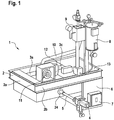
- FIG. 1 a modularly constructed spinning beam 1 is shown, which has a peripheral frame 2 on which all the essential components are arranged or attached.
- the frame 2 is formed from a circumferential U or double T-beam into which a modular assembly 20a (FIG. FIG. 2 ) can be suspended or used.
- the frame 2 is rectangular in construction and has two narrow sides 2a and two longitudinal sides 2b.
- openings 23a, 23b, 23c are arranged for spin packs to be inserted, which can be closed by covers 3a, 3b, 3c and insulation, which are arranged on the frame 2.
- a drive 4 is arranged for a pump 24, wherein the drive 4 with the pump 24 via a shaft 5 is connectable.
- the pump 24 is arranged lying and transversely or orthogonal to the longitudinal side of the spinner 1 and promotes the liquid plastic through the nozzles of the spin packs.
- the drive 4 can be arranged outside the frame 2 on a scaffold, which accommodates the modularly constructed spinning beam 1.
- a boiler 25 is arranged, the For example, absorbs Diphyl as a heating medium.
- openings 26 are arranged on the boiler, in the heating elements can be inserted. Outwardly, both the boiler 25 and the openings 26 for the heating elements are each closed by a cover 6, 7.
- a vacuum station 8 is mounted with a condenser 9, which are connected via a pipe 10 to a heat chamber 27a.
- the heat chamber 27a corresponds to at least one further heat chamber 27b, so that the spinnerets are enclosed at least from two sides, whereby a circulating circulation of the heating medium between the vacuum station 8, the heat chambers 27a, 27b and the boiler 25 is formed.
- Both the condenser 9 and the vacuum station 8 are attached with their ancillaries on the spinning beam 1.
- a heat transfer medium for example Diphyl, is placed inside the boiler 25 by the heating elements in a vaporous state, so that the steam flows through the heat chambers 27a, 27b.
- a condensate occurring within the heat cycle is returned via condensate lines to the vacuum station 8 and to the condenser 9.
- FIG. 1 further shows a flange connection 11 for a pipeline, via which liquid plastic is conveyed to the pump 24 from an externally arranged extruder.
- the flange 11 is also attached to the spinning beam 1 and connected by means of pipes 12 to the pump 24 and the spinnerets.
- the spinning beam 1 has a walk-on surface, under which an insulation 13 is arranged.
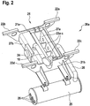
- the modular assembly 20a after FIG. 2 essentially comprises a suspension 21, which has at least two transverse beams 21a, 21b, between which the heat chambers 27a, 27b and the openings 23a, 23b, 23c are arranged for the spin packs with the spinnerets.
- the spinning beam 1 is designed for three spin packs, each with a spinneret, since each opening 23a, 23b, 23c can receive a spin pack.
- the spinning beam 1 can also be designed only for a spinning package, two spin packages, or for more than three spin packages. In the longitudinal direction of the spinning beam 1 so the spin packs are arranged one behind the other to produce a variable number of spinning lines.
- the heat chambers 27a, 27b are an integral part of the suspension 21 and connect the cross members 21a, 21b with each other, so that a self-supporting modular assembly 20a is formed within the spinner 1.
- the heat chambers 27a, 27b are connected to one another in the region of the cross members 21a, 21b in such a way that the spin packages are evenly heated on two further sides, the end faces.
- pads 22a - 22d are arranged, with which the modular assembly 20a in the frame 2 or in a framework can be suspended.
- the boiler 25 is arranged lying on the cross member 21b.
- angle profiles are arranged on an end face on the cross member 21a, 21b, in which the boiler 25 is adjustably mounted in the embodiment.
- the boiler 25 is placed horizontally so that the openings 26 for the heating rods are accessible without further disassembly from a gangway of a scaffold.
- the boiler 25 is arranged transversely or orthogonally to a longitudinal side 2b of the frame 2 or to the longitudinal side 2b of the spinning beam 1.
- Another pipeline 10 leads the heat transfer medium from the heat chamber 27b to the condenser 9.
- the modular assembly 20a thus includes the suspension 21, which is connected by the two transverse beams 21a, 21b with the heat chambers 27a, 27b arranged therebetween.
- the heat chamber 27a is connected via a pipe 28 to the boiler 25, which is also part of the modular assembly 20a.
- Another component of the modular assembly 20a is the pump 24, on or in the area of Heat chamber 27b is arranged horizontally and supplies all integrated within the assembly spinnerets with extruded plastic, as well as the pipe 10.
- the cross member 21a, 21b further have pads 22a - 22d, where the modular assembly 20a in the frame 2 or in a frame can be suspended and attachable.
- the liquid plastic is passed to the pump 24 via the flange connection 11 and from there via further pipelines to the spinnerets. It is advantageous that all pipelines which conduct liquid plastic to the spinnerets are arranged to fall, so that a backflow of the liquid melt to the extruder or to the pump 24 during the exchange of components is avoided.
- mixers can be integrated at one or more points, which mix the molten plastic.
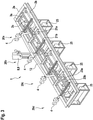
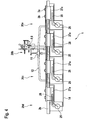
- each modular assembly 20a - 20d is suspended with two cross members 21a, 21b in the frame 2, wherein the pads 22a - 22d on a profile rest of the frame 2 and are connected to this.
- Each modular subassembly 20a-20d in this exemplary embodiment, can accommodate two spin packs each having a spinneret which can be inserted into the openings 23a, 23b and closed by the covers 3a, 3b. Under the covers 3a, 3b, the spin packs can be insulated by insertable heat blocks upwards, which have a circumferential seal to avoid a chimney effect within the opening 23a, 23b.
- the spin packs are arranged in parallel between the longitudinal sides 2b of the frame 2.
- a vacuum station 8 and a condenser 9 are connected for the heat cycle of all modules with all boilers 25 via pipes, from each boiler 25, a pipe 28, the heat transfer medium to the heat chambers 27a directs.
- the boilers 25 are connected to each other via a pipe 14, so that the same heat cycle results for each modular assembly 20a - 20d even with multiple arrangement.
- All spinning packages are supplied with liquid plastic from an external extruder via a single flange connection 11.
- a pipe 12 is arranged, which, starting from the flange connection 11, directs the liquid plastic to the pumps 24.
- the front side of the spinning beam 1, in the area of which the drives 4 are arranged, is easily accessible to the operating personnel for the maintenance of the pumps 24, so that the heating elements in the boilers 25 can also be changed from this side.
- the boiler 25 are arranged horizontally and transversely or orthogonal to the longitudinal side 2b of the frame 2. Due to the fact that the pump 24 is also arranged lying horizontally or orthogonally to the longitudinal side of the spinning beam 1, the entire spinning beam 1 can be maintained from one position. Both measures, namely the horizontal arrangement of the boiler 25 and the pump 24 transversely or orthogonal to the longitudinal side of the frame 2 allows a more compact design of the spinner 1, since no space requirement between the spinning packages or between the modules is required for the maintenance of both components. This takes place exclusively at the operating passage of the scaffold, which has enough space for changing the long heating rods and the pumps 24.
Landscapes
- Engineering & Computer Science (AREA)
- Mechanical Engineering (AREA)
- Textile Engineering (AREA)
- Spinning Methods And Devices For Manufacturing Artificial Fibers (AREA)
Description
- Die Erfindung betrifft einen Spinnbalken zur Herstellung von schmelzgesponnenen Filamenten nach dem Oberbegriff von Anspruch 1.
- Die bekannten Spinnbalken weisen Spinndüsenpakete auf, die reihenförmig an der Unterseite des Spinnbalkens angeordnet sind. Je nach Größe der Anlage werden mehrere Spinnbalkenmodule fest nebeneinander angeordnet, die über Rohrleitungen für das Wärmeträgermedium fest miteinander verbunden sind. Der hohe Platzbedarf der nebeneinander angeordneten Spinnbalkenmodule ist von der Montagesituation der Heizstäbe und Pumpe abhängig, die nur unter großem Aufwand gewartet und ggf. getauscht werden können, da hierfür ausreichend Platz zwischen den Spinnbalkenmodulen vorhanden sein muss. Eine Anpassung an eine vergrößerte Anlagenkapazität ist nur mit großem Aufwand möglich.
- Die
EP 2122019 B1 offenbart eine Vorrichtung zum Schmelzspinnen synthetischer Elemente, bei dem die Spinnpumpe an einem separaten Pumpenträger angeordnet ist, der beabstandet vom Gehäuse des Spinnbalkens angeordnet ist. Es ergibt sich ein sehr großer Abstand zwischen der Pumpe und der Spinndüse, der mit dem technologischen Nachteil einer längeren Verweilzeit verbunden ist und aufgrund des Platzbedarfes eine mögliche Erweiterung der Anlage nur mit hohem Aufwand realisierbar macht. - Die
US 6,083,432 zeigt einen modular aufgebauten Spinnbalken, bei dem aufgrund der vertikalen Anordnung von Spinnpaket und Pumpe die einzelnen Komponenten nur schwer zugänglich sind. Jeder Spinnbalken kann nur mit einem Spinnpaket ausgestattet werden, wobei der Boiler außerhalb der modularen Baugruppe angeordnet ist. - In der
US 3,655,314 bildet eine wärmeleitende Platte einen tragenden Boden für die Aufnahme aller Komponenten des Spinnbalkens. Die Platte weist für die Aufnahme von Spinnpaketen Öffnungen auf. - Die
US 6,736,624 offenbart eine Stützkonstruktion, unterhalb der das Spinnpaket mit dem umschließenden Heizraum angeordnet ist. - Aufgabe der vorliegenden Erfindung ist es, die bekannten Spinnbalken konstruktiv zu vereinfachen, einen erleichterten Zugang zur Wartung der Pumpe zu ermöglichen bei gleichzeitig kompakter Bauweise.
- Die Aufgabe wird gelöst durch einen Spinnbalken zur Herstellung von schmelzgesponnenen Filamenten, bei dem über einen extern angeordneten Extruder flüssiger Kunststoff zu mindestens einer Pumpe gefördert wird, die den flüssigen Kunststoff zu mindestens einem Spinnpaket mit einer Spinndüse fördert, wobei zumindest die Pumpe und das Spinnpaket von einem Wärmeträgermedium beheizt werden, das in einem Boiler erhitzt wird.
- Die Erfindung ist dadurch gekennzeichnet, dass die Pumpe, der Boiler und eine Öffnung zur Aufnahme eines Spinnpaketes in einer modularen Baugruppe angeordnet sind, die einzeln oder mehrfach hintereinander in einen Rahmen eines Spinnbalkens einsetzbar und befestigbar ist.
- Der Spinnbalken lässt sich damit beliebig um weitere Spinnpakete erweitern, wodurch die Anlagenkapazität sehr leicht einer steigenden Produktion angepasst werden kann.
- Dabei weist die modulare Baugruppe eine Aufhängung auf, die mindestens zwei Querträger umfasst. Die Querträger sind so dimensioniert, dass sie in den Rahmen des Spinnbalkens einsetzbar sind. An den Querträgern erfolgt der gesamte Aufbau der modularen Baugruppe.
- Zu einer weiteren Verbesserung dient, dass die Querträger mit mindestens einer Wärmekammer derart verbunden sind, dass eine Öffnung zur Aufnahme mindestens eines Spinnpaketes gebildet wird. Die Querträger und die Wärmekammer bilden damit einen Rahmen, in dem die Öffnungen zur Aufnahme der Spinnpakete angeordnet sind. Die Verbindung der Querträger mit den Wärmekammern ergibt einen tragenden Rahmen, an dem alle anderen Bauteile der modularen Baugruppe befestigbar sind
- Bevorzugt ist die Pumpe liegend und quer bzw. orthogonal zu einer Längsseite des Rahmens angeordnet. Damit kann die Pumpe von einem Betriebsgang des Gerüstes aus gewartet werden, ohne dass große Demontagearbeiten erforderlich sind.
- Eine weitere Verbesserung wird dadurch erreicht, dass der Boiler liegend und quer bzw. orthogonal zu einer Längsseite des Rahmens angeordnet ist. Beide Maßnahmen, nämlich die liegende Anordnung des Boilers und der Pumpe orthogonal zur Längsseite des Rahmens ermöglicht eine kompaktere Bauweise des Spinnbalkens, da für die Wartung beider Bauteile kein Platzbedarf zwischen den Spinnpaketen bzw. zwischen den Baugruppen erforderlich ist. Dies erfolgt ausschließlich am Bediengang des Gerüstes, der genug Platz für das Wechseln der langen Heizstäbe und der Pumpen aufweist. Insbesondere durch diese Anordnung des Boilers wird der Platzbedarf für die einzelnen Baugruppen verringert, wodurch mit einer geringeren Teilung auch die Leitungen für den flüssigen Kunststoff kürzer ausgelegt werden können. Die seitliche Anordnung des Boilers ermöglicht auch einen guten Zugang zur Pumpe und zur Monomerabsaugung. Der verfügbare Platz zwischen den Blasschächten wird für den Boiler genutzt, so dass keine zusätzliche Standfläche für einen separat stehenden Boiler auf der Stahlplattform erforderlich ist. Die Anordnung des Boilers ermöglicht eine geringe Teilung, da die Heizstäbe etwa 90° zur Spinnbalkenachse liegen.
- Die Pumpe und der Boiler müssen nicht exakt rechtwinklig zum Längsträger angeordnet sein. Auch eine leicht schräge Anordnung von beispielsweise 75° der Längsachse des Boilers und der Pumpe zum Längsträger, bei dem die Komponenten, beispielsweise die Heizstäbe, über den Bediengang ausgetauscht werden können, würde unter den Begriff quer bzw. orthogonal fallen. Beim Stand der Technik sind die Pumpe und der Boiler zwischen den Spinnpaketen demontierbar angeordnet, so dass der Abstand zwischen den Spinnpaketen durch den Demontageplatz der austauschbaren Komponenten bestimmt wird. Nach dieser Erfindung kann die Anordnung der Spinnbalken in einem sehr dichten Abstand zueinander erfolgen, was die Gesamtanlage kompakter macht und die Schmelze führenden Leitungen verkürzt, was den verfahrenstechnischen Vorteil der kürzeren Verweilzeit für den flüssigen Kunststoff bedeutet.
- Bevorzugt wird die Pumpe mittels einer Welle von einem Antrieb angetrieben, wobei der Antrieb an einem Gerüst außerhalb des Spinnbalkens angeordnet ist. Durch die Demontage der Welle wird die Pumpe sehr leicht zugänglich und kann durch Lösen weniger Schrauben leicht demontiert werden.
- Durch die Anordnung mehrerer modularer Baugruppen zu einem Spinnbalken, werden alle Boiler mittels Rohrleitungen mit einer Vakuumstation und einem Kondensor verbunden. Insbesondere dadurch, dass die Boiler mittels einer Rohrleitung miteinander verbunden sind, entsteht ein System kommunizierender Röhren, wodurch für jede modulare Baugruppe eine identische Heizsituation entsteht.
- Eine weitere Verbesserung wird dadurch erreicht, indem der flüssige Kunststoff über einen Flanschanschluss mittels mindestens einer Rohrleitung zu den Pumpen geleitet wird, wobei die Rohrleitungen fallend angeordnet sind. Damit können sich keine Ablagerungen von flüssigem Kunststoff unterschiedlicher Viskosität bilden. Die Ausführung ermöglicht im Unterschied zum Stand der Technik kurze Schmelzeleitungen mit entsprechend kurzen Verweilzeiten für den flüssigen Kunststoff.
- Die Erfindung wird anhand der beiliegenden Zeichnungen näher erläutert. In diesen zeigen
- Fig.1:
- eine perspektivische Darstellung auf einen modular aufgebauten Spinnbalken;
- Fig. 2:
- eine perspektivische Darstellung auf den inneren Aufbau eines Spinnbalkens;
- Fig. 3:
- eine perspektivische Darstellung auf einen Spinnbalken mit mehreren nebeneinander angeordneten modularen Baugruppen;
- Fig. 4:
- eine Seitenansicht auf einen Spinnbalken mit mehreren nebeneinander angeordneten modularen Baugruppen.
- In
Figur 1 ist ein modular aufgebauter Spinnbalken 1 dargestellt, der einen umlaufenden Rahmen 2 aufweist, an dem alle wesentlichen Komponenten angeordnet bzw. befestigt sind. Der Rahmen 2 ist aus einem umlaufenden U- oder Doppel-T-Träger gebildet, in den eine modulare Baugruppe 20a (Figur 2 ) einhängbar bzw. einsetzbar ist. Der Rahmen 2 ist rechteckig aufgebaut und weist zwei Schmalseiten 2a und zwei Längsseiten 2b auf. Innerhalb der modularen Baugruppe 20a sind Öffnungen 23a, 23b, 23c für einzusetzende Spinnpakete angeordnet, die durch Abdeckungen 3a, 3b, 3c und Isolierungen, die am Rahmen 2 angeordnet sind, verschließbar sind. Außerhalb des Spinnbalkens 1 ist ein Antrieb 4 für eine Pumpe 24 angeordnet, wobei der Antrieb 4 mit der Pumpe 24 über eine Welle 5 verbindbar ist. Die Pumpe 24 ist liegend und quer bzw. orthogonal zur Längsseite des Spinnbalkens 1 angeordnet und fördert den flüssigen Kunststoff durch die Düsen der Spinnpakete. Der Antrieb 4 kann außerhalb des Rahmens 2 an einem Gerüst angeordnet sein, das den modular aufgebauten Spinnbalken 1 aufnimmt. Ebenfalls innerhalb des Spinnbalkens 1 ist ein Boiler 25 angeordnet, der beispielsweise Diphyl als Heizmedium aufnimmt. Zur Erwärmung des Wärmeträgermediums sind an dem Boiler 25 Öffnungen 26 angeordnet, in die Heizstäbe einschiebbar sind. Nach außen hin sind sowohl der Boiler 25 wie auch die Öffnungen 26 für die Heizstäbe durch jeweils eine Abdeckung 6, 7 verschlossen. Oberhalb des Spinnbalken 1 ist eine Vakuumstation 8 mit einem Kondensor 9 montiert, die über eine Rohrleitung 10 mit einer Wärmekammer 27a verbunden sind. Die Wärmekammer 27a korrespondiert mit mindestens einer weiteren Wärmekammer 27b, so dass die Spinndüsen mindestens von zwei Seiten umschlossen sind, wobei ein zirkulierender Kreislauf des Heizmediums zwischen der Vakuumstation 8, den Wärmekammern 27a, 27b und dem Boiler 25 entsteht. Sowohl der Kondensor 9 wie auch die Vakuumstation 8 sind mit ihren Nebenaggregaten am Spinnbalken 1 befestigt. Ein Wärmeträgermedium, beispielsweise Diphyl, wird innerhalb des Boilers 25 durch die Heizstäbe in einen dampfförmigen Zustand versetzt, so dass der Dampf die Wärmekammern 27a, 27b durchströmt. Ein innerhalb des Wärmekreislaufes auftretendes Kondensat wird über Kondensatleitungen zur Vakuumstation 8 und zum Kondensor 9 zurück geführt. -
Figur 1 zeigt weiterhin einen Flanschanschluss 11 für eine Rohrleitung, über die von einem extern angeordneten Extruder flüssiger Kunststoff zur Pumpe 24 gefördert wird. Der Flanschanschluss 11 ist ebenfalls am Spinnbalken 1 befestigt und mittels Rohrleitungen 12 mit der Pumpe 24 und den Spinndüsen verbunden. Weiterhin weist der Spinnbalken 1 eine begehbare Oberfläche auf, unter der eine Isolierung 13 angeordnet ist. - Die modulare Baugruppe 20a nach
Figur 2 umfasst im Wesentlichen eine Aufhängung 21, die mindestens zwei Querträger 21a, 21b aufweist, zwischen denen die Wärmekammern 27a, 27b und die Öffnungen 23a, 23b, 23c für die Spinnpakete mit den Spinndüsen angeordnet sind. Es ist erkennbar, dass in diesem Ausführungsbeispiel der Spinnbalken 1 für drei Spinnpakete mit je einer Spinndüse ausgelegt ist, da jede Öffnung 23a, 23b, 23c ein Spinnpaket aufnehmen kann. Der Spinnbalken 1 kann aber auch nur für ein Spinnpaket, zwei Spinnpakete, oder für mehr als drei Spinnpakete konzipiert werden. In Längsrichtung des Spinnbalkens 1 sind also die Spinnpakete hintereinander angeordnet, um eine variable Anzahl von Spinnstreckanlagen zu erzeugen. Die Wärmekammern 27a, 27b sind integraler Bestandteil der Aufhängung 21 und verbinden die Querträger 21a, 21b miteinander, so dass eine selbsttragende modulare Baugruppe 20a innerhalb des Spinnbalkens 1 entsteht. Damit das Wärmeträgermedium zirkulieren kann, sind die Wärmekammern 27a, 27b im Bereich der Querträger 21a, 21b derart miteinander verbunden, dass die Spinnpakete auch an zwei weiteren Seiten, den Stirnseiten, gleichmäßig erwärmt werden. An den Querträgern 21a, 21b sind Auflagen 22a - 22d angeordnet, mit der die modulare Baugruppe 20a in den Rahmen 2 oder in ein Gerüst einhängbar ist. Auf der gegenüberliegenden Seite zu den Wärmekammern 27a, 27b ist am Querträger 21b der Boiler 25 liegend angeordnet. Hierzu sind in dem Ausführungsbeispiel Winkelprofile an einer Stirnseite an dem Querträgers 21a, 21b angeordnet, an denen der Boiler 25 einstellbar befestigt wird. Der Boiler 25 ist liegend so platziert, dass die Öffnungen 26 für die Heizstäbe ohne weitere Demontage von einem Gang eines Gerüstes zugänglich sind. Dazu ist der Boiler 25 quer bzw. orthogonal zu einer Längsseite 2b des Rahmens 2 bzw. zur Längsseite 2b des Spinnbalkens 1 angeordnet. Eine weitere Rohrleitung 10 führt das Wärmeträgermedium aus der Wärmekammer 27b zum Kondensor 9 ab. - Die modulare Baugruppe 20a umfasst damit die Aufhängung 21, die durch die zwei Querträger 21a, 21b mit den dazwischen angeordneten Wärmekammern 27a, 27b verbunden ist. Die Wärmekammer 27a ist über eine Rohrleitung 28 mit dem Boiler 25 verbunden, der ebenfalls Bestandteil der modularen Baugruppe 20a ist. Weiterer Bestandteil der modularen Baugruppe 20a ist die Pumpe 24, die an bzw. im Bereich der Wärmekammer 27b liegend angeordnet ist und alle innerhalb der Baugruppe integrierten Spinndüsen mit extrudiertem Kunststoff versorgt, sowie die Rohrleitung 10. Die Querträger 21a, 21b weisen weiterhin Auflagen 22a - 22d auf, an denen die modulare Baugruppe 20a in den Rahmen 2 oder in ein Gerüst einhängbar und befestigbar ist.
- Die Pumpe 24, die über eine Welle 5 mit dem Antrieb 4 verbunden ist, wird über die Rohrleitung 12 mit flüssigem Kunststoff von einem außerhalb des Spinnbalkens 1 angeordneten Extruder versorgt. Hierzu wird über den Flanschanschluss 11 der flüssige Kunststoff zur Pumpe 24 und von dieser über weitere Rohrleitungen zu den Spinndüsen geleitet. Von Vorteil ist, dass alle Rohrleitungen, die flüssigen Kunststoff zu den Spinndüsen leiten, fallend angeordnet sind, damit ein Zurückfließen der flüssigen Schmelze zum Extruder oder zur Pumpe 24 beim Austausch von Komponenten vermieden wird. Innerhalb der Rohrleitungen für flüssigen Kunststoff, beispielsweise der Rohrleitung 12, können an einer oder mehrerer Stellen Mischer integriert sein, die den geschmolzenen Kunststoff durchmischen.
- In dem Ausführungsbeispiel der
Figuren 3 und4 sind vier modulare Baugruppen 20a, 20b, 20c, 20d an einem Rahmen 2 angeordnet und bilden den Spinnbalken 1. Jede modulare Baugruppe 20a - 20d wird mit beiden Querträger 21a, 21b in den Rahmen 2 eingehängt, wobei die Auflagen 22a - 22d auf einem Profil des Rahmens 2 aufliegen und mit diesem verbunden sind. Jede modulare Baugruppe 20a - 20d kann in diesem Ausführungsbeispiel zwei Spinnpakete mit jeweils einer Spinndüse aufnehmen, die in die Öffnungen 23a, 23b einsetzbar und mit den Abdeckungen 3a, 3b verschließbar sind. Unter den Abdeckungen 3a, 3b können die Spinnpakete durch einsetzbare Wärmeblöcke nach oben isoliert werden, die eine umlaufende Dichtung aufweisen, um innerhalb der Öffnung 23a, 23b einen Kamineffekt zu vermeiden. Die Spinnpakete sind parallel zwischen den Längsseiten 2b des Rahmens 2 angeordnet. - Eine Vakuumstation 8 und ein Kondensor 9 sind für den Wärmekreislauf aller Baugruppen mit allen Boilern 25 über Rohrleitungen verbunden, wobei von jedem Boiler 25 eine Rohrleitung 28 das Wärmeträgermedium zu den Wärmekammern 27a leitet. Dabei sind die Boiler 25 über eine Rohrleitung 14 untereinander verbunden, so dass sich für jede modulare Baugruppe 20a - 20d auch bei Mehrfachanordnung der gleiche Wärmekreislauf ergibt. Über einen einzigen Flanschanschluss 11 werden alle Spinnpakete von einem externen Extruder mit flüssigem Kunststoff versorgt. Hierzu ist eine Rohrleitung 12 angeordnet, die ausgehend von dem Flanschanschluss 11 den flüssigen Kunststoff zu den Pumpen 24 leitet. Die Vorderseite des Spinnbalkens 1, in deren Bereich die Antriebe 4 angeordnet sind, ist für das Bedienungspersonal zur Wartung der Pumpen 24 leicht zugänglich, so dass von dieser Seite auch die Heizstäbe in den Boilern 25 gewechselt werden können. Dazu sind die Boiler 25 liegend und quer bzw. orthogonal zur Längsseite 2b des Rahmens 2 angeordnet. Dadurch, dass auch die Pumpe 24 liegend und quer bzw. orthogonal zur Längsseite des Spinnbalkens 1 angeordnet ist, kann der gesamte Spinnbalken 1 aus einer Position gewartet werden. Beide Maßnahmen, nämlich die liegende Anordnung des Boilers 25 und der Pumpe 24 quer bzw. orthogonal zur Längsseite des Rahmens 2 ermöglicht eine kompaktere Bauweise des Spinnbalkens 1, da für die Wartung beider Bauteile kein Platzbedarf zwischen den Spinnpaketen bzw. zwischen den Baugruppen erforderlich ist. Dies erfolgt ausschließlich am Bediengang des Gerüstes, der genug Platz für das Wechseln der langen Heizstäbe und der Pumpen 24 aufweist.
-
- 1
- Spinnbalken
- 2
- Rahmen
- 2a
- Schmalseite
- 2b
- Längsseite
- 3a-c
- Abdeckung
- 4
- Antrieb
- 5
- Welle
- 6
- Abdeckung
- 7
- Abdeckung
- 8
- Vakuumstation
- 9
- Kondensor
- 10
- Rohrleitung
- 11
- Flanschanschluss
- 12
- Rohrleitung
- 13
- Isolierung
- 14
- Rohrleitung
- 20a - 20d
- modulare Baugruppe
- 21
- Aufhängung
- 21a, b
- Querträger
- 22a - 22d
- Auflage
- 23a - 23c
- Öffnung
- 24
- Pumpe
- 25
- Boiler
- 26
- Öffnung
- 27a, b
- Wärmekammer
- 28
- Rohrleitung
Claims (7)
- Spinnbalken zur Herstellung von schmelzgesponnenen Filamenten, bei dem über einen extern angeordneten Extruder flüssiger Kunststoff zu mindestens einer Pumpe gefördert wird, die den flüssigen Kunststoff zu mindestens einem Spinnpaket mit einer Spinndüse fördert, wobei zumindest die Pumpe und das Spinnpaket von einem Wärmeträgermedium beheizt werden, das in einem Boiler erhitzt wird, dadurch gekennzeichnet, dass zumindest die Pumpe (24), der Boiler (25) und eine Öffnung (23) zur Aufnahme eines Spinnpaketes in einer modularen Baugruppe (20) angeordnet sind, die einzeln oder mehrfach hintereinander in einen Rahmen (2) eines Spinnbalkens (1) einsetzbar und befestigbar ist, wobei die modulare Baugruppe (20) eine Aufhängung (21) aufweist, die mindestens zwei Querträger (21a, 21b) umfasst, die mit mindestens einer Wärmekammer (27a, 27b) einen tragenden Rahmen bilden, in dem mindestens eine Öffnung (23) zur Aufnahme mindestens eines Spinnpaketes angeordnet ist.
- Spinnbalken nach Anspruch 1, dadurch gekennzeichnet, dass die Pumpe (24) liegend und quer bzw. orthogonal zu einer Längsseite (2b) des Rahmens (2) angeordnet ist.
- Spinnbalken nach Anspruch 1, dadurch gekennzeichnet, dass der Boiler (25) liegend und quer bzw. orthogonal zu einer Längsseite (2b) des Rahmens angeordnet ist.
- Spinnbalken nach einem der vorhergehenden Ansprüche, dadurch gekennzeichnet, dass die Pumpe (24) mittels einer Welle (5) von einem Antrieb (4) angetrieben wird, wobei der Antrieb (4) an einem Gerüst außerhalb des Spinnbalkens (1) angeordnet ist.
- Spinnbalken nach Anspruch 1, dadurch gekennzeichnet, dass mehrere modulare Baugruppen (20a, 20b, 20c, 20d) einen Spinnbalken bilden, wobei eine Vakuumstation (8) und ein Kondensor (9) mit allen Boilern (25) mittels Rohrleitungen verbunden sind.
- Spinnbalken nach Anspruch 1, dadurch gekennzeichnet, dass die Boiler (25) mittels einer Rohrleitung (14) miteinander verbunden sind.
- Spinnbalken nach einem der vorhergehenden Ansprüche, dadurch gekennzeichnet, dass der flüssige Kunststoff über einen Flanschanschluss (11) mittels mindestens einer Rohrleitung (12) zu den Pumpen (24) geleitet wird, wobei die Rohrleitungen fallend angeordnet sind.
Applications Claiming Priority (2)
| Application Number | Priority Date | Filing Date | Title |
|---|---|---|---|
| DE102015100179.9A DE102015100179A1 (de) | 2015-01-08 | 2015-01-08 | Spinnbalken zur Herstellung von schmelzgesponnenen Filamentgarnen |
| PCT/EP2015/002301 WO2016110300A1 (de) | 2015-01-08 | 2015-11-18 | Spinnbalken zur herstellung von schmelzgesponnenen filamenten |
Publications (2)
| Publication Number | Publication Date |
|---|---|
| EP3242966A1 EP3242966A1 (de) | 2017-11-15 |
| EP3242966B1 true EP3242966B1 (de) | 2018-10-24 |
Family
ID=54601731
Family Applications (1)
| Application Number | Title | Priority Date | Filing Date |
|---|---|---|---|
| EP15797257.1A Active EP3242966B1 (de) | 2015-01-08 | 2015-11-18 | Spinnbalken zur herstellung von schmelzgesponnenen filamenten |
Country Status (7)
| Country | Link |
|---|---|
| US (1) | US10662551B2 (de) |
| EP (1) | EP3242966B1 (de) |
| KR (1) | KR101919271B1 (de) |
| CN (1) | CN107109702B (de) |
| DE (1) | DE102015100179A1 (de) |
| TR (1) | TR201820046T4 (de) |
| WO (1) | WO2016110300A1 (de) |
Families Citing this family (2)
| Publication number | Priority date | Publication date | Assignee | Title |
|---|---|---|---|---|
| CN114427123B (zh) * | 2022-01-27 | 2023-04-25 | 九江中科鑫星新材料有限公司 | 一种超高分子量聚乙烯纤维生产用保温机构 |
| EP4365339A1 (de) | 2022-11-02 | 2024-05-08 | Trützschler Group SE | Spinnbalken zur herstellung von schmelzgesponnenen filamenten oder garnen |
Family Cites Families (17)
| Publication number | Priority date | Publication date | Assignee | Title |
|---|---|---|---|---|
| DE1908207B2 (de) * | 1969-02-19 | 1973-10-18 | Barmag Barmer Maschinenfabrik Ag, 5600 Wuppertal | Beheizbarer Spinnbalken zum Erzeugen von Endlosfäden aus synthetischen Polymeren |
| SU643556A1 (ru) * | 1970-08-06 | 1979-01-25 | Феб Пласт Унд Эластферарбайтунгсмашиненкомбинат (Инопредприятие) | Устройство дл формировани полотна синтетических нитей |
| DE9313586U1 (de) | 1993-09-08 | 1993-11-04 | Synthetik Fiber Machinery, 63762 Großostheim | Spinnbalken |
| CN2216070Y (zh) * | 1994-12-30 | 1995-12-27 | 侯慕毅 | 模块组合式宽体喷丝机头 |
| US5618566A (en) * | 1995-04-26 | 1997-04-08 | Exxon Chemical Patents, Inc. | Modular meltblowing die |
| CN2277999Y (zh) * | 1996-08-20 | 1998-04-08 | 大连合成纤维研究所 | 整体易拆卸式纺丝箱 |
| KR19980024331A (ko) | 1996-09-04 | 1998-07-06 | 핑슈텐 | 방사 빔 |
| EP0828017B1 (de) | 1996-09-04 | 2001-11-28 | B a r m a g AG | Spinnbalken |
| US5866050A (en) * | 1997-02-06 | 1999-02-02 | E. I. Du Pont De Nemours And Company | Method and spinning apparatus having a multiple-temperature control arrangement therein |
| DE19924838A1 (de) * | 1999-05-29 | 2000-11-30 | Lurgi Zimmer Ag | Spinnvorrichtung zum Verspinnen schmelzflüssiger Polymere und Verfahren zum Beheizen der Spinnvorrichtung |
| DE10116959A1 (de) | 2001-04-05 | 2002-10-10 | Neumag Gmbh & Co Kg | Vorrichtung zum Schmelzspinnen und Ablegen mehrerer Spinnkabel |
| DE10258261A1 (de) * | 2002-12-13 | 2004-06-24 | Saurer Gmbh & Co. Kg | Spinnbalken |
| DE10355542A1 (de) * | 2003-11-27 | 2005-06-23 | Saurer Gmbh & Co. Kg | Spinnanlage |
| CN101437991B (zh) * | 2006-05-08 | 2010-12-29 | 欧瑞康纺织有限及两合公司 | 用于熔融纺造、处理和卷绕合成长丝的设备 |
| EP2122019B1 (de) | 2007-02-24 | 2010-11-24 | Oerlikon Textile GmbH & Co. KG | Vorrichtung zum schmelzspinnen synthetischer filamente |
| CN101550611B (zh) * | 2007-06-12 | 2010-12-08 | 东华大学 | 纺粘生产的模块式纺丝箱体 |
| CN201801640U (zh) * | 2010-08-13 | 2011-04-20 | 胡尹烟 | 组合式喷丝板 |
-
2015
- 2015-01-08 DE DE102015100179.9A patent/DE102015100179A1/de not_active Withdrawn
- 2015-11-18 EP EP15797257.1A patent/EP3242966B1/de active Active
- 2015-11-18 CN CN201580071267.2A patent/CN107109702B/zh active Active
- 2015-11-18 TR TR2018/20046T patent/TR201820046T4/tr unknown
- 2015-11-18 WO PCT/EP2015/002301 patent/WO2016110300A1/de not_active Ceased
- 2015-11-18 KR KR1020177022068A patent/KR101919271B1/ko active Active
- 2015-11-18 US US15/542,406 patent/US10662551B2/en active Active
Non-Patent Citations (1)
| Title |
|---|
| None * |
Also Published As
| Publication number | Publication date |
|---|---|
| WO2016110300A1 (de) | 2016-07-14 |
| DE102015100179A1 (de) | 2016-07-14 |
| US20170350039A1 (en) | 2017-12-07 |
| CN107109702A (zh) | 2017-08-29 |
| EP3242966A1 (de) | 2017-11-15 |
| KR20170126451A (ko) | 2017-11-17 |
| CN107109702B (zh) | 2019-07-26 |
| KR101919271B1 (ko) | 2018-11-15 |
| US10662551B2 (en) | 2020-05-26 |
| TR201820046T4 (tr) | 2019-01-21 |
Similar Documents
| Publication | Publication Date | Title |
|---|---|---|
| EP0497296B1 (de) | Filter-Ventilator-Einrichtung zur Verwendung bei Reinräumen | |
| EP0122464A2 (de) | Spinnkopf zum Schmelzspinnen endloser Fäden | |
| EP3242966B1 (de) | Spinnbalken zur herstellung von schmelzgesponnenen filamenten | |
| EP0436105B1 (de) | Spinneinrichtung | |
| DE102015012846A1 (de) | Schmelzspinnvorrichtung | |
| EP2505742B1 (de) | Kühlturm | |
| DE1508564B1 (de) | Verfahren und Einrichtung zum Kuehlen von Granulat insbesondere Kalkgranulat | |
| EP2760657B1 (de) | Haltevorrichtung für ein extrudergehäuse | |
| DE102015102312A1 (de) | Rohrbündelwärmeübertrager mit sequentiell angeordneten Rohrbündelkomponenten | |
| DE4002739C1 (en) | Appts. for cooling oil in hydraulic drive unit - includes two coaxial guide tubes for oils, cooling tube in annular chamber filter insert etc. | |
| EP1129625B1 (de) | Kühltunnel für Süsswarenstücke | |
| DE19643699C1 (de) | Schachtkühler | |
| DE102004028918B4 (de) | Vorrichtung zum Spinnen von Fäden | |
| EP1126227A1 (de) | Dampfkondensator | |
| EP2069703B1 (de) | Wärmetauscher | |
| DE102010052208A1 (de) | Extruder mit einem längsgeteilten Gehäuse | |
| DE2506146A1 (de) | Universalmaschine zum herstellen von einkristallen | |
| DE102014102562B4 (de) | Presse, Fertigungsanlage und Verfahren zur Herstellung eines faserverstärkten Werkstoffes sowie Heizplatte einer Presse | |
| DE2120600B2 (de) | Schmelzspinnvorrichtung | |
| DE4220952C2 (de) | Wirbelschichtreaktor zum Kühlen oder Erhitzen körniger Feststoffe durch indirekten Wärmeaustausch | |
| EP4365339A1 (de) | Spinnbalken zur herstellung von schmelzgesponnenen filamenten oder garnen | |
| DE102004007147B4 (de) | Streckwerk für Spinnmaschinen | |
| DE2460642C3 (de) | Vorrichtung zum Schmelzspinnen eines faserbildenden synthetischen Polymers | |
| WO1998017959A1 (de) | Schachtkühler | |
| DE1508564C (de) |
Legal Events
| Date | Code | Title | Description |
|---|---|---|---|
| PUAI | Public reference made under article 153(3) epc to a published international application that has entered the european phase |
Free format text: ORIGINAL CODE: 0009012 |
|
| 17P | Request for examination filed |
Effective date: 20170808 |
|
| AK | Designated contracting states |
Kind code of ref document: A1 Designated state(s): AL AT BE BG CH CY CZ DE DK EE ES FI FR GB GR HR HU IE IS IT LI LT LU LV MC MK MT NL NO PL PT RO RS SE SI SK SM TR |
|
| AX | Request for extension of the european patent |
Extension state: BA ME |
|
| DAV | Request for validation of the european patent (deleted) | ||
| DAX | Request for extension of the european patent (deleted) | ||
| REG | Reference to a national code |
Ref country code: DE Ref legal event code: R079 Ref document number: 502015006615 Country of ref document: DE Free format text: PREVIOUS MAIN CLASS: D01D0004000000 Ipc: D01D0001060000 |
|
| RIC1 | Information provided on ipc code assigned before grant |
Ipc: D01D 4/06 20060101ALI20180509BHEP Ipc: D01D 5/08 20060101ALI20180509BHEP Ipc: D01D 4/00 20060101ALI20180509BHEP Ipc: D01D 1/06 20060101AFI20180509BHEP |
|
| GRAP | Despatch of communication of intention to grant a patent |
Free format text: ORIGINAL CODE: EPIDOSNIGR1 |
|
| INTG | Intention to grant announced |
Effective date: 20180626 |
|
| GRAS | Grant fee paid |
Free format text: ORIGINAL CODE: EPIDOSNIGR3 |
|
| GRAA | (expected) grant |
Free format text: ORIGINAL CODE: 0009210 |
|
| AK | Designated contracting states |
Kind code of ref document: B1 Designated state(s): AL AT BE BG CH CY CZ DE DK EE ES FI FR GB GR HR HU IE IS IT LI LT LU LV MC MK MT NL NO PL PT RO RS SE SI SK SM TR |
|
| REG | Reference to a national code |
Ref country code: CH Ref legal event code: EP |
|
| REG | Reference to a national code |
Ref country code: IE Ref legal event code: FG4D Free format text: LANGUAGE OF EP DOCUMENT: GERMAN |
|
| REG | Reference to a national code |
Ref country code: AT Ref legal event code: REF Ref document number: 1056776 Country of ref document: AT Kind code of ref document: T Effective date: 20181115 |
|
| REG | Reference to a national code |
Ref country code: DE Ref legal event code: R096 Ref document number: 502015006615 Country of ref document: DE |
|
| REG | Reference to a national code |
Ref country code: CH Ref legal event code: NV Representative=s name: BOHEST AG, CH |
|
| REG | Reference to a national code |
Ref country code: NL Ref legal event code: MP Effective date: 20181024 |
|
| REG | Reference to a national code |
Ref country code: LT Ref legal event code: MG4D |
|
| PG25 | Lapsed in a contracting state [announced via postgrant information from national office to epo] |
Ref country code: NL Free format text: LAPSE BECAUSE OF FAILURE TO SUBMIT A TRANSLATION OF THE DESCRIPTION OR TO PAY THE FEE WITHIN THE PRESCRIBED TIME-LIMIT Effective date: 20181024 |
|
| PG25 | Lapsed in a contracting state [announced via postgrant information from national office to epo] |
Ref country code: ES Free format text: LAPSE BECAUSE OF FAILURE TO SUBMIT A TRANSLATION OF THE DESCRIPTION OR TO PAY THE FEE WITHIN THE PRESCRIBED TIME-LIMIT Effective date: 20181024 Ref country code: HR Free format text: LAPSE BECAUSE OF FAILURE TO SUBMIT A TRANSLATION OF THE DESCRIPTION OR TO PAY THE FEE WITHIN THE PRESCRIBED TIME-LIMIT Effective date: 20181024 Ref country code: LV Free format text: LAPSE BECAUSE OF FAILURE TO SUBMIT A TRANSLATION OF THE DESCRIPTION OR TO PAY THE FEE WITHIN THE PRESCRIBED TIME-LIMIT Effective date: 20181024 Ref country code: BG Free format text: LAPSE BECAUSE OF FAILURE TO SUBMIT A TRANSLATION OF THE DESCRIPTION OR TO PAY THE FEE WITHIN THE PRESCRIBED TIME-LIMIT Effective date: 20190124 Ref country code: PL Free format text: LAPSE BECAUSE OF FAILURE TO SUBMIT A TRANSLATION OF THE DESCRIPTION OR TO PAY THE FEE WITHIN THE PRESCRIBED TIME-LIMIT Effective date: 20181024 Ref country code: FI Free format text: LAPSE BECAUSE OF FAILURE TO SUBMIT A TRANSLATION OF THE DESCRIPTION OR TO PAY THE FEE WITHIN THE PRESCRIBED TIME-LIMIT Effective date: 20181024 Ref country code: LT Free format text: LAPSE BECAUSE OF FAILURE TO SUBMIT A TRANSLATION OF THE DESCRIPTION OR TO PAY THE FEE WITHIN THE PRESCRIBED TIME-LIMIT Effective date: 20181024 Ref country code: IS Free format text: LAPSE BECAUSE OF FAILURE TO SUBMIT A TRANSLATION OF THE DESCRIPTION OR TO PAY THE FEE WITHIN THE PRESCRIBED TIME-LIMIT Effective date: 20190224 Ref country code: NO Free format text: LAPSE BECAUSE OF FAILURE TO SUBMIT A TRANSLATION OF THE DESCRIPTION OR TO PAY THE FEE WITHIN THE PRESCRIBED TIME-LIMIT Effective date: 20190124 |
|
| PG25 | Lapsed in a contracting state [announced via postgrant information from national office to epo] |
Ref country code: SE Free format text: LAPSE BECAUSE OF FAILURE TO SUBMIT A TRANSLATION OF THE DESCRIPTION OR TO PAY THE FEE WITHIN THE PRESCRIBED TIME-LIMIT Effective date: 20181024 Ref country code: RS Free format text: LAPSE BECAUSE OF FAILURE TO SUBMIT A TRANSLATION OF THE DESCRIPTION OR TO PAY THE FEE WITHIN THE PRESCRIBED TIME-LIMIT Effective date: 20181024 Ref country code: PT Free format text: LAPSE BECAUSE OF FAILURE TO SUBMIT A TRANSLATION OF THE DESCRIPTION OR TO PAY THE FEE WITHIN THE PRESCRIBED TIME-LIMIT Effective date: 20190224 Ref country code: GR Free format text: LAPSE BECAUSE OF FAILURE TO SUBMIT A TRANSLATION OF THE DESCRIPTION OR TO PAY THE FEE WITHIN THE PRESCRIBED TIME-LIMIT Effective date: 20190125 Ref country code: AL Free format text: LAPSE BECAUSE OF FAILURE TO SUBMIT A TRANSLATION OF THE DESCRIPTION OR TO PAY THE FEE WITHIN THE PRESCRIBED TIME-LIMIT Effective date: 20181024 |
|
| REG | Reference to a national code |
Ref country code: DE Ref legal event code: R097 Ref document number: 502015006615 Country of ref document: DE |
|
| PG25 | Lapsed in a contracting state [announced via postgrant information from national office to epo] |
Ref country code: DK Free format text: LAPSE BECAUSE OF FAILURE TO SUBMIT A TRANSLATION OF THE DESCRIPTION OR TO PAY THE FEE WITHIN THE PRESCRIBED TIME-LIMIT Effective date: 20181024 Ref country code: LU Free format text: LAPSE BECAUSE OF NON-PAYMENT OF DUE FEES Effective date: 20181118 Ref country code: CZ Free format text: LAPSE BECAUSE OF FAILURE TO SUBMIT A TRANSLATION OF THE DESCRIPTION OR TO PAY THE FEE WITHIN THE PRESCRIBED TIME-LIMIT Effective date: 20181024 |
|
| REG | Reference to a national code |
Ref country code: IE Ref legal event code: MM4A |
|
| PG25 | Lapsed in a contracting state [announced via postgrant information from national office to epo] |
Ref country code: SM Free format text: LAPSE BECAUSE OF FAILURE TO SUBMIT A TRANSLATION OF THE DESCRIPTION OR TO PAY THE FEE WITHIN THE PRESCRIBED TIME-LIMIT Effective date: 20181024 Ref country code: SK Free format text: LAPSE BECAUSE OF FAILURE TO SUBMIT A TRANSLATION OF THE DESCRIPTION OR TO PAY THE FEE WITHIN THE PRESCRIBED TIME-LIMIT Effective date: 20181024 Ref country code: MC Free format text: LAPSE BECAUSE OF FAILURE TO SUBMIT A TRANSLATION OF THE DESCRIPTION OR TO PAY THE FEE WITHIN THE PRESCRIBED TIME-LIMIT Effective date: 20181024 Ref country code: EE Free format text: LAPSE BECAUSE OF FAILURE TO SUBMIT A TRANSLATION OF THE DESCRIPTION OR TO PAY THE FEE WITHIN THE PRESCRIBED TIME-LIMIT Effective date: 20181024 Ref country code: RO Free format text: LAPSE BECAUSE OF FAILURE TO SUBMIT A TRANSLATION OF THE DESCRIPTION OR TO PAY THE FEE WITHIN THE PRESCRIBED TIME-LIMIT Effective date: 20181024 |
|
| PLBE | No opposition filed within time limit |
Free format text: ORIGINAL CODE: 0009261 |
|
| STAA | Information on the status of an ep patent application or granted ep patent |
Free format text: STATUS: NO OPPOSITION FILED WITHIN TIME LIMIT |
|
| 26N | No opposition filed |
Effective date: 20190725 |
|
| PG25 | Lapsed in a contracting state [announced via postgrant information from national office to epo] |
Ref country code: FR Free format text: LAPSE BECAUSE OF NON-PAYMENT OF DUE FEES Effective date: 20181224 Ref country code: SI Free format text: LAPSE BECAUSE OF FAILURE TO SUBMIT A TRANSLATION OF THE DESCRIPTION OR TO PAY THE FEE WITHIN THE PRESCRIBED TIME-LIMIT Effective date: 20181024 Ref country code: IE Free format text: LAPSE BECAUSE OF NON-PAYMENT OF DUE FEES Effective date: 20181118 |
|
| PG25 | Lapsed in a contracting state [announced via postgrant information from national office to epo] |
Ref country code: MT Free format text: LAPSE BECAUSE OF FAILURE TO SUBMIT A TRANSLATION OF THE DESCRIPTION OR TO PAY THE FEE WITHIN THE PRESCRIBED TIME-LIMIT Effective date: 20181024 |
|
| PG25 | Lapsed in a contracting state [announced via postgrant information from national office to epo] |
Ref country code: HU Free format text: LAPSE BECAUSE OF FAILURE TO SUBMIT A TRANSLATION OF THE DESCRIPTION OR TO PAY THE FEE WITHIN THE PRESCRIBED TIME-LIMIT; INVALID AB INITIO Effective date: 20151118 Ref country code: CY Free format text: LAPSE BECAUSE OF FAILURE TO SUBMIT A TRANSLATION OF THE DESCRIPTION OR TO PAY THE FEE WITHIN THE PRESCRIBED TIME-LIMIT Effective date: 20181024 Ref country code: MK Free format text: LAPSE BECAUSE OF NON-PAYMENT OF DUE FEES Effective date: 20181024 |
|
| GBPC | Gb: european patent ceased through non-payment of renewal fee |
Effective date: 20191118 |
|
| PG25 | Lapsed in a contracting state [announced via postgrant information from national office to epo] |
Ref country code: GB Free format text: LAPSE BECAUSE OF NON-PAYMENT OF DUE FEES Effective date: 20191118 |
|
| REG | Reference to a national code |
Ref country code: AT Ref legal event code: PC Ref document number: 1056776 Country of ref document: AT Kind code of ref document: T Owner name: TRUETZSCHLER GROUP SE, DE Effective date: 20220516 |
|
| REG | Reference to a national code |
Ref country code: DE Ref legal event code: R081 Ref document number: 502015006615 Country of ref document: DE Owner name: TRUETZSCHLER GROUP SE, DE Free format text: FORMER OWNER: TRUETZSCHLER GMBH & CO. KG, 41199 MOENCHENGLADBACH, DE |
|
| REG | Reference to a national code |
Ref country code: BE Ref legal event code: PD Owner name: TRUETZSCHLER GROUP SE; DE Free format text: DETAILS ASSIGNMENT: CHANGE OF OWNER(S), MERGE; FORMER OWNER NAME: TRUETZSCHLER GMBH & CO. KG Effective date: 20220330 |
|
| P01 | Opt-out of the competence of the unified patent court (upc) registered |
Effective date: 20230622 |
|
| PGFP | Annual fee paid to national office [announced via postgrant information from national office to epo] |
Ref country code: DE Payment date: 20241121 Year of fee payment: 10 |
|
| PGFP | Annual fee paid to national office [announced via postgrant information from national office to epo] |
Ref country code: BE Payment date: 20241120 Year of fee payment: 10 |
|
| PGFP | Annual fee paid to national office [announced via postgrant information from national office to epo] |
Ref country code: AT Payment date: 20241121 Year of fee payment: 10 |
|
| PGFP | Annual fee paid to national office [announced via postgrant information from national office to epo] |
Ref country code: IT Payment date: 20241126 Year of fee payment: 10 |
|
| PGFP | Annual fee paid to national office [announced via postgrant information from national office to epo] |
Ref country code: CH Payment date: 20241201 Year of fee payment: 10 |
|
| PGFP | Annual fee paid to national office [announced via postgrant information from national office to epo] |
Ref country code: TR Payment date: 20251111 Year of fee payment: 11 |