EP3242985B1 - Motorschloss - Google Patents
Motorschloss Download PDFInfo
- Publication number
- EP3242985B1 EP3242985B1 EP15797296.9A EP15797296A EP3242985B1 EP 3242985 B1 EP3242985 B1 EP 3242985B1 EP 15797296 A EP15797296 A EP 15797296A EP 3242985 B1 EP3242985 B1 EP 3242985B1
- Authority
- EP
- European Patent Office
- Prior art keywords
- clutch
- lock according
- actuator
- motor lock
- motor
- Prior art date
- Legal status (The legal status is an assumption and is not a legal conclusion. Google has not performed a legal analysis and makes no representation as to the accuracy of the status listed.)
- Active
Links
Images
Classifications
-
- E—FIXED CONSTRUCTIONS
- E05—LOCKS; KEYS; WINDOW OR DOOR FITTINGS; SAFES
- E05B—LOCKS; ACCESSORIES THEREFOR; HANDCUFFS
- E05B47/00—Operating or controlling locks or other fastening devices by electric or magnetic means
- E05B47/0001—Operating or controlling locks or other fastening devices by electric or magnetic means with electric actuators; Constructional features thereof
- E05B47/0012—Operating or controlling locks or other fastening devices by electric or magnetic means with electric actuators; Constructional features thereof with rotary electromotors
-
- E—FIXED CONSTRUCTIONS
- E05—LOCKS; KEYS; WINDOW OR DOOR FITTINGS; SAFES
- E05B—LOCKS; ACCESSORIES THEREFOR; HANDCUFFS
- E05B47/00—Operating or controlling locks or other fastening devices by electric or magnetic means
- E05B47/02—Movement of the bolt by electromagnetic means; Adaptation of locks, latches, or parts thereof, for movement of the bolt by electromagnetic means
- E05B47/026—Movement of the bolt by electromagnetic means; Adaptation of locks, latches, or parts thereof, for movement of the bolt by electromagnetic means the bolt moving rectilinearly
-
- E—FIXED CONSTRUCTIONS
- E05—LOCKS; KEYS; WINDOW OR DOOR FITTINGS; SAFES
- E05B—LOCKS; ACCESSORIES THEREFOR; HANDCUFFS
- E05B63/00—Locks or fastenings with special structural characteristics
- E05B63/0065—Operating modes; Transformable to different operating modes
-
- E—FIXED CONSTRUCTIONS
- E05—LOCKS; KEYS; WINDOW OR DOOR FITTINGS; SAFES
- E05B—LOCKS; ACCESSORIES THEREFOR; HANDCUFFS
- E05B65/00—Locks or fastenings for special use
- E05B65/10—Locks or fastenings for special use for panic or emergency doors
-
- E—FIXED CONSTRUCTIONS
- E05—LOCKS; KEYS; WINDOW OR DOOR FITTINGS; SAFES
- E05B—LOCKS; ACCESSORIES THEREFOR; HANDCUFFS
- E05B47/00—Operating or controlling locks or other fastening devices by electric or magnetic means
- E05B47/0001—Operating or controlling locks or other fastening devices by electric or magnetic means with electric actuators; Constructional features thereof
- E05B2047/0014—Constructional features of actuators or power transmissions therefor
- E05B2047/0018—Details of actuator transmissions
- E05B2047/0026—Clutches, couplings or braking arrangements
- E05B2047/0028—Clutches, couplings or braking arrangements using electromagnetic means
-
- E—FIXED CONSTRUCTIONS
- E05—LOCKS; KEYS; WINDOW OR DOOR FITTINGS; SAFES
- E05B—LOCKS; ACCESSORIES THEREFOR; HANDCUFFS
- E05B47/00—Operating or controlling locks or other fastening devices by electric or magnetic means
- E05B47/0001—Operating or controlling locks or other fastening devices by electric or magnetic means with electric actuators; Constructional features thereof
- E05B2047/0014—Constructional features of actuators or power transmissions therefor
- E05B2047/0037—Powered actuators with automatic return to the neutral position by non-powered means, e.g. springs
Definitions
- the invention relates to a motor lock, in particular for a fire door, with a bolt and a couplable with this electric motor.
- the additional power supply typically includes accumulators, capacitors, or a combination thereof, which takes up a relatively large amount of space.
- the invention has for its object to provide a motor lock of the type mentioned, in which the risk that the lock is not locked in an emergency, with the least possible effort further minimized.
- the motor lock provided in particular for a fire door comprises a latch and an electric motor which can be coupled thereto.
- the engine lock is designed so that the bolt in its open position acted upon by a biased spring unit in its closed position and the engine via a clutch with the Bar is coupled, which is kept closed via an actuator, as long as the actuator is powered and released in the event of a power failure of the actuator.
- the lock Due to this training, the risk that the lock no longer automatically locked in an emergency, with relatively little effort is reduced to a minimum.
- the previously required usually additional power supply can be omitted.
- the spring unit in question is triggered automatically in case of power failure, so that even with a separation of the supply line or an active interruption of the power supply through the fire protection system, the lock can still be reliably locked.
- the clutch is closed by the actuator to couple the latch to the engine. In the event of a power failure, the clutch is released by the actuator. With the opening clutch, the bolt is disconnected from the engine and the preloaded spring unit triggered, after which the bolt is transferred by this spring unit in its closed position. In this case, the preloaded spring unit can contract or expand with the opening of the clutch.
- the electric motor can be coupled via a self-locking gear with a bolt mechanism comprising the bolt and the clutch is arranged so that the motor can be separated from the bolt mechanism by releasing the clutch by releasing the self-locking of the gearbox.
- the clutch can be arranged in particular in the transmission.
- the locking mechanism may include in addition to the bolt in particular different gears and a shift gate, over which the bolt is displaceable.
- the clutch comprises two axially relative to each other adjustable gears, which are compressible against the force of a spring unit on the actuator for producing a rotationally fixed connection between the two gears and in case of failure of the power supply can be released by the actuator to to be separated from each other by the spring unit by canceling the rotationally fixed connection.
- one of the two gears may be provided, for example, as a pinion of the relevant gear pair.
- this compression spring may in particular have a conical shape.
- the two gears of the clutch form-fitting or non-positively connected to each other.
- the tooth edges are axially separated and the coupling is opened accordingly.
- the two gears of the coupling via at least one, preferably detachably connectable to each other via a plurality of pins.
- a respective pin is firmly anchored on the one hand in one of the two gears and on the other hand with the compression of the two gears in an opening provided in the other gear opening inserted.
- the two gears of the clutch When energized activated actuator, the two gears of the clutch are thus connected via the pins form-fitting or rotationally fixed to each other.
- the two gears are released in case of failure of the power supply from the actuator and axially separated from each other by the spring unit associated with the coupling, whereby each fixed in one of the two gears pins are released from the other gear and the clutch is opened accordingly.
- the two gears of the clutch can be compressed by a coupling claw connected to the actuator against the force of the spring unit acting on the clutch in the opening direction.
- one of the two gears of the clutch axially fixed in the lock housing and the other gear is relatively axially displaceable and the axially displaceable gear can be acted upon by the coupling claw.
- the coupling claw is held by the powered actuator against the force of a biased spring unit in the position in which the two gears of the clutch are compressed, while the clutch claw in case of failure of the power supply through the biased spring unit in a release position is movable, in which it releases the axially displaceable gear of the clutch.
- the coupling claw is held in the position in which it compresses the two gears of the clutch between the axially displaceable gear of the clutch and a beveled projection of the lock housing, whereby it is pressed against the relevant gear ,
- the coupling claw is preferably provided with a bend or bulge, in which the projection of the lock housing is received when the coupling claw assumes its release position.
- the coupling claw is preferably hingedly connected to a linearly movable armature of the actuator.
- the actuator may in particular comprise an electromagnet, a piezoelement and / or the like.
- the locking mechanism may in particular comprise a shift gate, via which the bolt can be acted upon.
- One of the two gears of the clutch in particular the axially fixed in the lock housing gear, in particular can be in operative connection with a driven by the electric motor worm.
- the other gear of the clutch may in particular be operatively connected to a first gear of the transmission of the latch mechanism of the engine lock.
- a bolt or the like may be arranged, via which the shift gate is displaceable in order to adjust the bolt.
- the shift gate can be acted upon by a prestressed spring unit in the closed position.
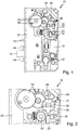
- Fig. 1 to 7 show a schematic representation of an exemplary embodiment of a motor lock 10 according to the invention, which can be used in particular in a fire door.
- the motor lock 12 comprises a latch 12, at least one latch 14 and an auxiliary latch 16.
- the motor lock 10 comprises an electric motor 18 which can be coupled to the latch 12.
- the latch 12 is acted upon in its open position by a preloaded spring unit in its closed position.
- the electric motor 18 can be coupled via a coupling 20 with the latch 12.
- the clutch 20 is closed via an actuator 22, as long as the actuator 22 is supplied with power. In case of power failure, the clutch 20 is released by the actuator 22 and opens. If the clutch 20 is open, the self-locking of the transmission is released and the latch 12 is transferred to the closed position.
- the electric motor 18 via a self-locking gear with a bolt 12 comprehensive latch mechanism can be coupled, which also includes a shift gate 24, via which the bolt 12 is movable.
- the clutch 20 is arranged so that with an opening of the clutch 20 of the electric motor 18 can be separated by canceling the self-locking of the transmission of the latch mechanism.
- the clutch 20 may be arranged for example in the transmission, and the locking mechanism may be provided except the latch 12 and the shift gate 24 with different gears.
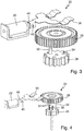
- the clutch 20 comprises two axially relative to each other adjustable gears 26, 28, via the actuator 22 for producing a rotationally fixed connection between the two gears 26, 28 against the force of a spring unit 30 (see Fig. 4 . 5 and 7 ) are compressible and can be released in case of failure of the power supply by the actuator 22 to be separated from each other by the spring unit 30 by canceling the rotationally fixed connection.
- a spring unit 30 between the two gears 26, 28 of the clutch 20, for example, at least one, in particular in a recess of one of the two gears 26, 28 seated compression spring can be arranged.
- the spring unit 30 is formed by such a compression spring.
- the compression spring may for example have a conical shape.
- the two gears 26, 28 of the coupling 20 can be positively or non-positively connectable, in particular via at least one, preferably via a plurality of pins 32, the gears 26, 28 of the clutch 20 can be releasably connected to each other.
- a respective pin 32 in particular one hand in one of the two gears 26, 28 firmly anchored and on the other hand with the compression of the two gears 26, 28 in an opening provided in the other gear 34 be inserted.
- the two toothed wheels 26, 28 of the coupling 20 can be compressed by a coupling claw 36 connected to the actuator 22 against the force of the spring unit 30 acting on the coupling 20 in the opening direction.
- one of the two gears 26, 28 of the clutch 20 axially fixed in the lock housing 38 and the other gear can be axially displaceable relative thereto, wherein the axially displaceable gear can be acted upon by the coupling claw 36.
- the gear 26 is axially fixed in the lock housing 38 and the gear 28 relative to this axially displaceable and acted upon by the coupling claw 36.
- the coupling claw 36 is held by the powered actuator 22 against the force of another biased spring unit in the position in which the two gears 26, 28 of the clutch 20 are compressed.
- the coupling jaw 36 is movable in a power failure of the biased further spring unit in a release position in which it releases the axially displaceable gear 28 of the clutch 20. With the release of the axially displaceable gear 28, this gear 28 is axially separated from the other axially fixed in the lock housing 38 gear 26 by the coupling 20 in the opening direction acting spring unit, whereby the clutch 20 is opened.
- the coupling pawl 36 in the position in which it compresses the two gears 26, 28 of the clutch 20, ie in the present case the axially displaceable gear 28 presses against the axially fixed gear 26, between the axially displaceable gear 28 of Clutch 20 and provided with a slope 40 projection 42 of the lock housing 38 is held, whereby it is pressed against the axially displaceable gear 28.
- the projection 42 may be provided, for example, on a housing cover.
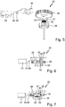
- the coupling claw 36 is provided with a bend or bulge 44, in which the projection 42 of the lock housing 38 is received when the coupling claw 36 assumes its release position (see. Fig. 7 ).
- the coupling claw 36 is in the present case, for example, hingedly connected to a linearly movable armature 46 of the actuator 22.
- the armature 46 is further extended by the (not shown) preloaded spring unit (see. Fig. 7 ), whereby the bend or bulge 44 of the coupling claw 36 comes in the region of the projection 42, after which the coupling claw 36 is pivoted relative to the armature 46 about the axis 48 to receive the projection in the bend or bulge 44, so the axially displaceable gearwheel 28 can be separated from the axially fixed gearwheel 26 by the spring unit 30.
- the clutch 20 is opened with it.
- the actuator may comprise, for example, an electromagnet, a piezoelectric element and / or the like.
- One of the two gears 26, 28 of the clutch 20 may be in operative connection with a driven by the electric motor 18 screw, in the present case, the axially fixed in the lock housing 38 gear 26 is operatively connected to the screw.
- the two gears 26, 28, for example, three pins 32 are releasably connected together, in the present case, two pins 32 are firmly anchored in the axially displaceable gear 28 and a pin in the axially fixed gear 26 is firmly anchored.
- Fig. 1 shows the engine lock 10 in a schematic side view, wherein the housing cover is removed.
- a lock cylinder 52 a particular provided with a door handle nut 54 and different gears 56 of the latch mechanism can be seen.
- a bolt 58 or the like may be arranged, which shifts the shift gate 24 and thus the bolt 12 of the motor lock 10 moves accordingly.
- Fig. 2 shows a part of the engine lock 10 again in an enlarged side view.
- Fig. 3 the clutch 2 and the actuator 22 are shown in an enlarged perspective, exploded view.
- Fig. 4 shows one with Fig. 3 Comparable perspective, exploded view of the clutch 20 and the actuator 22, wherein in the present case, the provided between the gears 26, 28 of the clutch 20 spring unit 30 can be seen.
- Fig. 5 shows one with the Fig. 4 Comparable perspective, exploded view of the clutch 20 and the actuator 22 from a different angle.
- Fig. 6 shows the closed coupling 20 with associated actuator 22 in a schematic side view.
- Fig. 7 shows the opened clutch 20 with associated currentless actuator 22 reproduced.
- the spring unit 30 may comprise at least one compression spring, which may for example sit in a recess of one of the two gears 26, 28, which may be formed for example by a recess or pocket in the relevant gear.
- a compression spring can be conically shaped in particular.
- One of the two gears 26, 28, in particular the gear 26 fixed axially in the motor housing 38, can be driven by a worm 60 driven by the electric motor 18 (cf. Fig. 1 and 2 ) are in operative connection.
- the locking mechanism With the opening of the clutch 20, the locking mechanism is then separated from the electric motor 18 with associated worm 60, whereupon the bolt 12 is transferred by the latch 12 acting in the closing direction biased spring unit in its closed position, since the self-locking of the transmission is canceled.
Landscapes
- Business, Economics & Management (AREA)
- Emergency Management (AREA)
- Engineering & Computer Science (AREA)
- Structural Engineering (AREA)
- Physics & Mathematics (AREA)
- Electromagnetism (AREA)
- Lock And Its Accessories (AREA)
- Connection Of Motors, Electrical Generators, Mechanical Devices, And The Like (AREA)
Priority Applications (1)
| Application Number | Priority Date | Filing Date | Title |
|---|---|---|---|
| PL15797296T PL3242985T3 (pl) | 2015-01-08 | 2015-11-17 | Zamek elektryczny |
Applications Claiming Priority (2)
| Application Number | Priority Date | Filing Date | Title |
|---|---|---|---|
| DE102015200117.2A DE102015200117B9 (de) | 2015-01-08 | 2015-01-08 | Motorschloss |
| PCT/EP2015/076826 WO2016110355A1 (de) | 2015-01-08 | 2015-11-17 | Motorschloss |
Publications (2)
| Publication Number | Publication Date |
|---|---|
| EP3242985A1 EP3242985A1 (de) | 2017-11-15 |
| EP3242985B1 true EP3242985B1 (de) | 2018-10-31 |
Family
ID=54601762
Family Applications (1)
| Application Number | Title | Priority Date | Filing Date |
|---|---|---|---|
| EP15797296.9A Active EP3242985B1 (de) | 2015-01-08 | 2015-11-17 | Motorschloss |
Country Status (6)
| Country | Link |
|---|---|
| EP (1) | EP3242985B1 (pl) |
| CN (1) | CN107223174B (pl) |
| DE (1) | DE102015200117B9 (pl) |
| ES (1) | ES2707980T3 (pl) |
| PL (1) | PL3242985T3 (pl) |
| WO (1) | WO2016110355A1 (pl) |
Families Citing this family (4)
| Publication number | Priority date | Publication date | Assignee | Title |
|---|---|---|---|---|
| DE102017100739B3 (de) | 2017-01-16 | 2018-06-28 | Aquis Sanitär AG | Schlüsselbetätigungsvorrichtung |
| DE102017126490A1 (de) | 2017-11-10 | 2019-05-16 | Hörmann KG Antriebstechnik | Türschlossantriebsvorrichtung, Türschlossvorrichtung und damit ausgestattete Tür |
| DE102020132139A1 (de) * | 2020-12-03 | 2022-06-09 | Kiekert Aktiengesellschaft | Zuzieheinrichtung für ein Kraftfahrzeug-Schloss |
| CN115110868A (zh) * | 2021-03-17 | 2022-09-27 | 江苏二十六度节能科技研究院有限公司 | 一种用于智能窗的自动锁窗系统 |
Family Cites Families (8)
| Publication number | Priority date | Publication date | Assignee | Title |
|---|---|---|---|---|
| FI79168C (fi) | 1985-12-05 | 1991-03-26 | Waertsilae Oy Ab | Doerrlaos. |
| CN2542779Y (zh) * | 2002-04-30 | 2003-04-02 | 叶春财 | 电动辅助锁 |
| KR100517437B1 (ko) * | 2003-02-10 | 2005-09-29 | 유규식 | 방화문 자동 폐쇄장치 |
| FI120109B (fi) * | 2006-05-02 | 2009-06-30 | Abloy Oy | Lukkorunko |
| CN201169988Y (zh) * | 2008-01-16 | 2008-12-24 | 洪晓君 | 一种常开防火门电控锁 |
| DE202010006954U1 (de) | 2010-05-11 | 2010-08-05 | Bks Gmbh | Schließvorrichtung mit motorischer Antriebseinrichtung |
| DE102011051952B4 (de) | 2011-07-19 | 2021-03-25 | Mehmet Sancak | Fernaktivierbares selbstverriegelndes Türschloss |
| EP2679750A1 (en) | 2012-06-26 | 2014-01-01 | 9Design.be bvba | Locking device comprising a deactivation mechanism |
-
2015
- 2015-01-08 DE DE102015200117.2A patent/DE102015200117B9/de not_active Withdrawn - After Issue
- 2015-11-17 PL PL15797296T patent/PL3242985T3/pl unknown
- 2015-11-17 EP EP15797296.9A patent/EP3242985B1/de active Active
- 2015-11-17 CN CN201580076237.0A patent/CN107223174B/zh not_active Expired - Fee Related
- 2015-11-17 WO PCT/EP2015/076826 patent/WO2016110355A1/de not_active Ceased
- 2015-11-17 ES ES15797296T patent/ES2707980T3/es active Active
Non-Patent Citations (1)
| Title |
|---|
| None * |
Also Published As
| Publication number | Publication date |
|---|---|
| PL3242985T3 (pl) | 2019-04-30 |
| EP3242985A1 (de) | 2017-11-15 |
| CN107223174A (zh) | 2017-09-29 |
| WO2016110355A1 (de) | 2016-07-14 |
| DE102015200117B4 (de) | 2018-08-09 |
| DE102015200117A1 (de) | 2016-07-14 |
| ES2707980T3 (es) | 2019-04-08 |
| CN107223174B (zh) | 2019-08-13 |
| DE102015200117B9 (de) | 2018-10-25 |
Similar Documents
| Publication | Publication Date | Title |
|---|---|---|
| DE102014019837B3 (de) | Linearaktor | |
| EP2713797B1 (de) | Schnallenanordnung | |
| DE102007059744A1 (de) | Getriebebaueinheit einer Verstelleinrichtung eines Kraftfahrzeugs | |
| DE102007045177A1 (de) | Verriegelungsvorrichtung | |
| DE102007061055A1 (de) | Klappenanordnung | |
| EP3038859B1 (de) | Teleskopierbare vorrichtung | |
| DE102015200117B9 (de) | Motorschloss | |
| EP3565979A1 (de) | Befestigungsanordnung und ein entsprechendes schaltschrankgehäuse | |
| EP3269904B1 (de) | Kupplungssystem für ein schloss | |
| DE102011000961A1 (de) | Schweißdrahtfördervorrichtung | |
| DE102012111881A1 (de) | Motorisch betreibbares Standflügelschloss mit Riegel- und Fallenauswerfer | |
| DE102017100731A1 (de) | Entriegelungsvorrichtung zum Öffnen einer Tür mit einem Panikschloss, insbesondere ein Touchbar, mit einem Antrieb zum automatischen Öffnen des Panikschlosses | |
| EP2733286A2 (de) | Schwenkhebelverschluss mit geringer Einbautiefe | |
| EP1911428B1 (de) | Motorische Antriebsvorrichtung zum Antreiben eines Beförderungsmittels | |
| EP1681414A2 (de) | Verriegelungsvorrichtung | |
| DE102013113117B4 (de) | Hubvorrichtung für das Dach eines Nutzfahrzeugaufbaus | |
| DE102007012208A1 (de) | Vorrichtung zur Arretierung eines schwenkbaren Bauteiles eines Kraftfahrzeuges | |
| DE202010011972U1 (de) | Einrichtung zum Sichern der Schließstellung eines beweglich an einem Möbelrahmen angeordneten Schließelementes | |
| EP3287577B1 (de) | Schliessvorrichtung für eine tür, ein fenster oder dergleichen | |
| DE102008010465A1 (de) | Verriegelungsbolzen mit Schlüssel | |
| DE202013100828U1 (de) | Vorrichtung zum Befestigen eines Fahrzeugkennzeichens | |
| EP3725992A1 (de) | Antrieb | |
| DE19640227B4 (de) | Selbsthemmender elektromechanischer Torantrieb | |
| DE20307840U1 (de) | Notentriegelungsvorrichtung an einer Schwenkschiebetür für Fahrzeuge, insbesondere Fahrzeuge des öffentlichen Personennahverkehrs | |
| EP2213887A1 (de) | Verbindungsvorrichtung |
Legal Events
| Date | Code | Title | Description |
|---|---|---|---|
| PUAI | Public reference made under article 153(3) epc to a published international application that has entered the european phase |
Free format text: ORIGINAL CODE: 0009012 |
|
| 17P | Request for examination filed |
Effective date: 20170706 |
|
| AK | Designated contracting states |
Kind code of ref document: A1 Designated state(s): AL AT BE BG CH CY CZ DE DK EE ES FI FR GB GR HR HU IE IS IT LI LT LU LV MC MK MT NL NO PL PT RO RS SE SI SK SM TR |
|
| AX | Request for extension of the european patent |
Extension state: BA ME |
|
| DAV | Request for validation of the european patent (deleted) | ||
| DAX | Request for extension of the european patent (deleted) | ||
| GRAP | Despatch of communication of intention to grant a patent |
Free format text: ORIGINAL CODE: EPIDOSNIGR1 |
|
| INTG | Intention to grant announced |
Effective date: 20180605 |
|
| GRAS | Grant fee paid |
Free format text: ORIGINAL CODE: EPIDOSNIGR3 |
|
| GRAA | (expected) grant |
Free format text: ORIGINAL CODE: 0009210 |
|
| AK | Designated contracting states |
Kind code of ref document: B1 Designated state(s): AL AT BE BG CH CY CZ DE DK EE ES FI FR GB GR HR HU IE IS IT LI LT LU LV MC MK MT NL NO PL PT RO RS SE SI SK SM TR |
|
| REG | Reference to a national code |
Ref country code: CH Ref legal event code: EP Ref country code: GB Ref legal event code: FG4D Free format text: NOT ENGLISH |
|
| REG | Reference to a national code |
Ref country code: AT Ref legal event code: REF Ref document number: 1059583 Country of ref document: AT Kind code of ref document: T Effective date: 20181115 |
|
| REG | Reference to a national code |
Ref country code: IE Ref legal event code: FG4D Free format text: LANGUAGE OF EP DOCUMENT: GERMAN |
|
| REG | Reference to a national code |
Ref country code: DE Ref legal event code: R096 Ref document number: 502015006707 Country of ref document: DE |
|
| REG | Reference to a national code |
Ref country code: SE Ref legal event code: TRGR |
|
| REG | Reference to a national code |
Ref country code: NL Ref legal event code: FP |
|
| REG | Reference to a national code |
Ref country code: LT Ref legal event code: MG4D |
|
| REG | Reference to a national code |
Ref country code: EE Ref legal event code: FG4A Ref document number: E016832 Country of ref document: EE Effective date: 20190115 |
|
| REG | Reference to a national code |
Ref country code: ES Ref legal event code: FG2A Ref document number: 2707980 Country of ref document: ES Kind code of ref document: T3 Effective date: 20190408 |
|
| REG | Reference to a national code |
Ref country code: NO Ref legal event code: T2 Effective date: 20181031 |
|
| PG25 | Lapsed in a contracting state [announced via postgrant information from national office to epo] |
Ref country code: LV Free format text: LAPSE BECAUSE OF FAILURE TO SUBMIT A TRANSLATION OF THE DESCRIPTION OR TO PAY THE FEE WITHIN THE PRESCRIBED TIME-LIMIT Effective date: 20181031 Ref country code: IS Free format text: LAPSE BECAUSE OF FAILURE TO SUBMIT A TRANSLATION OF THE DESCRIPTION OR TO PAY THE FEE WITHIN THE PRESCRIBED TIME-LIMIT Effective date: 20190228 Ref country code: LT Free format text: LAPSE BECAUSE OF FAILURE TO SUBMIT A TRANSLATION OF THE DESCRIPTION OR TO PAY THE FEE WITHIN THE PRESCRIBED TIME-LIMIT Effective date: 20181031 Ref country code: BG Free format text: LAPSE BECAUSE OF FAILURE TO SUBMIT A TRANSLATION OF THE DESCRIPTION OR TO PAY THE FEE WITHIN THE PRESCRIBED TIME-LIMIT Effective date: 20190131 Ref country code: HR Free format text: LAPSE BECAUSE OF FAILURE TO SUBMIT A TRANSLATION OF THE DESCRIPTION OR TO PAY THE FEE WITHIN THE PRESCRIBED TIME-LIMIT Effective date: 20181031 |
|
| PG25 | Lapsed in a contracting state [announced via postgrant information from national office to epo] |
Ref country code: RS Free format text: LAPSE BECAUSE OF FAILURE TO SUBMIT A TRANSLATION OF THE DESCRIPTION OR TO PAY THE FEE WITHIN THE PRESCRIBED TIME-LIMIT Effective date: 20181031 Ref country code: PT Free format text: LAPSE BECAUSE OF FAILURE TO SUBMIT A TRANSLATION OF THE DESCRIPTION OR TO PAY THE FEE WITHIN THE PRESCRIBED TIME-LIMIT Effective date: 20190301 Ref country code: AL Free format text: LAPSE BECAUSE OF FAILURE TO SUBMIT A TRANSLATION OF THE DESCRIPTION OR TO PAY THE FEE WITHIN THE PRESCRIBED TIME-LIMIT Effective date: 20181031 Ref country code: GR Free format text: LAPSE BECAUSE OF FAILURE TO SUBMIT A TRANSLATION OF THE DESCRIPTION OR TO PAY THE FEE WITHIN THE PRESCRIBED TIME-LIMIT Effective date: 20190201 |
|
| REG | Reference to a national code |
Ref country code: SK Ref legal event code: T3 Ref document number: E 29968 Country of ref document: SK |
|
| PG25 | Lapsed in a contracting state [announced via postgrant information from national office to epo] |
Ref country code: DK Free format text: LAPSE BECAUSE OF FAILURE TO SUBMIT A TRANSLATION OF THE DESCRIPTION OR TO PAY THE FEE WITHIN THE PRESCRIBED TIME-LIMIT Effective date: 20181031 Ref country code: CZ Free format text: LAPSE BECAUSE OF FAILURE TO SUBMIT A TRANSLATION OF THE DESCRIPTION OR TO PAY THE FEE WITHIN THE PRESCRIBED TIME-LIMIT Effective date: 20181031 |
|
| REG | Reference to a national code |
Ref country code: DE Ref legal event code: R097 Ref document number: 502015006707 Country of ref document: DE |
|
| REG | Reference to a national code |
Ref country code: IE Ref legal event code: MM4A |
|
| PG25 | Lapsed in a contracting state [announced via postgrant information from national office to epo] |
Ref country code: MC Free format text: LAPSE BECAUSE OF FAILURE TO SUBMIT A TRANSLATION OF THE DESCRIPTION OR TO PAY THE FEE WITHIN THE PRESCRIBED TIME-LIMIT Effective date: 20181031 Ref country code: SM Free format text: LAPSE BECAUSE OF FAILURE TO SUBMIT A TRANSLATION OF THE DESCRIPTION OR TO PAY THE FEE WITHIN THE PRESCRIBED TIME-LIMIT Effective date: 20181031 Ref country code: RO Free format text: LAPSE BECAUSE OF FAILURE TO SUBMIT A TRANSLATION OF THE DESCRIPTION OR TO PAY THE FEE WITHIN THE PRESCRIBED TIME-LIMIT Effective date: 20181031 |
|
| PLBE | No opposition filed within time limit |
Free format text: ORIGINAL CODE: 0009261 |
|
| STAA | Information on the status of an ep patent application or granted ep patent |
Free format text: STATUS: NO OPPOSITION FILED WITHIN TIME LIMIT |
|
| 26N | No opposition filed |
Effective date: 20190801 |
|
| PG25 | Lapsed in a contracting state [announced via postgrant information from national office to epo] |
Ref country code: SI Free format text: LAPSE BECAUSE OF FAILURE TO SUBMIT A TRANSLATION OF THE DESCRIPTION OR TO PAY THE FEE WITHIN THE PRESCRIBED TIME-LIMIT Effective date: 20181031 Ref country code: IE Free format text: LAPSE BECAUSE OF NON-PAYMENT OF DUE FEES Effective date: 20181117 |
|
| PG25 | Lapsed in a contracting state [announced via postgrant information from national office to epo] |
Ref country code: MT Free format text: LAPSE BECAUSE OF FAILURE TO SUBMIT A TRANSLATION OF THE DESCRIPTION OR TO PAY THE FEE WITHIN THE PRESCRIBED TIME-LIMIT Effective date: 20181031 |
|
| PG25 | Lapsed in a contracting state [announced via postgrant information from national office to epo] |
Ref country code: TR Free format text: LAPSE BECAUSE OF FAILURE TO SUBMIT A TRANSLATION OF THE DESCRIPTION OR TO PAY THE FEE WITHIN THE PRESCRIBED TIME-LIMIT Effective date: 20181031 |
|
| PG25 | Lapsed in a contracting state [announced via postgrant information from national office to epo] |
Ref country code: CY Free format text: LAPSE BECAUSE OF FAILURE TO SUBMIT A TRANSLATION OF THE DESCRIPTION OR TO PAY THE FEE WITHIN THE PRESCRIBED TIME-LIMIT Effective date: 20181031 Ref country code: HU Free format text: LAPSE BECAUSE OF FAILURE TO SUBMIT A TRANSLATION OF THE DESCRIPTION OR TO PAY THE FEE WITHIN THE PRESCRIBED TIME-LIMIT; INVALID AB INITIO Effective date: 20151117 Ref country code: MK Free format text: LAPSE BECAUSE OF NON-PAYMENT OF DUE FEES Effective date: 20181031 |
|
| PGFP | Annual fee paid to national office [announced via postgrant information from national office to epo] |
Ref country code: NL Payment date: 20231120 Year of fee payment: 9 Ref country code: LU Payment date: 20231120 Year of fee payment: 9 |
|
| PGFP | Annual fee paid to national office [announced via postgrant information from national office to epo] |
Ref country code: SK Payment date: 20231113 Year of fee payment: 9 |
|
| PGFP | Annual fee paid to national office [announced via postgrant information from national office to epo] |
Ref country code: GB Payment date: 20231123 Year of fee payment: 9 |
|
| PGFP | Annual fee paid to national office [announced via postgrant information from national office to epo] |
Ref country code: NO Payment date: 20231124 Year of fee payment: 9 Ref country code: IT Payment date: 20231124 Year of fee payment: 9 Ref country code: EE Payment date: 20231117 Year of fee payment: 9 |
|
| PGFP | Annual fee paid to national office [announced via postgrant information from national office to epo] |
Ref country code: BE Payment date: 20231120 Year of fee payment: 9 |
|
| PGFP | Annual fee paid to national office [announced via postgrant information from national office to epo] |
Ref country code: ES Payment date: 20240129 Year of fee payment: 9 |
|
| P01 | Opt-out of the competence of the unified patent court (upc) registered |
Free format text: CASE NUMBER: UPC_APP_120126/2023 Effective date: 20230510 |
|
| REG | Reference to a national code |
Ref country code: EE Ref legal event code: MM4A Ref document number: E016832 Country of ref document: EE Effective date: 20241130 |
|
| REG | Reference to a national code |
Ref country code: SK Ref legal event code: MM4A Ref document number: E 29968 Country of ref document: SK Effective date: 20241117 |
|
| REG | Reference to a national code |
Ref country code: NL Ref legal event code: MM Effective date: 20241201 |
|
| PG25 | Lapsed in a contracting state [announced via postgrant information from national office to epo] |
Ref country code: NO Free format text: LAPSE BECAUSE OF NON-PAYMENT OF DUE FEES Effective date: 20241130 |
|
| PG25 | Lapsed in a contracting state [announced via postgrant information from national office to epo] |
Ref country code: LU Free format text: LAPSE BECAUSE OF NON-PAYMENT OF DUE FEES Effective date: 20241117 |
|
| PG25 | Lapsed in a contracting state [announced via postgrant information from national office to epo] |
Ref country code: EE Free format text: LAPSE BECAUSE OF NON-PAYMENT OF DUE FEES Effective date: 20241130 |
|
| GBPC | Gb: european patent ceased through non-payment of renewal fee |
Effective date: 20241117 |
|
| PG25 | Lapsed in a contracting state [announced via postgrant information from national office to epo] |
Ref country code: SK Free format text: LAPSE BECAUSE OF NON-PAYMENT OF DUE FEES Effective date: 20241117 |
|
| PG25 | Lapsed in a contracting state [announced via postgrant information from national office to epo] |
Ref country code: NL Free format text: LAPSE BECAUSE OF NON-PAYMENT OF DUE FEES Effective date: 20241201 |
|
| REG | Reference to a national code |
Ref country code: BE Ref legal event code: MM Effective date: 20241130 |
|
| PG25 | Lapsed in a contracting state [announced via postgrant information from national office to epo] |
Ref country code: IT Free format text: LAPSE BECAUSE OF NON-PAYMENT OF DUE FEES Effective date: 20241117 |
|
| PG25 | Lapsed in a contracting state [announced via postgrant information from national office to epo] |
Ref country code: BE Free format text: LAPSE BECAUSE OF NON-PAYMENT OF DUE FEES Effective date: 20241130 Ref country code: GB Free format text: LAPSE BECAUSE OF NON-PAYMENT OF DUE FEES Effective date: 20241117 |
|
| REG | Reference to a national code |
Ref country code: CH Ref legal event code: U11 Free format text: ST27 STATUS EVENT CODE: U-0-0-U10-U11 (AS PROVIDED BY THE NATIONAL OFFICE) Effective date: 20251201 |
|
| REG | Reference to a national code |
Ref country code: ES Ref legal event code: FD2A Effective date: 20260105 |
|
| PGFP | Annual fee paid to national office [announced via postgrant information from national office to epo] |
Ref country code: DE Payment date: 20251130 Year of fee payment: 11 |
|
| PGFP | Annual fee paid to national office [announced via postgrant information from national office to epo] |
Ref country code: AT Payment date: 20251120 Year of fee payment: 11 |
|
| PGFP | Annual fee paid to national office [announced via postgrant information from national office to epo] |
Ref country code: FI Payment date: 20251125 Year of fee payment: 11 |
|
| PGFP | Annual fee paid to national office [announced via postgrant information from national office to epo] |
Ref country code: FR Payment date: 20251126 Year of fee payment: 11 |
|
| PGFP | Annual fee paid to national office [announced via postgrant information from national office to epo] |
Ref country code: CH Payment date: 20251201 Year of fee payment: 11 Ref country code: SE Payment date: 20251119 Year of fee payment: 11 |
|
| PGFP | Annual fee paid to national office [announced via postgrant information from national office to epo] |
Ref country code: PL Payment date: 20251107 Year of fee payment: 11 |
|
| PG25 | Lapsed in a contracting state [announced via postgrant information from national office to epo] |
Ref country code: ES Free format text: LAPSE BECAUSE OF NON-PAYMENT OF DUE FEES Effective date: 20241118 |