EP3243331B1 - Dispositifs, systèmes et procédés de présentation de vidéo à retard automatique - Google Patents
Dispositifs, systèmes et procédés de présentation de vidéo à retard automatique Download PDFInfo
- Publication number
- EP3243331B1 EP3243331B1 EP16735516.3A EP16735516A EP3243331B1 EP 3243331 B1 EP3243331 B1 EP 3243331B1 EP 16735516 A EP16735516 A EP 16735516A EP 3243331 B1 EP3243331 B1 EP 3243331B1
- Authority
- EP
- European Patent Office
- Prior art keywords
- user
- video
- time
- mirror
- real
- Prior art date
- Legal status (The legal status is an assumption and is not a legal conclusion. Google has not performed a legal analysis and makes no representation as to the accuracy of the status listed.)
- Active
Links
Images








Classifications
-
- H—ELECTRICITY
- H04—ELECTRIC COMMUNICATION TECHNIQUE
- H04L—TRANSMISSION OF DIGITAL INFORMATION, e.g. TELEGRAPHIC COMMUNICATION
- H04L65/00—Network arrangements, protocols or services for supporting real-time applications in data packet communication
- H04L65/1066—Session management
- H04L65/1083—In-session procedures
-
- G—PHYSICS
- G09—EDUCATION; CRYPTOGRAPHY; DISPLAY; ADVERTISING; SEALS
- G09G—ARRANGEMENTS OR CIRCUITS FOR CONTROL OF INDICATING DEVICES USING STATIC MEANS TO PRESENT VARIABLE INFORMATION
- G09G5/00—Control arrangements or circuits for visual indicators common to cathode-ray tube indicators and other visual indicators
-
- H—ELECTRICITY
- H04—ELECTRIC COMMUNICATION TECHNIQUE
- H04N—PICTORIAL COMMUNICATION, e.g. TELEVISION
- H04N21/00—Selective content distribution, e.g. interactive television or video on demand [VOD]
- H04N21/20—Servers specifically adapted for the distribution of content, e.g. VOD servers; Operations thereof
- H04N21/25—Management operations performed by the server for facilitating the content distribution or administrating data related to end-users or client devices, e.g. end-user or client device authentication, learning user preferences for recommending movies
- H04N21/262—Content or additional data distribution scheduling, e.g. sending additional data at off-peak times, updating software modules, calculating the carousel transmission frequency, delaying a video stream transmission, generating play-lists
- H04N21/2625—Content or additional data distribution scheduling, e.g. sending additional data at off-peak times, updating software modules, calculating the carousel transmission frequency, delaying a video stream transmission, generating play-lists for delaying content or additional data distribution, e.g. because of an extended sport event
-
- H—ELECTRICITY
- H04—ELECTRIC COMMUNICATION TECHNIQUE
- H04N—PICTORIAL COMMUNICATION, e.g. TELEVISION
- H04N21/00—Selective content distribution, e.g. interactive television or video on demand [VOD]
- H04N21/40—Client devices specifically adapted for the reception of or interaction with content, e.g. set-top-box [STB]; Operations thereof
- H04N21/47—End-user applications
- H04N21/472—End-user interface for requesting content, additional data or services; End-user interface for interacting with content, e.g. for content reservation or setting reminders, for requesting event notification, for manipulating displayed content
- H04N21/47217—End-user interface for requesting content, additional data or services; End-user interface for interacting with content, e.g. for content reservation or setting reminders, for requesting event notification, for manipulating displayed content for controlling playback functions for recorded or on-demand content, e.g. using progress bars, mode or play-point indicators or bookmarks
-
- H—ELECTRICITY
- H04—ELECTRIC COMMUNICATION TECHNIQUE
- H04N—PICTORIAL COMMUNICATION, e.g. TELEVISION
- H04N7/00—Television systems
- H04N7/14—Systems for two-way working
- H04N7/141—Systems for two-way working between two video terminals, e.g. videophone
- H04N7/147—Communication arrangements, e.g. identifying the communication as a video-communication, intermediate storage of the signals
-
- G—PHYSICS
- G06—COMPUTING OR CALCULATING; COUNTING
- G06Q—INFORMATION AND COMMUNICATION TECHNOLOGY [ICT] SPECIALLY ADAPTED FOR ADMINISTRATIVE, COMMERCIAL, FINANCIAL, MANAGERIAL OR SUPERVISORY PURPOSES; SYSTEMS OR METHODS SPECIALLY ADAPTED FOR ADMINISTRATIVE, COMMERCIAL, FINANCIAL, MANAGERIAL OR SUPERVISORY PURPOSES, NOT OTHERWISE PROVIDED FOR
- G06Q30/00—Commerce
- G06Q30/02—Marketing; Price estimation or determination; Fundraising
-
- H—ELECTRICITY
- H04—ELECTRIC COMMUNICATION TECHNIQUE
- H04N—PICTORIAL COMMUNICATION, e.g. TELEVISION
- H04N21/00—Selective content distribution, e.g. interactive television or video on demand [VOD]
- H04N21/20—Servers specifically adapted for the distribution of content, e.g. VOD servers; Operations thereof
- H04N21/21—Server components or server architectures
- H04N21/218—Source of audio or video content, e.g. local disk arrays
-
- H—ELECTRICITY
- H04—ELECTRIC COMMUNICATION TECHNIQUE
- H04N—PICTORIAL COMMUNICATION, e.g. TELEVISION
- H04N21/00—Selective content distribution, e.g. interactive television or video on demand [VOD]
- H04N21/20—Servers specifically adapted for the distribution of content, e.g. VOD servers; Operations thereof
- H04N21/21—Server components or server architectures
- H04N21/218—Source of audio or video content, e.g. local disk arrays
- H04N21/2187—Live feed
-
- H—ELECTRICITY
- H04—ELECTRIC COMMUNICATION TECHNIQUE
- H04N—PICTORIAL COMMUNICATION, e.g. TELEVISION
- H04N21/00—Selective content distribution, e.g. interactive television or video on demand [VOD]
- H04N21/20—Servers specifically adapted for the distribution of content, e.g. VOD servers; Operations thereof
- H04N21/23—Processing of content or additional data; Elementary server operations; Server middleware
- H04N21/234—Processing of video elementary streams, e.g. splicing of video streams or manipulating encoded video stream scene graphs
Definitions
- a computer implemented method for operating a system having a monitor, a camera, and a processor, so as to sequentially display a real-time video stream and a delayed video stream on the monitor to enable a user an enhanced experience of a viewing session comprising: on a device having the processor and a memory, storing a program for execution by the processor, the program including instructions for: at each session performing the steps: obtaining live video feed from the camera; simultaneously sending the video feed to the monitor to be displayed as the real-time video stream and saving the video feed as frames in the memory; upon receiving an indication to present delayed video stream, fetching the frames from the memory and sending to the monitor for display as a delayed video stream, starting from a frame that was stored a present N seconds prior to receiving the indication, and, after fetching a series of frames stretching a preset of M seconds, stopping the fetching and reverting to sending the video feed to the monitor for display as real-time video stream.
- a computer implemented method for operating a system having a monitor, a camera, and a processor, so as to sequentially display a real-time video stream and a delayed video stream on the monitor to enable a user an enhanced experience of a viewing session comprising: setting a delay time of N seconds; setting a recording delay of M second; obtaining live video feed from the camera; simultaneously sending the video feed to the monitor to be displayed as the real-time video stream and saving the video feed as frames in the memory; upon receiving a trigger, performing: indicating a frame stored at the time of the trigger as a first frame; counting N seconds and then fetching the frames from the memory and sending to the monitor for display as a delayed video stream, starting from the first frame; after fetching a series of frames for M seconds, stopping the fetching and reverting to sending the video feed to the monitor for display as real-time video stream.
- a computer implemented method for automatic presentation of delayed video comprising: during normal operation mode sending real-time video from a camera to a digital screen for presentation and simultaneously sending the real-time video to memory for storage; when a delay trigger is issued entering delay mode and performing one of: freezing a frame being presented in an instance the trigger was issued but continue sending the real-time video to memory for storage or, storing a time indicator representing the time the trigger was issued but continuing sending real-time video from a camera to a digital screen for presentation and simultaneously sending the real-time video to memory for storage; monitoring a delay time and, when the delay time is reached, starting to fetch frames from the memory, starting either from a frame immediately following the frozen frame or from a frame that was stored at the time indicator, and sending these frames to the digital screen for presentation; monitoring a delay period and, when the delay period is reached, revering to normal mode wherein the real-time video feed is sent to the digital screen for presentation and is also sent to the memory for storage.
- the delay trigger may be generated by continuously analyzing the video feed and issuing the delay trigger when it is determined that the user is performing a trigger motion.
- the delay trigger may also be generated by continuously analyzing the video feed and issuing the delay trigger when it is determined that an object in the image has moved a prescribed distance.
- the delay trigger may further be generated by continuously analyzing the video feed and issuing the indication when it is determined that a user has entered field of view of the camera.
- the delay trigger may be generated by the user pressing or clicking a trigger button.
- the product mechanical design and appearance are disclosed, to enhance the usability and functionality and the user experience overall.
- the my system comprise: an enclosure configured to house therein a processor, the enclosure having an extension; an optical sensor housing coupled to the extension; a processor housed within the enclosure, the processor comprising a memory and a video engine and having an output configured to sending digital images to a digital screen; an optical sensor housed within the optical sensor housing and having means to send images to the processor; and an attachment mechanism configured to attach the enclosure to a back of a digital screen.
- a program may be stored in the system that, when executed by the processor causes the system to display a mirror-mimicking image on the monitor and/or to perform automatic delay mode presentation as described in various embodiments herein.
- the program includes instructions for operating in normal mode and delay mode wherein in a normal mode the program includes instructions for receiving a real-time video stream from the camera and sending the real-time video stream to be both displayed on the screen and stored in memory; and upon entering delay mode performing: indicating a trigger time at the time of receiving the trigger; counting N seconds from the trigger time and then fetching the frames from the memory and sending to the monitor for display as a delayed video stream, starting from a frame that was stored at the trigger time, and simultaneously continuing to stored the video stream to the memory; after fetching a series of frames for M seconds, stopping the fetching and reverting to sending the video feed to the monitor for display as real-time video stream.
- the program includes instructions for a mirror-
- the computer system includes, on a device having the processor and a memory storing a program for execution by the processor, the program including instructions for sensing for a user, initiating a delay mode for automatically displaying a delayed video clip on the monitor and reverting to real-time video upon termination of the presentation of the delayed clip.
- the program may also include instructions for performing frame grabbing of an image captured by the camera, performing element selection to obtain selected element from the frame, generating a mask corresponding to the selected element, selecting a new color, applying the mask to the new color to generate new image, and displaying the new image on the monitor. That is, the delay mode described herein may implemented with or without the other features described herein, such as mirrorizing the video, applying masks and changing colors, determining BMI, etc.
- a virtual calibrated camera capable of providing augmented reality features, for example, color, texture, shape manipulation of body items or background in virtual mirror or video conference applications. It is also capable of performing body measurements, body monitoring for commercial, security and healthcare applications.
- the mask, and/or alpha channel per object from a video user movement is learned and different objects to fit or not to fit with the object shape and form can be installed in a convincing manner.
- the disclosed embodiments can be distinguished from prior techniques, which attempt to do everything virtually.
- the embodiments can include manipulation with a mask to cover other changes such as different cloth, the changing face of a user, a change of the user's body type, elimination of a user from an image and the like.
- Some embodiments can include multi level user identification. Specifically, the embodiments can include face recognition improvement, user learning, and adaptation. Known methods of face recognition can utilize algorithms that can be very sensitive to face pose. In the present technique, a smooth experience of face pose can be created to accommodate different camera locations and angles.
- the camera can be located anywhere. A best practice is to provide the camera above the screen facing the user. Additional locations can include the bottom of the screen, the sides of the screen or behind the screen if the screen is a bidirectional screen. In the case of 3D, two cameras can, for example, be provided at the top and side by side, which can provide superior results and ease the computerized method. Also, 3D can be manipulated from a single camera once the user is moving and/or rotating.
- Each of the above-referenced embodiments can be provided when the rendering is being performed locally in the augmented reality station, in the cloud, or at the user mobile device.
- the rendering may be performed in the GPU for a single image or a very short video; in these cases, a CPU can provide sufficient performance.
- Each of the above-referenced embodiments can be provided when enhanced rendering techniques are performed to improve video quality, e.g., interpolating the object and the image to higher resolution and decimating after combining to smooth the edges and eliminate an aliasing effect.
- the present invention can eliminate flickering edges, e.g., by smoothing the model frame by frame, by eliminating the allowed changes per frame on the edges, by smoothing edges per frame, by applying averaging filters on single or multiple frames, and the like. Additional improvements can be achieved by increasing the frame rate and applying additional smoothing technique on the added frame to smooth the effect that would occur on the original frame rate.
- Each of the above-referenced embodiments can be provided regardless of whether screen resides near the camera.
- the screen can be located in a control room.
- a camera main stream or recorded information can be accessed via remote control, via other address directly with physical infrastructure, or over the cloud.
- Base video transformation for augmented reality can be provided for multiple purposes including though not limited to: body manipulation and resizing, body measurements, medical diagnostic/monitoring/training and/or tracking, gaming, dressing, dating, meetings, security, full body simulators, dancing training, hair dressing, makeup, general training, traveling, and the like.
- the embodiments can be applied for video conference or gaming where the user would like to change his appearance (e.g., skin complexion, dressing, face, and the like).
- the model can allow a smooth change into a desired appearance or even create an image whereby the user disappears from the video.
- the embodiments can be used in a security application, with accurate face recognition over calibrated EyesMatch (see, U.S. Application No. 13/843,001 ) when the camera is located with projection perspective to the user's eyes, with Dynamic QR (quick response) code recognition (e.g., authorization and management of user access via Mobile Application, or badge, QR code can be generated for the mobile application from the cloud and can be verified by user authentication in the application), with full body recognition, scanning, and learning, with item recognition (e.g., clothes, uniform, badge, and the like), with a wireless sniffer (e.g., WiFi, Cellular, ultrasound and the like), with API to a security database, with location systems, with public information and the like.
- Dynamic QR (quick response) code recognition e.g., authorization and management of user access via Mobile Application, or badge
- QR code can be generated for the mobile application from the cloud and can be verified by user authentication in the application
- item recognition e.g., clothes, uniform, badge, and the like
- the embodiments can be used with a threat prevention action based on recognition of a specified activity (e.g., lock door, turn on/off a light, release fog, shooting machine, e.g., electrical shock, bullets, paper and the like). Due to the geometry of the calibrated image, the location of the target in the image can be measured very accurately and can be used to operate an accurate attack on a target efficiently without risking others.
- a specified activity e.g., lock door, turn on/off a light, release fog, shooting machine, e.g., electrical shock, bullets, paper and the like. Due to the geometry of the calibrated image, the location of the target in the image can be measured very accurately and can be used to operate an accurate attack on a target efficiently without risking others.
- the main camera stream can be manipulated in real time to change the appearance of the user, or to completely make him disappear from the video or image.
- the camera DSP or separate DSP or GPU capable device needs to get the camera stream and process the camera stream via remote control center and package it again as a camera main stream.
- a parallel computing to the camera main stream (sniffer) is also an option in one embodiment.
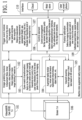
- FIG. 1 is a system block diagram for an augmented reality platform supporting a real-time or recorded video/image.
- the system can include one or a plurality (1:n) of input devices 101 including a video camera, a still camera, an IR camera, a 2D camera or a 3D camera.
- the input device 101 can be adapted to send information to one or more machine vision augmented reality modules 102, 103, 104, 105, 107, 108 and 109.
- the one or more machine vision augmented reality modules 102, 103, 104, 105, 107, 108 and 109 can be adapted to send information to one or a plurality (1:m) of screens 106.
- the one or more machine vision augmented reality modules 102, 103, 104, 105, 107, 108 and 109 can be adapted to send/receive information to/from an interface or user interface module 110.
- the interface 110 can be adapted to send/receive information to/from one or more of a cloud, a web/store or a user device, e.g., smart phone or tablet.
- the one or more machine vision augmented reality modules 102, 103, 104, 105, 107, 108 and 109 can include an image grabbing module 102, an eyes-match transformation module 103, an augmented reality module 104, a video/still recording module 105, a trigger event module 107, a control element module 108, and a factory calibration module 109.
- the image grabbing module 102 can include one or more of the following features: enhancement filters, format conversion, video frame separation, image cropping, image resizing, image stitching and the like.
- the image grabbing module 102 can be adapted to send information to the eyes-match transformation module 103.
- the image grabbing module 102 can be adapted to send/receive information to/from the trigger event module 107.
- the eyes-match transformation module 103 can be adapted to apply on the image the right mapping to match the camera point of view with theoretical mirror point of view (user eyes reflection) and fill the blind pixels if there are any after the mapping.
- the eyes-match transformation module 103 can be adapted to send information to the augmented reality module 104 and/or the video/still recording module 105.
- the eyes-match transformation module 103 can be adapted to send/receive information to/from the control element module 108.
- the eyes-match transformation module 103 can be adapted to send information to the one or plurality of screens 106.
- the control element module 108 can include one or more of the following features: control and management for setting the camera to optimize quality, for setting other hardware elements, an interface between algorithm modules and higher code/application/user interfaces, and push calibrated data from factory into the algorithm elements.
- the control element module can be adapted to send/receive information to/from the factory calibration module 109.
- the factory calibration module 109 can be adapted to define the mapping transformation between the camera and the user point of view in front of the screen. Also, factory calibration module 109 can be adapted to calibrate the image based on distance, a special location, user height or any combination thereof.
- Some applications do not require (but can nonetheless include) live augmented reality, like trying-on clothes when the user would like to see himself with the modification (one or more options).
- live augmented reality like trying-on clothes when the user would like to see himself with the modification (one or more options).
- the extracted object from the live scene is saved, it is easier to render multiple changes (color, texture, size, and the like).
- the second option is better to use. With the second option, the performance should be adapted to be as close as possible to the actual frame rate of the camera in order to avoid introduction of delay/lagging that can yield frame drops and poor performances.
- the rendering process be done in a DSP or GPU device in order to avoid introduction of delay into the video.
- the creation of the mask/model can be done for the first option (not real-time) in a CPU as well.
- the mask/model can be performed and calculated in the GPU/DSP as well.
- some of the trigger functionality can be completely automated, e.g., a process can be started if face detection or presence detection is made. Some of the triggers can be performed in a semi-automated fashion from the user interface module 110, which can include any way to control the computerized device. Some of the functionality of the trigger event is to calculate the image transformation based on geometric information, calibration, and/or real-time user tracking, e.g., location of the user, eyes, head, hands, position, movement and the like. The tracking can be done using one or more techniques such as background substation, pattern recognition, color segmentation, and the like. The transformation tracking calculation functionality can also be implemented in the other modules.
- the control element module 108 can be adapted to configure the system setup, camera device authentication and the like, can also provide information from the tracking transformation function into actual geometry transformation module or augmented reality module and the like.
- factory calibration module 109 some of the information needed to calculate the transformation to be applied on the image/video can be generated during factory calibration or can be calculated based on additional information on the actual orientation of the camera in the field, e.g., height above the floor or desk and the like, 3D point of view, lens field of view (FOV), and the like.
- the factory information plus the actual geometry of the implementation can be processed and delivered to the right element in the system that will use the information for better calibration and accuracy.
- the present invention can be used to send the video plus the means to transform it or the actual manipulated and transformed video to another address in the cloud or locally as a single or bidirectional video conference.
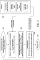
- FIG. 2 depicts an example of an augmented reality module, which can correspond with the augmented reality module 104 described above.
- the augmented reality module can have a function of allowing a user to virtually dress themselves.
- the system obtains input image or video from, for example, the EyesMatch computerized method 201 or from any other image/video source, e.g., user smartphone, security camera, Google glass, mobile camera or stationary camera. Additional embodiments can include additional geometric information that will help to calculate proportion like user height, gaze and the like. If the user video or image is coming from the EyesMatch module (calibrated image/video), a more comprehensive model can be created that allows for body measurements, object pose, size, highly accurate orientation detection and the like. The additional information that can be calculated from the calibrated object or video can allow for object fitting, object replacement and insertion of new objects into the frame/video.
- the election module 202 can obtain election information from interface 206 manually from the user (X,Y or name of object) or automatically from an electing method, e.g., a mechanism that can automatically detect predefined objects like pants, dress shirts and the like.
- the mask can be used for rendering as a simple black and white mask.
- additional information from the object's texture or appearance can be maintained.
- the mask can be applied on the original frame or video, and the RGB or gray scale texture shade or brightness scale on the object can be obtained. This information is much more accurate and convincing for color changes since it saves the original object's wrinkle texture, shading, light reflection, material signature and the like.
- the model mask can be constructed in layers for improved manipulation.
- Examples of a potential layer structure can be as follows:
- the rendering module 204 can be used to modify the specific layer/layers and regenerate the object out of the multiple layers resulting in a rendered video 205 that is extremely realistic. For example, if the user wore a red shirt, the red mask can be replaced with a blue mask to render the user wearing a blue shirt. Since all other masks remain the same, the blue shirt will be rendered with all of the shading, brightness, reflection, texture, etc., of the red shirt, thus rendering a very realistic blue shirt having the same folds and following the same body contours as the red shier.
- the effect of some layers can be introduced by multiplication or by adding the modified layer to the frame. Subtraction and division can also define relationships between layers. Additional techniques that allow for more complex item manipulation include a registration technique, which can based on a few points stretch/transform an object or material to fit within the boundaries of the manipulated object.
- the rendering module can render the object with an enhanced rendering technique of interpolating the object and the frame into higher resolution, can combine the object at high resolution, can smooth the edges, and can decimate the object back to the required resolution with better quality of integration into the frame. Additional techniques include working directly on the edge of the object by averaging with some weighting factor the value of the pixel in order to better blend the object with the background color.
- the obtained black and white mask is applied on the original color image and the 3D model for color and texture changes is obtained.
- the model can be 2D alpha channel of gray scale or 3D in the color space.
- Module 410 can obtain a 2D or 3D model of the object. In case of video from a single camera, it is possible to obtain a 3D model even if the user is moving in front of the camera, e.g., turning around in front of the camera. In this case, it is also possible to obtain object measurement in multiple cuts to estimate the user's 3D body curves.
- Measurements in pixels can be translated into centimeters (cm) according to the predicted curve, e.g., the neck can be modeled as a cylinder so the measured width of the neck in pixels can represent the 2 x radials in pixels, then the radials in pixels can be converted into cm per the calibration.
- the bust for a man has a more elliptical model, so the translation will be a bit different. If additional side measurements are available, such measurements can be added to provide more accurate information to the model.
- the combination of EyesMatch with face recognition can allow the operator to install a camera above a user's height, for example, above a door facing down about 30-45 degrees; such installation allows the user to move freely below the camera.
- the detectable face recognition range is about 1-5 meters in front of the camera. This is an advantage since known face recognition systems are not very accurate if the user's head is scanned at an angle of +/- 15 degrees.
- the video, stills or the analyzed data can be recorded with a video/still recording module 605 directly from the camera, from the EyesMatch transformation module 604, from the processed image or from data out of the sensors.
- the device can have multiple image computing capability, EyesMatch geometric capability, e.g., in the EyesMatch transformation module 703, body measurement and user authentication, e.g., in the security scanning module 704, and augmented reality capabilities, e.g., in the augmented reality module 706, where the image can be manipulated on the main stream or in parallel to the main stream, e.g., manipulations can include a change of a user's body type, color, items held by the user, hair style, complete user disappearance and the like.
- manipulations can include a change of a user's body type, color, items held by the user, hair style, complete user disappearance and the like.
- the video stream can feed another device like a robot, a head mounted display, a user application and the like.
- the capability for example, can be done in real-time or offline.
- the activation of the device can be done, for example, periodically, in response to a trigger event or manually, as needed or desired.
- Video can be shared real-time with additional stations. There are multiple ways to share the video. Some exemplary scenarios are discussed in detail below.
- both stations are EyesMatched/calibrated to the same geometries and dimensions; every one of the stations creates a full body mirror and sends it to the remote location/locations.
- the full-body and EyesMatch experience will occur on the video conference as well, and the user will get the feeling they are looking into each other's eyes.
- the screen can be divided to allow multiple users from multiple locations to be displayed at the same time, or multiple screens can be placed one next to the other as depicted, for example, in FIG. 8c .
- FIG. 8c depicts multiple mirrors/full body stations with split screen or multiple screens. As shown in FIG. 8c , the order the users are depicted in the mirror allows for correct gaze communication. When the user is looking to the right, for example, on the remote screen, after the flip, he will be seeing the user looking left toward the remote user.
- the remote location in addition to the EyesMatch or any computerized image processing at one side, can have additional computerized capability to manipulate on the far end video based on the local user tracking, e.g., if the user gets closer to the screen, the far end video or image will be processed to look a bit bigger and projected to provide a better feeling of a live session. Another example is when a user gets closer on one end, he will see a wider FOV of the far end.
- the virtual mirror control and virtual system can include one or more interfaces to control the mirror, e.g., automatic gesture, voice, eye pointing, mobile application, remote expert, local assistance and the like.
- the virtual mirror control and virtual system can include a comprehensive combination of interfaces, including the following: playing a recorded video (automatic/manual); advance effects (item color manipulation, augmented reality features, gaming features, background change, 3D effect, lighting effect and the like); screen mode (orientation/full size or split screen); sharing techniques and methods to share the experience with friends/experts in real-time and on the go; mobile user application for controlling display and sharing, for example, sharing of personal videos and images taken from the virtual mirror or the user mobile device; retail or enterprise remote for general management (provide retailer information about the user in real-time with advanced control and analytics capability); and a module to teach the user how to operate the mirror (animation, video, voice, visual hints and the like).
- FIGS. 14 , 15 and 16 depict examples of a virtual mirror user interface (UI) flow that can be sequenced together to simulate a mirror experience.
- UI virtual mirror user interface
- the mirror is capable of tracking the user once the user enters a specified zone in front of the mirror. Based on the tracking, the video engine can calculate a transformation of the image to mimic mirror behavior.
- the engine can take a default setting (e.g., 2m) and apply the 2m transformation on the camera stream to create a mirror effect on the environment as depicted, for example, in FIG. 14 .
- a default setting e.g. 2m
- the mirror can present other videos of models, commercials and the like.
- the trigger zone can be designated with a carpet.
- the carpet can be designed with a specific pattern and color that improves the tracking and detection of the user.
- the colors of the carpet can improve the quality of the video. For example, lighter colors can be used to improve lighting conditions and improve the quality of the resulting video.
- the pattern on the color can be changed of around 5-10 cm with lighter and darker colors so that when a user stands with dark or light color shoes, the user shoes will be easily detected and tracked, and the maximum distance error will not be higher than 5-10/2.
- the carpet can include instructions to the users informing the user how to operate the mirror.
- an operation device can be provided where a user can touch their foot on a receptive pad to operate the mirror with their legs and feet rather than their hands or voices.
- the mirror can be configured so that, when the user steps into the tracking/registration zone in front of the station, the video engine reacts and starts tracking the object. Based on the object location, the video engine can adjust the video transformation to mimic mirror behavior. Additional input to the tracking can include the user's height, spatial location, pose and the like, as described in the EyesMatch process. At this point, the user is still not registered to the system, so an additional process of user identification can be performed.
- the authentication can include face recognition, a special card that a user can present to the system for scanning, a user mobile device (audio, wireless, QR code), or other biometric registration feature.
- the mirror can record for N seconds, e.g., 10-13 seconds is enough time to allow the user to get a good impression on the way a particular item looks and can include, e.g., the user turning around and the like.
- the mirror can be configured to start recording automatically when it recognizes the user, if the user does not want such auto-recognition, the mirror can be configured to save the video, the user can trigger one of the previous thumbnails, the mirror can be configured to switch to a display mode and the mirror can be configured to play the video. That is, the user can be prompted to execute a process by which a particular scene is cut by the user and not saved in the system.
- a thumbnail can be added on the mirror, which can be useful when the screen is in a narrow configuration, e.g., 21:9, or any other wide screen configuration.
- the thumbnail can be displayed so as to pop up in a separate bar next to the mirror stream or under the mimicked video stream. This feature can be useful when the screen is wider than required or proportioned for the mimicked mirror stream.
- a recording indicator can be displayed as well.
- the recording indicator can include display of a phrase like "REC", a red colored circle and the like.
- facial recognition is not entirely reliable 100% of the time
- additional recognition features can be displayed so as to pop up on the screen for an appropriate amount of time, such as a few seconds.
- a QR bracket GUI is opened and the user can show the mirror a QR badge or QR that was sent to his unique application, e.g., on a smartphone, and effectively communicate to the system that the present facial image is associated with the authenticated user.
- This technique can be used to allow semi-automatic user merging in the event a particular user has more than one facial account.
- additional facial measurements/improvements can be performed to improve the recognition of the user over time.
- additional control capability can be added as well, e.g., start recording, erase video, add video effects like lightening, color changes, background selection and the like.
- all the videos can be uploaded to the cloud and can be erased in the local station after some period of time.
- the videos can be processed after recording with additional effects that improve the video or change the video to reflect augmented reality effects or for BMI/tailor/body line measurements analysis.
- the video recording can include the audio recording of the environment for further analysis.
- the video recording can include WLAN recording of the environment to record the MAC of the users and later on with further correlation, can be adapted to associate the MAC of the mobile device to the user.
- a system for facilitating a user's control of the mirror may be provided.
- the user if the user is still in the predefined zone and was recognized by the mirror once, as long as he is still standing there and no one else is being recognized, the user will be able to control the mirror, e.g., play, start and stop images/videos, delete images/videos, add augmented reality features and the like.
- the user can also control the mirror through gesture control or from his device, e.g., smartphone, through a dedicated application or additional control features as part of the retail application.
- the gesture control can enable some basic functionality and the user application can be allowed to enable much more functionality relative to the gesture control.
- the assistant in the store or an assistant available virtually/remotely in the cloud can assist the user in operating the mirror.
- the user can set his own preferences for the UI from his application or from the web. All user dedicated settings can be added to the user's account, e.g., the user can change the time of a recording, the number of thumbnails and the like.
- the user can see his last n videos.
- the videos may or may not have been taken in the specific mirror location, but may be accessed at a central storage location, e.g., from the cloud.
- the user can set the appearance of the thumbnails of the local try-on videos. From his application, the user can see all the thumbnails and be able to touch them or any other election method to activate play of the video associated with the specific thumbnail.
- the thumbnails are configured so as to pop up on top of the mimicked mirror stream as can be seen, for example, in FIG. 15 .
- the thumbnails can be sent to the background when the video is playing or in split mode when there is no gesture control identification as shown, for example, in FIG. 16 .
- the user can also set the screen to a split mode as shown, for example, in FIG. 16 .
- FIG. 16 depicts a side-by-side setting where the user can still see himself in real-time on one side of the screen and can play previously recorded videos on the other half.
- the remote control of the user can obtain the identified user information automatically so the store assistant can send the user link to his account for registration or to help the user with additional capability like changing clothes colors or changing clothes in general.
- the user can use his mobile device to initiate a video call in the mirror with a remote expert or a friend that can advise him in real time.
- the call can be from a dedicated application or any other third-party application like Skype.
- the mirror video stream can be fed to the local Skype and the remote user can get the mirror stream in real time.
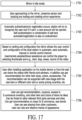
- FIG. 17 depicts one embodiment of a suggested flow of usage. Specifically, FIG. 17 depicts an embodiment of user flow of usage of the additional embodiments depicted in FIGS. 14 , 15 and 16 and their associated descriptions.
- the mirror is in idle position, and in step 1702, as a user approaches the mirror, the user's presence is sensed, e.g., by change in the image seen by the camera, and the system initiates operation in mirror mode.
- the system initiates authentication procedure to identify and authenticate the user. For example, in one embodiment the system uses face recognition to identify and authenticate the user, while in another embodiment the user may be authenticated using a device such as a smartphone with capabilities such as, WiFi, Bluetooth, NFC, etc. If the user has not been identified, e.g., it's a new user, the user may be prompted to open an account. Otherwise, the user may proceed as a guest, albeit some features, such as remote access to stored images, may not be available.
- step 1704 the user is given user control over the display.
- the specific control preferences are saved for each particular user and are activated once the user has been recognized.
- general user interface is enabled, e.g., a hand gesture activated interface.
- prior trials are presented as thumbnails on the side of the main display.
- thumbnails When the user raises the hand corresponding to the side of the thumbnails, depending on the height of the hand, a corresponding thumbnail is highlighted for selection. As the user raises or lowers the hand, another thumbnail corresponding to the height of the hand is highlighted for selection. Then, when the user closes his fist, the highlighted thumbnail is selected and the corresponding image or video is displayed on the main screen.
- the images and video of each session may be stored on the cloud, and may be accessible remotely using, e.g., smartphones, tablets, etc.
- a user may converse with friends remotely and get their opinion on the outfit the user is trying.
- the user may send the friend a link to the recorded trial or to a live streaming video from the system.
- the user may share the shopping experience with people located remotely.
- the system since the system is able to identify the user and also calculate parameters of the user, e.g., weight, height, etc., the system may be able to access a database of available items that would be recommended to the user based on these parameters. More specifically, if the user has recorded two trials of two different shirt within the same session, the system can decipher that the user is interested in purchasing a shirt and make either alternative recommendations, i.e., different shirts, or complimentary recommendations, e.g., specific pants that go well with the tried on shirts. Also, since the system can identify the shirt and the brand of the shirt, it may be able to offer specific incentive from that manufacturer, as exemplified in 1706.
- a complimentary application can enable additional features and settings, e.g., an advanced user that is comfortable with gesture control can enable more gestures that will help to operate advanced features without use of a tactile interface application.
- an advanced user that is comfortable with gesture control can enable more gestures that will help to operate advanced features without use of a tactile interface application.
- users that are not comfortable with hand gestures such users can be provided with basic automated features and the mobile application can be used to operate the other advanced functionality.
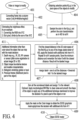
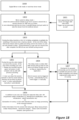
- Figure 18 is a block diagram for explaining a delay mode operation of the mirror.
- the delay mode can be implemented in any of the embodiments described herein.
- the delay mode may be implemented in software, hardware or combination of software and hardware.
- the delay mode may be implemented in a computer readable media storing a program that, when executed by a processor, causes the mirror to implement the delay mode of operation.
- the delay mode can be best understood by reference to it solution to one well-known deficiency of traditional mirror. Namely, when a person tries an outfit in front of a traditional mirror, that person has difficulties seeing how the outfit looks in different angles, and especially from the back. This problem is solved by the various implementations of the delay mode, as exemplified below.
- the delay mode may be implemented many ways.
- the system may be set with two parameters: delay time and recording period.
- Delay time indicates how long the delay of the replay is
- the recording period indicates how long the recording session is.
- the recoding period may be set to 20 seconds.
- the delay may be set, e.g., zero to five seconds.
- the system records a session of length 20 seconds. If the delay is set to zero, the system will start replaying the session immediately after it completed recording the 20 seconds session. Conversely, if the delay time is set to five seconds, the session will be played five seconds after completing the 20 seconds session recording.
- Various embodiments handle the projection on the screen during recording differently.
- the system before and/or during the recording session the system projects on the screen instructions for the user, e.g., cuing the start of the session or instructing the user to spin.
- the cuing can start after the user activating the delay mode session, e.g., by selecting a start button, or automatically when the mirror system recognizes the presence of a user in front of the mirror and exits idle mode.
- the mirror system projects a live mirrorized video of the session, but also records and replays the session according the parameter setting of the delay mode.
- One advantage of projecting a live mirrorized video of the session is that it maintains the appearance of standard mirror, making it easier for a user to interact with the mirror system.
- the processor applies the various transformations as detailed in the above embodiments so as to generate mirrorized video stream, which is displayed on the screen, but also stored in memory.
- the mirrorized video is fetched from memory and is replayed on the screen.
- Block 1800 indicates that the mirror is in idle mode or in real-time mirror mode, as explained in various embodiments herein.
- real-time mirror mode the user can see himself/herself live in the digital mirror.
- the camera sends a video stream to the processor, which processes the stream to be projected as digital mirror stream (mirrorized video).
- the mirror may be in some idle mode, showing commercials, demo mode, explanation how to operate the mirror, etc.
- Block 1801 indicates that a user has approached the mirror. This event may be detected by the mirror system automatically by, e.g., analysis of the video stream from the camera, using motion sensor, etc. The appearance of the user in front of the screen may be used to automatically enter the delay mode. Alternatively, switching into delay mode can be done manually by user using, e.g., remote control, voice, gesture, etc.
- the delay mode can be configurable i.e., the length of the delay and the length of the recording session.
- the delay mode should be configured to provide enough time so user can see himself/herself in semi real-time and preview the movement while still have the feeling of seeing himself/herself in a mirror.
- the image is frozen on the screen, or some graphics are displayed on the screen.
- a GUI is hiding the frozen image, so users can't see what is happening to the mirror/camera stream.
- Block 1804 represents the delay session.
- the delay mode is implemented by simply sending the video stream to a FIFO buffer, wherein each frame is fetched after a set time delay.
- the length of the delay can be set beforehand. Consequently, once the mirror system enters the delay mode in the embodiment, the user continuously sees on the screen a semi-real time, i.e., a delayed mirrorized video stream.
- the duration of the delay mode can also be configured e.g. 8-30sec, after which the mirror system returns to real-time mirror mode. During the period of time of the delay mode the user will see the mirror stream in delay, i.e., semi-real time.
- the recording is starting at the end of the switching period, in one embodiment the recording starts after few second into the delay mode, while in one embodiment the recording starts and stops by automated event detection, like orientation of user face, user starting to turn around, etc., as will be further explained with reference to Figure 20 .
- a GUI or UI is being rendered on the screen, and may hide completely or semi transparently the freezing of the real-time stream. In that way the transitions between real-time and delay mode are smoother.
- the Ul basically hides the period of accumulating the buffer.
- mirror or remote kiosk will transmit a beacon and the user's mobile device or smart watch can pick it and use the information to get access and control on the mirror.
- the user's mobile device or smart watch can pick it and use the information to get access and control on the mirror.
- identified user that get access will automatically get the recoded session into his device or cloud account.
- the mirror station can support instruction to the user, so that when the system identifies a user that is not controlling the mirror in the correct manner, a short explanation can pop up and guide the user through the process.
- the mirror can insert commercials, coupons and logos into the mirror in idle mode, within a specified portion of the mirror or via split screen mode.
- the mirror can also introduce commercials, coupons and logos into recorded videos so a user can view the video with the commercial/coupon/logo. These displays can be sold as advertising.
- the user can share the commercial/coupon/logo.
- the user can be offered an incentive in exchange for sharing the commercial/coupon/logo.
- the user's try on of clothing can be analyzed for measurements/characteristics such as BMI, sex, origin, age, body measurements, facial expression, voice expression, recommended sizes and the like.
- This data can be incorporated into ecommerce applications. This data is of high value and can be shared with brands, the user, a third party based on an agreement with the user and the brands, etc.
- a revenue stream can be generated from the analyzed data regarding the user, for example, by presenting the user with focused and accurate advertising.
- the user can be presented with a display including a suggestion and/or incentive for a particular item tried on by the user, for example, with different colors.
- This method presents a further opportunity to promote up-selling.
- Augmented reality can be used to promote up-sales. Specifically, based on information obtained by the mirror and other user tries, a more compelling augmented reality display can be generated based on a combination of information about the user and similar users that have a similar body type.
- the social network of the user can be integrated in a manner to help the user and/or comment on the user's contemplation of the item.
- the system can be configured to share the user's videos.
- the social networking features can be used to enlarge the database of addressable customers.
- the user can upload their own photos
- the video engines can be configured to process the images and provide similar analysis of BMI, face origin and the like.
- the system can provide recommended sizes for ecommerce applications.
- the system can show the item that was bought in different colors. In this manner, the mirror can be used to obtain marketing information for an appropriate database even when the user isn't physically standing in front of the mirror itself.
- the user can see his predicted size in the application and update the measurements, which can be used to improve the size prediction model and include adjustments for particular brands.
- the screen can be mounted so as to stand on the wall either vertically or horizontally or can be switchable between vertical and horizontal (by a larger or similar mechanical solution, the screen can be tilted, rotated and the like).
- the screen can be mounted on a dedicated stand, mounted on a wall or mounted behind the wall. When the screen is inside the wall, thermal ventilation duct should be provided to support the screen and the computing device.
- the digital mirror system 2110 comprises of an enclosure 2112, which houses a processor.
- the processor is a mini-PC, such as the Brix series, available from Gigabyte Technology TM of Taiwan, and which is available for consumer purchase in electronics stores, such as Fry's Electronics and MicroCenter.
- the advantage of using a mini PC is that it's an ultra compact PC design, measuring a mere 62 x 111.4 x 114.4 mm. This makes the entire system extremely compact and easily attachable to the back of any TV using an attachment mechanism 2115.
- the attachment mechanism 2115 can be a VESA bracket in case the TV is mounted to the wall, or other attachment mechanism, such as a specially designed mechanical clamp, a double-sided adhesive, Velcro ® , etc.
- a two part attachment mechanism may be used, indicated as 2115 part attached to the enclosure 2112, and part 2115' attached to the back of the TV 2005, wherein the two parts 2115 and 2115' attach to each other, either mechanically, using adhesive, Velcro ® , etc.
- the processor inside the enclosure includes a microprocessor, such as Intel Core, memory, a DSP to process the video, wireless transmitters, such as WiFi, Bluetooth, etc.
- the Brix includes an Intel Core processor, Solid State or hard drive memory, wireless transmitters, and LAN connection.
- the Brix includes a 4K resolution HDMI output 2117, which is connected to the HDMI input of the TV 2005.
- the power input to the processor which is connected to a standard 110V or 240V outlet, depending on the country.
- a high quality digital signal processor may be used to obtain the best results for processing the video signals.
- the Intel ® Iris ® Pro graphics card may be used for the video processing.
- the enclosure 2112 includes an extension 2113 upon which a photosensor housing 2114 is mounted.
- the photosensor housing is mounted to the extension 2113 via an adjustable coupler 2116, so that the elevation of the field of view of the photosensor can be adjusted by, e.g., rotating the housing 2114 about coupler 2116, as shown by the curved arrow.
- the photosensor (not shown) is housed inside the housing 2114 and sends its signal to the processor for processing over cable 2118, shown in Figure 21 for illustration purposes, but should be hidden from view. Cable 2118 may be electrical cable or fiber optics.
- system for enabling real-time and delayed video play may be used to mimic a mirror to thereby enable a user to try a clothing item.
- the system may also be used for various training purposes, wherein the mirror mimicking function may be omitted.
- the system comprises: an enclosure configured to house therein a processor, the enclosure having an extension; an optical sensor housing coupled to the extension; a processor housed within the enclosure, the processor comprising a memory and a video engine and having an output configured to sending digital images to a digital screen; an optical sensor housed within the optical sensor housing and having means to send images to the processor; and an attachment mechanism configured to attach the enclosure to a back of a digital screen.
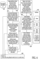
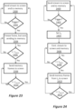
- FIG. 23 illustrates a flow chart for a process that can be executed by any of the embodiments disclosed herein.
- Step 2300 illustrate a normal operating condition, wherein the live video stream from the photosensor is presented on the screen and also saved in memory.
- the live video stream can be processed before presenting it on the screen and/or storing it in memory, by applying the flipping and transformation so that it mimics a mirror. Otherwise no flipping or transformation is needed.
- step 2302 when a trigger is issued, e.g., by a user clicking an icon, by analysis of motion in the live video stream, etc., the system enters the delay mode.
- the system enters delay mode in step 2304 the frame presented on the screen at that instance is frozen or paused.
- the live video stream from the photosensor is continued to be stored in the memory.
- a delay time is being monitored and when time reaches the present delay time at 2306, the frames from the memory are sent to the screen at 2308, starting from the frame immediately following the frozen frame.
- a delay period is monitored and, when at 2310 the delay period is reached, the system reverts to normal operation 2300.
- the delay time needs to be shorter than the delay period. Also, from experience it has been shown that the delay time is best set from one to five seconds, while the delay period from five to thirty seconds.
- the screen can have a regular proportion, i.e., 16:9, and the setting of the display can be split screen or dark bars on the sides to yield the mirror proportion, i.e., 21:9.
- the screen can come in a matte finish to eliminate reflections that can be seen on dark colors.
- the screen when the user wears black, and the screen is not matte-finished, the user can see his own true mirror reflection; this effect is not wanted and can diminish, distort or completely ruin the virtual mirror effect.
- the cameras or the controlled cameras can be located in the frame.
- the camera can be mounted above the screen frame, can be hidden and can be mounted on the wall.
- the camera can be provided with a shade that can be filtered out from the image. Since the camera is facing down, a cover that will hide most of the camera body can block the view from a distance.
- a background can be used that enables better white balancing that results in higher quality videos.
- Lighting can include a combination of white, yellow or any combination in a spot or a projector combination and can be configured to improve the video quality and the colors.
- a dedicated carpet can be used to allow background changes, to define a user zone, to improve user detection and tracking in front of the mirror, to instruct the user where to stand and to instruct the user on how to operate the mirror.
- modules or programs corresponds to a set of instructions for performing a function described above.
- modules and programs i.e., sets of instructions
- memory may store a subset of the modules and data structures identified above.
- memory may store additional modules and data structures not described above.
- the illustrated aspects of the disclosure may also be practiced in distributed computing environments where certain tasks are performed by remote processing devices that are linked through a communications network.
- program modules can be located in both local and remote memory storage devices.
- various components described herein can include electrical circuit(s) that can include components and circuitry elements of suitable value in order to implement the embodiments of the subject innovation(s).
- many of the various components can be implemented on one or more integrated circuit (IC) chips.
- IC integrated circuit
- a set of components can be implemented in a single IC chip.
- one or more of respective components are fabricated or implemented on separate IC chips.
- a component As used in this application, the terms “component,” “module,” “system,” or the like are generally intended to refer to a computer-related entity, either hardware (e.g., a circuit), a combination of hardware and software, software, or an entity related to an operational machine with one or more specific functionalities.
- a component may be, but is not limited to being, a process running on a processor (e.g., digital signal processor), a processor, an object, an executable, a thread of execution, a program, and/or a computer.
- a processor e.g., digital signal processor
- an application running on a controller and the controller can be a component.
- One or more components may reside within a process and/or thread of execution and a component may be localized on one computer and/or distributed between two or more computers.
- a “device” can come in the form of specially designed hardware; generalized hardware made specialized by the execution of software thereon that enables the hardware to perform specific function; software stored on a computer-readable medium; or a combination thereof.
- Computer-readable storage media generally can be any available storage media that can be accessed by the computer, is typically of a non-transitory nature, and can include both volatile and nonvolatile media, removable and non-removable media.
- Computer-readable storage media can be implemented in connection with any method or technology for storage of information such as computer-readable instructions, program modules, structured data, or unstructured data.
- Computer-readable storage media can include, but are not limited to, RAM, ROM, EEPROM, flash memory or other memory technology, CD-ROM, digital versatile disk (DVD) or other optical disk storage, magnetic cassettes, magnetic tape, magnetic disk storage or other magnetic storage devices, or other tangible and/or non-transitory media which can be used to store desired information.
- Computer-readable storage media can be accessed by one or more local or remote computing devices, e.g., via access requests, queries or other data retrieval protocols, for a variety of operations with respect to the information stored by the medium.
- Communications media typically embody computer-readable instructions, data structures, program modules or other structured or unstructured data in a data signal that can be transitory such as a modulated data signal, e.g., a carrier wave or other transport mechanism, and includes any information delivery or transport media.
- modulated data signal or signals refers to a signal that has one or more of its characteristics set or changed in such a manner as to encode information in one or more signals.
- communication media include wired media, such as a wired network or direct-wired connection, and wireless media such as acoustic, RF, infrared and other wireless media.
Landscapes
- Engineering & Computer Science (AREA)
- Multimedia (AREA)
- Signal Processing (AREA)
- Business, Economics & Management (AREA)
- General Business, Economics & Management (AREA)
- Computer Networks & Wireless Communication (AREA)
- Databases & Information Systems (AREA)
- General Physics & Mathematics (AREA)
- Computer Hardware Design (AREA)
- Theoretical Computer Science (AREA)
- Physics & Mathematics (AREA)
- Human Computer Interaction (AREA)
- Processing Or Creating Images (AREA)
- Controls And Circuits For Display Device (AREA)
- User Interface Of Digital Computer (AREA)
- Image Analysis (AREA)
Claims (7)
- Procédé mis en oeuvre par ordinateur pour faire fonctionner un système présentant un moniteur, une caméra et un processeur, de manière à afficher séquentiellement un flux vidéo en temps réel et un flux vidéo retardé sur le monitor pour permettre à un utilisateur une expérience améliorée d'une session de visionnage, caractérisé en ce que le procédé comprend les étapes consistant à :définir un temps de retard de N secondes ;définir une période de retard de M secondes ;obtenir une alimentation vidéo en direct à partir de la caméraenvoyer simultanément l'alimentation vidéo au monitor pour qu'elle soit affichée en tant que flux vidéo en temps réel et sauvegarder l'alimentation vidéo en tant que trames dans la mémoire ;à réception d'un déclencheur, mettre en oeuvre :l'indication d'un temps de déclenchement au moment de la réception du déclencheur et le stockage du temps de déclenchement dans la mémoire ;le comptage de N secondes à partir du temps de déclenchement puis l'extraction des trames de la mémoire et l'envoi au monitor pour affichage en tant que flux vidéo retardé, en commençant de la trame qui a été stockée au temps de déclenchement et la poursuite simultanée du stockage du flux vidéo dans la mémoire ;après l'extraction d'une série de trames pendant M secondes, l'arrêt de l'extraction et l'inversion de l'envoi de l'alimentation vidéo au monitor pour affichage en tant que flux vidéo en temps réel, dans lequel N est plus court que M.
- Procédé mis en oeuvre par ordinateur pour faire fonctionner un système présentant un moniteur, une caméra et un processeur, de manière à afficher séquentiellement un flux vidéo en temps réel et un flux vidéo retardé sur le monitor pour permettre à un utilisateur une expérience améliorée d'une session de visionnage, caractérisé en ce que le procédé comprend les étapes consistant à :définir un temps de retard de N secondes ;définir une période de retard de M secondes ;obtenir une alimentation vidéo en direct à partir de la caméraenvoyer simultanément l'alimentation vidéo au monitor pour qu'elle soit affichée en tant que flux vidéo en temps réel et sauvegarder l'alimentation vidéo en tant que trames dans la mémoire ;à réception d'un déclencheur, mettre en oeuvre :le gel d'une trame présentée dans un cas où le déclencheur a été délivré, mais la poursuite de l'envoi de vidéo en temps réel à la mémoire pour stockage ;le comptage de N secondes à partir du temps de déclenchement puis l'extraction des trames de la mémoire et l'envoi au monitor pour affichage en tant que flux vidéo retardé, en commençant de la trame qui suit immédiatement la trame gelée et la poursuite simultanée du stockage du flux vidéo dans la mémoire ;après l'extraction d'une série de trames pendant M secondes, l'arrêt de l'extraction et l'inversion de l'envoi de l'alimentation vidéo au monitor pour affichage en tant que flux vidéo en temps réel, dans lequel N est plus court que M.
- Procédé selon la revendication 1 ou la revendication 2, caractérisé en ce que N est défini de une à cinq secondes et M est définie de cinq à trente secondes.
- Procédé selon la revendication 1 et la revendication 2, caractérisé en ce que le déclencheur est généré en analysant en continu l'alimentation vidéo et en délivrant le déclencheur quand il est déterminé que l'utilisateur met en oeuvre un mouvement de déclencheur.
- Procédé selon la revendication 1 et la revendication 2, caractérisé en ce que le déclencheur est généré en analysant en continu l'alimentation vidéo et en délivrant l'indication quand il est déterminé qu'un utilisateur est entré dans le champ de vision de la caméra.
- Procédé selon la revendication 1 et la revendication 2, caractérisé en ce qu'il comprend en outre :le basculement de chaque trame de l'alimentation vidéo autour d'un axe vertical de manière à inverser les côtés droit et gauche de la trame ;l'application d'un mappage de transformation à chaque trame de l'alimentation vidéo afin de modifier les trames de telle sorte qu'elles apparaissent pour imiter un reflet d'un miroir, pour ainsi obtenir des trames transformées.
- Procédé selon la revendication 6, caractérisé en ce que le basculement et l'application d'un mappage de transformation à chaque trame sont effectués avant l'envoi de l'alimentation vidéo au monitor pour qu'elle soit affichée en tant que flux vidéo en temps réel et avant la sauvegarde de l'alimentation vidéo en tant que trames dans la mémoire.
Priority Applications (1)
| Application Number | Priority Date | Filing Date | Title |
|---|---|---|---|
| EP24185308.4A EP4465227A3 (fr) | 2015-01-09 | 2016-01-08 | Dispositifs, systèmes et procédés de présentation vidéo à retard automatique |
Applications Claiming Priority (2)
| Application Number | Priority Date | Filing Date | Title |
|---|---|---|---|
| US201562101397P | 2015-01-09 | 2015-01-09 | |
| PCT/US2016/012738 WO2016112346A1 (fr) | 2015-01-09 | 2016-01-08 | Dispositifs, systèmes et procédés de présentation de vidéo à retard automatique |
Related Child Applications (1)
| Application Number | Title | Priority Date | Filing Date |
|---|---|---|---|
| EP24185308.4A Division EP4465227A3 (fr) | 2015-01-09 | 2016-01-08 | Dispositifs, systèmes et procédés de présentation vidéo à retard automatique |
Publications (3)
| Publication Number | Publication Date |
|---|---|
| EP3243331A1 EP3243331A1 (fr) | 2017-11-15 |
| EP3243331A4 EP3243331A4 (fr) | 2018-08-08 |
| EP3243331B1 true EP3243331B1 (fr) | 2024-07-03 |
Family
ID=56356509
Family Applications (2)
| Application Number | Title | Priority Date | Filing Date |
|---|---|---|---|
| EP16735516.3A Active EP3243331B1 (fr) | 2015-01-09 | 2016-01-08 | Dispositifs, systèmes et procédés de présentation de vidéo à retard automatique |
| EP24185308.4A Pending EP4465227A3 (fr) | 2015-01-09 | 2016-01-08 | Dispositifs, systèmes et procédés de présentation vidéo à retard automatique |
Family Applications After (1)
| Application Number | Title | Priority Date | Filing Date |
|---|---|---|---|
| EP24185308.4A Pending EP4465227A3 (fr) | 2015-01-09 | 2016-01-08 | Dispositifs, systèmes et procédés de présentation vidéo à retard automatique |
Country Status (4)
| Country | Link |
|---|---|
| EP (2) | EP3243331B1 (fr) |
| CN (2) | CN107211165A (fr) |
| ES (1) | ES2984065T3 (fr) |
| WO (1) | WO2016112346A1 (fr) |
Families Citing this family (20)
| Publication number | Priority date | Publication date | Assignee | Title |
|---|---|---|---|---|
| CN107105311B (zh) * | 2017-05-25 | 2020-06-19 | 北京小米移动软件有限公司 | 直播方法及装置 |
| CN107590481A (zh) * | 2017-09-28 | 2018-01-16 | 北京小米移动软件有限公司 | 穿衣镜、数据处理方法及装置 |
| US11212431B2 (en) * | 2018-04-06 | 2021-12-28 | Tvu Networks Corporation | Methods and apparatus for remotely controlling a camera in an environment with communication latency |
| CN109151368B (zh) * | 2018-09-13 | 2021-11-23 | 广州市保伦电子有限公司 | 一种小型空间会议中控系统 |
| US11641439B2 (en) | 2018-10-29 | 2023-05-02 | Henry M. Pena | Real time video special effects system and method |
| US10388322B1 (en) | 2018-10-29 | 2019-08-20 | Henry M. Pena | Real time video special effects system and method |
| US11044420B2 (en) | 2018-10-29 | 2021-06-22 | Henry M. Pena | Real time video special effects system and method |
| US12452383B2 (en) | 2018-10-29 | 2025-10-21 | Henry M. Pena | Fast and/or slow motion compensating timer display |
| US11689686B2 (en) | 2018-10-29 | 2023-06-27 | Henry M. Pena | Fast and/or slowmotion compensating timer display |
| US11218646B2 (en) | 2018-10-29 | 2022-01-04 | Henry M. Pena | Real time video special effects system and method |
| US10404923B1 (en) | 2018-10-29 | 2019-09-03 | Henry M. Pena | Real time video special effects system and method |
| CN109770885A (zh) * | 2019-03-25 | 2019-05-21 | 合肥工业大学 | 一种基于预览帧的快速心率检测方法 |
| CN111954052B (zh) * | 2019-05-17 | 2022-04-05 | 上海哔哩哔哩科技有限公司 | 显示弹幕信息的方法、计算机设备及可读存储介质 |
| CN111309212A (zh) * | 2020-02-28 | 2020-06-19 | 厦门理工学院 | 一种分屏对比的试衣方法、装置、设备及存储介质 |
| US11690435B2 (en) | 2020-07-07 | 2023-07-04 | Perfect Mobile Corp. | System and method for navigating user interfaces using a hybrid touchless control mechanism |
| US11647158B2 (en) | 2020-10-30 | 2023-05-09 | Microsoft Technology Licensing, Llc | Eye gaze adjustment |
| US11871147B2 (en) | 2021-06-09 | 2024-01-09 | Microsoft Technology Licensing, Llc | Adjusting participant gaze in video conferences |
| WO2023275661A1 (fr) | 2021-06-30 | 2023-01-05 | 株式会社半導体エネルギー研究所 | Dispositif électronique |
| CN113709514B (zh) * | 2021-09-02 | 2023-06-23 | 北京一起教育科技有限责任公司 | 一种数据处理方法、装置和电子设备 |
| CN115134658B (zh) * | 2022-05-27 | 2024-05-14 | 阿里巴巴云计算(北京)有限公司 | 视频处理方法、装置、设备及存储介质 |
Citations (1)
| Publication number | Priority date | Publication date | Assignee | Title |
|---|---|---|---|---|
| US20050013467A1 (en) * | 2003-07-16 | 2005-01-20 | Mcnitt Michael J. | Method and system for physical motion analysis and training of a golf club swing motion using image analysis techniques |
Family Cites Families (13)
| Publication number | Priority date | Publication date | Assignee | Title |
|---|---|---|---|---|
| US20080079820A1 (en) * | 2004-12-17 | 2008-04-03 | Mcspadden Leslie J | Image Capture and Display Arrangement |
| US8976160B2 (en) * | 2005-03-01 | 2015-03-10 | Eyesmatch Ltd | User interface and authentication for a virtual mirror |
| US8970569B2 (en) * | 2005-03-01 | 2015-03-03 | Eyesmatch Ltd | Devices, systems and methods of virtualizing a mirror |
| US8982109B2 (en) * | 2005-03-01 | 2015-03-17 | Eyesmatch Ltd | Devices, systems and methods of capturing and displaying appearances |
| US20070040033A1 (en) * | 2005-11-18 | 2007-02-22 | Outland Research | Digital mirror system with advanced imaging features and hands-free control |
| GB2462097A (en) * | 2008-07-23 | 2010-01-27 | William Stanley Poel | Time Delayed Display of Captured Image of Person to Themselves |
| US9571782B2 (en) * | 2010-02-17 | 2017-02-14 | CSC Holdings, LLC | Feature activation on occurrence of an event |
| BR112012032027A2 (pt) * | 2010-06-17 | 2016-11-08 | Koninkl Philips Electronics Nv | disposição de visor e iluminação, espaço, dispositivo de iluminação para uso em uma disposição de visor e iluminação e método de controle da luz fornecida a uma pessoa em pose |
| US8848048B2 (en) * | 2011-03-07 | 2014-09-30 | NON-GRID inc. | Electronic mirroring system |
| JP5953677B2 (ja) * | 2011-08-30 | 2016-07-20 | ソニー株式会社 | 情報処理装置、情報処理方法、プログラム、及び記録媒体 |
| US8693848B1 (en) * | 2012-11-29 | 2014-04-08 | Kangaroo Media Inc. | Mobile device with smart buffering |
| EP4184443B1 (fr) * | 2012-12-18 | 2026-01-28 | Eyesmatch Ltd. | Dispositifs, systèmes et procédés de capture et d'affichage d'apparences |
| CN104199542A (zh) * | 2014-08-20 | 2014-12-10 | 百度在线网络技术(北京)有限公司 | 一种智能镜实现方法、装置和智能镜 |
-
2016
- 2016-01-08 ES ES16735516T patent/ES2984065T3/es active Active
- 2016-01-08 WO PCT/US2016/012738 patent/WO2016112346A1/fr not_active Ceased
- 2016-01-08 EP EP16735516.3A patent/EP3243331B1/fr active Active
- 2016-01-08 CN CN201680005388.1A patent/CN107211165A/zh active Pending
- 2016-01-08 CN CN202211037114.4A patent/CN115412743B/zh active Active
- 2016-01-08 EP EP24185308.4A patent/EP4465227A3/fr active Pending
Patent Citations (1)
| Publication number | Priority date | Publication date | Assignee | Title |
|---|---|---|---|---|
| US20050013467A1 (en) * | 2003-07-16 | 2005-01-20 | Mcnitt Michael J. | Method and system for physical motion analysis and training of a golf club swing motion using image analysis techniques |
Non-Patent Citations (1)
| Title |
|---|
| PERTTU HÄMÄLÄINEN: "Interactive video mirrors for sports training", NORDICHI'04 (PROCEEDINGS OF THE THIRD NORDIC CONFERENCE ON HUMAN-COMPUTER INTERACTION, TAMPERE, FINLAND) IN: ACM INTERNATIONAL CONFERENCE PROCEEDING SERIES; VOL. 82, ACM, 2 PENN PLAZA, SUITE 701 NEW YORK NY 10121-0701 USA, 23 October 2004 (2004-10-23), pages 199 - 202, XP058169106, ISBN: 978-1-58113-857-3, DOI: 10.1145/1028014.1028044 * |
Also Published As
| Publication number | Publication date |
|---|---|
| CN107211165A (zh) | 2017-09-26 |
| WO2016112346A1 (fr) | 2016-07-14 |
| EP4465227A2 (fr) | 2024-11-20 |
| EP4465227A3 (fr) | 2025-02-19 |
| CN115412743A (zh) | 2022-11-29 |
| EP3243331A4 (fr) | 2018-08-08 |
| CN115412743B (zh) | 2025-02-25 |
| EP3243331A1 (fr) | 2017-11-15 |
| ES2984065T3 (es) | 2024-10-28 |
Similar Documents
| Publication | Publication Date | Title |
|---|---|---|
| US10109315B2 (en) | Devices, systems and methods for auto-delay video presentation | |
| EP4465227A2 (fr) | Dispositifs, systèmes et procédés de présentation vidéo à retard automatique | |
| AU2014304760B2 (en) | Devices, systems and methods of virtualizing a mirror | |
| US9369638B2 (en) | Methods for extracting objects from digital images and for performing color change on the object | |
| US8970569B2 (en) | Devices, systems and methods of virtualizing a mirror | |
| US8982110B2 (en) | Method for image transformation, augmented reality, and teleperence | |
| US8976160B2 (en) | User interface and authentication for a virtual mirror | |
| US12444110B2 (en) | System and method for digital makeup mirror | |
| WO2018005884A1 (fr) | Système et procédé de miroir de maquillage numérique | |
| JP6656572B1 (ja) | 情報処理装置、表示制御方法および表示制御プログラム | |
| CN105210093A (zh) | 捕获和显示外观的装置、系统和方法 | |
| CN113011932A (zh) | 试衣镜系统、图像处理方法、装置及设备 | |
| BR112016002493B1 (pt) | Método para realizar mudança de cor em um objeto dentro de uma imagem digital |
Legal Events
| Date | Code | Title | Description |
|---|---|---|---|
| STAA | Information on the status of an ep patent application or granted ep patent |
Free format text: STATUS: THE INTERNATIONAL PUBLICATION HAS BEEN MADE |
|
| PUAI | Public reference made under article 153(3) epc to a published international application that has entered the european phase |
Free format text: ORIGINAL CODE: 0009012 |
|
| STAA | Information on the status of an ep patent application or granted ep patent |
Free format text: STATUS: REQUEST FOR EXAMINATION WAS MADE |
|
| 17P | Request for examination filed |
Effective date: 20170703 |
|
| AK | Designated contracting states |
Kind code of ref document: A1 Designated state(s): AL AT BE BG CH CY CZ DE DK EE ES FI FR GB GR HR HU IE IS IT LI LT LU LV MC MK MT NL NO PL PT RO RS SE SI SK SM TR |
|
| AX | Request for extension of the european patent |
Extension state: BA ME |
|
| RIN1 | Information on inventor provided before grant (corrected) |
Inventor name: SABAN, OFER Inventor name: VILCOVSKY, NISSI |
|
| DAV | Request for validation of the european patent (deleted) | ||
| DAX | Request for extension of the european patent (deleted) | ||
| A4 | Supplementary search report drawn up and despatched |
Effective date: 20180705 |
|
| RIC1 | Information provided on ipc code assigned before grant |
Ipc: H04L 29/06 20060101ALI20180629BHEP Ipc: H04N 7/14 20060101ALI20180629BHEP Ipc: H04N 21/2187 20110101ALI20180629BHEP Ipc: H04N 21/234 20110101AFI20180629BHEP Ipc: H04N 21/218 20110101ALI20180629BHEP |
|
| STAA | Information on the status of an ep patent application or granted ep patent |
Free format text: STATUS: EXAMINATION IS IN PROGRESS |
|
| 17Q | First examination report despatched |
Effective date: 20201222 |
|
| REG | Reference to a national code |
Ref country code: DE Ref legal event code: R079 Free format text: PREVIOUS MAIN CLASS: H04N0021234000 Ipc: H04N0007140000 Ref country code: DE Ref legal event code: R079 Ref document number: 602016088217 Country of ref document: DE Free format text: PREVIOUS MAIN CLASS: H04N0021234000 Ipc: H04N0007140000 |
|
| GRAP | Despatch of communication of intention to grant a patent |
Free format text: ORIGINAL CODE: EPIDOSNIGR1 |
|
| STAA | Information on the status of an ep patent application or granted ep patent |
Free format text: STATUS: GRANT OF PATENT IS INTENDED |
|
| RIC1 | Information provided on ipc code assigned before grant |
Ipc: G06Q 30/02 20120101ALI20240110BHEP Ipc: G09G 5/00 20060101ALI20240110BHEP Ipc: H04L 65/1083 20220101ALI20240110BHEP Ipc: H04N 21/234 20110101ALI20240110BHEP Ipc: H04N 21/2187 20110101ALI20240110BHEP Ipc: H04N 21/218 20110101ALI20240110BHEP Ipc: H04N 7/14 20060101AFI20240110BHEP |
|
| INTG | Intention to grant announced |
Effective date: 20240129 |
|
| GRAS | Grant fee paid |
Free format text: ORIGINAL CODE: EPIDOSNIGR3 |
|
| GRAA | (expected) grant |
Free format text: ORIGINAL CODE: 0009210 |
|
| STAA | Information on the status of an ep patent application or granted ep patent |
Free format text: STATUS: THE PATENT HAS BEEN GRANTED |
|
| AK | Designated contracting states |
Kind code of ref document: B1 Designated state(s): AL AT BE BG CH CY CZ DE DK EE ES FI FR GB GR HR HU IE IS IT LI LT LU LV MC MK MT NL NO PL PT RO RS SE SI SK SM TR |
|
| REG | Reference to a national code |
Ref country code: CH Ref legal event code: EP |
|
| REG | Reference to a national code |
Ref country code: DE Ref legal event code: R096 Ref document number: 602016088217 Country of ref document: DE |
|
| REG | Reference to a national code |
Ref country code: SE Ref legal event code: TRGR |
|
| REG | Reference to a national code |
Ref country code: LT Ref legal event code: MG9D |
|
| REG | Reference to a national code |
Ref country code: ES Ref legal event code: FG2A Ref document number: 2984065 Country of ref document: ES Kind code of ref document: T3 Effective date: 20241028 |
|
| REG | Reference to a national code |
Ref country code: NL Ref legal event code: MP Effective date: 20240703 |
|
| PG25 | Lapsed in a contracting state [announced via postgrant information from national office to epo] |
Ref country code: PT Free format text: LAPSE BECAUSE OF FAILURE TO SUBMIT A TRANSLATION OF THE DESCRIPTION OR TO PAY THE FEE WITHIN THE PRESCRIBED TIME-LIMIT Effective date: 20241104 |
|
| REG | Reference to a national code |
Ref country code: AT Ref legal event code: MK05 Ref document number: 1700982 Country of ref document: AT Kind code of ref document: T Effective date: 20240703 |
|
| PG25 | Lapsed in a contracting state [announced via postgrant information from national office to epo] |
Ref country code: NL Free format text: LAPSE BECAUSE OF FAILURE TO SUBMIT A TRANSLATION OF THE DESCRIPTION OR TO PAY THE FEE WITHIN THE PRESCRIBED TIME-LIMIT Effective date: 20240703 |
|
| PG25 | Lapsed in a contracting state [announced via postgrant information from national office to epo] |
Ref country code: PT Free format text: LAPSE BECAUSE OF FAILURE TO SUBMIT A TRANSLATION OF THE DESCRIPTION OR TO PAY THE FEE WITHIN THE PRESCRIBED TIME-LIMIT Effective date: 20241104 Ref country code: NL Free format text: LAPSE BECAUSE OF FAILURE TO SUBMIT A TRANSLATION OF THE DESCRIPTION OR TO PAY THE FEE WITHIN THE PRESCRIBED TIME-LIMIT Effective date: 20240703 |
|
| PG25 | Lapsed in a contracting state [announced via postgrant information from national office to epo] |
Ref country code: NO Free format text: LAPSE BECAUSE OF FAILURE TO SUBMIT A TRANSLATION OF THE DESCRIPTION OR TO PAY THE FEE WITHIN THE PRESCRIBED TIME-LIMIT Effective date: 20241003 |
|
| PG25 | Lapsed in a contracting state [announced via postgrant information from national office to epo] |
Ref country code: FI Free format text: LAPSE BECAUSE OF FAILURE TO SUBMIT A TRANSLATION OF THE DESCRIPTION OR TO PAY THE FEE WITHIN THE PRESCRIBED TIME-LIMIT Effective date: 20240703 Ref country code: GR Free format text: LAPSE BECAUSE OF FAILURE TO SUBMIT A TRANSLATION OF THE DESCRIPTION OR TO PAY THE FEE WITHIN THE PRESCRIBED TIME-LIMIT Effective date: 20241004 Ref country code: PL Free format text: LAPSE BECAUSE OF FAILURE TO SUBMIT A TRANSLATION OF THE DESCRIPTION OR TO PAY THE FEE WITHIN THE PRESCRIBED TIME-LIMIT Effective date: 20240703 |
|
| PG25 | Lapsed in a contracting state [announced via postgrant information from national office to epo] |
Ref country code: BG Free format text: LAPSE BECAUSE OF FAILURE TO SUBMIT A TRANSLATION OF THE DESCRIPTION OR TO PAY THE FEE WITHIN THE PRESCRIBED TIME-LIMIT Effective date: 20240703 |
|
| PG25 | Lapsed in a contracting state [announced via postgrant information from national office to epo] |
Ref country code: LV Free format text: LAPSE BECAUSE OF FAILURE TO SUBMIT A TRANSLATION OF THE DESCRIPTION OR TO PAY THE FEE WITHIN THE PRESCRIBED TIME-LIMIT Effective date: 20240703 |
|
| PG25 | Lapsed in a contracting state [announced via postgrant information from national office to epo] |
Ref country code: IS Free format text: LAPSE BECAUSE OF FAILURE TO SUBMIT A TRANSLATION OF THE DESCRIPTION OR TO PAY THE FEE WITHIN THE PRESCRIBED TIME-LIMIT Effective date: 20241103 Ref country code: AT Free format text: LAPSE BECAUSE OF FAILURE TO SUBMIT A TRANSLATION OF THE DESCRIPTION OR TO PAY THE FEE WITHIN THE PRESCRIBED TIME-LIMIT Effective date: 20240703 |
|
| PG25 | Lapsed in a contracting state [announced via postgrant information from national office to epo] |
Ref country code: CZ Free format text: LAPSE BECAUSE OF FAILURE TO SUBMIT A TRANSLATION OF THE DESCRIPTION OR TO PAY THE FEE WITHIN THE PRESCRIBED TIME-LIMIT Effective date: 20240703 Ref country code: HR Free format text: LAPSE BECAUSE OF FAILURE TO SUBMIT A TRANSLATION OF THE DESCRIPTION OR TO PAY THE FEE WITHIN THE PRESCRIBED TIME-LIMIT Effective date: 20240703 |
|
| PG25 | Lapsed in a contracting state [announced via postgrant information from national office to epo] |
Ref country code: RS Free format text: LAPSE BECAUSE OF FAILURE TO SUBMIT A TRANSLATION OF THE DESCRIPTION OR TO PAY THE FEE WITHIN THE PRESCRIBED TIME-LIMIT Effective date: 20241003 |
|
| PG25 | Lapsed in a contracting state [announced via postgrant information from national office to epo] |
Ref country code: RS Free format text: LAPSE BECAUSE OF FAILURE TO SUBMIT A TRANSLATION OF THE DESCRIPTION OR TO PAY THE FEE WITHIN THE PRESCRIBED TIME-LIMIT Effective date: 20241003 Ref country code: PL Free format text: LAPSE BECAUSE OF FAILURE TO SUBMIT A TRANSLATION OF THE DESCRIPTION OR TO PAY THE FEE WITHIN THE PRESCRIBED TIME-LIMIT Effective date: 20240703 Ref country code: NO Free format text: LAPSE BECAUSE OF FAILURE TO SUBMIT A TRANSLATION OF THE DESCRIPTION OR TO PAY THE FEE WITHIN THE PRESCRIBED TIME-LIMIT Effective date: 20241003 Ref country code: LV Free format text: LAPSE BECAUSE OF FAILURE TO SUBMIT A TRANSLATION OF THE DESCRIPTION OR TO PAY THE FEE WITHIN THE PRESCRIBED TIME-LIMIT Effective date: 20240703 Ref country code: IS Free format text: LAPSE BECAUSE OF FAILURE TO SUBMIT A TRANSLATION OF THE DESCRIPTION OR TO PAY THE FEE WITHIN THE PRESCRIBED TIME-LIMIT Effective date: 20241103 Ref country code: HR Free format text: LAPSE BECAUSE OF FAILURE TO SUBMIT A TRANSLATION OF THE DESCRIPTION OR TO PAY THE FEE WITHIN THE PRESCRIBED TIME-LIMIT Effective date: 20240703 Ref country code: GR Free format text: LAPSE BECAUSE OF FAILURE TO SUBMIT A TRANSLATION OF THE DESCRIPTION OR TO PAY THE FEE WITHIN THE PRESCRIBED TIME-LIMIT Effective date: 20241004 Ref country code: FI Free format text: LAPSE BECAUSE OF FAILURE TO SUBMIT A TRANSLATION OF THE DESCRIPTION OR TO PAY THE FEE WITHIN THE PRESCRIBED TIME-LIMIT Effective date: 20240703 Ref country code: CZ Free format text: LAPSE BECAUSE OF FAILURE TO SUBMIT A TRANSLATION OF THE DESCRIPTION OR TO PAY THE FEE WITHIN THE PRESCRIBED TIME-LIMIT Effective date: 20240703 Ref country code: BG Free format text: LAPSE BECAUSE OF FAILURE TO SUBMIT A TRANSLATION OF THE DESCRIPTION OR TO PAY THE FEE WITHIN THE PRESCRIBED TIME-LIMIT Effective date: 20240703 Ref country code: AT Free format text: LAPSE BECAUSE OF FAILURE TO SUBMIT A TRANSLATION OF THE DESCRIPTION OR TO PAY THE FEE WITHIN THE PRESCRIBED TIME-LIMIT Effective date: 20240703 |
|
| REG | Reference to a national code |
Ref country code: DE Ref legal event code: R097 Ref document number: 602016088217 Country of ref document: DE |
|
| PG25 | Lapsed in a contracting state [announced via postgrant information from national office to epo] |
Ref country code: RO Free format text: LAPSE BECAUSE OF FAILURE TO SUBMIT A TRANSLATION OF THE DESCRIPTION OR TO PAY THE FEE WITHIN THE PRESCRIBED TIME-LIMIT Effective date: 20240703 Ref country code: DK Free format text: LAPSE BECAUSE OF FAILURE TO SUBMIT A TRANSLATION OF THE DESCRIPTION OR TO PAY THE FEE WITHIN THE PRESCRIBED TIME-LIMIT Effective date: 20240703 Ref country code: SM Free format text: LAPSE BECAUSE OF FAILURE TO SUBMIT A TRANSLATION OF THE DESCRIPTION OR TO PAY THE FEE WITHIN THE PRESCRIBED TIME-LIMIT Effective date: 20240703 |
|
| PG25 | Lapsed in a contracting state [announced via postgrant information from national office to epo] |
Ref country code: EE Free format text: LAPSE BECAUSE OF FAILURE TO SUBMIT A TRANSLATION OF THE DESCRIPTION OR TO PAY THE FEE WITHIN THE PRESCRIBED TIME-LIMIT Effective date: 20240703 |
|
| PG25 | Lapsed in a contracting state [announced via postgrant information from national office to epo] |
Ref country code: SK Free format text: LAPSE BECAUSE OF FAILURE TO SUBMIT A TRANSLATION OF THE DESCRIPTION OR TO PAY THE FEE WITHIN THE PRESCRIBED TIME-LIMIT Effective date: 20240703 |
|
| PLBE | No opposition filed within time limit |
Free format text: ORIGINAL CODE: 0009261 |
|
| STAA | Information on the status of an ep patent application or granted ep patent |
Free format text: STATUS: NO OPPOSITION FILED WITHIN TIME LIMIT |
|
| 26N | No opposition filed |
Effective date: 20250404 |
|
| REG | Reference to a national code |
Ref country code: CH Ref legal event code: PL |
|
| PG25 | Lapsed in a contracting state [announced via postgrant information from national office to epo] |
Ref country code: LU Free format text: LAPSE BECAUSE OF NON-PAYMENT OF DUE FEES Effective date: 20250108 Ref country code: MC Free format text: LAPSE BECAUSE OF FAILURE TO SUBMIT A TRANSLATION OF THE DESCRIPTION OR TO PAY THE FEE WITHIN THE PRESCRIBED TIME-LIMIT Effective date: 20240703 |
|
| PG25 | Lapsed in a contracting state [announced via postgrant information from national office to epo] |
Ref country code: BE Free format text: LAPSE BECAUSE OF NON-PAYMENT OF DUE FEES Effective date: 20250131 |
|
| PG25 | Lapsed in a contracting state [announced via postgrant information from national office to epo] |
Ref country code: CH Free format text: LAPSE BECAUSE OF NON-PAYMENT OF DUE FEES Effective date: 20250131 |
|
| REG | Reference to a national code |
Ref country code: BE Ref legal event code: MM Effective date: 20250131 |
|
| PG25 | Lapsed in a contracting state [announced via postgrant information from national office to epo] |
Ref country code: IE Free format text: LAPSE BECAUSE OF NON-PAYMENT OF DUE FEES Effective date: 20250108 |
|
| PGFP | Annual fee paid to national office [announced via postgrant information from national office to epo] |
Ref country code: SE Payment date: 20260107 Year of fee payment: 11 |
|
| PGFP | Annual fee paid to national office [announced via postgrant information from national office to epo] |
Ref country code: GB Payment date: 20260113 Year of fee payment: 11 |
|
| PGFP | Annual fee paid to national office [announced via postgrant information from national office to epo] |
Ref country code: DE Payment date: 20260108 Year of fee payment: 11 |
|
| PGFP | Annual fee paid to national office [announced via postgrant information from national office to epo] |
Ref country code: IT Payment date: 20260108 Year of fee payment: 11 |
|
| PGFP | Annual fee paid to national office [announced via postgrant information from national office to epo] |
Ref country code: FR Payment date: 20260113 Year of fee payment: 11 |
|
| PG25 | Lapsed in a contracting state [announced via postgrant information from national office to epo] |
Ref country code: CY Free format text: LAPSE BECAUSE OF FAILURE TO SUBMIT A TRANSLATION OF THE DESCRIPTION OR TO PAY THE FEE WITHIN THE PRESCRIBED TIME-LIMIT Effective date: 20240703 |
|
| PG25 | Lapsed in a contracting state [announced via postgrant information from national office to epo] |
Ref country code: TR Free format text: LAPSE BECAUSE OF FAILURE TO SUBMIT A TRANSLATION OF THE DESCRIPTION OR TO PAY THE FEE WITHIN THE PRESCRIBED TIME-LIMIT Effective date: 20240703 |
|
| PG25 | Lapsed in a contracting state [announced via postgrant information from national office to epo] |
Ref country code: LT Free format text: LAPSE BECAUSE OF FAILURE TO SUBMIT A TRANSLATION OF THE DESCRIPTION OR TO PAY THE FEE WITHIN THE PRESCRIBED TIME-LIMIT Effective date: 20240703 |
|
| PGFP | Annual fee paid to national office [announced via postgrant information from national office to epo] |
Ref country code: ES Payment date: 20260416 Year of fee payment: 11 |