EP3243541A1 - Seringue - Google Patents
Seringue Download PDFInfo
- Publication number
- EP3243541A1 EP3243541A1 EP15876497.7A EP15876497A EP3243541A1 EP 3243541 A1 EP3243541 A1 EP 3243541A1 EP 15876497 A EP15876497 A EP 15876497A EP 3243541 A1 EP3243541 A1 EP 3243541A1
- Authority
- EP
- European Patent Office
- Prior art keywords
- sliding sleeve
- inner sliding
- positioning groove
- wall
- needle holder
- Prior art date
- Legal status (The legal status is an assumption and is not a legal conclusion. Google has not performed a legal analysis and makes no representation as to the accuracy of the status listed.)
- Withdrawn
Links
- 238000002347 injection Methods 0.000 claims abstract description 44
- 239000007924 injection Substances 0.000 claims abstract description 44
- 239000007788 liquid Substances 0.000 claims abstract description 8
- 239000003814 drug Substances 0.000 claims abstract description 4
- 230000007423 decrease Effects 0.000 claims description 10
- 201000010099 disease Diseases 0.000 abstract description 3
- 208000037265 diseases, disorders, signs and symptoms Diseases 0.000 abstract description 3
- 239000000243 solution Substances 0.000 description 7
- 208000027418 Wounds and injury Diseases 0.000 description 2
- 239000008280 blood Substances 0.000 description 2
- 210000004369 blood Anatomy 0.000 description 2
- 230000006378 damage Effects 0.000 description 2
- 208000015181 infectious disease Diseases 0.000 description 2
- 208000014674 injury Diseases 0.000 description 2
- 230000004048 modification Effects 0.000 description 2
- 238000012986 modification Methods 0.000 description 2
- 238000006467 substitution reaction Methods 0.000 description 2
- 239000000463 material Substances 0.000 description 1
Images





Classifications
-
- A—HUMAN NECESSITIES
- A61—MEDICAL OR VETERINARY SCIENCE; HYGIENE
- A61M—DEVICES FOR INTRODUCING MEDIA INTO, OR ONTO, THE BODY; DEVICES FOR TRANSDUCING BODY MEDIA OR FOR TAKING MEDIA FROM THE BODY; DEVICES FOR PRODUCING OR ENDING SLEEP OR STUPOR
- A61M5/00—Devices for bringing media into the body in a subcutaneous, intra-vascular or intramuscular way; Accessories therefor, e.g. filling or cleaning devices, arm-rests
- A61M5/178—Syringes
- A61M5/31—Details
- A61M5/32—Needles; Details of needles pertaining to their connection with syringe or hub; Accessories for bringing the needle into, or holding the needle on, the body; Devices for protection of needles
- A61M5/3205—Apparatus for removing or disposing of used needles or syringes, e.g. containers; Means for protection against accidental injuries from used needles
- A61M5/321—Means for protection against accidental injuries by used needles
- A61M5/3243—Means for protection against accidental injuries by used needles being axially-extensible, e.g. protective sleeves coaxially slidable on the syringe barrel
- A61M5/3271—Means for protection against accidental injuries by used needles being axially-extensible, e.g. protective sleeves coaxially slidable on the syringe barrel with guiding tracks for controlled sliding of needle protective sleeve from needle exposing to needle covering position
-
- A—HUMAN NECESSITIES
- A61—MEDICAL OR VETERINARY SCIENCE; HYGIENE
- A61M—DEVICES FOR INTRODUCING MEDIA INTO, OR ONTO, THE BODY; DEVICES FOR TRANSDUCING BODY MEDIA OR FOR TAKING MEDIA FROM THE BODY; DEVICES FOR PRODUCING OR ENDING SLEEP OR STUPOR
- A61M5/00—Devices for bringing media into the body in a subcutaneous, intra-vascular or intramuscular way; Accessories therefor, e.g. filling or cleaning devices, arm-rests
- A61M5/178—Syringes
- A61M5/31—Details
- A61M5/32—Needles; Details of needles pertaining to their connection with syringe or hub; Accessories for bringing the needle into, or holding the needle on, the body; Devices for protection of needles
- A61M5/3202—Devices for protection of the needle before use, e.g. caps
Definitions
- the present invention relates to a field of medical equipment, especially a syringe.
- an injecting needle of a syringe is easily stained by a patient's blood.
- the injecting needle may insert into someone's body if it isn't sequestered immediately. Therefore, injuries to the body will happen, and meanwhile, the patient's blood remaining at the injecting needle can also lead to disease infections.
- the present invention provides a syringe in order to avoid injury resulted in exposure of the injecting needle, when the syringe has been operated.
- the syringe of the present invention includes a needle holder, a first sliding sleeve and a plunger.
- the needle holder is provided for arranging an injecting needle.
- the plunger which is provided for pushing liquid medicine into the needle holder, is arranged at an opposite position to the needle holder.
- the needle holder is embedded in and connected to the first sliding sleeve; the needle holder and is the first sliding sleeve can slide relatively to each other. Before an injection, the first sliding sleeve slides to overlap the needle holder. The injecting needle is exposed for the injection. After the injection, the first sliding sleeve slides back so that the injecting needle is packed into the first sliding sleeve.
- a first bulge part and an elastic extending part are provided to the needle holder.
- the first bulge part is arranged on the tail end of the needle holder through the elastic extending part.
- a first positioning groove and a second positioning groove, which are matched with the first bulge part, are arranged on the inside wall of first sliding sleeve.
- the first positioning groove is arranged on the head end of the first sliding sleeve.
- the second positioning groove is arranged on the tail end of the inner sliding sleeve.
- a first guiding groove which extends along with the first sliding sleeve, is arranged on inside the wall of the first sliding sleeve.
- a first guiding bulge part which is matched with the first guiding groove, is arranged on outside wall of the needle holder.
- a first slope surface which is matched with the first bulge part, is arranged on the edge of the tail end of inside wall of the first sliding sleeve.
- a first inner sliding wall which is matched with the first bulge part, is arranged on inside wall of the first sliding sleeve.
- the first inner sliding wall is located at one side, towards the first positioning groove, of the second positioning groove. And the height of the first inner sliding wall decreases gradually from the second positioning groove to the first positioning groove.
- a third inner sliding wall which is matched with the first bulge part, is arranged on inside wall of the first sliding sleeve.
- the third inner sliding wall is located at one side, towards the second positioning groove, of the first positioning groove.
- the height of the third inner sliding wall decreases gradually from the first positioning groove to the second positioning groove.
- the angle between the first inner sliding wall and inside wall of the first sliding sleeve is greater than the angle between the third inner sliding wall and inside wall of the first sliding sleeve.
- the syringe also includes a second sliding sleeve.
- the first sliding sleeve is embedded in and connected to the second sliding sleeve, the second sliding sleeve and the inner sliding sleeve can slide relatively to each other.
- the first sliding sleeve and the second sliding sleeve slid and the inner sliding sleeve, the outer sliding sleeve and the needle holder are overlapped.
- the injecting needle is exposed for the injection.
- the first sliding sleeve and the second sliding sleeve slide back, so that the injecting needle is hided into the first sliding sleeve and the second sliding sleeve.
- a second bulge part is arranged on the head end of outside wall of the first sliding sleeve.
- a third positioning groove and a fourth positioning groove, which are matched with the second bulge part, are arranged on the inside wall of second sliding sleeve.
- the third positioning groove is arranged on the head end of the second sliding sleeve.
- the fourth positioning groove is arranged on the tail end of the outer sliding sleeve.
- a second guiding groove which extends along with the second sliding sleeve, is arranged on inside wall of the second sliding sleeve.
- a second guiding bulge part which is matched with the second guiding groove, is arranged on outside wall of the first sliding sleeve.
- a second slope surface which is matched with the second bulge part, is arranged on the edge of the tail end of inside wall of the second sliding sleeve.
- a second inner sliding wall which is matched with the second bulge part, is arranged on inside wall of the second sliding sleeve.
- the second inner sliding wall is located at one side, towards the third positioning groove, of the fourth positioning groove. And the height of the second inner sliding wall decreases gradually from the fourth positioning groove to the third positioning groove.
- a fourth inner sliding wall which is matched with the second bulge part, is arranged on inside wall of the second sliding sleeve.
- the fourth inner sliding wall is located at one side, towards the forth positioning groove, of the third positioning groove.
- the height of the fourth inner sliding wall decreases gradually from the third positioning groove to the fourth positioning groove.
- the angle between the second inner sliding wall and the inside wall of the second sliding sleeve is greater than the angle between the fourth inner sliding wall and the inside wall of the second sliding sleeve.
- the syringe also includes a piston, where a liquid-guiding channel is arranged.
- the liquid-guiding channel comprises, successively, an injecting channel, a liquid-diverging hole and a guiding channel.
- the piston is inserted in a chamber of the needle holder.
- the syringe of the present invention before the injection, the first sliding sleeve slides towards an opposite direction of the injecting direction of the injecting needle. Thus the injecting needle is exposed for the injection. After the injection, the first sliding sleeve slides towards the same direction of the injection direction of the injecting needle. Therefore, the needle is packed into the first sliding sleeve, so that a stab on someone's body pierced by the exposed injecting needle and the disease infection resulted from the stab can be avoided.
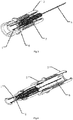
- Fig. 1 shows a view of the syringe of the first embodiment during an injection.
- Fig. 2 shows a view of the syringe of the first embodiment after the injection.
- Fig. 3 shows a part view of the syringe of the first embodiment during the injection.
- Fig. 4 shows a part view of the syringe of the first embodiment after the injection.
- the syringe of the first embodiment includes NEEDLE HOLDER 1, INNER SLIDING SLEEVE 2, OUTER SLIDING SLEEVE 3 AND PLUNGER 4.
- the NEEDLE HOLDER 1 is used for arranging INJECTING NEEDLE 5.
- the PLUNGER 4 which is used for adding liquid medicine into the NEEDLE HOLDER 1, is arranged on the opposite position with the NEEDLE HOLDER 1.
- the INNER SLIDING SLEEVE 2 is embedded in and connected to the OUTER SLIDING SLEEVE 3.
- the INNER SLIDING SLEEVE 2 and the OUTER SLIDING SLEEVE 3 can slide relatively to each other.
- the NEEDLE HOLDER 1 is embedded in and connected to the INNER SLIDING SLEEVE 2.
- the NEEDLE HOLDER 1 and the INNER SLIDING SLEEVE 2 can slide relatively to each other.
- the INNER SLIDING SLEEVE 2 and the OUTER SLIDING SLEEVE 3 slide to overlap the INNER SLIDING SLEEVE 2 and the OUTER SLIDING SLEEVE 3 outside the NEEDLE HOLDER 1. So that the INJECTING NEEDLE 5 can be exposed for the injection. After the injection, the INNER SLIDING SLEEVE 2 and the OUTER SLIDING SLEEVE 3 slide back. Then the INJECTING NEEDLE 5 is packed into the inner sliding sleeve 2 and the OUTER SLIDING SLEEVE 3.
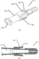
- Fig. 5 shows a perspective view of the needle holder of the first embodiment.
- Fig. 6 shows a side cross-sectional view of the needle holder of the first embodiment.
- the FIRST BULGE PART 101 and the ELASTIC EXTENDING PART 102 are arranged on the NEEDLE HOLDER 1.
- the FIRST BULGY PART 101 is arranged on the tail end of the NEEDLE HOLDER 1 through the ELASTIC EXTENDING PART 102.
- the FIRST GUIDING BULGE PART 103 which is matched with the first guiding groove of the INNER SLIDING SLEEVE 2, arranged on the NEEDLE HOLDER 1.
- the CHAMBER 104 is arranged in the NEEDLE HOLDER 1.
- Fig. 7 shows a perspective view of the inner sliding sleeve of the first embodiment.
- Fig. 8 shows a cross-sectional view of the inner sliding sleeve of the first embodiment.
- Fig. 9 shows a side cross-sectional view of the inner sliding sleeve of the first embodiment.
- the FIRST POSITIONING GROOVE 207 and the SECOND POSITIONING GROOVE 202 which are matched with the FIRST BULGE PART 101 of the NEEDLE HOLDER 1, are arranged on the INNER SLIDING SLEEVE 2.
- the FIRST POSITIONING GROOVE 207 is arranged on the head end of inside wall of the INNER SLIDING SLEEVE 2.
- a FIRST GUIDING GROOVE 203 which extends along with the INNER SLIDING SLEEVE 2, is arranged on inside wall of the INNER SLIDING SLEEVE 2.
- the FIRST GUIDING GROOVE 203 is matched with the FIRST GUIDING BULGE PART 103 of outside wall of the NEEDLE HOLDER 1.
- a FIRST SLOPE SURFACE 206 which is matched with the FIRST BULGE PART 101 of the NEEDLE HOLDER 1, is arranged on the edge of the tail end of inside wall of the INNER SLIDING SLEEVE 2.
- a SECOND BULGE PART 201 is arranged on the head end of the outside wall of the INNER SLIDING SLEEVE 2.
- Fig. 10 shows a perspective view of the outer sliding sleeve of the first embodiment.
- Fig. 11 shows a part cross-sectional view of the outer sliding sleeve of the first embodiment.
- Fig. 12 shows a side cross-sectional view of the outer sliding sleeve of the first embodiment.
- a THIRD POSITIONING GROOVE 301 and a FOURTH POSITIONING GROOVE 302 which are matched with the SECOND BULGE PART 201, are arranged on the OUTER SLIDING SLEEVE 3.
- the THIRD POSITIONING GROOVE 301 is arranged on the head end of inside wall of the OUTER SLIDING SLEEVE 3.
- the FOURTH POSITIONING GROOVE 302 is arranged on the tail end of inside wall of the OUTER SLIDING SLEEVE 3.
- a SECOND GUIDING GROOVE 304 which extends along with the OUTER SLIDING SLEEVE 3, is arranged on inside wall of the OUTER SLIDING SLEEVE 3.
- the SECOND GUIDING GROOVE 304 is matched with the SECOND GUIDING BULGE PART 204 of the INNER SLIDING SLEEVE 2.
- a SECOND HOLLOW STRUCTURE 305 forms inside the OUTER SLIDING SLEEVE 3.
- a SECOND SLOPE SURFACE 303 which is matched with the SECOND BULGE PART 201, is arranged on the edge of the tail end of inside wall of the OUTER SLIDING SLEEVE 3.
- a SECOND GUIDING BULGE PART 204 which is matched with the SECOND GUIDING GROOVE 304, is arranged on outside wall of the INNER SLIDING SLEEVE 2.
- the SECOND BULGE PART 201 is arranged on the head end of outside wall of the INNER SLIDING SLEEVE 2.
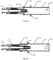
- Fig. 13 shows a part cross-sectional view of the connection between the needle holder and the inner sliding sleeve of the first embodiment.
- Fig. 14a-d respectively shows a side cross-sectional view of the connection between the needle holder and the inner sliding sleeve of the first embodiment.
- the FIRST BULGE PART 101 of the NEEDLE HOLDER 1 contacts with the first SLOPE SURFACE 206 of the INNER SLIDING SLEEVE 2, pushing the NEEDLE HOLDER 1 into the FIRST HOLLOW STRUCTURE 205 of the INNER SLIDING SLEEVE 2.
- the FIRST BULGE PART 101 is squeezed by the INNER SLIDING SLEEVE 2 through the ELASTIC EXTENDING PART 102 towards a center of the NEEDLE HOLDER 1.
- the FIRST BULGE PART 101 goes across the SECOND POSITIONING GROOVE 202. Rotating the NEEDLE HOLDER 1 around it's center axis line, so that the FIRST GUIDING BULGE PART 103 enters the FIRST POSITIONING GROOVE 207, and pushes the NEEDLE HOLDER 1 into the INNER SLIDING SLEEVE 2.
- the FIRST BULGY PART 101 enters the FIRST POSITIONING GROOVE 207, and the NEEDLE HOLDER 1 is fixed into the INNER SLIDING SLEEVE 2, so that the INNER SLIDING SLEEVE 2 overlaps with the NEEDLE HOLDER 1.
- the injection can be operated.
- Fig. 15 shows a part cross-sectional view of the connection among the needle holder, the inner sliding sleeve and the outer sliding sleeve of the first embodiment.
- Fig.16a-d respectively shows a side cross-sectional view of the connection among the needle holder, the inner sliding sleeve and the outer sliding sleeve of the first embodiment.
- the SECOND BULGE PART 201 of the INNER SLIDING SLEEVE 2 contacts with the SECOND BEVEL 303 of the OUTER SLIDING SLEEVE 3, pushing the INNER SLIDING SLEEVE 2 into the SECOND HOLLOW STRUCTURE 305 of the OUTER SLIDING SLEEVE 3, the SECOND BULGE PART 201 goes across the FOURTH POSITIONING GROOVE 302. Rotating the INNER SLIDING SLEEVE 2 around its center axis line.
- the SECOND GUIDING BULGE PART 204 enters the SECOND POSITIONING GROOVE 304 and pushes the INNER SLIDING SLEEVE 2 into the OUTER SLIDING SLEEVE 3.
- the SECOND BULGE PART 201 enters the THIRD POSITIONING GROOVE 301, and the INNER SLIDING SLEEVE 2 is fixed into the OUTER SLIDING SLEEVE 3, so that the NEEDLE HOLDER 1, the INNER SLIDING SLEEVE 2 and the OUTER SLIDING SLEEVE 3 overlap each other. Therefore the INJECTING NEEDLE 5 is exposed for the injection.
- the INJECTING NEEDLE 5 is packed into the INNER SLIDING SLEEVE 2 and the OUTER SLIDING SLEEVE 3, to avoid exposing the INJECTING NEEDLE 5 to the air or hurting someone's body by the INJECTING NEEDLE 5.
- Fig. 17 shows a perspective view of the needle holder and the piston of the first embodiment.
- Fig. 18 shows a side cross-sectional view of the piston of the first embodiment.
- the syringe of the embodiment also includes PISTON 6 with a liquid-guiding channel.
- the piston 6 is inserted into the CHAMBER 104 of the NEEDLE HOLDER 1.
- the liquid-guiding channel includes INJECTING CHANNEL 603, LIQUID-DIVERGING HOLE 602, and GUIDING CHANNEL 601, successively.
- the liquid flows through INJECTING CHANNEL 603, LIQUID-DIVERGING HOLE 602, and GUIDING CHANNEL 601, successively, and then the liquid is injected into a patient's body.
- the PISTON 6 can reduce the flow rate and the residue amount of the potion.
- Fig. 19 shows a part cross-sectional view of the connection among the needle holder, the inner sliding sleeve and the outer sliding sleeve of the second embodiment.
- Fig. 20 shows a side cross-sectional view of the connection between the inner sliding sleeve and the needle holder of the second embodiment.
- Fig. 21 shows a side cross-sectional view of the connection among the inner sliding sleeve, the outer sliding sleeve and the needle holder of the second embodiment.
- the structure of the syringe in the second embodiment is similar with the structure of the syringe in the first embodiment, expect for the following difference: a FIRST INNER SLIDING WALL 208 is arranged on the INNER SLIDING SLEEVE 2 and a SECOND INNER SLIDING WALL 307 is arranged on the OUTER SLIDING SLEEVE 3 in the second embodiment.
- a FIRST INNER SLIDING WALL 208 which is matched with the FIRST BULGE PART 101, is arranged on the inside wall of the INNER SLIDING SLEEVE 2.
- the FIRST INNER SLIDING WALL 208 is located at one side, towards the FIRST POSITIONING GROOVE 207, of the SECOND POSITIONING GROOVE 202.
- the height of the FIRST INNER SLIDING WALL 208 decreases gradually from the SECOND POSITIONING GROOVE 202 to the FIRST POSITIONING GROOVE 207.
- the angle between the FIRST INNER SLIDING WALL 208 and the inside wall of the INNER SLIDING SLEEVE 2 is greater than the angel between the THIRD INNER SLIDING WALL 209 and the inside wall of the INNER SLIDING SLEEVE 2.
- a SECOND INNER SLIDING WALL 307 which is matched with the SECOND BULGE PART 201, is arranged on the inside wall of the OUTER SLIDING SLEEVE 3, while the SECOND INNER SLIDING WALL 307 is located at the side, towards the THIRD POSITIONING GROOVE 301, of the FOURTH POSITIONING GROOVE 302. And the height of the SECOND INNER SLIDING WALL 307 decreases gradually from the THIRD POSITIONING GROOVE 301 to the FOURTH POSITIONING GROOVE 302.
- the angle between the SECOND INNER SLIDING WALL 307 and the inside wall of the OUTER SLIDING SLEEVE 3 is greater than the angle between the FOURTH INNER SLIDING WALL 308 and the inside wall of the OUTER SLIDING SLEEVE 3.
- Fig. 22 shows a part cross-sectional view of temporary positioning condition of the connection among the inner sliding sleeve, the outer sliding sleeve and the needle holder of the second embodiment.
- the first inner sliding wall 208 and the SECOND INNER SLIDING WALL 307 are used for fixing a temporary position before the injection.
- the INJECTING NEEDLE 5 may hurt someone if it is exposed to the air.
- the INNER SLIDING SLEEVE 2 and the OUTER SLIDING SLEEVE 3 can be slid, so that the FIRST BULGE PART 101 is pressed at the FIRST INNER SLIDING WALL 208, and the SECOND BULGE PART 201 is pressed at the SECOND INNER SLIDING WALL 307, so the INNER SLIDING SLEEVE 2 and the OUTER SLIDING SLEEVE 3 are fixed temporarily, meanwhile the injecting needle 5 is packed by the INNER SLIDING SLEEVE 2 and the OUTER SLIDING SLEEVE 3 together, avoiding hurting someone's body by the needle is exposed to the air.
- the first bulge part 101 is not in the SECOND POSITIONING GROOVE 202, and the second bulgy part 201 is not in the FOURTH POSITIONING GROOVE 302 either, thus the positions of the INNER SLIDING SLEEVE 2 and the OUTER SLIDING SLEEVE 3 are not fixed completely. If the medical worker begins the injection, the INNER SLIDING SLEEVE 2 and the OUTER SLIDING SLEEVE 3 slide towards an opposite direction of the direction of the injection, to expose INJECTING NEEDLE 5 to the air. Therefore, the injection can be continued.
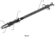
- Fig. 23 shows a view of the syringe of the third embodiment, as shown in the figure 23 , the syringe in the third embodiment includes NEEDLE HOLDER 1, INNER SLIDING SLEEVE 2 and PLUNGER 4.
- NEEDLE HOLDER 1 is used for arranging the NEEDLE 5.
- the PLUNGER 4 which is used for pushing liquid into the NEEDLE HOLDER 1, is arranged at the opposite position of the NEEDLE HOLDER 1.
- the NEEDLE HOLDER 1 is embedded in and connected to the INNER SLIDING SLEEVE 2, meanwhile NEEDLE HOLDER 1 and INNER SLIDING SLEEVE 2 can slide relatively to each other. Before the injection, the INNER SLIDING SLEEVE 2 slides, and the INNER SLIDING SLEEVE 2 and the NEEDLE HOLDER 1 are overlapped, to expose the INJECTING NEEDLE 5 for the injection.
- the INNER SLIDING SLEEVE 2 slides back, to pack the INJECTING NEEDLE 5 into the INNER SLIDING SLEEVE 2.
- the NEEDLE HOLDER 1 as shown in the figures 5 to 6 the INNER SLIDING SLEEVE 2 as shown in the figures 7 to 9 , and the PISTON 6 as shown in the figure 17 to 18 can be adopted for the syringe.
- the FIRST INNER SLIDING WALL as shown in the figures 19 to 20 can also be arranged on the INNER SLIDING SLEEVE 2.
- the syringe in the third embodiment is mainly provided for a shorter INJECTING NEEDLE 5.
- the shorter INJECTING NEEDLE 5 can be packed completely just by the INNER SLIDING SLEEVE 2. It is unnecessary to arrange the OUTER SLIDING SLEEVE. Therefore the syringe has a simplified structure and features materials saving.
Landscapes
- Health & Medical Sciences (AREA)
- Engineering & Computer Science (AREA)
- Heart & Thoracic Surgery (AREA)
- Vascular Medicine (AREA)
- Anesthesiology (AREA)
- Biomedical Technology (AREA)
- Hematology (AREA)
- Life Sciences & Earth Sciences (AREA)
- Animal Behavior & Ethology (AREA)
- General Health & Medical Sciences (AREA)
- Public Health (AREA)
- Veterinary Medicine (AREA)
- Environmental & Geological Engineering (AREA)
- Infusion, Injection, And Reservoir Apparatuses (AREA)
Applications Claiming Priority (2)
| Application Number | Priority Date | Filing Date | Title |
|---|---|---|---|
| CN201510002629.4A CN104906662B (zh) | 2015-01-05 | 2015-01-05 | 一种注射器 |
| PCT/CN2015/071070 WO2016109989A1 (fr) | 2015-01-05 | 2015-01-20 | Seringue |
Publications (2)
| Publication Number | Publication Date |
|---|---|
| EP3243541A1 true EP3243541A1 (fr) | 2017-11-15 |
| EP3243541A4 EP3243541A4 (fr) | 2018-08-22 |
Family
ID=54076361
Family Applications (1)
| Application Number | Title | Priority Date | Filing Date |
|---|---|---|---|
| EP15876497.7A Withdrawn EP3243541A4 (fr) | 2015-01-05 | 2015-01-20 | Seringue |
Country Status (6)
| Country | Link |
|---|---|
| EP (1) | EP3243541A4 (fr) |
| JP (1) | JP2018501006A (fr) |
| KR (1) | KR20170086581A (fr) |
| CN (2) | CN104906662B (fr) |
| BR (1) | BR112016028177A2 (fr) |
| WO (1) | WO2016109989A1 (fr) |
Families Citing this family (4)
| Publication number | Priority date | Publication date | Assignee | Title |
|---|---|---|---|---|
| CN106581824B (zh) * | 2016-08-16 | 2017-10-31 | 上海金塔医用器材有限公司 | 防针刺结构及包含其的注射针 |
| CN108670374B (zh) * | 2018-06-23 | 2023-12-05 | 南华大学 | 一种用于心血管的介入治疗装置 |
| CN111436951B (zh) * | 2020-03-04 | 2023-05-23 | 天津华鸿科技股份有限公司 | 采血针 |
| CN114768081B (zh) * | 2022-03-31 | 2023-08-22 | 重庆大学附属肿瘤医院 | 一种新型预充式导管冲洗器 |
Family Cites Families (19)
| Publication number | Priority date | Publication date | Assignee | Title |
|---|---|---|---|---|
| ATE19950T1 (de) * | 1982-12-20 | 1986-06-15 | Meditec Sa | Spritzampulle. |
| DE3801416C1 (en) * | 1988-01-20 | 1989-07-06 | Joerg Christoph 3000 Hannover De Odenthal | Protective device for a medical instrument with a cannula |
| US5098403A (en) * | 1989-12-05 | 1992-03-24 | Infusaid Inc. | Universal needle guard |
| US5338310A (en) * | 1992-02-06 | 1994-08-16 | Becton, Dickinson And Company | Needle device having safety indication features |
| US5984899A (en) * | 1993-02-11 | 1999-11-16 | Beech Medical Products, Inc. | Needle protector device having a lockable protective cover which is unlockable during actuation |
| JP3536847B2 (ja) * | 2002-07-09 | 2004-06-14 | 株式会社ジェイ・エム・エス | 誤穿刺防止用シールド付き医療用針装置 |
| CN1251772C (zh) * | 2003-10-30 | 2006-04-19 | 颜智远 | 自毁式注射器 |
| CN2706180Y (zh) * | 2004-04-19 | 2005-06-29 | 刘蓉娥 | 套控式安全型注射器 |
| CN1788805A (zh) * | 2004-12-17 | 2006-06-21 | 黄仲荣 | 具延伸保护盖针头结构 |
| CN1970105A (zh) * | 2005-11-22 | 2007-05-30 | 杨章民 | 一次用安全静脉留置针 |
| CN101041094A (zh) * | 2006-03-23 | 2007-09-26 | 许明正 | 可减少药液残留量的注射器 |
| CN201015668Y (zh) * | 2006-12-05 | 2008-02-06 | 张培伦 | 改进的注射器结构 |
| EP2578257A1 (fr) * | 2011-10-06 | 2013-04-10 | Sanofi-Aventis Deutschland GmbH | Dispositif de sécurité d'aiguille |
| EP2578260A1 (fr) * | 2011-10-07 | 2013-04-10 | Sanofi-Aventis Deutschland GmbH | Appareil pour injection intraoculaire |
| TW201336542A (zh) * | 2012-03-15 | 2013-09-16 | Ren-Yue Jang | 注射針頭之安全裝置 |
| CN202699781U (zh) * | 2012-07-02 | 2013-01-30 | 泛特生化科技股份有限公司 | 安全针头结构 |
| CN102974009B (zh) * | 2012-09-28 | 2015-02-04 | 林作钱 | 滑套式针头保护装置和安全注射器 |
| CN104056330B (zh) * | 2013-03-21 | 2016-08-24 | 许沛新 | 注射针器的防护装置 |
| CN204521826U (zh) * | 2015-01-05 | 2015-08-05 | 名高医疗器械(昆山)有限公司 | 一种注射器 |
-
2015
- 2015-01-05 CN CN201510002629.4A patent/CN104906662B/zh not_active Expired - Fee Related
- 2015-01-05 CN CN201810605256.3A patent/CN108939214A/zh active Pending
- 2015-01-20 EP EP15876497.7A patent/EP3243541A4/fr not_active Withdrawn
- 2015-01-20 BR BR112016028177A patent/BR112016028177A2/pt not_active Application Discontinuation
- 2015-01-20 WO PCT/CN2015/071070 patent/WO2016109989A1/fr not_active Ceased
- 2015-01-20 KR KR1020177016472A patent/KR20170086581A/ko not_active Ceased
- 2015-01-20 JP JP2017535702A patent/JP2018501006A/ja active Pending
Also Published As
| Publication number | Publication date |
|---|---|
| WO2016109989A1 (fr) | 2016-07-14 |
| BR112016028177A2 (pt) | 2017-08-22 |
| KR20170086581A (ko) | 2017-07-26 |
| JP2018501006A (ja) | 2018-01-18 |
| EP3243541A4 (fr) | 2018-08-22 |
| CN104906662A (zh) | 2015-09-16 |
| CN108939214A (zh) | 2018-12-07 |
| CN104906662B (zh) | 2019-03-12 |
Similar Documents
| Publication | Publication Date | Title |
|---|---|---|
| ES2681290T3 (es) | Conjunto de aguja intravenosa que tiene capacidades de dispensación de sangre | |
| KR102004938B1 (ko) | 카테터 장치 | |
| ES2749508T3 (es) | Jeringa de seguridad para recogida de sangre que tiene una aguja retráctil manualmente | |
| ES2740642T3 (es) | Dispositivo de inyección | |
| US10537688B2 (en) | Safety device for prefilled syringes | |
| ES2792927T3 (es) | Jeringa con profundidad de penetración ajustable | |
| US20110166528A1 (en) | Safety catheter | |
| KR20200037311A (ko) | 정맥 카테터 및 혈액 수집 장치 | |
| EP3243541A1 (fr) | Seringue | |
| US20130178807A1 (en) | Needle tip guard for intravenous catheter assembly | |
| EP2944346A1 (fr) | Aiguille à demeure veineuse sûre | |
| EP4691520A3 (fr) | Mécanisme d'activation pour dispositif d'administration de médicament et dispositif d'administration de médicament | |
| EP3181167A3 (fr) | Seringue à durée d'injection courte | |
| US11318255B2 (en) | Syringe with locking mechanism | |
| CN109475466B (zh) | 用于药剂输送装置的药剂容器保持架和组装药剂输送装置的方法 | |
| US20180014996A1 (en) | Self sheathing anesthetic needle with a dedicated syringe | |
| KR101536584B1 (ko) | 의료용 주사 바늘 및 이를 이용한 주사기 | |
| US10420878B2 (en) | Syringe assembly | |
| ES2207935T3 (es) | Dispositivo medico con aguja retractil. | |
| CN105246533B (zh) | 侧合并皮内适配器 | |
| US11110219B2 (en) | Syringe assembly | |
| US20080208120A1 (en) | Instrument for injections with retractable needle following use | |
| US11998423B2 (en) | Liquid administration tool | |
| KR20190074269A (ko) | 수축 가능한 주사기. | |
| MX2021008106A (es) | Protector telescopico para agujas con prevencion de exposicion a sangre. |
Legal Events
| Date | Code | Title | Description |
|---|---|---|---|
| PUAI | Public reference made under article 153(3) epc to a published international application that has entered the european phase |
Free format text: ORIGINAL CODE: 0009012 |
|
| 17P | Request for examination filed |
Effective date: 20160912 |
|
| AK | Designated contracting states |
Kind code of ref document: A1 Designated state(s): AL AT BE BG CH CY CZ DE DK EE ES FI FR GB GR HR HU IE IS IT LI LT LU LV MC MK MT NL NO PL PT RO RS SE SI SK SM TR |
|
| AX | Request for extension of the european patent |
Extension state: BA ME |
|
| DAX | Request for extension of the european patent (deleted) | ||
| A4 | Supplementary search report drawn up and despatched |
Effective date: 20180724 |
|
| RIC1 | Information provided on ipc code assigned before grant |
Ipc: A61M 5/32 20060101AFI20180716BHEP Ipc: A61M 5/178 20060101ALI20180716BHEP |
|
| STAA | Information on the status of an ep patent application or granted ep patent |
Free format text: STATUS: THE APPLICATION IS DEEMED TO BE WITHDRAWN |
|
| 18D | Application deemed to be withdrawn |
Effective date: 20190221 |