EP3243546A1 - Dispositif d'humidification, humidificateur et appareil de ventilation - Google Patents
Dispositif d'humidification, humidificateur et appareil de ventilation Download PDFInfo
- Publication number
- EP3243546A1 EP3243546A1 EP15876719.4A EP15876719A EP3243546A1 EP 3243546 A1 EP3243546 A1 EP 3243546A1 EP 15876719 A EP15876719 A EP 15876719A EP 3243546 A1 EP3243546 A1 EP 3243546A1
- Authority
- EP
- European Patent Office
- Prior art keywords
- liquid
- heating area
- outlet
- inlet pipeline
- liquid inlet
- Prior art date
- Legal status (The legal status is an assumption and is not a legal conclusion. Google has not performed a legal analysis and makes no representation as to the accuracy of the status listed.)
- Withdrawn
Links
Images


Classifications
-
- A—HUMAN NECESSITIES
- A61—MEDICAL OR VETERINARY SCIENCE; HYGIENE
- A61M—DEVICES FOR INTRODUCING MEDIA INTO, OR ONTO, THE BODY; DEVICES FOR TRANSDUCING BODY MEDIA OR FOR TAKING MEDIA FROM THE BODY; DEVICES FOR PRODUCING OR ENDING SLEEP OR STUPOR
- A61M16/00—Devices for influencing the respiratory system of patients by gas treatment, e.g. ventilators; Tracheal tubes
- A61M16/10—Preparation of respiratory gases or vapours
- A61M16/14—Preparation of respiratory gases or vapours by mixing different fluids, one of them being in a liquid phase
- A61M16/16—Devices to humidify the respiration air
- A61M16/162—Water-reservoir filling system, e.g. automatic
-
- A—HUMAN NECESSITIES
- A61—MEDICAL OR VETERINARY SCIENCE; HYGIENE
- A61M—DEVICES FOR INTRODUCING MEDIA INTO, OR ONTO, THE BODY; DEVICES FOR TRANSDUCING BODY MEDIA OR FOR TAKING MEDIA FROM THE BODY; DEVICES FOR PRODUCING OR ENDING SLEEP OR STUPOR
- A61M16/00—Devices for influencing the respiratory system of patients by gas treatment, e.g. ventilators; Tracheal tubes
- A61M16/10—Preparation of respiratory gases or vapours
- A61M16/1075—Preparation of respiratory gases or vapours by influencing the temperature
- A61M16/109—Preparation of respiratory gases or vapours by influencing the temperature the humidifying liquid or the beneficial agent
-
- A—HUMAN NECESSITIES
- A61—MEDICAL OR VETERINARY SCIENCE; HYGIENE
- A61M—DEVICES FOR INTRODUCING MEDIA INTO, OR ONTO, THE BODY; DEVICES FOR TRANSDUCING BODY MEDIA OR FOR TAKING MEDIA FROM THE BODY; DEVICES FOR PRODUCING OR ENDING SLEEP OR STUPOR
- A61M16/00—Devices for influencing the respiratory system of patients by gas treatment, e.g. ventilators; Tracheal tubes
-
- A—HUMAN NECESSITIES
- A61—MEDICAL OR VETERINARY SCIENCE; HYGIENE
- A61M—DEVICES FOR INTRODUCING MEDIA INTO, OR ONTO, THE BODY; DEVICES FOR TRANSDUCING BODY MEDIA OR FOR TAKING MEDIA FROM THE BODY; DEVICES FOR PRODUCING OR ENDING SLEEP OR STUPOR
- A61M16/00—Devices for influencing the respiratory system of patients by gas treatment, e.g. ventilators; Tracheal tubes
- A61M16/10—Preparation of respiratory gases or vapours
- A61M16/14—Preparation of respiratory gases or vapours by mixing different fluids, one of them being in a liquid phase
- A61M16/16—Devices to humidify the respiration air
- A61M16/162—Water-reservoir filling system, e.g. automatic
- A61M16/164—Water-reservoir filling system, e.g. automatic including a liquid inlet valve system
- A61M16/165—Water-reservoir filling system, e.g. automatic including a liquid inlet valve system with a float actuator
- A61M16/167—Water-reservoir filling system, e.g. automatic including a liquid inlet valve system with a float actuator acting vertically on the valve
-
- A—HUMAN NECESSITIES
- A61—MEDICAL OR VETERINARY SCIENCE; HYGIENE
- A61M—DEVICES FOR INTRODUCING MEDIA INTO, OR ONTO, THE BODY; DEVICES FOR TRANSDUCING BODY MEDIA OR FOR TAKING MEDIA FROM THE BODY; DEVICES FOR PRODUCING OR ENDING SLEEP OR STUPOR
- A61M2205/00—General characteristics of the apparatus
- A61M2205/36—General characteristics of the apparatus related to heating or cooling
- A61M2205/3653—General characteristics of the apparatus related to heating or cooling by Joule effect, i.e. electric resistance
Definitions
- the present disclosure relates to human respiratory regulation technologies, and more particularly, to a humidification device, a humidifier and a ventilator.
- a humidifier of a ventilator is mainly used for increasing humidity of air conveyed to a patient.
- the air for a medical purpose, generally does not contain adequate moisture. If the air is used directly, it may damage or irritate a respiratory tract or an upper respiratory tract of a user. Also, the respiratory tract or the upper respiratory tract of the user may be affected by dry and dense secreta of a bypass patient, which may cause airway constriction and even obstruction. By heating the moisture provided by the humidifier, the water vapor output of the humidifier may be increased.
- humidification devices of the existing humidifiers basically a water storage area and a heating area are integrated into one cavity.
- water sufficient to be consumed for a certain time is added to the humidification device.
- Moisture is slowly provided to the patient for use through airflow provided when the ventilator works and by heating.
- a technical problem to be solved by the present disclosure is to overcome deficiencies in the prior art such as the heating efficiency of a ventilator being relatively low when the amount of water in a humidification device is adequate.
- a humidification device which comprises a heating area and a liquid conveying device conveying liquid to the heating area.
- the liquid conveying device comprises a liquid inlet pipeline, the liquid inlet pipeline extends into the heating area and extends to a bottom of the heating area, and a reserved interval is provided between an outlet of the liquid inlet pipeline and the bottom of the heating area.
- the liquid conveying device further comprises an air outlet pipeline, an inlet of the liquid inlet pipeline is lower than an outlet of the air outlet pipeline, an outlet of the liquid inlet pipeline is lower than an inlet of the air outlet pipeline, and both the outlet of the liquid inlet pipeline and the inlet of the air outlet pipeline extend into the heating area.
- the liquid conveying device further comprises a suspension seal element arranged in the heating area, and the suspension seal element faces towards the outlet of the liquid inlet pipeline and may block off the outlet of the liquid inlet pipeline under a buoyancy action of the liquid in the heating area.
- the suspension seal element comprises a base part and a seal part arranged on the base part, and the seal part fits to the outlet of the liquid inlet pipeline.
- the seal part is at least partially positioned in the outlet of the liquid inlet pipeline.
- the liquid conveying device further comprises an elastic sealing element arranged in the heating area, and the elastic sealing element faces towards the outlet of the liquid inlet pipeline and may open the outlet of the liquid inlet pipeline under the action of air pressure.
- the elastic sealing element comprises a sealing plate and an elastic element arranged on a bottom of the sealing plate; a sealing member is arranged on the sealing plate facing towards the outlet of the liquid inlet pipeline, and the sealing member fits to the outlet of the liquid inlet pipeline.
- the humidification device further comprises a liquid storage area connected to the liquid conveying device, and the inlet of the liquid inlet pipeline is connected to the liquid storage area.
- the present disclosure further provides a humidifier, which comprises a heating element and the humidification device as mentioned above, wherein the heating element heats the liquid in the heating area of the humidification device.
- the present disclosure further provides a ventilator, which comprises a main machine and the humidifier as mentioned above, wherein the main machine is connected to an air inlet of the heating area, and a pipeline that may be connected to a human body is connected to an air outlet of the heating area.
- the humidification device can implement dynamic water supplementation, so that a constant amount of liquid in the heating area can be ensured, thereby avoiding dry burning.
- a liquid supplementing operation for the humidification device may be implemented by replacement or by supplementing liquid to the liquid storage area, so that the humidifier is prevented from being frequently opened or closed in a liquid adding process, and thus the humidifier is used very conveniently and efficiently. Furthermore, the heating element is not exposed in a liquid adding process, so that danger of a patient being scalded may be avoided.
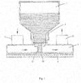
- the humidification device includes a heating area 3 and a liquid conveying device 2 conveying liquid (such as water or aqueous solution) to the heating area 3.
- the liquid conveying device 2 further may be configured to maintain the liquid in the heating area 3 at a preset volume.
- the liquid conveying device 2 comprises a liquid inlet pipeline 21, and the liquid inlet pipeline 21 extends into the heating area 3 and extends to a bottom of the heating area 3.
- a reserved interval is provided between an outlet 20, positioned in the heating area 3, of the liquid inlet pipeline 21 and a bottom of the heating area 3, so that after the liquid enters the heating area 3 from the liquid inlet pipeline 21, the liquid in the liquid inlet pipeline 21 stops flowing into the heating area 3 when a liquid level of the heating area 3 rises above an opening 20 of the liquid inlet pipeline 21 (at least is flush with the outlet 20 of the liquid inlet pipeline 21).
- the liquid inlet pipeline 21 may be straight or may be bent.
- the humidification device may further comprise a liquid storage area 1.
- the liquid storage area 1 having an opening may be detachably connected to the liquid conveying device 2, and is communicated with the heating area 3 via the liquid conveying device 2.
- the liquid storage area 1 is connected to the liquid conveying device 2 via the openings oppositely arranged.
- the opening of the liquid storage area 1 is smaller whereas the opening of the liquid conveying device 2 is larger.
- the opening of the liquid storage area 1 also may be directly sleeved in the opening of the liquid conveying device 2. As shown in FIG. 1 , the opening of the liquid storage area 1 which is filled with water is inserted into the opening of the liquid conveying device 2 by way of inverted insertion.
- the reserved interval is provided between the outlet 20, positioned in the heating area 3, of the liquid inlet pipeline 21 and a bottom surface of the heating area 3, so that the liquid inlet pipeline 21 does not contact the heating area 3, and thus the liquid in the liquid conveying device 2 can enter the heating area 3 from the outlet 20 of the liquid inlet pipeline 21 conveniently.
- the reserved interval is greater than 5mm and smaller than 30mm.
- the reserved interval is greater than 5mm, which can allow the liquid in the liquid inlet pipeline 21 to flow out smoothly.
- the reserved interval is smaller than 30mm to reduce the amount of liquid in the heating area, so that the liquid in the heating area evaporates more quickly under a heating condition of the same power, and thus the humidification effect is better.
- the reserved interval is 10mm or 15mm, which may provide the best humidification effect.
- the outlet 20 of the liquid inlet pipeline 21 is arranged on an end portion of the heating area 3.
- the outlet 20 also may be arranged on other portions instead of the end portion, positioned in the heating area 3, of the liquid inlet pipeline 21.
- the liquid in the liquid storage area 1 may flow into the heating area 3 via the liquid conveying device 2 under the action of gravity.
- the heating area 3 is provided with an air inlet 31 and an air outlet 32.
- the air inlet 31 is configured to guide outside air (air outputted from the ventilator) to enter the heating area 3 for humidification, and the air after being humidified enters, via the air outlet 32, a pipeline connected to a nasal cavity and/or an oral cavity of a user, so that the air is conveyed to the user.
- Arrows in FIG. 1 indicate an airflow direction indicating that the air enters from the air inlet 31, and flows out from the air outlet 32 via the heating area 3.
- the liquid in the liquid storage area 1 enters the heating area 3 via the liquid conveying device 2, and simultaneously, the air in the heating area 3 enters the liquid storage area 1 via the liquid conveying device 2, so that the liquid in the liquid storage area 1 may automatically enter the heating area 3 under the action of gravity. As the liquid in the liquid storage area 1 continuously enters the heating area 3, the liquid level of the heating area 3 may gradually rise.
- the liquid level of the heating area 3 rises above the outlet 20 of the liquid inlet pipeline 21, positioned in the heating area 3, of the liquid conveying device 2 (the liquid level of the heating area 3 at least is flush with the outlet 20 of the liquid inlet pipeline 21), the air in the heating area 3 cannot continuously enter the liquid storage area 1 via the liquid conveying device 2, so that the liquid in the liquid storage area 1 cannot be continuously supplemented to the heating area 3, and thus the liquid in the heating area 3 can be maintained at the preset volume.
- the liquid in the heating area 3 After being heated, the liquid in the heating area 3 is conveyed to the user together with the air via the air outlet 32 so that the liquid in the heating area 3 is consumed, and a gap generated between the liquid level of the heating area 3 and the outlet 20, positioned in the heating area 3, of the liquid conveying device 2 allows the air to enter the liquid conveying device 2 and finally reach to the liquid storage area 1, the liquid in the liquid storage area 1 is supplemented to the heating area 3 continuously under the action of gravity. That is, the liquid in the liquid storage area 1 being supplemented to the heating area 3 is a dynamic balancing process.
- the liquid in the liquid storage area 1 When the liquid in the liquid storage area 1 is supplemented to the heating area 3 via the liquid conveying device 2 endlessly so that the liquid level of the heating area 3 gradually rises above the outlet 20 of the liquid inlet pipeline 21 (the liquid level of the heating area 3 at least is flush with the outlet 20 of the liquid inlet pipeline 21), the liquid in the liquid storage area 1 stops flowing into the heating area 3 under the action of the atmospheric pressure and thus the liquid in the heating area 3 is maintained at the preset volume.
- the liquid in the heating area 3 As the liquid in the heating area 3 is consumed (the liquid enters, via the air outlet 32 together with the air entering the heating area 3, the pipeline connected to the nasal cavity and/or the oral cavity of the user), when the liquid level of the heating area 3 is lower than the outlet 20 of the liquid inlet pipeline 21, the liquid in the liquid storage area 1 is supplemented to the heating area 3 under the action of gravity, till the liquid level of the heating area 3 rises above the outlet 20 of the liquid inlet pipeline 21 or the liquid in the liquid storage area 1 is used up.
- a sectional area of the outlet 20 of the liquid inlet pipeline 21 may be a circle or an oval, or may be a polygon such as triangle or rectangle, and further may be an irregular shape. To ensure that the liquid conveying device 2 may supplement the liquid to the heating area 3 smoothly in time, the sectional area of the outlet 20 of the liquid inlet pipeline 21 is greater than 7mm 2 in some embodiments of the present disclosure.
- the air in the heating area 3 needs to enter the liquid storage area 1 from the heating area 3 reversely via the liquid conveying device 2.
- the air may enter the liquid storage area 1 upward by way of bubbles, and the liquid in the liquid storage area 1 enters the heating area 3 along with gurgling sound.
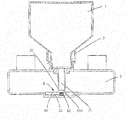
- FIG. 2 illustrates the humidification device according to a second embodiment of the present disclosure.
- the liquid conveying device 2 comprises the liquid inlet pipeline 21 and the air outlet pipeline 22.
- the liquid inlet pipeline 21 is configured to convey the liquid in the liquid storage area 1 to the heating area 3
- the air outlet pipeline 22 is configured to convey the air in the heating area 3 to the liquid storage area 1.
- Both an outlet 211 of the liquid inlet pipeline 21 and an inlet 221 of the air outlet pipeline 22 extend into the heating area 3, the inlet 212 of the liquid inlet pipeline 21 is lower than the outlet 222 of the air outlet pipeline 22, the outlet 211 of the liquid inlet pipeline 21 is lower than the inlet 221 of the air outlet pipeline and is closer to a bottom of the heating area 3 than the inlet 221 of the air outlet pipeline.
- the air outlet pipeline 22 may be straight or may be bent.
- the liquid in the liquid storage area 1 may enter the heating area 3 via the liquid inlet pipeline 21 and the air in the heating area 3 may enter the liquid storage area 1 from the air outlet pipeline 22, so as to keep balance of pressure in the liquid storage area 1 and the heating area 3.
- the air in the heating area 3 may enter the liquid storage area 1 via the air outlet pipeline 22, the liquid in the liquid storage area 1 may flow into the heating area 3 via the liquid inlet pipeline 21, and thus the liquid level in the heating area 3 rises above the inlet 221 of the air outlet pipeline 22 (the liquid level of the heating area at least is flush with the inlet 221 of the air outlet pipeline 22).
- the liquid in the liquid storage area 1 stops flowing into the heating area 3, so that the liquid in the heating area 3 is maintained at the preset volume.
- the liquid in the liquid storage area 1 may enter the heating area 3 via the liquid inlet pipeline 21 and the air outlet pipeline 222.
- the air in the heating area 3 enters the liquid storage area 1 via the air outlet pipeline 22.
- the liquid in the liquid storage area 1 stops flowing into the heating area 3 via the liquid inlet pipeline 21, and thus the liquid in the heating area 3 can be maintained at the preset volume.
- FIG. 3 illustrates the humidification device according to a third embodiment of the present disclosure.
- a suspension seal element 5 which may block off the outlet 20, positioned in the heating area 3, of the liquid inlet pipeline 21 in the liquid conveying device 2, is arranged in the heating area 3.
- a density of the suspension seal element 5 is smaller than that of the liquid, and is arranged directly facing the outlet 20 of the liquid inlet pipeline 21.
- the suspension seal element 5 When there is no liquid in the heating area 3, the suspension seal element 5 contacts the bottom surface of the heating area 3, and is separated from the outlet 20 of the liquid inlet pipeline 21. Consequently, the liquid in the liquid storage area 1 may flow into the heating area 3 via the liquid inlet pipeline 21. As the water continuously enters the heating area 3, the suspension seal element 5 whose density is lower than that of the water liquid gradually rises as the liquid level rises until the outlet 20 of the liquid inlet pipeline 21 is sealed up and thus the liquid in the liquid storage area 1 stops flowing into the heating area 3. When the amount of the liquid in the heating area 3 is gradually reduced, the suspension seal element 5 gradually drops as the liquid level drops. At this moment, the suspension seal element 5 is separated from the outlet 20 of the liquid inlet pipeline 21 again and thus the liquid in the liquid storage area 1 flows into the heating area 3 again.
- a seal structure is arranged on a top, facing towards the liquid storage area 1, of the suspension seal element 5, so as to correspond to the outlet 20 of the liquid inlet pipeline 21.
- the suspension seal element 5 comprises a base part 51 and a seal part 52 (i.e., the above-mentioned seal structure) on the base part 51.
- the seal part 52 is sleeved in the outlet 20 of the liquid inlet pipeline 21, or at least a part of the seal part 52 is sleeved in the outlet 20 of the liquid inlet pipeline 21.
- An external shape of the seal part 52 fits to an internal shape of the outlet 20 of the liquid inlet pipeline 21.
- a spherical crown namely a spherical seal part, is correspondingly arranged on the suspension seal element 5.
- the spherical crown on the suspension seal element 5 precisely blocks off the circular outlet 20 of the liquid inlet pipeline 21.
- an overall height of the suspension seal element 5, namely the sum of the height of the base part 51 and the height of the seal part 52, is greater than a distance from the outlet 20 of the liquid inlet pipeline 21 to the bottom surface of the heating area 3.
- the height of the base part 51 of the suspension seal element 5 is smaller than the distance from the outlet 20 of the liquid inlet pipeline 21 to the bottom surface of the heating area 3.
- the suspension seal element 5 may only have a gap from the liquid inlet pipeline 21 but may not be completely separated from the liquid inlet pipeline 21. Therefore, it is avoided that the outlet 20 of the liquid inlet pipeline 21 cannot be sealed up subsequently when there is liquid in the heating area 3 because the suspension seal element 5 is completely separated from the outlet 20 of the liquid inlet pipeline 21 due to shortage of liquid in the heating area 3.
- FIG. 4 illustrates the humidification device according to a fourth embodiment of the present disclosure.
- the heating area 3 is provided with an elastic sealing element 6, which may block off the outlet 29 of the liquid inlet pipeline 21, under the outlet 22 of the liquid inlet pipeline 21 of the liquid conveying device 2.
- the elastic sealing element 6 comprises a sealing plate 61 and an elastic element 62 arranged at a bottom of the sealing plate.
- the sealing plate 61 faces towards the outlet 29 of the liquid inlet pipeline 21, and the elastic element 62 props against between the bottom of the sealing plate 61 and the bottom of the heating area 3.
- the sealing plate 61 is provided with a sealing member 610, and the external shape of the sealing member 610 fits to the internal shape of the outlet 20 of the liquid inlet pipeline 21, so that the sealing member 610 can block off the outlet 20 of the liquid inlet pipeline 21.
- the elastic element 62 may be, for example, a spring.
- the heating area 3 is provided with a cavity 33 corresponding to the elastic sealing element 6.
- the sealing plate 61 in the elastic sealing element 6 fits to the cavity 33.
- the elastic element 62 is arranged in the cavity 33.
- the air generated by the ventilator passes through the heating area 3 so that humid air is conveyed to the patient.
- the air mainly passes from a side, facing towards the outlet 20 of the liquid inlet pipeline 21, of the sealing plate 61, so that the sealing plate 61 is pressed downward, and the spring is stressed and compressed to drive the sealing member 610 on the sealing plate 61 to separate from the outlet 20 of the liquid inlet pipeline 21, and at this moment, the water in the liquid inlet pipeline 21 enters the heating area 3.
- the sealing plate 61 When the density of the sealing plate 61 is smaller than that of the liquid, as the liquid enters the heating area 3 continuously, the sealing plate 61 gradually rises as the liquid level rises until the outlet 20 of the liquid inlet pipeline 21 is sealed up and thus the liquid in the liquid storage area 1 stops flowing into the heating area 3.
- the elastic sealing element 6 When the amount of the liquid in the heating area 3 gradually reduces, the elastic sealing element 6 gradually drops as the liquid level drops. At this moment, the elastic sealing element 6 is separated from the outlet 20 of the liquid inlet pipeline 21 again, and thus the liquid in the liquid storage area 1 starts flowing into the heating area 3 again.
- the sealing plate 61 When the density of the sealing plate 61 is greater than that of the liquid, and when the liquid level of the heating area 3 is about to rise above the sealing plate 61, under the combined action of a buoyancy force of the liquid and a spring force, the sealing plate 61 may be driven to block off the outlet 20 of the liquid inlet pipeline 21, and thus the liquid in the liquid storage area 1 stops supplementing to the heating area 3.
- the humidification device of the humidifier is divided into two cavities, namely the liquid storage area and the heating area.
- the liquid storage area and the heating area are communicated via a liquid conveying device, and the liquid level height of the heating area is controlled by controlling the distance between the outlet of the liquid inlet pipeline in the liquid conveying device and the bottom surface of the heating area. In this way, the total amount of the liquid in the heating area is reduced, and thus the heating efficiency is improved and the heating time is shortened.
- the liquid adding operation may be implemented, and it is unnecessary to take out the liquid conveying device, the heating area, and the heating element. Therefore, the humidifier is prevented from being frequently opened or closed in the liquid adding process, and thus the humidifier is used conveniently and efficiently.
- a certain amount of water still may be stored in the heating area to humidify the air, thereby avoiding a phenomenon of dry burning and a danger of the device being overheated due to failure of adding the liquid in time.
- the heating element is not exposed in the water adding process, so that the danger of the patient being scalded may be avoided.
- a dynamic balance may be maintained between the liquid and the air in the liquid storage area 1 and the liquid and the air in the heating area 3 under the control action of intercommunication of the fluid conveying device 2 and fluid (comprising the liquid and the air) flow.
- the liquid in the liquid storage area 1 may be continuously supplemented to the heating area 3 until the liquid in the liquid storage area 1 is used up.
- the user may replace the liquid storage area 1 or take the liquid storage area 1 down and then fill the liquid storage area 1 with the liquid for use again.
- pressures of the air inlet 31 and the air outlet 32 of the heating area 3 are relatively constant, so that the air pressure in the heating area 3 is relatively constant.
- the liquid storage area 1, the heating area 3 and the liquid conveying device 2 form into a sealing member.
- a reserved interval is provided between the outlet 20 of the liquid inlet pipeline 21 and the bottom of the heating area 3, so that after the liquid enters the heating area 3 from the liquid inlet pipeline 21, the liquid in the liquid inlet pipeline 21 stops flowing into the heating area 3 when the liquid level of the heating area 3 rises above the opening 20 of the liquid inlet pipeline 21 (at least is flush with the outlet 20 of the liquid inlet pipeline 21).
- the humidifier according to the embodiment of the present disclosure comprises a heating element and the humidification device provided in the above embodiments.
- the heating element is mainly configured to heat the liquid in the heating area 3. As shown in FIG. 1 , preferably, the heating element is positioned at the bottom of the heating area 3, so that the water in the heating area 3 may be heated more uniformly.
- the heating element is configured to generate heat to heat the liquid in the heating area 3.
- the heating element is designed as a heating bottom plate 4 positioned at the bottom of the heating area 3 and directly contacting the bottom of the heating area 3.
- the bottom of the heating area 3 has good heat conductivity, and thus may efficiently conduct the heat generated by the heating element to the liquid in the heating area 3.
- the heating element and the corresponding heating area 3 arranged in such a way may guarantee a higher heating efficiency.
- the ventilator according the embodiment of the present disclosure comprises a main machine and the humidifier as mentioned above.
- the main machine is connected to the air inlet of the heating area.
- a pipeline connected to a human body is connected to the air outlet of the heating area.
Landscapes
- Health & Medical Sciences (AREA)
- Emergency Medicine (AREA)
- Pulmonology (AREA)
- Engineering & Computer Science (AREA)
- Anesthesiology (AREA)
- Biomedical Technology (AREA)
- Heart & Thoracic Surgery (AREA)
- Hematology (AREA)
- Life Sciences & Earth Sciences (AREA)
- Animal Behavior & Ethology (AREA)
- General Health & Medical Sciences (AREA)
- Public Health (AREA)
- Veterinary Medicine (AREA)
- Air Humidification (AREA)
Applications Claiming Priority (2)
| Application Number | Priority Date | Filing Date | Title |
|---|---|---|---|
| CN201510012049.3A CN104548308B (zh) | 2015-01-09 | 2015-01-09 | 一种加湿装置、湿化器及呼吸机 |
| PCT/CN2015/100055 WO2016110219A1 (fr) | 2015-01-09 | 2015-12-31 | Dispositif d'humidification, humidificateur et appareil de ventilation |
Publications (2)
| Publication Number | Publication Date |
|---|---|
| EP3243546A1 true EP3243546A1 (fr) | 2017-11-15 |
| EP3243546A4 EP3243546A4 (fr) | 2018-05-16 |
Family
ID=53066058
Family Applications (1)
| Application Number | Title | Priority Date | Filing Date |
|---|---|---|---|
| EP15876719.4A Withdrawn EP3243546A4 (fr) | 2015-01-09 | 2015-12-31 | Dispositif d'humidification, humidificateur et appareil de ventilation |
Country Status (4)
| Country | Link |
|---|---|
| US (1) | US10758702B2 (fr) |
| EP (1) | EP3243546A4 (fr) |
| CN (1) | CN104548308B (fr) |
| WO (1) | WO2016110219A1 (fr) |
Families Citing this family (10)
| Publication number | Priority date | Publication date | Assignee | Title |
|---|---|---|---|---|
| CN104548308B (zh) | 2015-01-09 | 2019-03-12 | 北京怡和嘉业医疗科技股份有限公司 | 一种加湿装置、湿化器及呼吸机 |
| CN107174718B (zh) * | 2017-06-21 | 2024-05-24 | 湖南明康中锦医疗科技发展有限公司 | 一种呼吸机湿化器及呼吸湿化治疗装置 |
| CN111388834B (zh) * | 2020-01-21 | 2023-12-05 | 湖南明康中锦医疗科技发展有限公司 | 一种用于呼吸支持设备的湿化装置 |
| CN111494775A (zh) * | 2020-04-26 | 2020-08-07 | 北京怡和嘉业医疗科技股份有限公司 | 湿化器及通气治疗设备 |
| CN112274754A (zh) * | 2020-09-15 | 2021-01-29 | 湖南明康中锦医疗科技发展有限公司 | 一种呼吸支持设备的湿化装置 |
| CN114642812A (zh) * | 2020-12-18 | 2022-06-21 | 广州和普乐健康科技有限公司 | 一种便携式湿化器 |
| US11560665B2 (en) * | 2020-12-21 | 2023-01-24 | Conair Llc | Handheld appliance |
| USD966636S1 (en) | 2020-12-21 | 2022-10-11 | Conair Llc | Handheld steam appliance with refilling cradle |
| CN112755358B (zh) * | 2021-01-23 | 2023-05-16 | 浙江百获健康科技有限公司 | 一种氧气湿化装置及氧气湿化液袋 |
| WO2022251898A1 (fr) * | 2021-06-04 | 2022-12-08 | Quangang Yang | Dispositif d'assistance respiratoire |
Family Cites Families (23)
| Publication number | Priority date | Publication date | Assignee | Title |
|---|---|---|---|---|
| GB1294809A (en) * | 1971-08-23 | 1972-11-01 | Philips Electronic Associated | Gas humidifier for a medical respirator |
| US3757082A (en) | 1972-01-21 | 1973-09-04 | Critical Care Systems Inc | Humidifier and heater for delicered gases |
| US4051205A (en) * | 1972-09-13 | 1977-09-27 | Graham Cameron Grant | Apparatus for saturated gas delivery |
| GB1450097A (en) * | 1973-09-06 | 1976-09-22 | Respiratory Care | Humidifier method and apparatus for printing |
| CH576791A5 (fr) | 1974-03-28 | 1976-06-30 | Hoffmann La Roche | |
| US4225542A (en) | 1978-12-12 | 1980-09-30 | Minnesota Mining And Manufacturing Company | Evaporative humidifier |
| US4926856A (en) * | 1985-06-21 | 1990-05-22 | Hudson Oxygen Therapy Sales Company | Feeding system |
| US5943473A (en) * | 1997-05-29 | 1999-08-24 | Levine; Walter | Heated cartridge humidifier |
| US6988497B2 (en) * | 2002-09-18 | 2006-01-24 | Medex Cardio-Pulmonary, Inc. | Apparatus for equalizing air pressure in air respiratory system |
| US20080054497A1 (en) * | 2006-08-31 | 2008-03-06 | Medex Cardio-Pulmonary, Inc.. | Vented cap humidification system |
| US7722016B2 (en) * | 2006-08-31 | 2010-05-25 | Medex Cardio-Pulmonary, Inc. | Float for humidification chamber |
| EP2168403B1 (fr) * | 2007-06-05 | 2021-02-17 | ResMed Pty Ltd | Radiateur électrique à application spécifique pour humidification et réchauffage de fumées |
| CN101780301A (zh) * | 2009-01-15 | 2010-07-21 | 崇仁科技事业股份有限公司 | 潮湿加热罐 |
| DE102009011137A1 (de) | 2009-03-03 | 2010-09-09 | Seleon Gmbh | Verdunstungskammer, Zwischenkammer sowie Verfahren |
| EP2319568B1 (fr) * | 2009-11-06 | 2013-05-29 | Arta Plast Ab | Dispositif d'humidification d'air inhalé pour la respiration artificielle |
| CN201768248U (zh) * | 2010-09-08 | 2011-03-23 | 新利虹科技股份有限公司 | 加湿器及使用该加湿器的呼吸装置 |
| CN203898892U (zh) * | 2014-06-13 | 2014-10-29 | 湖南省人民医院 | 一种呼吸机湿化罐 |
| CN104548307B (zh) * | 2015-01-09 | 2017-12-22 | 北京怡和嘉业医疗科技股份有限公司 | 一种加湿装置、湿化器及呼吸机 |
| CN104548308B (zh) * | 2015-01-09 | 2019-03-12 | 北京怡和嘉业医疗科技股份有限公司 | 一种加湿装置、湿化器及呼吸机 |
| CN204446900U (zh) * | 2015-01-09 | 2015-07-08 | 北京怡和嘉业医疗科技有限公司 | 一种加湿装置、湿化器及呼吸机 |
| CN104548298B (zh) * | 2015-01-09 | 2017-11-14 | 北京怡和嘉业医疗科技股份有限公司 | 一种呼吸机 |
| CN104548299B (zh) * | 2015-01-09 | 2017-05-24 | 北京怡和嘉业医疗科技有限公司 | 一种呼吸机及湿化器 |
| CN204446899U (zh) * | 2015-01-09 | 2015-07-08 | 北京怡和嘉业医疗科技有限公司 | 一种水罐、湿化器及呼吸机 |
-
2015
- 2015-01-09 CN CN201510012049.3A patent/CN104548308B/zh active Active
- 2015-12-31 US US15/542,440 patent/US10758702B2/en active Active
- 2015-12-31 EP EP15876719.4A patent/EP3243546A4/fr not_active Withdrawn
- 2015-12-31 WO PCT/CN2015/100055 patent/WO2016110219A1/fr not_active Ceased
Also Published As
| Publication number | Publication date |
|---|---|
| WO2016110219A1 (fr) | 2016-07-14 |
| CN104548308B (zh) | 2019-03-12 |
| CN104548308A (zh) | 2015-04-29 |
| EP3243546A4 (fr) | 2018-05-16 |
| US20180021539A1 (en) | 2018-01-25 |
| US10758702B2 (en) | 2020-09-01 |
Similar Documents
| Publication | Publication Date | Title |
|---|---|---|
| US10758702B2 (en) | Humidification device, humidifier and ventilator | |
| CN215995219U (zh) | 一种湿化器及通气治疗设备 | |
| CN103800981B (zh) | 用于呼吸机的加湿器以及包含其的呼吸机 | |
| CN104548298B (zh) | 一种呼吸机 | |
| CN204446900U (zh) | 一种加湿装置、湿化器及呼吸机 | |
| EP3243545B1 (fr) | Dispositif d'humidification, humidificateur et appareil de ventilation | |
| CN111388834A (zh) | 一种用于呼吸支持设备的湿化装置 | |
| CN204446853U (zh) | 一种呼吸机 | |
| CN203763626U (zh) | 用于呼吸机的加湿器以及呼吸机 | |
| CN116440379A (zh) | 一种呼吸机用的湿化加热器 | |
| CN102671275A (zh) | 加湿设备和具有该加湿设备的通气治疗设备 | |
| CN116764062A (zh) | 用于制氧机的恒温恒湿水杯以及包含其的制氧机 | |
| CN203971125U (zh) | 一种呼吸机用自动注水湿化罐 | |
| CN221535305U (zh) | 一种多功能制氧机 | |
| CN202654514U (zh) | 加湿设备和具有该加湿设备的通气治疗设备 | |
| CN219743623U (zh) | 一种icu用氧气加湿装置 | |
| CN204446898U (zh) | 一种加湿装置、湿化器及呼吸机 | |
| CN119185726A (zh) | 一种呼吸机湿化罐防烧干装置 | |
| CN218129527U (zh) | 一种主动加热吸入式呼吸机湿化器部件 | |
| CN201954698U (zh) | 防泄漏加湿器 | |
| CN211214872U (zh) | 一种呼吸机湿化罐 | |
| CN214912287U (zh) | 一种重力球引流式氧气湿化通气管 | |
| CN212662438U (zh) | 一种用于呼吸支持设备的湿化装置 | |
| CN211050629U (zh) | 一种壁挂式高流量氧疗加湿装置 | |
| CN107050615A (zh) | 一种湿化器及其自动加水的湿化盒 |
Legal Events
| Date | Code | Title | Description |
|---|---|---|---|
| PUAI | Public reference made under article 153(3) epc to a published international application that has entered the european phase |
Free format text: ORIGINAL CODE: 0009012 |
|
| 17P | Request for examination filed |
Effective date: 20170731 |
|
| AK | Designated contracting states |
Kind code of ref document: A1 Designated state(s): AL AT BE BG CH CY CZ DE DK EE ES FI FR GB GR HR HU IE IS IT LI LT LU LV MC MK MT NL NO PL PT RO RS SE SI SK SM TR |
|
| AX | Request for extension of the european patent |
Extension state: BA ME |
|
| RIC1 | Information provided on ipc code assigned before grant |
Ipc: A61M 16/10 20060101ALI20171218BHEP Ipc: A61M 16/16 20060101AFI20171218BHEP Ipc: A61M 16/00 20060101ALN20171218BHEP |
|
| DAV | Request for validation of the european patent (deleted) | ||
| DAX | Request for extension of the european patent (deleted) | ||
| A4 | Supplementary search report drawn up and despatched |
Effective date: 20180416 |
|
| RIC1 | Information provided on ipc code assigned before grant |
Ipc: A61M 16/00 20060101ALN20180410BHEP Ipc: A61M 16/10 20060101ALI20180410BHEP Ipc: A61M 16/16 20060101AFI20180410BHEP |
|
| STAA | Information on the status of an ep patent application or granted ep patent |
Free format text: STATUS: THE APPLICATION IS DEEMED TO BE WITHDRAWN |
|
| 18D | Application deemed to be withdrawn |
Effective date: 20181120 |