EP3243576B1 - Dispositif de traitement l'interieur de tuyaux non accessibles et de tuyauterie a l'aide de projection de jet haute pression d'un fluide - Google Patents
Dispositif de traitement l'interieur de tuyaux non accessibles et de tuyauterie a l'aide de projection de jet haute pression d'un fluide Download PDFInfo
- Publication number
- EP3243576B1 EP3243576B1 EP16168758.7A EP16168758A EP3243576B1 EP 3243576 B1 EP3243576 B1 EP 3243576B1 EP 16168758 A EP16168758 A EP 16168758A EP 3243576 B1 EP3243576 B1 EP 3243576B1
- Authority
- EP
- European Patent Office
- Prior art keywords
- nozzle
- pipe wall
- pipe
- jet
- parallel
- Prior art date
- Legal status (The legal status is an assumption and is not a legal conclusion. Google has not performed a legal analysis and makes no representation as to the accuracy of the status listed.)
- Active
Links
Images


Classifications
-
- B—PERFORMING OPERATIONS; TRANSPORTING
- B08—CLEANING
- B08B—CLEANING IN GENERAL; PREVENTION OF FOULING IN GENERAL
- B08B9/00—Cleaning hollow articles by methods or apparatus specially adapted thereto
- B08B9/02—Cleaning pipes or tubes or systems of pipes or tubes
- B08B9/027—Cleaning the internal surfaces; Removal of blockages
-
- B—PERFORMING OPERATIONS; TRANSPORTING
- B08—CLEANING
- B08B—CLEANING IN GENERAL; PREVENTION OF FOULING IN GENERAL
- B08B9/00—Cleaning hollow articles by methods or apparatus specially adapted thereto
- B08B9/02—Cleaning pipes or tubes or systems of pipes or tubes
- B08B9/027—Cleaning the internal surfaces; Removal of blockages
- B08B9/04—Cleaning the internal surfaces; Removal of blockages using cleaning devices introduced into and moved along the pipes
- B08B9/043—Cleaning the internal surfaces; Removal of blockages using cleaning devices introduced into and moved along the pipes moved by externally powered mechanical linkage, e.g. pushed or drawn through the pipes
- B08B9/0433—Cleaning the internal surfaces; Removal of blockages using cleaning devices introduced into and moved along the pipes moved by externally powered mechanical linkage, e.g. pushed or drawn through the pipes provided exclusively with fluid jets as cleaning tools
-
- B—PERFORMING OPERATIONS; TRANSPORTING
- B08—CLEANING
- B08B—CLEANING IN GENERAL; PREVENTION OF FOULING IN GENERAL
- B08B9/00—Cleaning hollow articles by methods or apparatus specially adapted thereto
- B08B9/02—Cleaning pipes or tubes or systems of pipes or tubes
- B08B9/027—Cleaning the internal surfaces; Removal of blockages
- B08B9/04—Cleaning the internal surfaces; Removal of blockages using cleaning devices introduced into and moved along the pipes
- B08B9/049—Cleaning the internal surfaces; Removal of blockages using cleaning devices introduced into and moved along the pipes having self-contained propelling means for moving the cleaning devices along the pipes, i.e. self-propelled
- B08B9/0495—Nozzles propelled by fluid jets
Definitions
- the invention relates to a device for processing the interior of inaccessible pipes and pipe networks by means of high-pressure jets of a fluid with or without an abrasive.
- a corresponding device for cleaning pipes is in the DE 196 26 590 A1 disclosed. This device consists of a transport device and a rotating nozzle device. In order to avoid damage to the inner wall of the pipe due to a standstill of the rotary nozzle, an additional rotational movement of the nozzle arrangement is provided.
- the guide elements can also be designed to be collapsible in order to enable adaptation to different pipe diameters.
- a minimal distance between the nozzle arrangement and the inner wall of the pipe is aimed for.
- an angle of the high pressure jet that deviates from 90 ° to the inner wall of the pipe is desired.
- a device for processing channel walls of closed channels by means of high-pressure liquid jets is from the EP 2 891 526 A1 known.
- the device has a nozzle body with at least one jet nozzle, which is arranged at the front end of the device and for Generation of a forward directed, focused jet of a liquid jet medium is suitable.
- the alignment of the beam "forwards" includes that the beam direction coincides with the channel axis and also that the beam or beams have an angle - 90 ° ⁇ ⁇ + 90 ° with respect to the channel axis, depending on the type of to eliminating obstacles and adhesions.
- this device comprises a carriage for moving and positioning the nozzle body in the channel and a media supply for supplying the jet nozzle with a jet medium under high pressure.
- the carriage and the nozzle body are designed in such a way that both can be positioned and moved at least along their entire underside at a distance from the wall.
- the trolley includes suitable movement and support elements that enable the trolley to move and support it in at least two directions relative to the canal wall.
- the support of the device for the canal wall can be done with the help of slide bearings, skids or support wheels.
- the angle ⁇ of the jet direction of the jet nozzles to the channel axis can be set in the range of -90 ° ⁇ ⁇ + 90 °, whereby an adjustability between -15 ° ⁇ ⁇ + 15 ° is sometimes considered sufficient.
- the object of the invention is to provide a device which, with high cleaning performance, places less stress on the pipe wall and thus causes less damage.
- the device comprises a guide device for guiding the nozzle.
- the device is used to process the interior of inaccessible pipes or pipe networks using high-pressure fluid technology.
- the device is suitable both for use with and for use without abrasives.
- the device Due to several bearings and gears, the device is able to bring the nozzle into suitable positions by means of the guide device and to align the emerging nozzle steel in such a way that optimal removal of the dirt in the pipe is guaranteed.
- the device allows various types of movement of the nozzle or the guide device, such as an axial movement, a rotational movement or a pivoting movement, to be carried out.
- the device reaches all areas of the pipe wall, since when the device is guided parallel to the pipe inner wall, the device rotates around the pipe axis or around a Pipe axis parallel axis is possible. In this way, all areas of the pipe can be cleaned efficiently without the pipe walls being damaged by the high pressure jets of the fluid.
- the nozzle jet is guided parallel to the pipe wall. A jet guided parallel to the pipe wall cannot cause any damage to the pipe wall at the correct distance.
- the guide device is also suitable for guiding the at least one nozzle with parallel alignment of the at least one nozzle jet emerging from the nozzle for guiding the at least one nozzle with an alignment of the at least one nozzle jet in which the at least one nozzle jet within the pipe to the pipe wall , to which the at least one nozzle is approached or to which it rests, inclined slightly towards or slightly inclined away from this pipe wall, in such a way that the pipe wall is not damaged.
- the guide device is designed as a slide shoe and / or as a guide carriage which can be guided along the pipe wall.
- the guide device preferably comprises a scanning device with an adjustment.
- the distance between the at least one nozzle jet and the pipe wall is kept as small as possible by means of scanning.
- the guide device preferably has a sensor, by means of which the distance between the at least one nozzle and / or the at least one exiting nozzle jet and the parallel spaced pipe wall can be determined a nozzle jet is realized to the parallel spaced pipe inner wall.
- a correction or optimization of the position can be repeated at regular time intervals.
- a pivoting movement of the device enables the device to be deflected in such a way that the at least one nozzle points in the direction of the center of the pipe. This means that dirt in the middle of the pipe can also be removed will.
- the infeed device and / or the pivoting device of the device comprises one or more inclination limiting devices which ensure that the at least one nozzle jet, which is guided parallel to the pipe wall, can only be inclined towards the pipe wall to such an extent that the pipe wall is not damaged.
- the inclination can be limited by a regulation.
- An inclination of the nozzle jet in the direction of the pipe wall on which the guide rests or to which the distance has been minimized takes place only at very small angles, preferably in the range from 0 ° to 10 °, the largest possible angle also depending on the sensitivity of the particular used Depends on the pipe material.
- the nozzle jet can also be inclined away from the pipe wall on which the guide rests or to which the distance has been minimized, in which case the inclination limiting device is also used to limit the inclination, preferably within a range of 0 ° to -10 °. In any case, it should be prevented that the nozzle jet hits the pipe wall too close. If the distance of the at least one nozzle jet is greater until it strikes the pipe wall, the nozzle jet is widened to a greater extent and, if the angle is smaller, the point of impact takes up a larger area. This means that the force emanating from the nozzle jet per area of the pipe wall is lower. For this reason, if the angle is limited, the likelihood of damage to the pipe wall is significantly lower.
- the feed device comprises one or more rearwardly directed bores or nozzles to which the fluid medium can be fed and by means of which a feed movement of the device based on the recoil can be generated by jets of the fluid medium flowing out of the bores or nozzles .
- the device comprises a chassis with wheels for the axial feed movement.
- the distance between the at least one nozzle and / or the guide device and the pipe wall is fixed. That is to say, no delivery device is provided in this embodiment.
- this device contains a pivoting device for deflecting the at least one nozzle jet from parallelism to the pipe wall in the direction of the center of the pipe in order to be able to remove dirt / deposits in the center of the pipe.
- This device is particularly suitable for round pipes. With a fixed setting of the distance between the guide device and the pipe wall in round pipes, regular position control can be dispensed with. Regular scanning is then not necessary.
- the feed device is suitable for moving the at least one nozzle and / or the guide device in the direction of the pipe center in order to be able to remove the dirt / deposits also in the pipe center, with the at least one nozzle jet maintaining the parallelism to the pipe wall.
- the pivoting device is designed in such a way that, in addition to deflecting the at least one nozzle jet, it also allows the at least one nozzle and / or the guide device to be brought closer to the pipe wall while maintaining the parallelism of the at least one Nozzle jet is suitable for the spaced pipe wall.
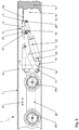
- a device 1 for processing the interior of inaccessible pipes and pipe networks within a pipe 2 to be cleaned is shown schematically.
- This device 1 comprises a nozzle 3 which is movable relative to the inner pipe wall 2a and which is arranged at the front end of the device 1 for generating a forwardly directed, bundled high-pressure nozzle jet 4a of a fluid, for example water.
- the fluid can be present with or without an abrasive.
- the device 1 comprises a media supply 5 for supplying the nozzle 3 with the fluid medium under high pressure.
- the media supply 5 is a hose 5 connected to the nozzle 3.
- the device 1 comprises a housing 6 in which the hose 5 is passed through the housing 6 along a longitudinal axis 7 running through the housing 6, which is shown in FIG Fig. 1 is not shown in detail.
- the nozzle 3 is attached to a front end region 5 a of the hose 5, which is located outside the housing 6, that is to say in front of the housing 6.
- the nozzle 3 is encompassed or at least held by a guide device 8. This enables the nozzle 3 to be guided with an orientation of the The nozzle jet 4a emerging from the nozzle 3 parallel to the pipe wall 2a.
- the distance between the nozzle jet 4a emerging from the nozzle 3 and the pipe wall 2a can be minimized by a feed movement 9 by means of a feed device (not shown), for example by placing the nozzle 3 and / or the guide device 8 on the pipe wall 2a.
- a rotary movement 15 of the nozzle 3 can take place by means of a rotary device with a rotary drive, which is located in the front part 6a of the housing 6, which enables processing / cleaning in different areas of the pipe wall 2a and effectively removes the deposits 14.
- the nozzle 3 or the guide device 8 can be aligned in the axial direction, that is to say in the direction or parallel to the pipe axis 16, by means of a corresponding feed movement 17 of the entire device 1.
- the feed device for the axial feed of the nozzle 3 comprises a plurality of rearwardly directed bores 18, to which the fluid medium can be fed and by means of which a feed movement 17 based on the recoil of the device through the jets 4b of the outflowing from the bores 18 fluid medium can be generated.
- the device comprises at least one camera 19 for detecting the contamination 14 and for observing the alignment and deflection of the nozzle 3.
- a variant of the device 1 can be seen within a tube 2, which has a chassis 20 with wheels 20a, 20b, which is connected to the body 1a of the device 1, which acts as a carrier for the rotating device for the rotational movement 15, the pivoting device and the Delivery device acts. Together with the chassis 20, a feed movement 17 of the entire device 1 can thus take place in the axial direction, that is to say along or parallel to the pipe axis 16.
- the pivot device comprises a further pivot axis 21 for the guide device 8, which is connected to the front part of the arm 12.
- a carrier part 22 for the guide device 8 is mounted on this pivot axis 21, so that the pivot movement 10 of the guide device 8 can take place about this pivot axis 21.
- the arm 12 and the pivot axes 11, 21 can also function as part of a feed device for approaching and / or placing the nozzle and / or the guide device on the pipe wall in order to minimize and / or maintain the distance between the nozzle jet and the pipe wall 2a, which is spaced parallel to one another.
- This length-adjustable support arm 23 is at its rear end via a pivot axis 24 with the body 1 a of the device 1 and at its front end via a further, second pivot axis 25 of the Guide device 8 is connected to the front region of the carrier part 22.
- the pivoting movement of the arm 12 and the movement of the adjustable-length support arm 23 can be coordinated in such a way that during an infeed movement 9 of the carrier part 22 and thus of the guide device 8 with the nozzle 3, the emerging nozzle jet 4a remains aligned parallel to the pipe wall 2a.
- the type of interaction between the arm 12 and the length-adjustable support arm 23 decides whether an infeed movement 9 with the nozzle jet 4a aligned parallel to the pipe wall 2a or a pivoting movement 10 of the guide device 8 and thus a deflection of the nozzle jet 4a from parallelism to the pipe wall 2a in the direction of the center of the pipe 13 in order to be able to remove dirt / deposits 14 also in the center of the pipe 13.
- This device also comprises at least one (in Fig. 2 camera (not shown) for detecting the contamination 14 and observing the alignment and deflection of the at least one nozzle 3.
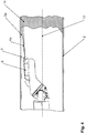
- the Fig. 3 shows schematically a nozzle 3 guided within a pipe 2 by means of a guide device 8 with an exiting nozzle jet 4a which is inclined from the parallelism to the pipe wall 2a in the direction of the pipe center 13.
- the Fig. 4 shows schematically a nozzle 3 guided within a pipe 2 by means of a guide device 8 with an exiting nozzle jet 4a, which is inclined from the parallelism to the pipe wall 2a - against the pipe center 13 - in the direction of the pipe wall 2a, i.e. with an inclination in the direction of the more closely spaced pipe wall 2a exits.
- the nozzle jet 4a is inclined in the direction of the pipe wall 2a only to such an extent that the pipe wall 2a is not damaged. In any case, the aim is to prevent the nozzle jet 4a from hitting the pipe wall 2a at too close a distance.
- the nozzle jet 4a With a greater distance of the nozzle jet 4a to impinge on the Pipe wall 2a, the nozzle jet is widened more and at a smaller angle the point of impact takes up a larger area. This means that the force emanating from the nozzle jet per area of the pipe wall is lower. For this reason, if the angle is limited, the likelihood of damage to the pipe wall is significantly lower.
- the infeed device and / or the pivoting device of the device 1 preferably has / have one or more inclination limiting devices which ensure that the nozzle jet 4a guided parallel to the pipe wall 2a can only be inclined towards the pipe wall 2a to such an extent that the pipe wall 2a is not damaged.
- the maximum value for the adjustable angle depends on the pipe material used and the high pressure used. Due to an adjustable inclination between the pipe wall 2a and the nozzle jet 4a, efficient removal of the deposits 14 is also ensured in the edge regions of the pipe 2.
Landscapes
- Engineering & Computer Science (AREA)
- Mechanical Engineering (AREA)
- Cleaning In General (AREA)
Claims (11)
- Dispositif (1) pour le traitement de l'intérieur de tuyaux et réseaux de tuyauterie inaccessibles au moyen de jets haute pression d'un fluide avec ou sans moyen abrasif, comprenant• au moins une buse (3) qui est disposée à l'extrémité avant du dispositif (1) pour la génération d'au moins un jet de buse concentré (4a) du fluide, orienté vers l'avant,• une amenée de milieu pour l'alimentation de l'au moins une buse (3) avec le milieu fluide se trouvant sous haute pression,• une installation de guidage (8) pour le guidage de l'au moins une buse (3) avec une orientation de l'au moins un jet de buse (4a) sortant de la buse (3) parallèlement à la paroi de tuyau (2a),• une installation d'approche pour un rapprochement ou un appui de l'au moins une buse (3) ou de l'installation de guidage (8) de/sur la paroi de tuyau en vue de minimiser ou maintenir l'écart de l'au moins un jet de buse (4a) par rapport à la paroi de tuyau (2a) écartée parallèlement au jet de buse (4a) et/ou
une installation de pivotement pour une déviation de l'au moins un jet de buse (4a) du parallélisme à la paroi de tuyau (2a) en direction du milieu de tuyau (13),• une installation de rotation pour un mouvement de rotation de l'au moins une buse (3) autour de l'axe de tuyau (16) ou d'un axe parallèle à l'axe de tuyau (16) le long de la paroi de tuyau (2a) dans le cas d'un guidage en principe parallèle du jet de buse (4a) par rapport à la paroi de tuyau (2a) par l'installation de guidage (8),• une installation d'avance pour un mouvement d'avance axial (17) le long de ou parallèlement à l'axe de tuyau (16), et• au moins une caméra (19) pour l'observation de l'orientation et la déviation de l'au moins une buse (3). - Dispositif selon la revendication 1, caractérisé en ce que l'installation de guidage (8) convient en outre au guidage de l'au moins une buse (3) avec une orientation parallèle de l'au moins un jet de buse (4a) sortant de la buse (3) pour un guidage de l'au moins une buse (3) avec une orientation de l'au moins un jet de buse (4a), lors de laquelle l'au moins un jet de buse (4a) est légèrement incliné au sein du tuyau (2) vers la paroi de tuyau (2a) de laquelle l'au moins une buse (3) est rapprochée ou contre laquelle elle repose, ou légèrement incliné à l'écart de cette paroi de tuyau (2a) de telle sorte que la paroi de tuyau (2a) n'est pas endommagée.
- Dispositif selon la revendication 1 ou 2, caractérisé en ce que l'installation de guidage (8) est réalisée en tant que patin de guidage et/ou en tant que chariot de guidage.
- Dispositif selon une des revendications 1 à 3, caractérisé en ce que l'installation de guidage (8) comprend une installation de balayage avec réglage.
- Dispositif selon une des revendications 1 à 4, caractérisé en ce que l'installation de guidage (8) présente un capteur au moyen duquel l'écart de l'au moins une buse (3) et/ou de l'au moins un jet de buse (4a) sortant de la paroi de tuyau (2a) écartée parallèlement peut être déterminé et l'écart par rapport à la paroi de tuyau peut être recalibré ou régulé par le biais de l'installation d'approche et/ou l'installation de pivotement.
- Dispositif selon une des revendications 1 à 5, caractérisé en ce que l'installation d'approche et/ou l'installation de pivotement comprend une ou plusieurs installations de limitation d'inclinaison qui garantissent que l'au moins un jet de buse (4a) guidé parallèlement à la paroi de tuyau (2a) ne peut être incliné en direction de la paroi de tuyau (2a) que dans la mesure où la paroi de tuyau (2a) n'est pas endommagée.
- Dispositif selon une des revendications 1 à 6, caractérisé en ce que l'installation d'avance comprend un(e) ou plusieurs alésages (18) ou buses orienté(e)s vers l'arrière auxquel(le)s le milieu fluide peut être amené et au moyen desquel(le)s un mouvement d'avance (17) du dispositif, reposant sur le recul, peut être généré par des jets (4b) du milieu fluide s'écoulant des alésages (18) ou buses.
- Dispositif selon une des revendications 1 à 6, caractérisé en ce que celui-ci comprend un mécanisme de roulement (20) avec des roues (20a, 20b) pour le mouvement d'avance axial (17).
- Dispositif selon une des revendications 1 à 8, caractérisé en ce qu'aucune installation d'approche n'est prévue et l'écart de l'au moins une buse (3) et/ou de l'installation de guidage (8) par rapport à la paroi de tuyau (2a) est réglé de manière fixe.
- Dispositif selon une des revendications 1 à 8, caractérisé en ce que l'installation d'approche convient à déplacer l'au moins une buse (3) et/ou l'installation de guidage (8) en direction du milieu de tuyau (13) pour pouvoir également décaper les salissures/dépôts (14) dans le milieu de tuyau (13), dans lequel l'au moins un jet de buse (4a) conserve le parallélisme à la paroi de tuyau (2a).
- Dispositif selon une des revendications 1 à 10, caractérisé en ce que l'installation de pivotement est réalisée de telle sorte qu'elle convient en outre à la déviation de l'au moins un jet de buse (4a) également pour un rapprochement et/ou un appui de l'au moins une buse (3) et/ou de l'installation de guidage (8) de/sur la paroi de tuyau en maintenant le parallélisme de l'au moins un jet de buse (4a) par rapport à la paroi de tuyau écartée (2a).
Priority Applications (1)
| Application Number | Priority Date | Filing Date | Title |
|---|---|---|---|
| EP16168758.7A EP3243576B1 (fr) | 2016-05-09 | 2016-05-09 | Dispositif de traitement l'interieur de tuyaux non accessibles et de tuyauterie a l'aide de projection de jet haute pression d'un fluide |
Applications Claiming Priority (1)
| Application Number | Priority Date | Filing Date | Title |
|---|---|---|---|
| EP16168758.7A EP3243576B1 (fr) | 2016-05-09 | 2016-05-09 | Dispositif de traitement l'interieur de tuyaux non accessibles et de tuyauterie a l'aide de projection de jet haute pression d'un fluide |
Publications (2)
| Publication Number | Publication Date |
|---|---|
| EP3243576A1 EP3243576A1 (fr) | 2017-11-15 |
| EP3243576B1 true EP3243576B1 (fr) | 2021-09-01 |
Family
ID=56097991
Family Applications (1)
| Application Number | Title | Priority Date | Filing Date |
|---|---|---|---|
| EP16168758.7A Active EP3243576B1 (fr) | 2016-05-09 | 2016-05-09 | Dispositif de traitement l'interieur de tuyaux non accessibles et de tuyauterie a l'aide de projection de jet haute pression d'un fluide |
Country Status (1)
| Country | Link |
|---|---|
| EP (1) | EP3243576B1 (fr) |
Families Citing this family (6)
| Publication number | Priority date | Publication date | Assignee | Title |
|---|---|---|---|---|
| CN107999474B (zh) * | 2017-12-15 | 2018-10-12 | 东海县正东石英制品有限公司 | 一种管件内壁清洁装置 |
| CN108043831B (zh) * | 2017-12-15 | 2018-11-02 | 长春近江汽车零部件有限公司 | 一种新型管件内壁清洁装置 |
| CN109304336A (zh) * | 2018-11-09 | 2019-02-05 | 中国建筑第八工程局有限公司 | 混凝土输送泵管快速疏通和清理装置 |
| CN110280550B (zh) * | 2019-07-29 | 2024-08-13 | 河北工业职业技术学院 | 管道内壁清扫机器人 |
| CN112845306B (zh) * | 2021-01-04 | 2022-06-17 | 中铁第五勘察设计院集团有限公司 | 钻杆清洗装置 |
| CN115112347A (zh) * | 2021-03-19 | 2022-09-27 | 中国石油化工股份有限公司 | 一种淹没水射流冲砂性能实验装置及方法 |
Family Cites Families (5)
| Publication number | Priority date | Publication date | Assignee | Title |
|---|---|---|---|---|
| JPH08141534A (ja) | 1994-11-17 | 1996-06-04 | Toshiba Corp | 管内清掃ロボット |
| DE19626590C2 (de) | 1996-07-02 | 2000-12-07 | Aquaplus Brunnensanierung H Mu | Vorrichtung zum Reinigen der Innenflächen von Rohren, wie Brunnenrohren in Brunnenschächten |
| JP4420935B2 (ja) | 2007-05-14 | 2010-02-24 | 株式会社山崎塗装店 | ライニング配管内の洗浄方法 |
| DE202014000026U1 (de) | 2014-01-07 | 2014-03-10 | Mauerspecht GmbH | Vorrichtung zum Bearbeiten von Kanalwandungen mittels Hochdruck-Flüssigkeitsstrahlen |
| DE202014105354U1 (de) * | 2014-11-07 | 2014-11-19 | Hydrotec Germany Gmbh | Vorrichtung zur Reinigung von Rohren |
-
2016
- 2016-05-09 EP EP16168758.7A patent/EP3243576B1/fr active Active
Also Published As
| Publication number | Publication date |
|---|---|
| EP3243576A1 (fr) | 2017-11-15 |
Similar Documents
| Publication | Publication Date | Title |
|---|---|---|
| EP3243576B1 (fr) | Dispositif de traitement l'interieur de tuyaux non accessibles et de tuyauterie a l'aide de projection de jet haute pression d'un fluide | |
| WO2010142283A1 (fr) | Système modulaire pour un soudage par métal d'apport sur des surfaces internes de pièces par un faisceau laser | |
| EP2695728B1 (fr) | Dispositif destinés au nettoyage de moules de vulcanisation | |
| EP3017885A1 (fr) | Dispositif de nettoyage de tuyaux | |
| EP0172244B1 (fr) | Installation de nettoyage des surfaces d'echange thermique des masses d'accumulation d'echangeurs thermiques a regeneration circulante | |
| DE102010006608A1 (de) | Vorrichtung zum Hochdruck-Wasserstrahlschneiden in geschlossenen Kanälen | |
| EP2891526B1 (fr) | Dispositif et procédé de traitement de parois de canal au moyen de rayonnements liquides haute pression | |
| EP1044859B1 (fr) | Dispositif de séchage pour sécher les véhicules dans une station de lavage de voiture | |
| DE2107861B2 (de) | Rußblaser | |
| EP3017872A1 (fr) | Dispositif de jet d'eau haute pression, dispositif de nettoyage de canal et procédé de jet d'eau haute pression | |
| DE10215446B4 (de) | Kombinierter Laserkopf für verschiedene Laserbearbeitungen | |
| DE102011112003A1 (de) | Vorrichtung zur Reinigung und/oder Überprüfung von Freilandsolaranlagen | |
| EP2985116B1 (fr) | Dispositif de nettoyage et procédé de nettoyage de rouleaux de transport dans un four à refroidisseur à rouleaux d'une installation de production de verre flotté | |
| DE102015110912B4 (de) | Reinigungssystem | |
| EP3941678B1 (fr) | Dispositif pour introduire un agent de séparation dans une pièce ouvrée creuse | |
| EP4115133B1 (fr) | Appareil pour le nettoyage partiellement automatisé d'échangeurs de chaleur à faisceau de tubes, ensemble de nettoyage d'échangeur de chaleur à faisceau de tubes, et procédé de sablage destiné à nettoyer une surface de tube interne d'un tube d'un échangeur de chaleur à faisceau de tubes | |
| DE102017117547A1 (de) | Vorrichtung zum Reinigen von Werkstücken, insbesondere bündelweise verbundenen Rohren | |
| DE102006023709B3 (de) | Strahllanze | |
| DE19911382B4 (de) | Werkzeugführungssystem | |
| DE202004020627U1 (de) | Vorrichtung zur Inspektion von Schächten und Rohren | |
| EP4524542B1 (fr) | Système de positionnement pour systèmes d'inspection et/ou de maintenance de canal | |
| DE10144962B4 (de) | Reinigungswerkzeug für Kanäle | |
| DE102008045465B4 (de) | An einem Bearbeitungsportal verschiebbare Werkzeugstation mit einer Granulatstrahleinheit und einem Markierwerkzeug | |
| DE69927504T2 (de) | Spritzreiniger für die innere oberfläche einer rohrleitung | |
| DE202023105294U1 (de) | Positionierungssystem für Kanalinspektions- und/oder Wartungssysteme |
Legal Events
| Date | Code | Title | Description |
|---|---|---|---|
| PUAI | Public reference made under article 153(3) epc to a published international application that has entered the european phase |
Free format text: ORIGINAL CODE: 0009012 |
|
| STAA | Information on the status of an ep patent application or granted ep patent |
Free format text: STATUS: THE APPLICATION HAS BEEN PUBLISHED |
|
| AK | Designated contracting states |
Kind code of ref document: A1 Designated state(s): AL AT BE BG CH CY CZ DE DK EE ES FI FR GB GR HR HU IE IS IT LI LT LU LV MC MK MT NL NO PL PT RO RS SE SI SK SM TR |
|
| AX | Request for extension of the european patent |
Extension state: BA ME |
|
| RAP1 | Party data changed (applicant data changed or rights of an application transferred) |
Owner name: IMS ROBOTICS GMBH |
|
| STAA | Information on the status of an ep patent application or granted ep patent |
Free format text: STATUS: REQUEST FOR EXAMINATION WAS MADE |
|
| 17P | Request for examination filed |
Effective date: 20180515 |
|
| RBV | Designated contracting states (corrected) |
Designated state(s): AL AT BE BG CH CY CZ DE DK EE ES FI FR GB GR HR HU IE IS IT LI LT LU LV MC MK MT NL NO PL PT RO RS SE SI SK SM TR |
|
| GRAP | Despatch of communication of intention to grant a patent |
Free format text: ORIGINAL CODE: EPIDOSNIGR1 |
|
| STAA | Information on the status of an ep patent application or granted ep patent |
Free format text: STATUS: GRANT OF PATENT IS INTENDED |
|
| INTG | Intention to grant announced |
Effective date: 20210504 |
|
| GRAS | Grant fee paid |
Free format text: ORIGINAL CODE: EPIDOSNIGR3 |
|
| GRAA | (expected) grant |
Free format text: ORIGINAL CODE: 0009210 |
|
| STAA | Information on the status of an ep patent application or granted ep patent |
Free format text: STATUS: THE PATENT HAS BEEN GRANTED |
|
| AK | Designated contracting states |
Kind code of ref document: B1 Designated state(s): AL AT BE BG CH CY CZ DE DK EE ES FI FR GB GR HR HU IE IS IT LI LT LU LV MC MK MT NL NO PL PT RO RS SE SI SK SM TR |
|
| REG | Reference to a national code |
Ref country code: GB Ref legal event code: FG4D Free format text: NOT ENGLISH |
|
| REG | Reference to a national code |
Ref country code: CH Ref legal event code: EP Ref country code: AT Ref legal event code: REF Ref document number: 1425669 Country of ref document: AT Kind code of ref document: T Effective date: 20210915 |
|
| REG | Reference to a national code |
Ref country code: DE Ref legal event code: R096 Ref document number: 502016013735 Country of ref document: DE |
|
| REG | Reference to a national code |
Ref country code: IE Ref legal event code: FG4D Free format text: LANGUAGE OF EP DOCUMENT: GERMAN |
|
| REG | Reference to a national code |
Ref country code: LT Ref legal event code: MG9D |
|
| REG | Reference to a national code |
Ref country code: NL Ref legal event code: MP Effective date: 20210901 |
|
| PG25 | Lapsed in a contracting state [announced via postgrant information from national office to epo] |
Ref country code: SE Free format text: LAPSE BECAUSE OF FAILURE TO SUBMIT A TRANSLATION OF THE DESCRIPTION OR TO PAY THE FEE WITHIN THE PRESCRIBED TIME-LIMIT Effective date: 20210901 Ref country code: RS Free format text: LAPSE BECAUSE OF FAILURE TO SUBMIT A TRANSLATION OF THE DESCRIPTION OR TO PAY THE FEE WITHIN THE PRESCRIBED TIME-LIMIT Effective date: 20210901 Ref country code: HR Free format text: LAPSE BECAUSE OF FAILURE TO SUBMIT A TRANSLATION OF THE DESCRIPTION OR TO PAY THE FEE WITHIN THE PRESCRIBED TIME-LIMIT Effective date: 20210901 Ref country code: ES Free format text: LAPSE BECAUSE OF FAILURE TO SUBMIT A TRANSLATION OF THE DESCRIPTION OR TO PAY THE FEE WITHIN THE PRESCRIBED TIME-LIMIT Effective date: 20210901 Ref country code: FI Free format text: LAPSE BECAUSE OF FAILURE TO SUBMIT A TRANSLATION OF THE DESCRIPTION OR TO PAY THE FEE WITHIN THE PRESCRIBED TIME-LIMIT Effective date: 20210901 Ref country code: NO Free format text: LAPSE BECAUSE OF FAILURE TO SUBMIT A TRANSLATION OF THE DESCRIPTION OR TO PAY THE FEE WITHIN THE PRESCRIBED TIME-LIMIT Effective date: 20211201 Ref country code: LT Free format text: LAPSE BECAUSE OF FAILURE TO SUBMIT A TRANSLATION OF THE DESCRIPTION OR TO PAY THE FEE WITHIN THE PRESCRIBED TIME-LIMIT Effective date: 20210901 Ref country code: BG Free format text: LAPSE BECAUSE OF FAILURE TO SUBMIT A TRANSLATION OF THE DESCRIPTION OR TO PAY THE FEE WITHIN THE PRESCRIBED TIME-LIMIT Effective date: 20211201 |
|
| PG25 | Lapsed in a contracting state [announced via postgrant information from national office to epo] |
Ref country code: PL Free format text: LAPSE BECAUSE OF FAILURE TO SUBMIT A TRANSLATION OF THE DESCRIPTION OR TO PAY THE FEE WITHIN THE PRESCRIBED TIME-LIMIT Effective date: 20210901 Ref country code: LV Free format text: LAPSE BECAUSE OF FAILURE TO SUBMIT A TRANSLATION OF THE DESCRIPTION OR TO PAY THE FEE WITHIN THE PRESCRIBED TIME-LIMIT Effective date: 20210901 Ref country code: GR Free format text: LAPSE BECAUSE OF FAILURE TO SUBMIT A TRANSLATION OF THE DESCRIPTION OR TO PAY THE FEE WITHIN THE PRESCRIBED TIME-LIMIT Effective date: 20211202 |
|
| PG25 | Lapsed in a contracting state [announced via postgrant information from national office to epo] |
Ref country code: IS Free format text: LAPSE BECAUSE OF FAILURE TO SUBMIT A TRANSLATION OF THE DESCRIPTION OR TO PAY THE FEE WITHIN THE PRESCRIBED TIME-LIMIT Effective date: 20220101 Ref country code: SM Free format text: LAPSE BECAUSE OF FAILURE TO SUBMIT A TRANSLATION OF THE DESCRIPTION OR TO PAY THE FEE WITHIN THE PRESCRIBED TIME-LIMIT Effective date: 20210901 Ref country code: SK Free format text: LAPSE BECAUSE OF FAILURE TO SUBMIT A TRANSLATION OF THE DESCRIPTION OR TO PAY THE FEE WITHIN THE PRESCRIBED TIME-LIMIT Effective date: 20210901 Ref country code: RO Free format text: LAPSE BECAUSE OF FAILURE TO SUBMIT A TRANSLATION OF THE DESCRIPTION OR TO PAY THE FEE WITHIN THE PRESCRIBED TIME-LIMIT Effective date: 20210901 Ref country code: PT Free format text: LAPSE BECAUSE OF FAILURE TO SUBMIT A TRANSLATION OF THE DESCRIPTION OR TO PAY THE FEE WITHIN THE PRESCRIBED TIME-LIMIT Effective date: 20220103 Ref country code: NL Free format text: LAPSE BECAUSE OF FAILURE TO SUBMIT A TRANSLATION OF THE DESCRIPTION OR TO PAY THE FEE WITHIN THE PRESCRIBED TIME-LIMIT Effective date: 20210901 Ref country code: EE Free format text: LAPSE BECAUSE OF FAILURE TO SUBMIT A TRANSLATION OF THE DESCRIPTION OR TO PAY THE FEE WITHIN THE PRESCRIBED TIME-LIMIT Effective date: 20210901 Ref country code: CZ Free format text: LAPSE BECAUSE OF FAILURE TO SUBMIT A TRANSLATION OF THE DESCRIPTION OR TO PAY THE FEE WITHIN THE PRESCRIBED TIME-LIMIT Effective date: 20210901 Ref country code: AL Free format text: LAPSE BECAUSE OF FAILURE TO SUBMIT A TRANSLATION OF THE DESCRIPTION OR TO PAY THE FEE WITHIN THE PRESCRIBED TIME-LIMIT Effective date: 20210901 |
|
| REG | Reference to a national code |
Ref country code: DE Ref legal event code: R097 Ref document number: 502016013735 Country of ref document: DE |
|
| PLBE | No opposition filed within time limit |
Free format text: ORIGINAL CODE: 0009261 |
|
| STAA | Information on the status of an ep patent application or granted ep patent |
Free format text: STATUS: NO OPPOSITION FILED WITHIN TIME LIMIT |
|
| PG25 | Lapsed in a contracting state [announced via postgrant information from national office to epo] |
Ref country code: IT Free format text: LAPSE BECAUSE OF FAILURE TO SUBMIT A TRANSLATION OF THE DESCRIPTION OR TO PAY THE FEE WITHIN THE PRESCRIBED TIME-LIMIT Effective date: 20210901 Ref country code: DK Free format text: LAPSE BECAUSE OF FAILURE TO SUBMIT A TRANSLATION OF THE DESCRIPTION OR TO PAY THE FEE WITHIN THE PRESCRIBED TIME-LIMIT Effective date: 20210901 |
|
| 26N | No opposition filed |
Effective date: 20220602 |
|
| PG25 | Lapsed in a contracting state [announced via postgrant information from national office to epo] |
Ref country code: SI Free format text: LAPSE BECAUSE OF FAILURE TO SUBMIT A TRANSLATION OF THE DESCRIPTION OR TO PAY THE FEE WITHIN THE PRESCRIBED TIME-LIMIT Effective date: 20210901 |
|
| REG | Reference to a national code |
Ref country code: BE Ref legal event code: MM Effective date: 20220531 |
|
| GBPC | Gb: european patent ceased through non-payment of renewal fee |
Effective date: 20220509 |
|
| PG25 | Lapsed in a contracting state [announced via postgrant information from national office to epo] |
Ref country code: MC Free format text: LAPSE BECAUSE OF FAILURE TO SUBMIT A TRANSLATION OF THE DESCRIPTION OR TO PAY THE FEE WITHIN THE PRESCRIBED TIME-LIMIT Effective date: 20210901 Ref country code: LU Free format text: LAPSE BECAUSE OF NON-PAYMENT OF DUE FEES Effective date: 20220509 |
|
| PG25 | Lapsed in a contracting state [announced via postgrant information from national office to epo] |
Ref country code: IE Free format text: LAPSE BECAUSE OF NON-PAYMENT OF DUE FEES Effective date: 20220509 Ref country code: FR Free format text: LAPSE BECAUSE OF NON-PAYMENT OF DUE FEES Effective date: 20220531 |
|
| PG25 | Lapsed in a contracting state [announced via postgrant information from national office to epo] |
Ref country code: GB Free format text: LAPSE BECAUSE OF NON-PAYMENT OF DUE FEES Effective date: 20220509 Ref country code: BE Free format text: LAPSE BECAUSE OF NON-PAYMENT OF DUE FEES Effective date: 20220531 |
|
| REG | Reference to a national code |
Ref country code: AT Ref legal event code: MM01 Ref document number: 1425669 Country of ref document: AT Kind code of ref document: T Effective date: 20220509 |
|
| P01 | Opt-out of the competence of the unified patent court (upc) registered |
Effective date: 20230613 |
|
| PG25 | Lapsed in a contracting state [announced via postgrant information from national office to epo] |
Ref country code: AT Free format text: LAPSE BECAUSE OF NON-PAYMENT OF DUE FEES Effective date: 20220509 |
|
| PG25 | Lapsed in a contracting state [announced via postgrant information from national office to epo] |
Ref country code: HU Free format text: LAPSE BECAUSE OF FAILURE TO SUBMIT A TRANSLATION OF THE DESCRIPTION OR TO PAY THE FEE WITHIN THE PRESCRIBED TIME-LIMIT; INVALID AB INITIO Effective date: 20160509 |
|
| PG25 | Lapsed in a contracting state [announced via postgrant information from national office to epo] |
Ref country code: MK Free format text: LAPSE BECAUSE OF FAILURE TO SUBMIT A TRANSLATION OF THE DESCRIPTION OR TO PAY THE FEE WITHIN THE PRESCRIBED TIME-LIMIT Effective date: 20210901 Ref country code: CY Free format text: LAPSE BECAUSE OF FAILURE TO SUBMIT A TRANSLATION OF THE DESCRIPTION OR TO PAY THE FEE WITHIN THE PRESCRIBED TIME-LIMIT Effective date: 20210901 |
|
| PG25 | Lapsed in a contracting state [announced via postgrant information from national office to epo] |
Ref country code: TR Free format text: LAPSE BECAUSE OF FAILURE TO SUBMIT A TRANSLATION OF THE DESCRIPTION OR TO PAY THE FEE WITHIN THE PRESCRIBED TIME-LIMIT Effective date: 20210901 |
|
| PG25 | Lapsed in a contracting state [announced via postgrant information from national office to epo] |
Ref country code: MT Free format text: LAPSE BECAUSE OF FAILURE TO SUBMIT A TRANSLATION OF THE DESCRIPTION OR TO PAY THE FEE WITHIN THE PRESCRIBED TIME-LIMIT Effective date: 20210901 |
|
| PGFP | Annual fee paid to national office [announced via postgrant information from national office to epo] |
Ref country code: DE Payment date: 20250519 Year of fee payment: 10 |
|
| PGFP | Annual fee paid to national office [announced via postgrant information from national office to epo] |
Ref country code: CH Payment date: 20250601 Year of fee payment: 10 |