EP3243600A2 - Usinage de surface portante - Google Patents
Usinage de surface portante Download PDFInfo
- Publication number
- EP3243600A2 EP3243600A2 EP17170230.1A EP17170230A EP3243600A2 EP 3243600 A2 EP3243600 A2 EP 3243600A2 EP 17170230 A EP17170230 A EP 17170230A EP 3243600 A2 EP3243600 A2 EP 3243600A2
- Authority
- EP
- European Patent Office
- Prior art keywords
- component
- medium
- fixture
- toolset
- orientation
- Prior art date
- Legal status (The legal status is an assumption and is not a legal conclusion. Google has not performed a legal analysis and makes no representation as to the accuracy of the status listed.)
- Granted
Links
Images

Classifications
-
- B—PERFORMING OPERATIONS; TRANSPORTING
- B23—MACHINE TOOLS; METAL-WORKING NOT OTHERWISE PROVIDED FOR
- B23Q—DETAILS, COMPONENTS, OR ACCESSORIES FOR MACHINE TOOLS, e.g. ARRANGEMENTS FOR COPYING OR CONTROLLING; MACHINE TOOLS IN GENERAL CHARACTERISED BY THE CONSTRUCTION OF PARTICULAR DETAILS OR COMPONENTS; COMBINATIONS OR ASSOCIATIONS OF METAL-WORKING MACHINES, NOT DIRECTED TO A PARTICULAR RESULT
- B23Q3/00—Devices holding, supporting, or positioning work or tools, of a kind normally removable from the machine
- B23Q3/02—Devices holding, supporting, or positioning work or tools, of a kind normally removable from the machine for mounting on a work-table, tool-slide, or analogous part
- B23Q3/06—Work-clamping means
- B23Q3/08—Work-clamping means other than mechanically-actuated
- B23Q3/086—Work-clamping means other than mechanically-actuated using a solidifying liquid, e.g. with freezing, setting or hardening means
-
- B—PERFORMING OPERATIONS; TRANSPORTING
- B23—MACHINE TOOLS; METAL-WORKING NOT OTHERWISE PROVIDED FOR
- B23Q—DETAILS, COMPONENTS, OR ACCESSORIES FOR MACHINE TOOLS, e.g. ARRANGEMENTS FOR COPYING OR CONTROLLING; MACHINE TOOLS IN GENERAL CHARACTERISED BY THE CONSTRUCTION OF PARTICULAR DETAILS OR COMPONENTS; COMBINATIONS OR ASSOCIATIONS OF METAL-WORKING MACHINES, NOT DIRECTED TO A PARTICULAR RESULT
- B23Q11/00—Accessories fitted to machine tools for keeping tools or parts of the machine in good working condition or for cooling work; Safety devices specially combined with or arranged in, or specially adapted for use in connection with, machine tools
- B23Q11/12—Arrangements for cooling or lubricating parts of the machine
- B23Q11/126—Arrangements for cooling or lubricating parts of the machine for cooling only
-
- B—PERFORMING OPERATIONS; TRANSPORTING
- B23—MACHINE TOOLS; METAL-WORKING NOT OTHERWISE PROVIDED FOR
- B23Q—DETAILS, COMPONENTS, OR ACCESSORIES FOR MACHINE TOOLS, e.g. ARRANGEMENTS FOR COPYING OR CONTROLLING; MACHINE TOOLS IN GENERAL CHARACTERISED BY THE CONSTRUCTION OF PARTICULAR DETAILS OR COMPONENTS; COMBINATIONS OR ASSOCIATIONS OF METAL-WORKING MACHINES, NOT DIRECTED TO A PARTICULAR RESULT
- B23Q17/00—Arrangements for observing, indicating or measuring on machine tools
- B23Q17/22—Arrangements for observing, indicating or measuring on machine tools for indicating or measuring existing or desired position of tool or work
- B23Q17/2233—Arrangements for observing, indicating or measuring on machine tools for indicating or measuring existing or desired position of tool or work for adjusting the tool relative to the workpiece
-
- B—PERFORMING OPERATIONS; TRANSPORTING
- B23—MACHINE TOOLS; METAL-WORKING NOT OTHERWISE PROVIDED FOR
- B23Q—DETAILS, COMPONENTS, OR ACCESSORIES FOR MACHINE TOOLS, e.g. ARRANGEMENTS FOR COPYING OR CONTROLLING; MACHINE TOOLS IN GENERAL CHARACTERISED BY THE CONSTRUCTION OF PARTICULAR DETAILS OR COMPONENTS; COMBINATIONS OR ASSOCIATIONS OF METAL-WORKING MACHINES, NOT DIRECTED TO A PARTICULAR RESULT
- B23Q3/00—Devices holding, supporting, or positioning work or tools, of a kind normally removable from the machine
- B23Q3/02—Devices holding, supporting, or positioning work or tools, of a kind normally removable from the machine for mounting on a work-table, tool-slide, or analogous part
- B23Q3/06—Work-clamping means
- B23Q3/062—Work-clamping means adapted for holding workpieces having a special form or being made from a special material
- B23Q3/063—Work-clamping means adapted for holding workpieces having a special form or being made from a special material for holding turbine blades
-
- F—MECHANICAL ENGINEERING; LIGHTING; HEATING; WEAPONS; BLASTING
- F01—MACHINES OR ENGINES IN GENERAL; ENGINE PLANTS IN GENERAL; STEAM ENGINES
- F01D—NON-POSITIVE DISPLACEMENT MACHINES OR ENGINES, e.g. STEAM TURBINES
- F01D5/00—Blades; Blade-carrying members; Heating, heat-insulating, cooling or antivibration means on the blades or the members
- F01D5/12—Blades
- F01D5/14—Form or construction
- F01D5/147—Construction, i.e. structural features, e.g. of weight-saving hollow blades
-
- F—MECHANICAL ENGINEERING; LIGHTING; HEATING; WEAPONS; BLASTING
- F01—MACHINES OR ENGINES IN GENERAL; ENGINE PLANTS IN GENERAL; STEAM ENGINES
- F01D—NON-POSITIVE DISPLACEMENT MACHINES OR ENGINES, e.g. STEAM TURBINES
- F01D5/00—Blades; Blade-carrying members; Heating, heat-insulating, cooling or antivibration means on the blades or the members
- F01D5/30—Fixing blades to rotors; Blade roots ; Blade spacers
-
- F—MECHANICAL ENGINEERING; LIGHTING; HEATING; WEAPONS; BLASTING
- F04—POSITIVE - DISPLACEMENT MACHINES FOR LIQUIDS; PUMPS FOR LIQUIDS OR ELASTIC FLUIDS
- F04D—NON-POSITIVE-DISPLACEMENT PUMPS
- F04D29/00—Details, component parts, or accessories
- F04D29/26—Rotors specially for elastic fluids
- F04D29/32—Rotors specially for elastic fluids for axial flow pumps
- F04D29/321—Rotors specially for elastic fluids for axial flow pumps for axial flow compressors
- F04D29/322—Blade mountings
-
- F—MECHANICAL ENGINEERING; LIGHTING; HEATING; WEAPONS; BLASTING
- F04—POSITIVE - DISPLACEMENT MACHINES FOR LIQUIDS; PUMPS FOR LIQUIDS OR ELASTIC FLUIDS
- F04D—NON-POSITIVE-DISPLACEMENT PUMPS
- F04D29/00—Details, component parts, or accessories
- F04D29/26—Rotors specially for elastic fluids
- F04D29/32—Rotors specially for elastic fluids for axial flow pumps
- F04D29/321—Rotors specially for elastic fluids for axial flow pumps for axial flow compressors
- F04D29/324—Blades
-
- F—MECHANICAL ENGINEERING; LIGHTING; HEATING; WEAPONS; BLASTING
- F04—POSITIVE - DISPLACEMENT MACHINES FOR LIQUIDS; PUMPS FOR LIQUIDS OR ELASTIC FLUIDS
- F04D—NON-POSITIVE-DISPLACEMENT PUMPS
- F04D29/00—Details, component parts, or accessories
- F04D29/26—Rotors specially for elastic fluids
- F04D29/32—Rotors specially for elastic fluids for axial flow pumps
- F04D29/34—Blade mountings
-
- F—MECHANICAL ENGINEERING; LIGHTING; HEATING; WEAPONS; BLASTING
- F04—POSITIVE - DISPLACEMENT MACHINES FOR LIQUIDS; PUMPS FOR LIQUIDS OR ELASTIC FLUIDS
- F04D—NON-POSITIVE-DISPLACEMENT PUMPS
- F04D29/00—Details, component parts, or accessories
- F04D29/26—Rotors specially for elastic fluids
- F04D29/32—Rotors specially for elastic fluids for axial flow pumps
- F04D29/38—Blades
-
- F—MECHANICAL ENGINEERING; LIGHTING; HEATING; WEAPONS; BLASTING
- F05—INDEXING SCHEMES RELATING TO ENGINES OR PUMPS IN VARIOUS SUBCLASSES OF CLASSES F01-F04
- F05D—INDEXING SCHEME FOR ASPECTS RELATING TO NON-POSITIVE-DISPLACEMENT MACHINES OR ENGINES, GAS-TURBINES OR JET-PROPULSION PLANTS
- F05D2220/00—Application
- F05D2220/30—Application in turbines
- F05D2220/32—Application in turbines in gas turbines
-
- F—MECHANICAL ENGINEERING; LIGHTING; HEATING; WEAPONS; BLASTING
- F05—INDEXING SCHEMES RELATING TO ENGINES OR PUMPS IN VARIOUS SUBCLASSES OF CLASSES F01-F04
- F05D—INDEXING SCHEME FOR ASPECTS RELATING TO NON-POSITIVE-DISPLACEMENT MACHINES OR ENGINES, GAS-TURBINES OR JET-PROPULSION PLANTS
- F05D2230/00—Manufacture
- F05D2230/10—Manufacture by removing material
-
- F—MECHANICAL ENGINEERING; LIGHTING; HEATING; WEAPONS; BLASTING
- F05—INDEXING SCHEMES RELATING TO ENGINES OR PUMPS IN VARIOUS SUBCLASSES OF CLASSES F01-F04
- F05D—INDEXING SCHEME FOR ASPECTS RELATING TO NON-POSITIVE-DISPLACEMENT MACHINES OR ENGINES, GAS-TURBINES OR JET-PROPULSION PLANTS
- F05D2230/00—Manufacture
- F05D2230/30—Manufacture with deposition of material
Definitions
- one or more components of the engine may be machined.
- a blade of the engine may be placed in a fixture and a portion of the blade (e.g., a root, an attachment, a platform, etc.) may be machined.
- the fixture is typically made of a metal alloy that has a melting-point temperature that is less than a second melting-point temperature associated with the component (e.g., the blade).
- the component is inserted in the fixture and then the metal alloy is allowed to cool to a temperature that is less than the melting-point temperature of the metal alloy such that the metal alloy solidifies and holds the component in place.
- the technician/operator performs the machining operation on the component. Once the machining operation is complete, the fixture is heated to a temperature that is greater than the melting-point temperature of the metal alloy in order to free/release the component from the fixture. The fixture or the component may then be subject to cleaning to remove any excess material that may be present.
- the use of the fixture described above presents a number of challenges. It takes a considerable amount of time to apply and remove the metal alloy from the component.
- the metal alloy material is costly and at least some of it ends up being wasted/expended on the component; for example, some of the material may end up needing to be cleaned from the component.
- the use of the metal alloy, which may include lead or bismuth, may impose additional cost in terms of environmental constraints that may need to be adhered to for safe handling/operation. Accordingly, what is needed is a more cost-efficient and environmentally friendly fixture for machining engine components.
- aspects of the disclosure are directed to a method for machining a component, comprising: installing the component on a fixture, causing a medium of the fixture to solidify to encase a first portion of the component, applying a toolset to a second portion of the component that is outside of the solidified medium, and subsequent to applying the toolset, extracting the component from the fixture when the medium is in one of a liquid state or a semi-liquid state, where the medium has a melting-point temperature that is less than 500 degrees Fahrenheit (260 degrees Celsius).
- the medium includes water.
- the medium includes an injection molded material.
- the injection molded material includes at least one of a thermoplastic, a resin, or a wax.
- the component is a blade.
- the first portion of the blade includes an airfoil.
- the second portion of the blade includes at least one of a root, an attachment, or a platform.
- the method further comprises fixing an orientation of the component in the fixture prior to applying the toolset to the component.
- the method further comprises determining an orientation of the component in the fixture prior to applying the toolset to the component, and adapting an operation of the toolset in accordance with the determined orientation.
- the method further comprises applying a thermal mitigation technique to at least one of the medium or the second portion of the component when the toolset is applied to the second portion of the component.
- the method further comprises applying heat to the medium to cause the medium to transition to the one of a liquid state or a semi-liquid state.
- aspects of the disclosure are directed to a fixture for machining a component, comprising: a medium configured to encase a first portion of the component when the medium is in a solidified state, and a toolset configured to be applied to a second portion of the component that is outside of the solidified medium, where the medium has a melting-point temperature that is less than 500 degrees Fahrenheit (260 degrees Celsius).
- the fixture further comprises gage pins configured to fix an orientation of the component.
- the fixture further comprises a scanning device configured to scan the component and generate data that pertains to an orientation of the component in the fixture, and a control computer configured to process the data to determine the orientation and control the toolset in accordance with the determined orientation.
- the scanning device is operative on the basis of white light or the use of a laser.
- the fixture further comprises a cooling source configured to cool the medium when the toolset is applied to the second portion of the component.
- the cooling source includes a source of liquid nitrogen.
- the fixture further comprises a control computer, and a temperature sensor, where the cooling source is controlled by the control computer based on an output of the temperature sensor.
- the fixture further comprises a heat sink coupled to the second portion.
- the fixture further comprises a control computer, a temperature sensor, and a thermal pad with resistive heaters that are controlled by the control computer based on an output of the temperature sensor that cause the medium to transition from the solidified state to at least one of a liquid state or a semi-liquid state.
- connections are set forth between elements in the following description and in the drawings (the contents of which are included in this disclosure by way of reference). It is noted that these connections are general and, unless specified otherwise, may be direct or indirect and that this specification is not intended to be limiting in this respect.
- a coupling between two or more entities may refer to a direct connection or an indirect connection.
- An indirect connection may incorporate one or more intervening entities.
- apparatuses, systems, and methods are directed to a fixture for machining a component.
- the component may be incorporated as part of an engine.
- the component may include a blade (e.g., a fan blade, a compressor blade, a turbine blade, etc.).
- the fixture may include a medium that may undergo a phase change for fixing/securing the component prior to a machining operation and releasing the component following the machining operation.
- the medium may include water or an injection molded material.
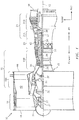
- FIG. 1 is a side cutaway illustration of a geared turbine engine 10.
- This turbine engine 10 extends along an axial centerline 12 between an upstream airflow inlet 14 and a downstream airflow exhaust 16.
- the turbine engine 10 includes a fan section 18, a compressor section 19, a combustor section 20 and a turbine section 21.
- the compressor section 19 includes a low pressure compressor (LPC) section 19A and a high pressure compressor (HPC) section 19B.
- the turbine section 21 includes a high pressure turbine (HPT) section 21A and a low pressure turbine (LPT) section 21B.
- the engine sections 18-21 are arranged sequentially along the centerline 12 within an engine housing 22.
- Each of the engine sections 18-19B, 21A and 21B includes a respective rotor 24-28.
- Each of these rotors 24-28 includes a plurality of rotor blades arranged circumferentially around and connected to one or more respective rotor disks.
- the rotor blades may be formed integral with or mechanically fastened, welded, brazed, adhered and/or otherwise attached to the respective rotor disk(s).
- the fan rotor 24 is connected to a gear train 30, for example, through a fan shaft 32.
- the gear train 30 and the LPC rotor 25 are connected to and driven by the LPT rotor 28 through a low speed shaft 33.
- the HPC rotor 26 is connected to and driven by the HPT rotor 27 through a high speed shaft 34.
- the shafts 32-34 are rotatably supported by a plurality of bearings 36; e.g., rolling element and/or thrust bearings. Each of these bearings 36 is connected to the engine housing 22 by at least one stationary structure such as, for example, an annular support strut.
- the air within the core gas path 38 may be referred to as "core air”.
- the air within the bypass gas path 40 may be referred to as "bypass air”.
- the core air is directed through the engine sections 19-21, and exits the turbine engine 10 through the airflow exhaust 16 to provide forward engine thrust.
- fuel is injected into a combustion chamber 42 and mixed with compressed core air. This fuel-core air mixture is ignited to power the turbine engine 10.
- the bypass air is directed through the bypass gas path 40 and out of the turbine engine 10 through a bypass nozzle 44 to provide additional forward engine thrust. This additional forward engine thrust may account for a majority (e.g., more than 70 percent) of total engine thrust.
- at least some of the bypass air may be directed out of the turbine engine 10 through a thrust reverser to provide reverse engine thrust.
- FIG. 1 represents one possible configuration for an engine 10. Aspects of the disclosure may be applied in connection with other environments, including additional configurations for gas turbine engines. Aspects of the disclosure may be applied in connection with non-geared engines.
- a system environment 200 is shown. At least a portion of the system 200 may be associated with a fixture as described below.
- the system 200 is shown as including a blade 202 having an airfoil 206.
- the blade 202 may be produced via a casting process.
- At least a portion of the blade 202, denoted by reference character 210, may be subject to machining. Examples include where the blade 202 is cast, with the airfoil 206 portion of the blade 202 formed with predefined geometric characteristics but other portions of the blade 202 require more precise dimensional characteristics and surface finish than a coating process can efficiently generate.
- the portion 210 may correspond to a root, an attachment, or a platform of the blade 202 used to precisely position the blade 202 relative to adjacent components.
- the blade 202 may be located within a medium 214 of a fixture.
- the medium 214 may include water that may have an associated melting-point temperature of approximately 32 degrees Fahrenheit (approximately 0 degrees Celsius).
- the medium 214 may include an injection molded material, such as for example a thermoplastic, a resin, a wax, etc.
- the medium 214 may include nylon or other polymer materials.
- the injection molded material may have a melting-point temperature within one or more temperatures ranges, such as for example a range of 200 degrees Fahrenheit (approximately 93 degrees Celsius) and 500 degrees Fahrenheit (approximately260 degrees Celsius).
- the use of an injection molded material for the medium 214 may allow the medium to tolerate higher loads than if water alone is used as the injection molded material may impart greater strength. Conversely, material removal machining techniques, including super abrasive machining, may be selected in order to minimize the induced loading on the fixture airfoil in an effort to more closely match the capability of the fixture.
- the medium 214 may be applied using one or more sources, such as for example the medium source 216.
- the fixture may include one or more gage pins 220.
- the pins 220 may be used to create a reference datum for locating the blade 202 within the fixture (e.g., the medium 214).
- the pins 220 may provide information regarding the orientation of the blade 202 in one or more spatial dimensions.
- the pins 220 may assist in providing a predetermined orientation to the blade 202 such that a toolset 230 associated with the machining operation may be fixed. Stated slightly differently, the pins 220 may ensure a particular orientation of the blade 202 in the fixture, such that the machining operation performed using the toolset 230 may be repeated for each instance of a blade 202 installed on the fixture.
- a scanning device 240 may be configured to scan the blade 202 when the blade 202 is installed on the fixture.
- the scanning device 240 may be operative on the basis of white light or the use of a laser.
- the scanning device 240 may respond to commands issued by a control computer 250 to scan the blade 202.
- Data acquired by the scanning device 240 (where the data may be based on absorption, reflection, diffraction, or other characteristics) may be provided to the control computer 250.
- the control computer 250 may process the data to determine an orientation of the blade 202 in the fixture. This determined orientation may be used by the control computer 250 to establish a set of control parameters that may be used to control the toolset 230.
- control computer 250 may establish the control parameters and control the toolset 230 in accordance therewith.
- the use of the scanning device 240 and/or the control computer 250 may represent an alternative to the use of pins 220.
- the use of the scanning device 240 and the control computer 250 may allow for an adaptation of the toolset 230 based on variations in the orientation of the blade 202 within the fixture.
- one or more sources 260 may be enabled/activated as part of a loop formed with, e.g., the medium 214, to cool the medium 214.
- the source 260 may include liquid nitrogen.
- the source 260 (or associated loop) may be enabled or disabled by the control computer 250.
- the determination of whether to enable or disable the source 260 may be based on the output of one or more sensors 270 coupled to the control computer 250.
- the sensors 270 may include one or more temperature sensors. The sensors 270 may be in contact with the blade 202 encased in the medium 214 to monitor heat transfer during machining.
- a coolant collar/heat sink 280 may be applied to the portion 210 in proximity to the interface between the portion 210 and the toolset 230.
- the heat sink 280 may deter or prevent a conductive heat transfer into the medium 214.
- any cooling that may have been provided by the source 260 or the heat sink 280 may be removed/disabled. If the melting-point of the medium 214 is less than, e.g., room temperature the medium may be allowed to sit/rest until the melting-point temperature is reached at which point the blade 202 may be extracted/removed from the fixture. Alternatively, if the melting-point temperature of the medium 214 is greater than room temperature or if there is a desire to accelerate the extraction of the blade 202 from the fixture, a source of heat may be applied to the medium 214. The source of heat may correspond to the source 260 (e.g., the same source 260 may be used to cool or heat the medium 214) or a separate, dedicated source.
- the source of heat may be operative on the basis of a thermal pad with resistive heaters that is applied to the medium 214.
- the source of heat may be controlled by the control computer 250; the control computer 250 may provide such control based on the output(s) of the sensor(s) 270.
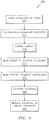
- the method 300 may be used to machine a component (e.g., the blade 202) using a toolset (e.g., toolset 230) via a fixture.
- a component e.g., the blade 202
- a toolset e.g., toolset 230
- the component may be installed on the fixture.
- a medium e.g., medium 214 of the fixture may be maintained in a liquid or semi-liquid state.
- the orientation of the component may be fixed (e.g., by the pins 220) and/or determined (e.g., via the scanning device 240 and the control computer 250).
- the medium may solidify to encase a portion of the component (e.g., the airfoil 206).
- one or more cooling sources e.g., source 260
- associated coolant loops may be enabled/activated to facilitate the solidification of the medium.
- a toolset (e.g., toolset 230) may be applied to at least a portion of the component (e.g., portion 210) to machine the component.
- the operation of the toolset may be adapted based on the orientation determined as part of block 312.
- one or more thermal mitigation techniques may be applied.
- a heat sink e.g., heat sink 280
- the component e.g., the portion 210
- a cooling source or associated coolant loop may be enabled/activated.
- the machining may be completed.
- any thermal mitigation techniques that may have been applied e.g., as part of block 330 may be removed.
- the medium may be allowed to transition from a solid to a liquid or semi-liquid state in order to allow the component to be extracted from the fixture.
- One or more sources of heat may be applied to the medium as part of block 342 to accelerate the extraction of the component.
- the blocks/operations associated with the method 300 are illustrative. In some embodiments, the blocks may execute in an order or sequence that is different from what is shown in FIG. 3 . In some embodiments, one or more of the blocks (or a portion thereof) may be optional.
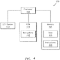
- the system 400 may be associated with one or more computers and/or one or more controllers (e.g., the control computer 250 of FIG. 2 ).
- the system 400 includes one or more processors (generally shown by a processor 402) and a memory 404.
- the memory 404 may store data 406 and/or instructions 408.
- the system 400 may include a computer-readable medium (CRM) 410 that may store some or all of the instructions 408.
- CRM 410 may include a transitory and/or a non-transitory computer-readable medium.
- the data 406 may include data obtained from one or more entities (e.g., the scanning device 240, the sensor 270).
- the data 406 may include results of processing the obtained data.
- the data 406 may include a specification of an orientation of a component (e.g., blade 202 of FIG. 2 ) within a fixture, where the specified orientation may map to parameters that may be used to control a machining operation or a toolset (e.g., toolset 230).
- the data 406 may be associated with one or more programs, such as a modeling or simulation program.
- the data may be native to or supported by one or more computed aided design or computer aided drawing programs, either one or both of which may be referred to as CAD programs.
- the data 406 may be used in connection with aligning a component and tooling.
- the system 400 may include one or more input/output (I/O) devices 412 that may be used to provide an interface between the system 400 and one or more additional systems or components.
- the I/O devices 412 may include one or more of a graphical user interface (GUI), a display screen, a touchscreen, a keyboard, a mouse, a joystick, a pushbutton, a microphone, a speaker, a transceiver, a sensor, etc.
- GUI graphical user interface
- machining operations facilitated by a fixture that is easier and cheaper to operate while also being more environmentally friendly/accommodating. Cycle times for machining components are reduced while providing a constant clamping load to resist vibration during machining.
- the use of a low melting-point medium reduces energy costs, lessens operator/technician exposure to elevated temperatures, and opens up additional, lower melting-points that may be used with the components being machined.
- water is used as the fixture medium, there is no appreciable chemical interaction between the medium and the component being machined and any residual water that may be on the component following the extraction of the component from the fixture will evaporate, thereby reducing any cleaning operations.
- Use of water as a medium also enables incorporation of other components (composite, injection molded thermoplastic, etc.) as part of a fixture, where those other components might not be thermally compatible with conventional low-melt alloy processes.
Landscapes
- Engineering & Computer Science (AREA)
- Mechanical Engineering (AREA)
- General Engineering & Computer Science (AREA)
- Architecture (AREA)
- Turbine Rotor Nozzle Sealing (AREA)
Applications Claiming Priority (1)
| Application Number | Priority Date | Filing Date | Title |
|---|---|---|---|
| US15/149,543 US10814445B2 (en) | 2016-05-09 | 2016-05-09 | Airfoil machining |
Publications (3)
| Publication Number | Publication Date |
|---|---|
| EP3243600A2 true EP3243600A2 (fr) | 2017-11-15 |
| EP3243600A3 EP3243600A3 (fr) | 2018-02-14 |
| EP3243600B1 EP3243600B1 (fr) | 2022-03-30 |
Family
ID=58701445
Family Applications (1)
| Application Number | Title | Priority Date | Filing Date |
|---|---|---|---|
| EP17170230.1A Active EP3243600B1 (fr) | 2016-05-09 | 2017-05-09 | Usinage de surface portante |
Country Status (2)
| Country | Link |
|---|---|
| US (1) | US10814445B2 (fr) |
| EP (1) | EP3243600B1 (fr) |
Cited By (1)
| Publication number | Priority date | Publication date | Assignee | Title |
|---|---|---|---|---|
| EP3456465A3 (fr) * | 2017-09-18 | 2019-03-27 | Rolls-Royce plc | Procédé de fixation d'une pièce pour opération d'usinage et ensemble moule pour une telle pièce |
Families Citing this family (6)
| Publication number | Priority date | Publication date | Assignee | Title |
|---|---|---|---|---|
| US11208892B2 (en) | 2020-01-17 | 2021-12-28 | Raytheon Technologies Corporation | Rotor assembly with multiple rotor disks |
| US11434771B2 (en) | 2020-01-17 | 2022-09-06 | Raytheon Technologies Corporation | Rotor blade pair for rotational equipment |
| US11401814B2 (en) | 2020-01-17 | 2022-08-02 | Raytheon Technologies Corporation | Rotor assembly with internal vanes |
| US11286781B2 (en) | 2020-01-17 | 2022-03-29 | Raytheon Technologies Corporation | Multi-disk bladed rotor assembly for rotational equipment |
| US11371351B2 (en) | 2020-01-17 | 2022-06-28 | Raytheon Technologies Corporation | Multi-disk bladed rotor assembly for rotational equipment |
| US11339673B2 (en) | 2020-01-17 | 2022-05-24 | Raytheon Technologies Corporation | Rotor assembly with internal vanes |
Family Cites Families (22)
| Publication number | Priority date | Publication date | Assignee | Title |
|---|---|---|---|---|
| US2722867A (en) | 1948-11-06 | 1955-11-08 | Thompson Prod Inc | Method of and apparatus for machining blade airfoil surfaces |
| US2641879A (en) | 1951-07-11 | 1953-06-16 | Internat Glass Company Inc | Mounting method |
| US2855664A (en) | 1955-12-21 | 1958-10-14 | Rohr Aircraft Corp | Method of machining honeycomb core |
| US4132689A (en) | 1977-10-03 | 1979-01-02 | Trw Inc. | Thermoplastic workholding composition and method of holding a workpiece |
| US4289191A (en) | 1980-04-02 | 1981-09-15 | United Technologies Corporation | Injection molding thermoplastic patterns having ceramic cores |
| DE3535809A1 (de) * | 1985-10-08 | 1987-04-09 | Hauni Werke Koerber & Co Kg | Halterungskoerper fuer werkstuecke, insbesondere turbinenschaufeln |
| GB2201106B (en) | 1986-12-11 | 1990-10-10 | Rolls Royce Plc | Apparatus and method of securing a component |
| US4873751A (en) | 1988-12-27 | 1989-10-17 | United Technologies Corporation | Fabrication or repair technique for integrally bladed rotor assembly |
| DE4129402A1 (de) | 1991-09-04 | 1993-03-11 | Blohm Maschinenbau Gmbh | Kuehlvorrichtung fuer eine schleifmaschine |
| US6329633B1 (en) | 1998-11-20 | 2001-12-11 | United Technologies Corporation | Method and material for processing a component for laser machining |
| JP2001009720A (ja) | 1999-06-22 | 2001-01-16 | Hitachi Seiki Co Ltd | 研削盤におけるクーラント供給方法およびその装置 |
| US6505678B2 (en) | 2001-04-17 | 2003-01-14 | Howmet Research Corporation | Ceramic core with locators and method |
| US7219408B2 (en) | 2002-09-24 | 2007-05-22 | General Electric Company | Tool for securing a component |
| TW590828B (en) * | 2002-12-12 | 2004-06-11 | Asia Optical Co Inc | Process for finishing an end surface of a non-circular post |
| US7328496B2 (en) | 2003-10-31 | 2008-02-12 | General Electric Company | Apparatus for rebuilding gas turbine engine blades |
| US20060168808A1 (en) * | 2005-02-03 | 2006-08-03 | United Technologies Corporation | Plasma ARC weld repair of IN100 material |
| EP1767743A1 (fr) * | 2005-09-26 | 2007-03-28 | Siemens Aktiengesellschaft | Méthode de fabrication d'un composant de turbine à gaz revêtu et ayant des ouvertures, dispositif pour l'application de ladite méthode et aube de turbine ayant des trous de refroidissement |
| FR2931379B1 (fr) | 2008-05-20 | 2010-12-10 | Sermas Ind | Dispositif de maintien d'un lingot pour la realisation de decoupes |
| CN103350213B (zh) | 2013-07-04 | 2016-09-07 | 常州市三维技术成套设备有限公司 | 汽轮机叶片加工中的低熔点合金浇铸定位工艺 |
| US20160265361A1 (en) * | 2015-03-12 | 2016-09-15 | General Electric Company | Machining tool positioning template for airfoil |
| US10016866B2 (en) * | 2015-05-20 | 2018-07-10 | The Boeing Company | Adjustable part holding fixture, system and method |
| US10252337B2 (en) * | 2016-08-29 | 2019-04-09 | Honeywell International Inc. | Methods for directionally recrystallizing additively-manufactured metallic articles by heat treatment with a gradient furnace |
-
2016
- 2016-05-09 US US15/149,543 patent/US10814445B2/en active Active
-
2017
- 2017-05-09 EP EP17170230.1A patent/EP3243600B1/fr active Active
Non-Patent Citations (1)
| Title |
|---|
| None |
Cited By (1)
| Publication number | Priority date | Publication date | Assignee | Title |
|---|---|---|---|---|
| EP3456465A3 (fr) * | 2017-09-18 | 2019-03-27 | Rolls-Royce plc | Procédé de fixation d'une pièce pour opération d'usinage et ensemble moule pour une telle pièce |
Also Published As
| Publication number | Publication date |
|---|---|
| EP3243600B1 (fr) | 2022-03-30 |
| US10814445B2 (en) | 2020-10-27 |
| EP3243600A3 (fr) | 2018-02-14 |
| US20170320178A1 (en) | 2017-11-09 |
Similar Documents
| Publication | Publication Date | Title |
|---|---|---|
| EP3243600B1 (fr) | Usinage de surface portante | |
| Bohn et al. | Conjugate flow and heat transfer investigation of a turbo charger | |
| Reitenbach et al. | Design and application of a multidisciplinary predesign process for novel engine concepts | |
| US12270308B2 (en) | Variable flowpath casings for blade tip clearance control | |
| CA2959708A1 (fr) | Methode et appareil de controle de degagement actif | |
| Spakovszky | Instabilities everywhere! hard problems in aero-engines | |
| Jeschke et al. | Preliminary gas turbine design using the multidisciplinary design system MOPEDS | |
| EP2998521A1 (fr) | Cotrôle actif et intelligent de jeu entre une pale de rotor et une virole | |
| Pekris et al. | An investigation of flow, mechanical, and thermal performance of conventional and pressure-balanced brush seals | |
| Crevel et al. | Numerical simulation of aerodynamic instabilities in a multistage high-speed high-pressure compressor on Its Test Rig—part II: deep surge | |
| Haldeman et al. | Aerodynamic and Heat Flux Measurements in a Single-Stage Fully Cooled Turbine—Part I: Experimental Approach | |
| EP4372231A1 (fr) | Pompes à compression-expansion doubles et procédés associés | |
| Wadia et al. | Aerodynamic design and testing of an axial flow compressor with pressure ratio of 23.3: 1 for the LM2500+ gas turbine | |
| Peng et al. | Cooling Injection Effect on the Suction Side Near-Tip Region of Turbine Blade With High-Speed Relative Casing Motion | |
| Okita et al. | Aerodynamic impact of secondary air injection flowrates on the main annulus flow field for a transonic high-pressure turbine stage | |
| CN120509231A (zh) | 一种跨尺度多物理场耦合的航空发动机暖机过程分析方法 | |
| Bretschneider et al. | Modeling of start-up from engine-off conditions using high fidelity turbofan engine simulations | |
| EP2971651B1 (fr) | Procédés de fonctionnement d'une turbine à gaz | |
| US12454894B1 (en) | Methods and apparatus to control a surface of an aircraft engine | |
| Lazzi Gazzini et al. | Effect of purge air on rotor endwall heat transfer of an axial turbine | |
| Corral et al. | On the transient behaviour of a laminar rotor–stator cavity | |
| Wang et al. | Impact investigation of inlet environmental changes on the rated condition performance of a high-pressure compressor | |
| US12577883B2 (en) | Blade tip clearance control using material with negative thermal expansion coefficients | |
| US11713733B2 (en) | Methods and systems for operating an engine to generate additional thrust | |
| Haslam et al. | A method for the assessment of operational severity for a high pressure turbine blade of an aero-engine |
Legal Events
| Date | Code | Title | Description |
|---|---|---|---|
| PUAI | Public reference made under article 153(3) epc to a published international application that has entered the european phase |
Free format text: ORIGINAL CODE: 0009012 |
|
| STAA | Information on the status of an ep patent application or granted ep patent |
Free format text: STATUS: THE APPLICATION HAS BEEN PUBLISHED |
|
| AK | Designated contracting states |
Kind code of ref document: A2 Designated state(s): AL AT BE BG CH CY CZ DE DK EE ES FI FR GB GR HR HU IE IS IT LI LT LU LV MC MK MT NL NO PL PT RO RS SE SI SK SM TR |
|
| AX | Request for extension of the european patent |
Extension state: BA ME |
|
| PUAL | Search report despatched |
Free format text: ORIGINAL CODE: 0009013 |
|
| AK | Designated contracting states |
Kind code of ref document: A3 Designated state(s): AL AT BE BG CH CY CZ DE DK EE ES FI FR GB GR HR HU IE IS IT LI LT LU LV MC MK MT NL NO PL PT RO RS SE SI SK SM TR |
|
| AX | Request for extension of the european patent |
Extension state: BA ME |
|
| RIC1 | Information provided on ipc code assigned before grant |
Ipc: B23Q 3/06 20060101AFI20180110BHEP Ipc: B23Q 3/08 20060101ALI20180110BHEP |
|
| STAA | Information on the status of an ep patent application or granted ep patent |
Free format text: STATUS: REQUEST FOR EXAMINATION WAS MADE |
|
| 17P | Request for examination filed |
Effective date: 20180814 |
|
| RBV | Designated contracting states (corrected) |
Designated state(s): AL AT BE BG CH CY CZ DE DK EE ES FI FR GB GR HR HU IE IS IT LI LT LU LV MC MK MT NL NO PL PT RO RS SE SI SK SM TR |
|
| STAA | Information on the status of an ep patent application or granted ep patent |
Free format text: STATUS: EXAMINATION IS IN PROGRESS |
|
| 17Q | First examination report despatched |
Effective date: 20201112 |
|
| RAP1 | Party data changed (applicant data changed or rights of an application transferred) |
Owner name: RAYTHEON TECHNOLOGIES CORPORATION |
|
| GRAP | Despatch of communication of intention to grant a patent |
Free format text: ORIGINAL CODE: EPIDOSNIGR1 |
|
| STAA | Information on the status of an ep patent application or granted ep patent |
Free format text: STATUS: GRANT OF PATENT IS INTENDED |
|
| GRAJ | Information related to disapproval of communication of intention to grant by the applicant or resumption of examination proceedings by the epo deleted |
Free format text: ORIGINAL CODE: EPIDOSDIGR1 |
|
| GRAP | Despatch of communication of intention to grant a patent |
Free format text: ORIGINAL CODE: EPIDOSNIGR1 |
|
| INTG | Intention to grant announced |
Effective date: 20211013 |
|
| INTG | Intention to grant announced |
Effective date: 20211026 |
|
| GRAS | Grant fee paid |
Free format text: ORIGINAL CODE: EPIDOSNIGR3 |
|
| GRAA | (expected) grant |
Free format text: ORIGINAL CODE: 0009210 |
|
| STAA | Information on the status of an ep patent application or granted ep patent |
Free format text: STATUS: THE PATENT HAS BEEN GRANTED |
|
| AK | Designated contracting states |
Kind code of ref document: B1 Designated state(s): AL AT BE BG CH CY CZ DE DK EE ES FI FR GB GR HR HU IE IS IT LI LT LU LV MC MK MT NL NO PL PT RO RS SE SI SK SM TR |
|
| REG | Reference to a national code |
Ref country code: GB Ref legal event code: FG4D |
|
| REG | Reference to a national code |
Ref country code: CH Ref legal event code: EP |
|
| REG | Reference to a national code |
Ref country code: AT Ref legal event code: REF Ref document number: 1478728 Country of ref document: AT Kind code of ref document: T Effective date: 20220415 |
|
| REG | Reference to a national code |
Ref country code: DE Ref legal event code: R096 Ref document number: 602017055124 Country of ref document: DE |
|
| REG | Reference to a national code |
Ref country code: IE Ref legal event code: FG4D |
|
| REG | Reference to a national code |
Ref country code: LT Ref legal event code: MG9D |
|
| PG25 | Lapsed in a contracting state [announced via postgrant information from national office to epo] |
Ref country code: SE Free format text: LAPSE BECAUSE OF FAILURE TO SUBMIT A TRANSLATION OF THE DESCRIPTION OR TO PAY THE FEE WITHIN THE PRESCRIBED TIME-LIMIT Effective date: 20220330 Ref country code: RS Free format text: LAPSE BECAUSE OF FAILURE TO SUBMIT A TRANSLATION OF THE DESCRIPTION OR TO PAY THE FEE WITHIN THE PRESCRIBED TIME-LIMIT Effective date: 20220330 Ref country code: NO Free format text: LAPSE BECAUSE OF FAILURE TO SUBMIT A TRANSLATION OF THE DESCRIPTION OR TO PAY THE FEE WITHIN THE PRESCRIBED TIME-LIMIT Effective date: 20220630 Ref country code: LT Free format text: LAPSE BECAUSE OF FAILURE TO SUBMIT A TRANSLATION OF THE DESCRIPTION OR TO PAY THE FEE WITHIN THE PRESCRIBED TIME-LIMIT Effective date: 20220330 Ref country code: HR Free format text: LAPSE BECAUSE OF FAILURE TO SUBMIT A TRANSLATION OF THE DESCRIPTION OR TO PAY THE FEE WITHIN THE PRESCRIBED TIME-LIMIT Effective date: 20220330 Ref country code: BG Free format text: LAPSE BECAUSE OF FAILURE TO SUBMIT A TRANSLATION OF THE DESCRIPTION OR TO PAY THE FEE WITHIN THE PRESCRIBED TIME-LIMIT Effective date: 20220630 |
|
| REG | Reference to a national code |
Ref country code: NL Ref legal event code: MP Effective date: 20220330 |
|
| REG | Reference to a national code |
Ref country code: AT Ref legal event code: MK05 Ref document number: 1478728 Country of ref document: AT Kind code of ref document: T Effective date: 20220330 |
|
| PG25 | Lapsed in a contracting state [announced via postgrant information from national office to epo] |
Ref country code: LV Free format text: LAPSE BECAUSE OF FAILURE TO SUBMIT A TRANSLATION OF THE DESCRIPTION OR TO PAY THE FEE WITHIN THE PRESCRIBED TIME-LIMIT Effective date: 20220330 Ref country code: GR Free format text: LAPSE BECAUSE OF FAILURE TO SUBMIT A TRANSLATION OF THE DESCRIPTION OR TO PAY THE FEE WITHIN THE PRESCRIBED TIME-LIMIT Effective date: 20220701 Ref country code: FI Free format text: LAPSE BECAUSE OF FAILURE TO SUBMIT A TRANSLATION OF THE DESCRIPTION OR TO PAY THE FEE WITHIN THE PRESCRIBED TIME-LIMIT Effective date: 20220330 |
|
| PG25 | Lapsed in a contracting state [announced via postgrant information from national office to epo] |
Ref country code: NL Free format text: LAPSE BECAUSE OF FAILURE TO SUBMIT A TRANSLATION OF THE DESCRIPTION OR TO PAY THE FEE WITHIN THE PRESCRIBED TIME-LIMIT Effective date: 20220330 |
|
| PG25 | Lapsed in a contracting state [announced via postgrant information from national office to epo] |
Ref country code: SM Free format text: LAPSE BECAUSE OF FAILURE TO SUBMIT A TRANSLATION OF THE DESCRIPTION OR TO PAY THE FEE WITHIN THE PRESCRIBED TIME-LIMIT Effective date: 20220330 Ref country code: SK Free format text: LAPSE BECAUSE OF FAILURE TO SUBMIT A TRANSLATION OF THE DESCRIPTION OR TO PAY THE FEE WITHIN THE PRESCRIBED TIME-LIMIT Effective date: 20220330 Ref country code: RO Free format text: LAPSE BECAUSE OF FAILURE TO SUBMIT A TRANSLATION OF THE DESCRIPTION OR TO PAY THE FEE WITHIN THE PRESCRIBED TIME-LIMIT Effective date: 20220330 Ref country code: PT Free format text: LAPSE BECAUSE OF FAILURE TO SUBMIT A TRANSLATION OF THE DESCRIPTION OR TO PAY THE FEE WITHIN THE PRESCRIBED TIME-LIMIT Effective date: 20220801 Ref country code: ES Free format text: LAPSE BECAUSE OF FAILURE TO SUBMIT A TRANSLATION OF THE DESCRIPTION OR TO PAY THE FEE WITHIN THE PRESCRIBED TIME-LIMIT Effective date: 20220330 Ref country code: EE Free format text: LAPSE BECAUSE OF FAILURE TO SUBMIT A TRANSLATION OF THE DESCRIPTION OR TO PAY THE FEE WITHIN THE PRESCRIBED TIME-LIMIT Effective date: 20220330 Ref country code: CZ Free format text: LAPSE BECAUSE OF FAILURE TO SUBMIT A TRANSLATION OF THE DESCRIPTION OR TO PAY THE FEE WITHIN THE PRESCRIBED TIME-LIMIT Effective date: 20220330 Ref country code: AT Free format text: LAPSE BECAUSE OF FAILURE TO SUBMIT A TRANSLATION OF THE DESCRIPTION OR TO PAY THE FEE WITHIN THE PRESCRIBED TIME-LIMIT Effective date: 20220330 |
|
| PG25 | Lapsed in a contracting state [announced via postgrant information from national office to epo] |
Ref country code: PL Free format text: LAPSE BECAUSE OF FAILURE TO SUBMIT A TRANSLATION OF THE DESCRIPTION OR TO PAY THE FEE WITHIN THE PRESCRIBED TIME-LIMIT Effective date: 20220330 Ref country code: IS Free format text: LAPSE BECAUSE OF FAILURE TO SUBMIT A TRANSLATION OF THE DESCRIPTION OR TO PAY THE FEE WITHIN THE PRESCRIBED TIME-LIMIT Effective date: 20220730 Ref country code: AL Free format text: LAPSE BECAUSE OF FAILURE TO SUBMIT A TRANSLATION OF THE DESCRIPTION OR TO PAY THE FEE WITHIN THE PRESCRIBED TIME-LIMIT Effective date: 20220330 |
|
| REG | Reference to a national code |
Ref country code: CH Ref legal event code: PL |
|
| REG | Reference to a national code |
Ref country code: DE Ref legal event code: R097 Ref document number: 602017055124 Country of ref document: DE |
|
| REG | Reference to a national code |
Ref country code: BE Ref legal event code: MM Effective date: 20220531 |
|
| PG25 | Lapsed in a contracting state [announced via postgrant information from national office to epo] |
Ref country code: MC Free format text: LAPSE BECAUSE OF FAILURE TO SUBMIT A TRANSLATION OF THE DESCRIPTION OR TO PAY THE FEE WITHIN THE PRESCRIBED TIME-LIMIT Effective date: 20220330 Ref country code: LU Free format text: LAPSE BECAUSE OF NON-PAYMENT OF DUE FEES Effective date: 20220509 Ref country code: LI Free format text: LAPSE BECAUSE OF NON-PAYMENT OF DUE FEES Effective date: 20220531 Ref country code: DK Free format text: LAPSE BECAUSE OF FAILURE TO SUBMIT A TRANSLATION OF THE DESCRIPTION OR TO PAY THE FEE WITHIN THE PRESCRIBED TIME-LIMIT Effective date: 20220330 Ref country code: CH Free format text: LAPSE BECAUSE OF NON-PAYMENT OF DUE FEES Effective date: 20220531 |
|
| PLBE | No opposition filed within time limit |
Free format text: ORIGINAL CODE: 0009261 |
|
| STAA | Information on the status of an ep patent application or granted ep patent |
Free format text: STATUS: NO OPPOSITION FILED WITHIN TIME LIMIT |
|
| 26N | No opposition filed |
Effective date: 20230103 |
|
| PG25 | Lapsed in a contracting state [announced via postgrant information from national office to epo] |
Ref country code: IE Free format text: LAPSE BECAUSE OF NON-PAYMENT OF DUE FEES Effective date: 20220509 |
|
| PG25 | Lapsed in a contracting state [announced via postgrant information from national office to epo] |
Ref country code: SI Free format text: LAPSE BECAUSE OF FAILURE TO SUBMIT A TRANSLATION OF THE DESCRIPTION OR TO PAY THE FEE WITHIN THE PRESCRIBED TIME-LIMIT Effective date: 20220330 Ref country code: BE Free format text: LAPSE BECAUSE OF NON-PAYMENT OF DUE FEES Effective date: 20220531 |
|
| P01 | Opt-out of the competence of the unified patent court (upc) registered |
Effective date: 20230520 |
|
| PG25 | Lapsed in a contracting state [announced via postgrant information from national office to epo] |
Ref country code: IT Free format text: LAPSE BECAUSE OF FAILURE TO SUBMIT A TRANSLATION OF THE DESCRIPTION OR TO PAY THE FEE WITHIN THE PRESCRIBED TIME-LIMIT Effective date: 20220330 |
|
| PG25 | Lapsed in a contracting state [announced via postgrant information from national office to epo] |
Ref country code: HU Free format text: LAPSE BECAUSE OF FAILURE TO SUBMIT A TRANSLATION OF THE DESCRIPTION OR TO PAY THE FEE WITHIN THE PRESCRIBED TIME-LIMIT; INVALID AB INITIO Effective date: 20170509 |
|
| PG25 | Lapsed in a contracting state [announced via postgrant information from national office to epo] |
Ref country code: MK Free format text: LAPSE BECAUSE OF FAILURE TO SUBMIT A TRANSLATION OF THE DESCRIPTION OR TO PAY THE FEE WITHIN THE PRESCRIBED TIME-LIMIT Effective date: 20220330 Ref country code: CY Free format text: LAPSE BECAUSE OF FAILURE TO SUBMIT A TRANSLATION OF THE DESCRIPTION OR TO PAY THE FEE WITHIN THE PRESCRIBED TIME-LIMIT Effective date: 20220330 |
|
| PG25 | Lapsed in a contracting state [announced via postgrant information from national office to epo] |
Ref country code: MT Free format text: LAPSE BECAUSE OF FAILURE TO SUBMIT A TRANSLATION OF THE DESCRIPTION OR TO PAY THE FEE WITHIN THE PRESCRIBED TIME-LIMIT Effective date: 20220330 |
|
| PGFP | Annual fee paid to national office [announced via postgrant information from national office to epo] |
Ref country code: DE Payment date: 20250423 Year of fee payment: 9 |
|
| PGFP | Annual fee paid to national office [announced via postgrant information from national office to epo] |
Ref country code: GB Payment date: 20250423 Year of fee payment: 9 |
|
| PGFP | Annual fee paid to national office [announced via postgrant information from national office to epo] |
Ref country code: FR Payment date: 20250423 Year of fee payment: 9 |
|
| REG | Reference to a national code |
Ref country code: DE Ref legal event code: R081 Ref document number: 602017055124 Country of ref document: DE Owner name: RTX CORPORATION (N.D.GES.D. STAATES DELAWARE),, US Free format text: FORMER OWNER: RAYTHEON TECHNOLOGIES CORPORATION, FARMINGTON, CT, US |
|
| PG25 | Lapsed in a contracting state [announced via postgrant information from national office to epo] |
Ref country code: TR Free format text: LAPSE BECAUSE OF FAILURE TO SUBMIT A TRANSLATION OF THE DESCRIPTION OR TO PAY THE FEE WITHIN THE PRESCRIBED TIME-LIMIT Effective date: 20220330 |