EP3243640A2 - Moule pour matériau renforcé de fibres et procédé correspondant - Google Patents
Moule pour matériau renforcé de fibres et procédé correspondant Download PDFInfo
- Publication number
- EP3243640A2 EP3243640A2 EP17155243.3A EP17155243A EP3243640A2 EP 3243640 A2 EP3243640 A2 EP 3243640A2 EP 17155243 A EP17155243 A EP 17155243A EP 3243640 A2 EP3243640 A2 EP 3243640A2
- Authority
- EP
- European Patent Office
- Prior art keywords
- composite material
- optical fiber
- groove
- fiber sensor
- convex portion
- Prior art date
- Legal status (The legal status is an assumption and is not a legal conclusion. Google has not performed a legal analysis and makes no representation as to the accuracy of the status listed.)
- Granted
Links
Images





Classifications
-
- G—PHYSICS
- G01—MEASURING; TESTING
- G01N—INVESTIGATING OR ANALYSING MATERIALS BY DETERMINING THEIR CHEMICAL OR PHYSICAL PROPERTIES
- G01N29/00—Investigating or analysing materials by the use of ultrasonic, sonic or infrasonic waves; Visualisation of the interior of objects by transmitting ultrasonic or sonic waves through the object
- G01N29/04—Analysing solids
-
- G—PHYSICS
- G01—MEASURING; TESTING
- G01N—INVESTIGATING OR ANALYSING MATERIALS BY DETERMINING THEIR CHEMICAL OR PHYSICAL PROPERTIES
- G01N29/00—Investigating or analysing materials by the use of ultrasonic, sonic or infrasonic waves; Visualisation of the interior of objects by transmitting ultrasonic or sonic waves through the object
- G01N29/22—Details, e.g. general constructional or apparatus details
- G01N29/24—Probes
- G01N29/2418—Probes using optoacoustic interaction with the material, e.g. laser radiation, photoacoustics
-
- B—PERFORMING OPERATIONS; TRANSPORTING
- B29—WORKING OF PLASTICS; WORKING OF SUBSTANCES IN A PLASTIC STATE IN GENERAL
- B29C—SHAPING OR JOINING OF PLASTICS; SHAPING OF MATERIAL IN A PLASTIC STATE, NOT OTHERWISE PROVIDED FOR; AFTER-TREATMENT OF THE SHAPED PRODUCTS, e.g. REPAIRING
- B29C43/00—Compression moulding, i.e. applying external pressure to flow the moulding material; Apparatus therefor
- B29C43/32—Component parts, details or accessories; Auxiliary operations
- B29C43/58—Measuring, controlling or regulating
-
- B—PERFORMING OPERATIONS; TRANSPORTING
- B29—WORKING OF PLASTICS; WORKING OF SUBSTANCES IN A PLASTIC STATE IN GENERAL
- B29C—SHAPING OR JOINING OF PLASTICS; SHAPING OF MATERIAL IN A PLASTIC STATE, NOT OTHERWISE PROVIDED FOR; AFTER-TREATMENT OF THE SHAPED PRODUCTS, e.g. REPAIRING
- B29C59/00—Surface shaping of articles, e.g. embossing; Apparatus therefor
- B29C59/02—Surface shaping of articles, e.g. embossing; Apparatus therefor by mechanical means, e.g. pressing
- B29C59/022—Surface shaping of articles, e.g. embossing; Apparatus therefor by mechanical means, e.g. pressing characterised by the disposition or the configuration, e.g. dimensions, of the embossments or the shaping tools therefor
-
- B—PERFORMING OPERATIONS; TRANSPORTING
- B29—WORKING OF PLASTICS; WORKING OF SUBSTANCES IN A PLASTIC STATE IN GENERAL
- B29C—SHAPING OR JOINING OF PLASTICS; SHAPING OF MATERIAL IN A PLASTIC STATE, NOT OTHERWISE PROVIDED FOR; AFTER-TREATMENT OF THE SHAPED PRODUCTS, e.g. REPAIRING
- B29C59/00—Surface shaping of articles, e.g. embossing; Apparatus therefor
- B29C59/02—Surface shaping of articles, e.g. embossing; Apparatus therefor by mechanical means, e.g. pressing
- B29C59/026—Surface shaping of articles, e.g. embossing; Apparatus therefor by mechanical means, e.g. pressing of layered or coated substantially flat surfaces
-
- B—PERFORMING OPERATIONS; TRANSPORTING
- B29—WORKING OF PLASTICS; WORKING OF SUBSTANCES IN A PLASTIC STATE IN GENERAL
- B29C—SHAPING OR JOINING OF PLASTICS; SHAPING OF MATERIAL IN A PLASTIC STATE, NOT OTHERWISE PROVIDED FOR; AFTER-TREATMENT OF THE SHAPED PRODUCTS, e.g. REPAIRING
- B29C65/00—Joining or sealing of preformed parts, e.g. welding of plastics materials; Apparatus therefor
- B29C65/48—Joining or sealing of preformed parts, e.g. welding of plastics materials; Apparatus therefor using adhesives, i.e. using supplementary joining material; solvent bonding
- B29C65/4855—Joining or sealing of preformed parts, e.g. welding of plastics materials; Apparatus therefor using adhesives, i.e. using supplementary joining material; solvent bonding characterised by their physical properties, e.g. being electrically-conductive
-
- B—PERFORMING OPERATIONS; TRANSPORTING
- B29—WORKING OF PLASTICS; WORKING OF SUBSTANCES IN A PLASTIC STATE IN GENERAL
- B29C—SHAPING OR JOINING OF PLASTICS; SHAPING OF MATERIAL IN A PLASTIC STATE, NOT OTHERWISE PROVIDED FOR; AFTER-TREATMENT OF THE SHAPED PRODUCTS, e.g. REPAIRING
- B29C70/00—Shaping composites, i.e. plastics material comprising reinforcements, fillers or preformed parts, e.g. inserts
- B29C70/04—Shaping composites, i.e. plastics material comprising reinforcements, fillers or preformed parts, e.g. inserts comprising reinforcements only, e.g. self-reinforcing plastics
- B29C70/28—Shaping operations therefor
- B29C70/30—Shaping by lay-up, i.e. applying fibres, tape or broadsheet on a mould, former or core; Shaping by spray-up, i.e. spraying of fibres on a mould, former or core
- B29C70/34—Shaping by lay-up, i.e. applying fibres, tape or broadsheet on a mould, former or core; Shaping by spray-up, i.e. spraying of fibres on a mould, former or core and shaping or impregnating by compression, i.e. combined with compressing after the lay-up operation
-
- B—PERFORMING OPERATIONS; TRANSPORTING
- B29—WORKING OF PLASTICS; WORKING OF SUBSTANCES IN A PLASTIC STATE IN GENERAL
- B29C—SHAPING OR JOINING OF PLASTICS; SHAPING OF MATERIAL IN A PLASTIC STATE, NOT OTHERWISE PROVIDED FOR; AFTER-TREATMENT OF THE SHAPED PRODUCTS, e.g. REPAIRING
- B29C70/00—Shaping composites, i.e. plastics material comprising reinforcements, fillers or preformed parts, e.g. inserts
- B29C70/04—Shaping composites, i.e. plastics material comprising reinforcements, fillers or preformed parts, e.g. inserts comprising reinforcements only, e.g. self-reinforcing plastics
- B29C70/28—Shaping operations therefor
- B29C70/40—Shaping or impregnating by compression not applied
- B29C70/42—Shaping or impregnating by compression not applied for producing articles of definite length, i.e. discrete articles
-
- B—PERFORMING OPERATIONS; TRANSPORTING
- B32—LAYERED PRODUCTS
- B32B—LAYERED PRODUCTS, i.e. PRODUCTS BUILT-UP OF STRATA OF FLAT OR NON-FLAT, e.g. CELLULAR OR HONEYCOMB, FORM
- B32B27/00—Layered products comprising a layer of synthetic resin
-
- B—PERFORMING OPERATIONS; TRANSPORTING
- B32—LAYERED PRODUCTS
- B32B—LAYERED PRODUCTS, i.e. PRODUCTS BUILT-UP OF STRATA OF FLAT OR NON-FLAT, e.g. CELLULAR OR HONEYCOMB, FORM
- B32B37/00—Methods or apparatus for laminating, e.g. by curing or by ultrasonic bonding
- B32B37/12—Methods or apparatus for laminating, e.g. by curing or by ultrasonic bonding characterised by using adhesives
-
- B—PERFORMING OPERATIONS; TRANSPORTING
- B32—LAYERED PRODUCTS
- B32B—LAYERED PRODUCTS, i.e. PRODUCTS BUILT-UP OF STRATA OF FLAT OR NON-FLAT, e.g. CELLULAR OR HONEYCOMB, FORM
- B32B5/00—Layered products characterised by the non- homogeneity or physical structure, i.e. comprising a fibrous, filamentary, particulate or foam layer; Layered products characterised by having a layer differing constitutionally or physically in different parts
- B32B5/02—Layered products characterised by the non- homogeneity or physical structure, i.e. comprising a fibrous, filamentary, particulate or foam layer; Layered products characterised by having a layer differing constitutionally or physically in different parts characterised by structural features of a fibrous or filamentary layer
- B32B5/10—Layered products characterised by the non- homogeneity or physical structure, i.e. comprising a fibrous, filamentary, particulate or foam layer; Layered products characterised by having a layer differing constitutionally or physically in different parts characterised by structural features of a fibrous or filamentary layer characterised by a fibrous or filamentary layer reinforced with filaments
-
- B—PERFORMING OPERATIONS; TRANSPORTING
- B32—LAYERED PRODUCTS
- B32B—LAYERED PRODUCTS, i.e. PRODUCTS BUILT-UP OF STRATA OF FLAT OR NON-FLAT, e.g. CELLULAR OR HONEYCOMB, FORM
- B32B7/00—Layered products characterised by the relation between layers; Layered products characterised by the relative orientation of features between layers, or by the relative values of a measurable parameter between layers, i.e. products comprising layers having different physical, chemical or physicochemical properties; Layered products characterised by the interconnection of layers
- B32B7/04—Interconnection of layers
- B32B7/12—Interconnection of layers using interposed adhesives or interposed materials with bonding properties
-
- B—PERFORMING OPERATIONS; TRANSPORTING
- B64—AIRCRAFT; AVIATION; COSMONAUTICS
- B64C—AEROPLANES; HELICOPTERS
- B64C3/00—Wings
- B64C3/18—Spars; Ribs; Stringers
-
- G—PHYSICS
- G01—MEASURING; TESTING
- G01N—INVESTIGATING OR ANALYSING MATERIALS BY DETERMINING THEIR CHEMICAL OR PHYSICAL PROPERTIES
- G01N29/00—Investigating or analysing materials by the use of ultrasonic, sonic or infrasonic waves; Visualisation of the interior of objects by transmitting ultrasonic or sonic waves through the object
- G01N29/04—Analysing solids
- G01N29/043—Analysing solids in the interior, e.g. by shear waves
-
- B—PERFORMING OPERATIONS; TRANSPORTING
- B29—WORKING OF PLASTICS; WORKING OF SUBSTANCES IN A PLASTIC STATE IN GENERAL
- B29C—SHAPING OR JOINING OF PLASTICS; SHAPING OF MATERIAL IN A PLASTIC STATE, NOT OTHERWISE PROVIDED FOR; AFTER-TREATMENT OF THE SHAPED PRODUCTS, e.g. REPAIRING
- B29C33/00—Moulds or cores; Details thereof or accessories therefor
- B29C2033/0094—Means for masking a part of the moulding surface
-
- B—PERFORMING OPERATIONS; TRANSPORTING
- B29—WORKING OF PLASTICS; WORKING OF SUBSTANCES IN A PLASTIC STATE IN GENERAL
- B29C—SHAPING OR JOINING OF PLASTICS; SHAPING OF MATERIAL IN A PLASTIC STATE, NOT OTHERWISE PROVIDED FOR; AFTER-TREATMENT OF THE SHAPED PRODUCTS, e.g. REPAIRING
- B29C43/00—Compression moulding, i.e. applying external pressure to flow the moulding material; Apparatus therefor
- B29C43/32—Component parts, details or accessories; Auxiliary operations
- B29C43/58—Measuring, controlling or regulating
- B29C2043/5808—Measuring, controlling or regulating pressure or compressing force
-
- B—PERFORMING OPERATIONS; TRANSPORTING
- B29—WORKING OF PLASTICS; WORKING OF SUBSTANCES IN A PLASTIC STATE IN GENERAL
- B29C—SHAPING OR JOINING OF PLASTICS; SHAPING OF MATERIAL IN A PLASTIC STATE, NOT OTHERWISE PROVIDED FOR; AFTER-TREATMENT OF THE SHAPED PRODUCTS, e.g. REPAIRING
- B29C33/00—Moulds or cores; Details thereof or accessories therefor
- B29C33/42—Moulds or cores; Details thereof or accessories therefor characterised by the shape of the moulding surface, e.g. ribs or grooves
-
- B—PERFORMING OPERATIONS; TRANSPORTING
- B29—WORKING OF PLASTICS; WORKING OF SUBSTANCES IN A PLASTIC STATE IN GENERAL
- B29C—SHAPING OR JOINING OF PLASTICS; SHAPING OF MATERIAL IN A PLASTIC STATE, NOT OTHERWISE PROVIDED FOR; AFTER-TREATMENT OF THE SHAPED PRODUCTS, e.g. REPAIRING
- B29C43/00—Compression moulding, i.e. applying external pressure to flow the moulding material; Apparatus therefor
- B29C43/02—Compression moulding, i.e. applying external pressure to flow the moulding material; Apparatus therefor of articles of definite length, i.e. discrete articles
- B29C43/021—Compression moulding, i.e. applying external pressure to flow the moulding material; Apparatus therefor of articles of definite length, i.e. discrete articles characterised by the shape of the surface
-
- B—PERFORMING OPERATIONS; TRANSPORTING
- B29—WORKING OF PLASTICS; WORKING OF SUBSTANCES IN A PLASTIC STATE IN GENERAL
- B29K—INDEXING SCHEME ASSOCIATED WITH SUBCLASSES B29B, B29C OR B29D, RELATING TO MOULDING MATERIALS OR TO MATERIALS FOR MOULDS, REINFORCEMENTS, FILLERS OR PREFORMED PARTS, e.g. INSERTS
- B29K2105/00—Condition, form or state of moulded material or of the material to be shaped
- B29K2105/06—Condition, form or state of moulded material or of the material to be shaped containing reinforcements, fillers or inserts
-
- B—PERFORMING OPERATIONS; TRANSPORTING
- B29—WORKING OF PLASTICS; WORKING OF SUBSTANCES IN A PLASTIC STATE IN GENERAL
- B29K—INDEXING SCHEME ASSOCIATED WITH SUBCLASSES B29B, B29C OR B29D, RELATING TO MOULDING MATERIALS OR TO MATERIALS FOR MOULDS, REINFORCEMENTS, FILLERS OR PREFORMED PARTS, e.g. INSERTS
- B29K2995/00—Properties of moulding materials, reinforcements, fillers, preformed parts or moulds
- B29K2995/0001—Properties of moulding materials, reinforcements, fillers, preformed parts or moulds having particular acoustical properties
-
- B—PERFORMING OPERATIONS; TRANSPORTING
- B29—WORKING OF PLASTICS; WORKING OF SUBSTANCES IN A PLASTIC STATE IN GENERAL
- B29L—INDEXING SCHEME ASSOCIATED WITH SUBCLASS B29C, RELATING TO PARTICULAR ARTICLES
- B29L2031/00—Other particular articles
- B29L2031/30—Vehicles, e.g. ships or aircraft, or body parts thereof
- B29L2031/3076—Aircrafts
-
- B—PERFORMING OPERATIONS; TRANSPORTING
- B29—WORKING OF PLASTICS; WORKING OF SUBSTANCES IN A PLASTIC STATE IN GENERAL
- B29L—INDEXING SCHEME ASSOCIATED WITH SUBCLASS B29C, RELATING TO PARTICULAR ARTICLES
- B29L2031/00—Other particular articles
- B29L2031/30—Vehicles, e.g. ships or aircraft, or body parts thereof
- B29L2031/3076—Aircrafts
- B29L2031/3082—Fuselages
-
- B—PERFORMING OPERATIONS; TRANSPORTING
- B32—LAYERED PRODUCTS
- B32B—LAYERED PRODUCTS, i.e. PRODUCTS BUILT-UP OF STRATA OF FLAT OR NON-FLAT, e.g. CELLULAR OR HONEYCOMB, FORM
- B32B2307/00—Properties of the layers or laminate
- B32B2307/10—Properties of the layers or laminate having particular acoustical properties
-
- B—PERFORMING OPERATIONS; TRANSPORTING
- B32—LAYERED PRODUCTS
- B32B—LAYERED PRODUCTS, i.e. PRODUCTS BUILT-UP OF STRATA OF FLAT OR NON-FLAT, e.g. CELLULAR OR HONEYCOMB, FORM
- B32B2605/00—Vehicles
- B32B2605/18—Aircraft
-
- G—PHYSICS
- G01—MEASURING; TESTING
- G01N—INVESTIGATING OR ANALYSING MATERIALS BY DETERMINING THEIR CHEMICAL OR PHYSICAL PROPERTIES
- G01N2291/00—Indexing codes associated with group G01N29/00
- G01N2291/02—Indexing codes associated with the analysed material
- G01N2291/028—Material parameters
- G01N2291/0289—Internal structure, e.g. defects, grain size, texture
-
- Y—GENERAL TAGGING OF NEW TECHNOLOGICAL DEVELOPMENTS; GENERAL TAGGING OF CROSS-SECTIONAL TECHNOLOGIES SPANNING OVER SEVERAL SECTIONS OF THE IPC; TECHNICAL SUBJECTS COVERED BY FORMER USPC CROSS-REFERENCE ART COLLECTIONS [XRACs] AND DIGESTS
- Y02—TECHNOLOGIES OR APPLICATIONS FOR MITIGATION OR ADAPTATION AGAINST CLIMATE CHANGE
- Y02T—CLIMATE CHANGE MITIGATION TECHNOLOGIES RELATED TO TRANSPORTATION
- Y02T50/00—Aeronautics or air transport
- Y02T50/40—Weight reduction
Definitions
- Embodiments described herein relate generally to a composite material molding jig, a composite material molding method, an ultrasonic test system, an ultrasonic test method and an aircraft structural object.
- ultrasonography is known as a method of nondestructively testing a structural member of an aircraft or the like.
- a technique using an FBG (fiber Bragg grating) sensor as a sensor for ultrasonic testing is also known.
- FBG fiber Bragg grating
- Using an FBG sensor as a sensor for receiving an ultrasonic wave can improve detection accuracy of ultrasonic waves compared to a case where an ultrasonic transducer is used as the sensor.
- a composite material such as GFRP (glass fiber reinforced plastics) or CFRP (carbon fiber reinforced plastics), which is lightweight and has high strengths, has attracted attention mainly as a material of an aircraft structural object or the like.
- a composite material is manufactured by laminating and curing semi-cured sheet-like prepregs, each of which made of fibers, such as carbon fibers or glass fibers, impregnated with resin.
- a technique of embedding an optical fiber, as a strain sensor, between sheet-like prepregs, which are a material before curing of a composite material, and then, curing the prepregs between which the optical fiber is embedded has been proposed (for example, refer to Japanese Patent Application Publication JP 2012-020483 A and Japanese Patent Application Publication JP H11-142262 A ).
- a composite material, in which an optical fiber has been embedded can be manufactured by inserting the optical fiber between prepreg sheets during laminating the prepregs, precedential to curing the prepreg sheets.
- the thickness of a typical optical fiber sensor is 100 ⁇ m order, thereby rigidity is low. Accordingly, when an optical fiber is inserted between prepreg sheets before curing, there is a problem that the optical fiber moves from an appropriate position by shrinkage of a composite material due to the curing.
- an object of the present invention is to allow embedding an optical fiber sensor at an appropriate position, without deteriorating strength of a composite material.
- a composite material molding jig includes a rigid portion and a convex portion for forming a groove for inserting an optical fiber sensor.
- the rigid portion has a surface for laminating prepreg sheets.
- the convex portion is formed in a surface side of the rigid portion.
- a composite material molding method is a method for molding a composite material, on which the groove for inserting the optical fiber sensor has been formed, by heating and curing a laminated body of the prepreg sheets laminated on the above-mentioned composite material molding jig.
- a composite material molding method includes: producing a laminated body of prepregs, which has a groove for inserting an optical fiber sensor; and molding a composite material, having the groove, by curing the laminated body of the prepregs.
- the groove is formed without cutting fibers of the prepregs.
- a length direction of the groove is a length direction of the fibers.
- an ultrasonic test system includes an ultrasonic transducer, an optical fiber sensor and a signal processing system.
- the ultrasonic transducer emits an ultrasonic wave.
- the optical fiber sensor detects at least one of the ultrasonic wave having transmitted a test area of an object to be tested made of a composite material and a reflected wave of the ultrasonic wave having reflected in the test area, and outputs a detection signal.
- the signal processing system detects a defect in the test area based on the detection signal output from the optical fiber sensor.
- the optical fiber sensor is inserted into a groove formed between uncut fibers of the composite material.
- an ultrasonic test method includes: molding a composite material having a groove by curing a laminated body of prepregs having the groove; inserting an optical fiber sensor into the groove of the composite material; and performing an ultrasonic test of the composite material using the optical fiber sensor.
- an aircraft structural object includes the above-mentioned ultrasonic test system as a part.
- a composite material molding jig, a composite material molding method, an ultrasonic test system, an ultrasonic test method and an aircraft structural object according to embodiments of the present invention will be described with reference to the accompanying drawings.
- FIG. 1 is a top view showing a structure of a composite material molding jig according to the first embodiment of the present invention.
- FIG. 2 is a sectional view of the composite material molding jig shown in FIG. 1 .
- a composite material molding jig 1 is a jig for manufacturing a composite material to which an optical fiber sensor has been attached as a sensor for detecting an ultrasonic wave.
- the composite material molding jig 1 has a rigid portion 2 and at least one convex portion 3 formed on the rigid portion 2.
- the rigid portion 2 has a surface 2A for laminating prepreg sheets.
- Each convex portion 3 is used for forming a groove, which is for inserting an optical fiber sensor, on a laminated body of prepreg sheets. Therefore, each convex portion 3 is formed in the surface 2A side of the rigid portion 2 and has an elongated structure corresponding to a shape of the groove.
- a plurality of the convex portions 3 can be formed on the rigid portion 2, according to the number of the grooves, as shown in the figures.
- the convex portions 3 are formed so that the length directions of the convex portions 3 become uniform. Therefore, the length directions of the convex portions 3 become approximately parallel.
- FIG. 3 is an enlarged cross-sectional view of each convex portion 3 shown in FIG. 1 and FIG. 2 , which illustrates a method of determining the height and the width of the convex portion 3.
- the diameter of the typical optical fiber sensor 10 is about from 125 ⁇ m to 150 ⁇ m. Therefore, what is necessary in order to form a groove, which has a size capable of housing the typical optical fiber sensor 10, on a laminated body of prepregs is to make the height H of each convex portion 3 and the width W of the cross section of each convex portion 3 be not less than 125 ⁇ m and not more than 150 ⁇ m, respectively.
- the thickness of a typical prepreg sheet S laminated on the surface 2A of the rigid portion 2 is also about from 125 ⁇ m to 150 ⁇ m. Therefore, when the diameter of the optical fiber sensor 10 and the thickness of the prepreg sheet S are nearly equal to each other, the height H of each convex portion 3 can be a height of one ply of the prepreg sheet S. In this case, a groove which has a depth corresponding to the thickness of one ply of the prepreg sheet S is to be formed on a laminated body of prepregs.
- An allowable range in the thickness of the prepreg sheet S may be determined by design information in order to obtain necessary mechanical characteristics, such as strengths of a composite material. Furthermore, the thickness of the easily available prepreg sheet S, which is supplied by manufacturers of a prepreg, is often limited. Meanwhile, the diameter of the optical fiber sensor 10 has high flexibility in selection. Thus, the diameter of the optical fiber sensor 10 can be determined according to the thickness of the prepreg sheet S, and the height H of each convex portion 3 and the width W of the cross section of each convex portion 3 can be determined according to the thickness of the prepreg sheet S and the diameter of the optical fiber sensor 10.
- the height H of each convex portion 3 can be made nearly equal to the thickness of the plies of the sheets S of prepregs according to the diameter of the optical fiber sensor 10.
- the thickness of the prepreg sheet S and the diameter of the optical fiber sensor 10 also tend to become small with progress in technology. Therefore, the height H of each convex portion 3 and the width W of the cross section of each convex portion 3 may also be less than 125 ⁇ m, respectively, depending on the thickness of the prepreg sheet S and the diameter of the optical fiber sensor 10.
- a composite material on which grooves for inserting the optical fiber sensors 10 have been formed can be molded by heating and curing a laminated body of prepregs on the composite material molding jig 1 which has a structure as shown in FIG. 1 .
- a composite material integrated with the optical fiber sensors 10 can be produced by inserting the optical fiber sensors 10 into the composite material on which the grooves have been formed.
- FIG. 4 is a top view showing a state where one ply of prepreg sheet S1 has been disposed on the composite material molding jig 1 shown in FIG. 1 .
- FIG. 5 is a sectional view of the composite material molding jig 1 and the prepreg sheet S1 shown in FIG. 4 .
- the first ply of the prepreg sheet S1 can be laminated in each of both sides of each convex portion 3, respectively, with setting the length direction of fibers to be the length direction of the convex portions 3. Therefore, the prepreg sheet S1 in which the length direction of fibers is one direction is used as the first ply.
- the prepreg sheet S1 can be laminated in both sides of each convex portion 3 with spreading the prepreg sheet S1 by hand or an instrument.
- a plurality of prepreg sheets S1 which have previously been cut may be disposed in both sides of each convex portion 3.
- intervals of the optical fiber sensors 10 can be determined depending on sensitivity of the optical fiber sensors 10 so that a necessary detection area can be tested.
- the optical fiber sensors 10 can be disposed in parallel at intervals of about 0.5 m. In that case, intervals of the convex portions 3 are made to be the intervals of the optical fiber sensors 10.
- the prepreg sheet S1 which has previously been cut according to an interval of the adjacent convex portions 3 can be laminated between the adjacent convex portions 3.
- the prepreg sheet S1 which has a width same as an interval of the adjacent convex portions 3 can be prepared and laminated between the adjacent convex portions 3.
- the plies of the prepreg sheets S1 are to be laminated in each of both sides of each convex portion 3 respectively so that the length direction of fibers becomes the length direction of the convex portions 3.
- each of the plies of the prepreg sheets S1 is laminated in the same direction so that the length direction of fibers coincides with the length direction of the convex portions 3.
- FIG. 6 is a sectional view showing a state where the second and following plies of prepreg sheets S2 have been laminated on the first ply of the prepreg sheet S1 shown in FIG. 5 .
- the height of the convex portions 3 is determined to be the thickness of the prepreg sheets S1
- an approximately plane is formed by the top surfaces of the convex portions 3 and the surfaces of the first ply of the prepreg sheets S1 when the prepreg sheets S1 are disposed in both sides of each convex portion 3. Therefore, the second and following plies of the prepreg sheets S2 can be laminated in a usual lamination method. Thereby, the second and following plies of the prepreg sheets S2 may be laminated automatically using a laminating device.
- the fibers of the second and following plies of the prepreg sheets S2, which are laminated above the top surfaces of the convex portions 3, can be directed to desired directions. Therefore, in order to laminate the prepreg sheets S2, which are laminated above the top surfaces of the convex portions 3, a preferable lamination method, such as one way, pseudo isotropic, or cross ply can be selected.
- the length direction of the fibers of the prepreg sheet S1, which is laminated below the top surfaces of the convex portions 3, be the longitudinal direction of the convex portions 3 while it is appropriate to make a direction of at least a part of fibers of the prepreg sheets S2, which are laminated above the top surfaces of the convex portions 3, be a direction intersecting with the longitudinal direction of the convex portions 3, from a viewpoint of sufficiently securing strengths of a composite material after thermal curing.
- a composite material which has the grooves for inserting the optical fiber sensors 10 can be molded.
- a pressurization method of the laminated body 20 a method of covering the laminated body 20 of prepregs with a bagging film and decompressing a region inside the bagging film to make the region inside the bagging film be a vacuum state, or a method of pressurizing the laminated body 20 by pressing a rigid jig, which is called mandrel, against the laminated body 20 is typical.
- the composite material molding jig 1 may be used only as a jig for laminating prepregs while the laminated body 20 of prepregs may be heated and cured using another jig for thermal curing.
- the composite material molding jig 1 is also used as a jig for heating and curing the laminated body 20, grooves formed on a composite material in order to insert the optical fiber sensors 10 can have shapes exactly same as those of the convex portions 3.
- the grooves can be formed on the laminated body 20 of prepregs and a composite material without cutting the fibers.
- FIG. 7 is a top view showing a state where the optical fiber sensors 10 have been inserted into grooves of a composite material 30 molded by heating and curing the laminated body 20 of prepregs shown in FIG. 6 .
- grooves which have cross-sectional shapes similar to the cross-sectional shapes of the convex portions 3 are formed on the surface of the composite material 30 in the composite material molding jig 1 side. That is, grooves can be processed on the composite material 30 by forming the laminated body 20 of prepregs under heating and pressurization, without processing using plastic deformation of a material, such as cutting processing or bending processing.
- the grooves of the composite material 30 are used to insert the optical fiber sensors 10. Specifically, as exemplified in FIG. 7 , the optical fiber sensors 10 are inserted into the grooves formed on the composite material 30. At this time, an adhesive is applied between the optical fiber sensors 10 and the grooves.
- the adhesive may be applied to either the optical fiber sensors 10 or the inner faces of the grooves, or both of the optical fiber sensors 10 and the inner faces of the grooves. Furthermore, the adhesive may be applied before inserting the optical fiber sensors 10 into the grooves, or after inserting the optical fiber sensors 10 into the grooves.
- FIG. 8 is a top view showing a state where an adhesive for fixing the optical fiber sensors 10, shown in FIG. 7 , to the composite material 30 has been hardened.
- the composite material 30 integrated with the optical fiber sensors 10 can be produced as exemplified in FIG. 8 .
- a thermosetting resin is usually used as the adhesive.
- the composite material 30 integrated with the optical fiber sensors 10 is produced by thermal curing of the adhesive by a heating device.
- the above-mentioned composite material 30 in which the optical fiber sensors 10 have been embedded in the surface can be used as a desired part, such as an aircraft part.
- the surface of the composite material 30 in the side where the optical fiber sensors 10 are to be embedded is flat.
- the surface of the composite material 30 in the side where the optical fiber sensors 10 are to be embedded may also be a curved surface depending on an intended purpose of the composite material 30. In the case of curving the surface of the composite material 30, the surface of the composite material 30 can be curved both in the length direction of the optical fiber sensors 10 and in the direction perpendicular to the length direction of the optical fiber sensors 10.
- the composite material 30 in which the optical fiber sensors 10 have been embedded can be produced not only for a panel, which is a part of a wing structural object of an aircraft, but also for a reinforcement member, such as a spar, a rib, or a stringer.
- FIG. 9 shows a method of manufacturing the composite material 30 in the case of curving a part of the surface of the composite material 30, in which the optical fiber sensors 10 are embedded.
- the molding method of the composite material 30 is to form the convex portions 3 for forming grooves on the composite material molding jig 1 for laminating the prepreg sheets S, to insert the optical fiber sensors 10 into the grooves formed on the composite material 30 after curing, and to fix the optical fiber sensors 10 to the composite material 30 with an adhesive. Furthermore, the prepreg sheets S1 each laminated at a position lower than each of the top surfaces of the convex portions 3 is disposed so that the length direction of the fibers of the prepreg sheets S1 becomes the length direction of the convex portions 3.
- the molding method of the composite material 30 using the composite material molding jig 1 allows manufacturing the high-quality composite material 30 of which the optical fiber sensors 10 have been embedded in the surface.
- the optical fiber sensors 10 can be embedded at appropriate positions on the surface without deteriorating strengths of the composite material 30.
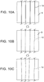
- FIG. 10 explains problems of the conventional molding method of a composite material, which places the optical fiber sensors 10 between the prepreg sheets S and subsequently cures the prepreg sheets S.
- the atmospheric pressure is applied on the optical fiber sensors 10 by vacuuming at the time of curing the prepregs, in addition to own weight of the prepreg sheets S laminated on the optical fiber sensors 10. Accordingly, the optical fiber sensors 10 each having a low rigidity may move from the initial positions as shown in FIG. 10B . Furthermore, when the laminated prepregs are heated and cured, the positions of the optical fiber sensors 10 are further changed by shrinkage due to the curing as shown in FIG. 10C .
- the optical fiber sensors 10 are inserted into the grooves of the cured composite material 30. Therefore, displacement of the optical fiber sensors 10 can be avoided, and the optical fiber sensors 10 can be stably and easily embedded at appropriate positions on a surface of the composite material 30.
- FIG. 11 explains problems in the case of processing grooves, for placing the optical fiber sensors 10, on the composite material 40 after curing.
- fibers 40A of the composite material 40 after curing are not necessarily linear unlike fibers woven into prepregs, as exemplified in FIG. 11 . That is, undulation occurs in the fibers 40A of the composite material 40. This is because displacement of prepregs occurs at the time of laminating prepreg sheets and bagging, and deformation of the prepregs occurs at the time of curing.
- the optical fiber sensors 10 integrated with the composite material 30 are disposed in the grooves formed without cutting processing or press processing of the composite material 30 after curing. Thereby, the fibers of the composite material 30 are neither damaged nor cut for fixing the optical fiber sensors 10 to the composite material 30.
- the length direction of the fibers is the length direction of the optical fiber sensors 10.
- the directions of the fibers of the prepreg sheets S1, each laminated at a position lower than each of the top surfaces of the convex portions 3 of the composite material molding jig 1, are one way, and the longitudinal direction of the convex portions 3 is the length direction of the fibers. Therefore, the fibers of the prepreg sheets S1 are not cut for laying the prepreg sheets S1 in both sides of each convex portion 3. Furthermore, the fibers are not interrupted by each convex portion 3. Thereby, deterioration in strengths of the composite material 30, resulting from cutting or damage of the fibers, can be avoided.
- deterioration in strengths of the composite material 30, resulting from existence of the grooves for fixing the optical fiber sensors 10 is a negligible extent when the number of the prepreg sheet S1 laminated at a position lower than each top surface of the convex portions 3 is made to one sheet by taking advantage of relation that a standard diameter of each optical fiber sensor 10 is approximately same as a standard thickness of one ply of the prepreg sheet S. Therefore, the composite material 30 having necessary strengths can be manufactured easily.
- each of the optical fiber sensors 10 has a low rigidity, the optical fiber sensors 10 are easily broken by an external force. Therefore, embedding the optical fiber sensors 10 in the composite material 30 is most effective in order to prevent breakage of the optical fiber sensors 10. That is, the optical fiber sensors 10 can be safely shielded by being embedded in the composite material 30.
- FIG. 12 shows a configuration of an ultrasonic test system 50 including the optical fiber sensors 10, embedded in the surface of the composite material 30, as elements.
- the ultrasonic test system 50 can be composed of actuators 51, the optical fiber sensors 10, embedded in the surface of the composite material 30, and a signal processing system 52.
- Each of the actuators 51 is an ultrasonic transducer which emits an ultrasonic wave toward a test area of the composite material 30.
- the optical fiber sensors 10 embedded in the surface of the composite material 30 can be manufactured by curing the laminated body 20 of prepregs, which has grooves, to mold the composite material 30, which has the grooves, inserting the optical fiber sensors 10 with an adhesive into the grooves of the composite material 30, and hardening the adhesive.
- the composite material 30 of which the optical fiber sensors 10 have been embedded in the surface can be manufactured by molding the composite material 30 which has grooves each having a depth and a width of cross section corresponding to the thickness of one ply of the prepreg sheet S, and inserting the optical fiber sensors 10, each having a diameter selected according to the thickness of one ply of the prepreg sheet S, into the grooves respectively.
- Each of the optical fiber sensors 10 detects at least one of an ultrasonic wave which has transmitted a test area of an object to be tested made of the composite material 30 and a reflected wave of the ultrasonic wave which has reflected in the test area, to output a detection signal. That is, at least one of an ultrasonic wave which has transmitted a test area and an ultrasonic reflected wave which has reflected in the test area can be used for a flaw detection test of the test area. Therefore, relative positions of the optical fiber sensors 10 and the actuators 51 are determined depending on which of ultrasonic waves which have transmitted the test areas and ultrasonic reflected waves which have reflected in the test areas are to be detected.
- the optical fiber sensors 10 are to be inserted into grooves, which have been formed between uncut fibers of the composite material 30 so that the length direction of the grooves becomes the same direction as the length direction of the fibers before curing.
- the positions and directions of the grooves for inserting the optical fiber sensors 10 are determined so that at least one of ultrasonic waves which have transmitted test areas of the composite material 30 and ultrasonic reflected waves which have reflected in the test areas can be detected by the optical fiber sensors 10 respectively.
- An interval of the optical fiber sensors 10 can be 0.5 m depending on detection sensitivity of ultrasonic waves, for example.
- Typical examples of the optical fiber sensor 10 include a PS-FBG (phase-shifted FBG) sensor besides an FBG sensor.
- An FBG sensor detects an ultrasonic wave by detecting a change of light transmission characteristics or light reflection characteristics of an FBG, which vary by a strain change caused by vibration propagating in the test target, as an optical signal.
- a PS-FBG is an FBG in which a local phase shift has been introduced in a periodic change of a refractive index.
- Especially preferable ultrasonic waves include a Lamb wave from a viewpoint of improving SNR (signal-to-noise ratio) and accuracy of an optical signal which is obtained by each of the optical fiber sensors 10 as an ultrasonic detection signal.
- a Lamb wave propagates in a thin plate of which thickness is not more than half of a wavelength of the ultrasonic wave. Therefore, it is preferable to transmit Lamb waves from the actuators 51.
- the signal processing system 52 has a function to emit ultrasonic waves toward a test area from the actuators 51 by outputting control signals to the actuators 51, and a function to detect a flaw in the test area based on detection signals from the optical fiber sensors 10.
- the signal processing system 52 can be composed of circuitry, including a photoelectric conversion circuit, an A/D (analog-to-digital) converter, and a computer, besides a control circuit which outputs a control signal to each of the actuators 51, at least one light source which outputs laser lights to the optical fiber sensors 10, and optical elements necessary for processing an optical signal, consisting of a reflected light or a transmitted light, which is output from each of the optical fiber sensors 10 as a detection signal of an ultrasonic wave.
- the signal processing system 52 has a function to perform signal processing, such as noise removal processing, averaging processing, envelope detection processing, peak detection processing, and threshold processing, necessary for detecting a flaw.
- a display 53 can be coupled to the signal processing system 52 so that information necessary for a user, such as the existence of a flaw and a position of the flaw, can be displayed.
- At least a part of elements, which process electric signals and digital information, composing the signal processing system 52 can be implemented by circuitry including at least one semiconductor integrated circuit such as at least one processor (e.g., a central processing unit (CPU)), at least one application specific integrated circuit (ASIC), and/or at least one field programmable gate array (FPGA).
- At least one processor can be configured, by reading instructions from at least one machine readable tangible medium, to perform all or a part of functions of the signal processing system 52.
- Such a medium may take many forms, including, but not limited to, any type of magnetic medium such as a hard disk, any type of optical medium such as a CD and a DVD, any type of semiconductor memory (i.e., semiconductor circuit) such as a volatile memory and a non-volatile memory.
- the volatile memory may include a DRAM and a SRAM
- the nonvolatile memory may include a ROM and a NVRAM.
- the ASIC is an integrated circuit (IC) customized to perform
- the FPGA is an integrated circuit designed to be configured after manufacturing in order to perform, all or a part of the functions of the modules shown in Fig. 12 .
- health of the composite material 30 which is used as a material of an aircraft structural object or the like can be monitored using the ultrasonic test system 50 having such a structure. That is, an ultrasonic test of the composite material 30 can be performed using the optical fiber sensors 10 integrated with an object to be tested.
- FIG. 13 shows an example of aircraft structural object 60 including the ultrasonic test system 50, shown in FIG. 12 , as a part.
- the ultrasonic test system 50 can be a part of the aircraft structural object 60, made of the composite material 30.
- the optical fiber sensors 10 can be embedded between the panel 61 and the reinforcement member 62.
- a cross-sectional shape of the reinforcement member 62 is an I shape, a reverse T shape, or the like.
- grooves may be formed on either the panel 61 or the reinforcement member 62 so that the optical fiber sensors 10 can be embedded in the grooves.
- grooves may be formed on both the panel 61 and the reinforcement member 62 so that the optical fiber sensors 10 can be embedded in the grooves.
- a plurality of the optical fiber sensors 10 have been embedded in the panel 61 side so that the longitudinal direction of the reinforcement member 62 becomes the length direction of the optical fiber sensors 10.
- a single optical fiber sensor 10 or a plurality of the optical fiber sensors 10 may be embedded so that a direction perpendicular to the longitudinal direction of the reinforcement member 62 becomes the length direction of the single optical fiber sensor 10 or the plural optical fiber sensors 10.
- each optical fiber sensor 10 may be disposed not only along the panel 61 side, but also along the reinforcement member 62 side.
- the optical fiber sensors 10 may be embedded not only between the panel 61 and the reinforcement member 62, but also between two sheets of the panels 61. That is, the optical fiber sensors 10 can be embedded inside grooves formed in the bonded surface side of at least one of two bonded composite material parts. Therefore, grooves can be formed on at least one of the surfaces to be bonded of the composite material parts, which are objects to be bonded, using the composite material molding jig 1.
- the aircraft structural object 60 where the optical fiber sensors 10 have been embedded between two composite material parts, can be manufactured in various methods.
- the composite material part on which the grooves have been formed is manufactured by heating and curing one of the composite material parts.
- the optical fiber sensors 10 are inserted into the grooves, and fixed with an adhesive.
- a laminated body of prepregs corresponding to the other composite material part is combined with the composite material part, of which the optical fiber sensors 10 have been embedded in the grooves, through an adhesive.
- the aircraft structural object 60 where the optical fiber sensors 10 have been embedded between the two composite material parts can be manufactured by heating and curing the laminated body of prepregs.
- the composite material parts on which the grooves have been formed are manufactured by heating and curing the both composite material parts.
- the composite material parts are combined with each other through an adhesive.
- the optical fiber sensors 10 are inserted into the grooves, and fixed with an adhesive.
- the aircraft structural object 60 where the optical fiber sensors 10 have been embedded between the two composite material parts can be manufactured by hardening the adhesive.
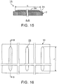
- FIG. 14 is a top view showing a structure of a composite material molding jig according to the second embodiment of the present invention.
- FIG. 15 is a sectional view of the composite material molding jig at the position A-A in FIG. 14 .
- a composite material molding jig 1A in the second embodiment shown in FIG. 14 and FIG. 15 is different from the composite material molding jig 1 in the first embodiment in a point that end portions of convex portions 3A are inside end faces of the rigid portion 2.
- Other structures and functions of the composite material molding jig 1A in the second embodiment are not substantially different from those of the composite material molding jig 1 in the first embodiment. Therefore, the same structures or corresponding structures are shown by the same signs, and their explanations are omitted.
- each of the convex portions 3A of the composite material molding jig 1A can have a length L of not less than 1 m and not more than 10 m in the longitudinal direction of the convex portions 3A, for example. Thereby, regions which should be tested in most aircraft structural objects can be covered.
- the length L of the convex portions 3A in the longitudinal direction is shorter than a distance between the end faces of the rigid portion 2, not through grooves where both ends have not been closed, but blind grooves where both ends or one end has been closed are to be formed on the composite material 30. That is, signal transmission portions of the optical fiber sensors 10 may not be inserted into the grooves of the composite material 30.
- end portions of the grooves can be smoothed so that the optical fiber sensors 10 do not extremely bend at the end portions of the grooves. That is, unevenness can be prevented from being formed at the end portions of the grooves.
- At least one of both end portions of each convex portion 3A in the longitudinal direction can have a shape of which the height and the width of cross section gradually decrease as exemplified in FIG. 14 and FIG. 15 .
- FIG. 16 is a top view showing shapes of grooves 70 of the composite material 30, formed by the convex portions 3A of the composite material molding jig 1A shown in FIG. 14 and FIG. 15 .
- FIG. 17 is a sectional view showing a shape of the groove 70 at the position B-B in FIG. 16 .
- the grooves 70 of the composite material 30 are formed by the convex portions 3A exemplified in FIG. 14 and FIG. 15 , at least one of both end portions of each groove 70 in the length direction can have a shape of which the depth and the width of cross section gradually decrease. That is, the composite material 30 having the grooves 70 of which the depth and the width of each cross section of at least one of both end portions gradually decrease can be molded using the composite material molding jig 1A.
- each optical fiber sensor 10 is to be embedded in the blind groove of which both ends or one end has been closed by three dimensionally smooth curved surfaces or a three dimensionally smooth curved surface.
- the diameter of an optical fiber for transmitting an optical detection signal from the optical fiber sensor 10 is same as that of the optical fiber sensor 10. That is, the diameter of a sensor portion of an optical fiber is same as that of a signal transmission portion of the optical fiber. Accordingly, only the optical fiber sensor 10 portions can be inserted inside the grooves 70, without extremely bending the optical fibers. Thereby, the optical fiber sensors 10 can be prevented from being bent and damaged.
- the end portions of the convex portions 3A also have three dimensionally smooth curved surfaces. Therefore, the prepreg sheets S1 can be disposed along shapes of the convex portions 3A without cutting fibers of prepregs disposed at both sides of each convex portion 3A. Conversely, it is appropriate to determine shapes of the end portions of the convex portions 3A to be smooth enough so that the prepreg sheets S1 can be laid along the convex portions 3A without cutting fibers.
Landscapes
- Engineering & Computer Science (AREA)
- Mechanical Engineering (AREA)
- Chemical & Material Sciences (AREA)
- Physics & Mathematics (AREA)
- Composite Materials (AREA)
- Pathology (AREA)
- Health & Medical Sciences (AREA)
- General Health & Medical Sciences (AREA)
- General Physics & Mathematics (AREA)
- Immunology (AREA)
- Analytical Chemistry (AREA)
- Life Sciences & Earth Sciences (AREA)
- Biochemistry (AREA)
- Acoustics & Sound (AREA)
- Optics & Photonics (AREA)
- Aviation & Aerospace Engineering (AREA)
- Moulding By Coating Moulds (AREA)
- Casting Or Compression Moulding Of Plastics Or The Like (AREA)
- Investigating Or Analyzing Materials By The Use Of Ultrasonic Waves (AREA)
- Length Measuring Devices By Optical Means (AREA)
Applications Claiming Priority (1)
| Application Number | Priority Date | Filing Date | Title |
|---|---|---|---|
| JP2016060990A JP6346214B2 (ja) | 2016-03-24 | 2016-03-24 | 複合材成形治具、複合材成形方法、超音波検査システム、超音波検査方法及び航空機構造体 |
Publications (3)
| Publication Number | Publication Date |
|---|---|
| EP3243640A2 true EP3243640A2 (fr) | 2017-11-15 |
| EP3243640A3 EP3243640A3 (fr) | 2018-01-24 |
| EP3243640B1 EP3243640B1 (fr) | 2021-06-30 |
Family
ID=57995137
Family Applications (1)
| Application Number | Title | Priority Date | Filing Date |
|---|---|---|---|
| EP17155243.3A Active EP3243640B1 (fr) | 2016-03-24 | 2017-02-08 | Procédé de fabrication pour matériau renforcé de fibres |
Country Status (5)
| Country | Link |
|---|---|
| US (1) | US10416121B2 (fr) |
| EP (1) | EP3243640B1 (fr) |
| JP (1) | JP6346214B2 (fr) |
| CN (1) | CN107228901B (fr) |
| ES (1) | ES2883130T3 (fr) |
Families Citing this family (14)
| Publication number | Priority date | Publication date | Assignee | Title |
|---|---|---|---|---|
| GB2529674B (en) * | 2014-08-28 | 2019-07-10 | Silixa Ltd | Flexible Substrate Fiber Optic Sensing Mat For Distributed Acoustic Sensing |
| ES2928656T3 (es) * | 2016-09-26 | 2022-11-21 | Subaru Corp | Sistema de detección de daños y método de detección de daños |
| US10641738B2 (en) * | 2017-07-20 | 2020-05-05 | Airbus (S.A.S.) | Device and method for non-destructive ultrasound inspection of structures made of composite material |
| JP6778221B2 (ja) * | 2018-01-15 | 2020-10-28 | 株式会社Subaru | 締結構造 |
| JP6873073B2 (ja) * | 2018-03-08 | 2021-05-19 | 三菱重工業株式会社 | 評価方法及び評価システム |
| CN109507290B (zh) * | 2018-12-21 | 2022-12-27 | 东华大学 | 微拾音器点阵排列的束纤维断裂点及声测量装置及方法 |
| CN109682884B (zh) * | 2018-12-21 | 2022-12-27 | 东华大学 | 纵列拾音器对称位移的束纤维断裂声测量装置及方法 |
| CN109738516A (zh) * | 2018-12-21 | 2019-05-10 | 东华大学 | 一种横列线阵排列的束纤维断裂声测量装置及方法 |
| JP7161399B2 (ja) * | 2018-12-28 | 2022-10-26 | 株式会社Subaru | 樹脂含浸測定装置 |
| JP7387511B2 (ja) | 2020-03-27 | 2023-11-28 | 株式会社Subaru | 構造健全性診断システム、構造健全性診断方法及び航空機構造体 |
| CN112141315B (zh) * | 2020-09-29 | 2025-03-18 | 中国商用飞机有限责任公司北京民用飞机技术研究中心 | 一种飞机舵面复合材料壁板结构及其成型系统和方法 |
| CN117245942B (zh) * | 2023-11-02 | 2024-04-02 | 哈尔滨远驰航空装备有限公司 | 一种复合材料机载构件、成型模具及成型方法 |
| CN117484909B (zh) * | 2023-11-02 | 2024-04-19 | 哈尔滨远驰航空装备有限公司 | 一种复合材料机载构件、成型方法及其成型模具 |
| KR20250137940A (ko) * | 2024-03-12 | 2025-09-19 | 한국항공대학교산학협력단 | 구조 건전성 모니터링을 위한 복합재 패널 손상 가공 방법 및 이에 이용되는 장치 |
Citations (3)
| Publication number | Priority date | Publication date | Assignee | Title |
|---|---|---|---|---|
| JPH01142262A (ja) | 1987-11-30 | 1989-06-05 | Mitsubishi Heavy Ind Ltd | 電磁式ユニットインジェクタ |
| WO2008123285A1 (fr) | 2007-03-30 | 2008-10-16 | National University Corporation Chiba University | Matériau composite et son procédé de fabrication |
| JP2012020483A (ja) | 2010-07-15 | 2012-02-02 | Ihi Corp | 光ファイバ埋込繊維強化複合材積層板の製造方法及び光ファイバ埋込繊維強化複合材積層板 |
Family Cites Families (18)
| Publication number | Priority date | Publication date | Assignee | Title |
|---|---|---|---|---|
| JPS5424203A (en) | 1977-07-25 | 1979-02-23 | Dai Ichi Seiyaku Co Ltd | Collecting method for noble metals |
| DE3605256C1 (de) * | 1986-02-19 | 1991-03-28 | Dornier Gmbh | Verfahren zur Herstellung von ebenen oder schalenfoermig gekruemmten Bauteilen aus faserverstaerkten Kunststoffen |
| US4869770A (en) * | 1987-12-03 | 1989-09-26 | The Boeing Company | Method and apparatus for laminating composite materials |
| DE4130269C2 (de) * | 1990-09-13 | 1996-05-23 | Toshiba Machine Co Ltd | Verfahren und Vorrichtung zum Herstellen laminierter Prepreg-Teile |
| JPH05164755A (ja) * | 1991-12-16 | 1993-06-29 | Ishikawajima Harima Heavy Ind Co Ltd | 繊維強化複合材積層板の内部欠陥検出方法 |
| US5770155A (en) * | 1995-11-21 | 1998-06-23 | United Technologies Corporation | Composite structure resin cure monitoring apparatus using an optical fiber grating sensor |
| EP0981411A4 (fr) * | 1997-05-06 | 2003-06-25 | Boeing Co | Outil hybride pour le moulage de stratifies |
| JPH11142262A (ja) | 1997-11-06 | 1999-05-28 | Mitsubishi Heavy Ind Ltd | 光ファイバーを埋め込んだ複合材及びその製造方法 |
| DE10214984B4 (de) | 2002-04-04 | 2006-01-19 | Eads Deutschland Gmbh | Aktorik- und Sensoriksystem für Verbundstrukturen |
| JP4251900B2 (ja) * | 2003-03-28 | 2009-04-08 | 藤倉ゴム工業株式会社 | 中空frp成形品の内圧成形方法及び装置 |
| JP2005134189A (ja) * | 2003-10-29 | 2005-05-26 | Hitachi Cable Ltd | 振動検知センシング素子 |
| JP2005288933A (ja) * | 2004-04-01 | 2005-10-20 | Three M Innovative Properties Co | 可とう性成形型及びその製造方法 |
| US20060019088A1 (en) * | 2004-07-20 | 2006-01-26 | Xiaojia Wang | Adhesive layer composition for in-mold decoration |
| JP2012006337A (ja) * | 2010-06-28 | 2012-01-12 | Mitsubishi Heavy Ind Ltd | 繊維強化複合材の製造方法 |
| JP5686994B2 (ja) * | 2010-07-01 | 2015-03-18 | 三菱重工業株式会社 | 成形体の製造方法 |
| KR101443017B1 (ko) | 2011-10-28 | 2014-09-22 | 도레이 카부시키가이샤 | 프리프레그의 제조 방법 |
| CA2815788C (fr) * | 2012-07-31 | 2016-10-11 | The Boeing Company | Stucture composite pourvue d'un systeme de detection integre |
| CN106132673B (zh) * | 2014-03-04 | 2018-03-16 | 庞巴迪公司 | 使用透气聚乙烯真空膜形成复合叠层堆叠的方法和装置 |
-
2016
- 2016-03-24 JP JP2016060990A patent/JP6346214B2/ja active Active
-
2017
- 2017-02-08 EP EP17155243.3A patent/EP3243640B1/fr active Active
- 2017-02-08 ES ES17155243T patent/ES2883130T3/es active Active
- 2017-02-21 CN CN201710095777.4A patent/CN107228901B/zh active Active
- 2017-03-07 US US15/451,792 patent/US10416121B2/en active Active
Patent Citations (3)
| Publication number | Priority date | Publication date | Assignee | Title |
|---|---|---|---|---|
| JPH01142262A (ja) | 1987-11-30 | 1989-06-05 | Mitsubishi Heavy Ind Ltd | 電磁式ユニットインジェクタ |
| WO2008123285A1 (fr) | 2007-03-30 | 2008-10-16 | National University Corporation Chiba University | Matériau composite et son procédé de fabrication |
| JP2012020483A (ja) | 2010-07-15 | 2012-02-02 | Ihi Corp | 光ファイバ埋込繊維強化複合材積層板の製造方法及び光ファイバ埋込繊維強化複合材積層板 |
Also Published As
| Publication number | Publication date |
|---|---|
| JP6346214B2 (ja) | 2018-06-20 |
| JP2017173191A (ja) | 2017-09-28 |
| US20170276648A1 (en) | 2017-09-28 |
| US10416121B2 (en) | 2019-09-17 |
| EP3243640B1 (fr) | 2021-06-30 |
| ES2883130T3 (es) | 2021-12-07 |
| EP3243640A3 (fr) | 2018-01-24 |
| CN107228901B (zh) | 2019-10-29 |
| CN107228901A (zh) | 2017-10-03 |
Similar Documents
| Publication | Publication Date | Title |
|---|---|---|
| EP3243640B1 (fr) | Procédé de fabrication pour matériau renforcé de fibres | |
| US7405391B2 (en) | Modular sensor for damage detection, manufacturing method, and structural composite material | |
| JP5675665B2 (ja) | 光ファイバセンサを備えたハニカムサンドイッチ構造体およびその製造方法 | |
| EP3214439B1 (fr) | Système d'essai par ultrasons utilisant un capteur à fibre optique, procédé d'essai par ultrasons et objet structural d'aéronef | |
| JP6203142B2 (ja) | ハニカムサンドイッチ構造体およびその製造方法 | |
| JP6022059B2 (ja) | ハニカムサンドイッチ構造体およびハニカムサンドイッチ構造体の製造方法 | |
| JP2010519517A (ja) | 光学歪計 | |
| JP6218163B1 (ja) | 光ファイバ温度センサおよびその製造方法 | |
| JP6157186B2 (ja) | 繊維強化複合材料構造体の製造方法 | |
| US20060071668A1 (en) | 3D acoustic imaging using sensor array, longitudinal wave and algebraic reconstruction | |
| JP6873073B2 (ja) | 評価方法及び評価システム | |
| US20050270546A1 (en) | Robotic vision system to locate Z-forms | |
| CN105143853A (zh) | 粘接构造体及粘接状态检测方法 | |
| JP4878013B2 (ja) | 亀裂発生位置の検出方法 | |
| WO2018134597A1 (fr) | Capteur d'indication de cycles de chargement d'une structure | |
| US10345515B2 (en) | Bonded structure, method for manufacturing the same, and bonding state detection method | |
| JP2001004440A (ja) | 光ファイバセンサ埋込板、光ファイバセンサ埋込型複合材料およびその製造方法 | |
| US6970254B2 (en) | Robotic vision system to locate Z-forms | |
| EP2803950A1 (fr) | Capteur réparti | |
| Takahashi et al. | Structural health monitoring of CFRP airframe structures using fiber-optic-based strain mapping | |
| US20170356883A1 (en) | Sensor skin |
Legal Events
| Date | Code | Title | Description |
|---|---|---|---|
| PUAI | Public reference made under article 153(3) epc to a published international application that has entered the european phase |
Free format text: ORIGINAL CODE: 0009012 |
|
| STAA | Information on the status of an ep patent application or granted ep patent |
Free format text: STATUS: THE APPLICATION HAS BEEN PUBLISHED |
|
| AK | Designated contracting states |
Kind code of ref document: A2 Designated state(s): AL AT BE BG CH CY CZ DE DK EE ES FI FR GB GR HR HU IE IS IT LI LT LU LV MC MK MT NL NO PL PT RO RS SE SI SK SM TR |
|
| AX | Request for extension of the european patent |
Extension state: BA ME |
|
| PUAL | Search report despatched |
Free format text: ORIGINAL CODE: 0009013 |
|
| AK | Designated contracting states |
Kind code of ref document: A3 Designated state(s): AL AT BE BG CH CY CZ DE DK EE ES FI FR GB GR HR HU IE IS IT LI LT LU LV MC MK MT NL NO PL PT RO RS SE SI SK SM TR |
|
| AX | Request for extension of the european patent |
Extension state: BA ME |
|
| RIC1 | Information provided on ipc code assigned before grant |
Ipc: B29C 43/02 20060101ALN20171221BHEP Ipc: B29C 70/42 20060101AFI20171221BHEP Ipc: B29C 33/42 20060101ALI20171221BHEP Ipc: B29C 33/00 20060101ALN20171221BHEP Ipc: B29C 70/34 20060101ALI20171221BHEP |
|
| STAA | Information on the status of an ep patent application or granted ep patent |
Free format text: STATUS: REQUEST FOR EXAMINATION WAS MADE |
|
| 17P | Request for examination filed |
Effective date: 20180724 |
|
| RBV | Designated contracting states (corrected) |
Designated state(s): AL AT BE BG CH CY CZ DE DK EE ES FI FR GB GR HR HU IE IS IT LI LT LU LV MC MK MT NL NO PL PT RO RS SE SI SK SM TR |
|
| STAA | Information on the status of an ep patent application or granted ep patent |
Free format text: STATUS: EXAMINATION IS IN PROGRESS |
|
| 17Q | First examination report despatched |
Effective date: 20200402 |
|
| RIC1 | Information provided on ipc code assigned before grant |
Ipc: B29C 33/00 20060101ALN20201120BHEP Ipc: B29C 70/34 20060101ALI20201120BHEP Ipc: B29C 33/42 20060101ALI20201120BHEP Ipc: B29C 70/42 20060101AFI20201120BHEP Ipc: B29C 43/02 20060101ALN20201120BHEP |
|
| RIC1 | Information provided on ipc code assigned before grant |
Ipc: B29C 70/42 20060101AFI20201210BHEP Ipc: B29C 70/34 20060101ALI20201210BHEP Ipc: B29C 33/00 20060101ALN20201210BHEP Ipc: B29C 33/42 20060101ALI20201210BHEP Ipc: B29C 43/58 20060101ALI20201210BHEP Ipc: B29C 43/02 20060101ALN20201210BHEP |
|
| GRAP | Despatch of communication of intention to grant a patent |
Free format text: ORIGINAL CODE: EPIDOSNIGR1 |
|
| STAA | Information on the status of an ep patent application or granted ep patent |
Free format text: STATUS: GRANT OF PATENT IS INTENDED |
|
| RIC1 | Information provided on ipc code assigned before grant |
Ipc: B29C 43/58 20060101ALI20201221BHEP Ipc: B29C 43/02 20060101ALN20201221BHEP Ipc: B29C 33/00 20060101ALN20201221BHEP Ipc: B29C 70/34 20060101ALI20201221BHEP Ipc: B29C 33/42 20060101ALI20201221BHEP Ipc: B29C 70/42 20060101AFI20201221BHEP |
|
| INTG | Intention to grant announced |
Effective date: 20210120 |
|
| GRAS | Grant fee paid |
Free format text: ORIGINAL CODE: EPIDOSNIGR3 |
|
| GRAA | (expected) grant |
Free format text: ORIGINAL CODE: 0009210 |
|
| STAA | Information on the status of an ep patent application or granted ep patent |
Free format text: STATUS: THE PATENT HAS BEEN GRANTED |
|
| AK | Designated contracting states |
Kind code of ref document: B1 Designated state(s): AL AT BE BG CH CY CZ DE DK EE ES FI FR GB GR HR HU IE IS IT LI LT LU LV MC MK MT NL NO PL PT RO RS SE SI SK SM TR |
|
| REG | Reference to a national code |
Ref country code: CH Ref legal event code: EP |
|
| REG | Reference to a national code |
Ref country code: AT Ref legal event code: REF Ref document number: 1405968 Country of ref document: AT Kind code of ref document: T Effective date: 20210715 |
|
| REG | Reference to a national code |
Ref country code: DE Ref legal event code: R096 Ref document number: 602017041079 Country of ref document: DE |
|
| REG | Reference to a national code |
Ref country code: IE Ref legal event code: FG4D |
|
| REG | Reference to a national code |
Ref country code: LT Ref legal event code: MG9D |
|
| PG25 | Lapsed in a contracting state [announced via postgrant information from national office to epo] |
Ref country code: FI Free format text: LAPSE BECAUSE OF FAILURE TO SUBMIT A TRANSLATION OF THE DESCRIPTION OR TO PAY THE FEE WITHIN THE PRESCRIBED TIME-LIMIT Effective date: 20210630 Ref country code: HR Free format text: LAPSE BECAUSE OF FAILURE TO SUBMIT A TRANSLATION OF THE DESCRIPTION OR TO PAY THE FEE WITHIN THE PRESCRIBED TIME-LIMIT Effective date: 20210630 Ref country code: BG Free format text: LAPSE BECAUSE OF FAILURE TO SUBMIT A TRANSLATION OF THE DESCRIPTION OR TO PAY THE FEE WITHIN THE PRESCRIBED TIME-LIMIT Effective date: 20210930 |
|
| REG | Reference to a national code |
Ref country code: NL Ref legal event code: MP Effective date: 20210630 |
|
| REG | Reference to a national code |
Ref country code: AT Ref legal event code: MK05 Ref document number: 1405968 Country of ref document: AT Kind code of ref document: T Effective date: 20210630 |
|
| PG25 | Lapsed in a contracting state [announced via postgrant information from national office to epo] |
Ref country code: LV Free format text: LAPSE BECAUSE OF FAILURE TO SUBMIT A TRANSLATION OF THE DESCRIPTION OR TO PAY THE FEE WITHIN THE PRESCRIBED TIME-LIMIT Effective date: 20210630 Ref country code: GR Free format text: LAPSE BECAUSE OF FAILURE TO SUBMIT A TRANSLATION OF THE DESCRIPTION OR TO PAY THE FEE WITHIN THE PRESCRIBED TIME-LIMIT Effective date: 20211001 Ref country code: NO Free format text: LAPSE BECAUSE OF FAILURE TO SUBMIT A TRANSLATION OF THE DESCRIPTION OR TO PAY THE FEE WITHIN THE PRESCRIBED TIME-LIMIT Effective date: 20210930 Ref country code: RS Free format text: LAPSE BECAUSE OF FAILURE TO SUBMIT A TRANSLATION OF THE DESCRIPTION OR TO PAY THE FEE WITHIN THE PRESCRIBED TIME-LIMIT Effective date: 20210630 Ref country code: SE Free format text: LAPSE BECAUSE OF FAILURE TO SUBMIT A TRANSLATION OF THE DESCRIPTION OR TO PAY THE FEE WITHIN THE PRESCRIBED TIME-LIMIT Effective date: 20210630 |
|
| REG | Reference to a national code |
Ref country code: ES Ref legal event code: FG2A Ref document number: 2883130 Country of ref document: ES Kind code of ref document: T3 Effective date: 20211207 |
|
| PG25 | Lapsed in a contracting state [announced via postgrant information from national office to epo] |
Ref country code: SK Free format text: LAPSE BECAUSE OF FAILURE TO SUBMIT A TRANSLATION OF THE DESCRIPTION OR TO PAY THE FEE WITHIN THE PRESCRIBED TIME-LIMIT Effective date: 20210630 Ref country code: SM Free format text: LAPSE BECAUSE OF FAILURE TO SUBMIT A TRANSLATION OF THE DESCRIPTION OR TO PAY THE FEE WITHIN THE PRESCRIBED TIME-LIMIT Effective date: 20210630 Ref country code: RO Free format text: LAPSE BECAUSE OF FAILURE TO SUBMIT A TRANSLATION OF THE DESCRIPTION OR TO PAY THE FEE WITHIN THE PRESCRIBED TIME-LIMIT Effective date: 20210630 Ref country code: NL Free format text: LAPSE BECAUSE OF FAILURE TO SUBMIT A TRANSLATION OF THE DESCRIPTION OR TO PAY THE FEE WITHIN THE PRESCRIBED TIME-LIMIT Effective date: 20210630 Ref country code: PT Free format text: LAPSE BECAUSE OF FAILURE TO SUBMIT A TRANSLATION OF THE DESCRIPTION OR TO PAY THE FEE WITHIN THE PRESCRIBED TIME-LIMIT Effective date: 20211102 Ref country code: AT Free format text: LAPSE BECAUSE OF FAILURE TO SUBMIT A TRANSLATION OF THE DESCRIPTION OR TO PAY THE FEE WITHIN THE PRESCRIBED TIME-LIMIT Effective date: 20210630 Ref country code: CZ Free format text: LAPSE BECAUSE OF FAILURE TO SUBMIT A TRANSLATION OF THE DESCRIPTION OR TO PAY THE FEE WITHIN THE PRESCRIBED TIME-LIMIT Effective date: 20210630 Ref country code: EE Free format text: LAPSE BECAUSE OF FAILURE TO SUBMIT A TRANSLATION OF THE DESCRIPTION OR TO PAY THE FEE WITHIN THE PRESCRIBED TIME-LIMIT Effective date: 20210630 |
|
| PG25 | Lapsed in a contracting state [announced via postgrant information from national office to epo] |
Ref country code: PL Free format text: LAPSE BECAUSE OF FAILURE TO SUBMIT A TRANSLATION OF THE DESCRIPTION OR TO PAY THE FEE WITHIN THE PRESCRIBED TIME-LIMIT Effective date: 20210630 |
|
| REG | Reference to a national code |
Ref country code: DE Ref legal event code: R097 Ref document number: 602017041079 Country of ref document: DE |
|
| PG25 | Lapsed in a contracting state [announced via postgrant information from national office to epo] |
Ref country code: DK Free format text: LAPSE BECAUSE OF FAILURE TO SUBMIT A TRANSLATION OF THE DESCRIPTION OR TO PAY THE FEE WITHIN THE PRESCRIBED TIME-LIMIT Effective date: 20210630 |
|
| PLBE | No opposition filed within time limit |
Free format text: ORIGINAL CODE: 0009261 |
|
| STAA | Information on the status of an ep patent application or granted ep patent |
Free format text: STATUS: NO OPPOSITION FILED WITHIN TIME LIMIT |
|
| PG25 | Lapsed in a contracting state [announced via postgrant information from national office to epo] |
Ref country code: AL Free format text: LAPSE BECAUSE OF FAILURE TO SUBMIT A TRANSLATION OF THE DESCRIPTION OR TO PAY THE FEE WITHIN THE PRESCRIBED TIME-LIMIT Effective date: 20210630 |
|
| 26N | No opposition filed |
Effective date: 20220331 |
|
| PG25 | Lapsed in a contracting state [announced via postgrant information from national office to epo] |
Ref country code: IT Free format text: LAPSE BECAUSE OF FAILURE TO SUBMIT A TRANSLATION OF THE DESCRIPTION OR TO PAY THE FEE WITHIN THE PRESCRIBED TIME-LIMIT Effective date: 20210630 |
|
| PG25 | Lapsed in a contracting state [announced via postgrant information from national office to epo] |
Ref country code: MC Free format text: LAPSE BECAUSE OF FAILURE TO SUBMIT A TRANSLATION OF THE DESCRIPTION OR TO PAY THE FEE WITHIN THE PRESCRIBED TIME-LIMIT Effective date: 20210630 |
|
| REG | Reference to a national code |
Ref country code: CH Ref legal event code: PL |
|
| REG | Reference to a national code |
Ref country code: BE Ref legal event code: MM Effective date: 20220228 |
|
| PG25 | Lapsed in a contracting state [announced via postgrant information from national office to epo] |
Ref country code: LU Free format text: LAPSE BECAUSE OF NON-PAYMENT OF DUE FEES Effective date: 20220208 |
|
| PG25 | Lapsed in a contracting state [announced via postgrant information from national office to epo] |
Ref country code: LI Free format text: LAPSE BECAUSE OF NON-PAYMENT OF DUE FEES Effective date: 20220228 Ref country code: IE Free format text: LAPSE BECAUSE OF NON-PAYMENT OF DUE FEES Effective date: 20220208 Ref country code: CH Free format text: LAPSE BECAUSE OF NON-PAYMENT OF DUE FEES Effective date: 20220228 |
|
| PG25 | Lapsed in a contracting state [announced via postgrant information from national office to epo] |
Ref country code: BE Free format text: LAPSE BECAUSE OF NON-PAYMENT OF DUE FEES Effective date: 20220228 |
|
| PG25 | Lapsed in a contracting state [announced via postgrant information from national office to epo] |
Ref country code: LT Free format text: LAPSE BECAUSE OF FAILURE TO SUBMIT A TRANSLATION OF THE DESCRIPTION OR TO PAY THE FEE WITHIN THE PRESCRIBED TIME-LIMIT Effective date: 20210630 |
|
| PG25 | Lapsed in a contracting state [announced via postgrant information from national office to epo] |
Ref country code: HU Free format text: LAPSE BECAUSE OF FAILURE TO SUBMIT A TRANSLATION OF THE DESCRIPTION OR TO PAY THE FEE WITHIN THE PRESCRIBED TIME-LIMIT; INVALID AB INITIO Effective date: 20170208 |
|
| PG25 | Lapsed in a contracting state [announced via postgrant information from national office to epo] |
Ref country code: MK Free format text: LAPSE BECAUSE OF FAILURE TO SUBMIT A TRANSLATION OF THE DESCRIPTION OR TO PAY THE FEE WITHIN THE PRESCRIBED TIME-LIMIT Effective date: 20210630 Ref country code: CY Free format text: LAPSE BECAUSE OF FAILURE TO SUBMIT A TRANSLATION OF THE DESCRIPTION OR TO PAY THE FEE WITHIN THE PRESCRIBED TIME-LIMIT Effective date: 20210630 |
|
| PG25 | Lapsed in a contracting state [announced via postgrant information from national office to epo] |
Ref country code: TR Free format text: LAPSE BECAUSE OF FAILURE TO SUBMIT A TRANSLATION OF THE DESCRIPTION OR TO PAY THE FEE WITHIN THE PRESCRIBED TIME-LIMIT Effective date: 20210630 |
|
| PG25 | Lapsed in a contracting state [announced via postgrant information from national office to epo] |
Ref country code: MT Free format text: LAPSE BECAUSE OF FAILURE TO SUBMIT A TRANSLATION OF THE DESCRIPTION OR TO PAY THE FEE WITHIN THE PRESCRIBED TIME-LIMIT Effective date: 20210630 |
|
| PGFP | Annual fee paid to national office [announced via postgrant information from national office to epo] |
Ref country code: ES Payment date: 20250331 Year of fee payment: 9 |
|
| PGFP | Annual fee paid to national office [announced via postgrant information from national office to epo] |
Ref country code: GB Payment date: 20260219 Year of fee payment: 10 |
|
| PGFP | Annual fee paid to national office [announced via postgrant information from national office to epo] |
Ref country code: DE Payment date: 20260218 Year of fee payment: 10 |
|
| PGFP | Annual fee paid to national office [announced via postgrant information from national office to epo] |
Ref country code: FR Payment date: 20260218 Year of fee payment: 10 |