EP3243678B1 - Nutzfahrzeugaufbau - Google Patents
Nutzfahrzeugaufbau Download PDFInfo
- Publication number
- EP3243678B1 EP3243678B1 EP17000801.5A EP17000801A EP3243678B1 EP 3243678 B1 EP3243678 B1 EP 3243678B1 EP 17000801 A EP17000801 A EP 17000801A EP 3243678 B1 EP3243678 B1 EP 3243678B1
- Authority
- EP
- European Patent Office
- Prior art keywords
- load securing
- vehicle body
- commercial vehicle
- securing element
- external beam
- Prior art date
- Legal status (The legal status is an assumption and is not a legal conclusion. Google has not performed a legal analysis and makes no representation as to the accuracy of the status listed.)
- Active
Links
Images

Classifications
-
- B—PERFORMING OPERATIONS; TRANSPORTING
- B60—VEHICLES IN GENERAL
- B60J—WINDOWS, WINDSCREENS, NON-FIXED ROOFS, DOORS, OR SIMILAR DEVICES FOR VEHICLES; REMOVABLE EXTERNAL PROTECTIVE COVERINGS SPECIALLY ADAPTED FOR VEHICLES
- B60J5/00—Doors
- B60J5/04—Doors arranged at the vehicle sides
- B60J5/06—Doors arranged at the vehicle sides slidable; foldable
- B60J5/062—Doors arranged at the vehicle sides slidable; foldable for utility vehicles or public transport
- B60J5/065—Doors arranged at the vehicle sides slidable; foldable for utility vehicles or public transport with non-rigid elements, e.g. side curtains
-
- B—PERFORMING OPERATIONS; TRANSPORTING
- B60—VEHICLES IN GENERAL
- B60J—WINDOWS, WINDSCREENS, NON-FIXED ROOFS, DOORS, OR SIMILAR DEVICES FOR VEHICLES; REMOVABLE EXTERNAL PROTECTIVE COVERINGS SPECIALLY ADAPTED FOR VEHICLES
- B60J7/00—Non-fixed roofs; Roofs with movable panels, e.g. rotary sunroofs
- B60J7/08—Non-fixed roofs; Roofs with movable panels, e.g. rotary sunroofs of non-sliding type, i.e. movable or removable roofs or panels, e.g. let-down tops or roofs capable of being easily detached or of assuming a collapsed or inoperative position
- B60J7/16—Non-fixed roofs; Roofs with movable panels, e.g. rotary sunroofs of non-sliding type, i.e. movable or removable roofs or panels, e.g. let-down tops or roofs capable of being easily detached or of assuming a collapsed or inoperative position non-foldable and rigid, e.g. a one-piece hard-top or a single rigid roof panel
- B60J7/1607—Non-fixed roofs; Roofs with movable panels, e.g. rotary sunroofs of non-sliding type, i.e. movable or removable roofs or panels, e.g. let-down tops or roofs capable of being easily detached or of assuming a collapsed or inoperative position non-foldable and rigid, e.g. a one-piece hard-top or a single rigid roof panel for covering load areas, e.g. rigid panels for pick-up truck beds
- B60J7/1614—Non-fixed roofs; Roofs with movable panels, e.g. rotary sunroofs of non-sliding type, i.e. movable or removable roofs or panels, e.g. let-down tops or roofs capable of being easily detached or of assuming a collapsed or inoperative position non-foldable and rigid, e.g. a one-piece hard-top or a single rigid roof panel for covering load areas, e.g. rigid panels for pick-up truck beds with a vertical lifting movement maintaining the inclination of the roof or panel
-
- B—PERFORMING OPERATIONS; TRANSPORTING
- B60—VEHICLES IN GENERAL
- B60P—VEHICLES ADAPTED FOR LOAD TRANSPORTATION OR TO TRANSPORT, TO CARRY, OR TO COMPRISE SPECIAL LOADS OR OBJECTS
- B60P7/00—Securing or covering of load on vehicles
- B60P7/06—Securing of load
- B60P7/08—Securing to the vehicle floor or sides
- B60P7/0876—Securing to the vehicle floor or sides using restraining net or tarpaulin in contact with the load
Definitions
- the invention relates to a commercial vehicle structure according to the preamble of claim 1.
- the loading space floor must be constructed in a structurally complex manner with corresponding fastening rails which are to be let into the loading space floor at a distance from one another. This is also time-consuming.
- a utility vehicle structure with a displaceable load securing device in which the load securing device for attaching a securing means extends on an outer boom.
- a slide for moving the load securing device along the spar is held on the outer boom.
- the load securing element cannot be determined in a certain operating position.
- the utility vehicle structure of the type mentioned is characterized in that the load securing element can be fixed to the fastening receptacle of the outer boom via a locking element, the locking element being designed as a clamping brake.
- the load securing element of this load securing arrangement extends in a simple manner from the fastening rail to the upper outer tree, which only needs to be structurally expanded so that it in turn has a corresponding fastening receptacle for this load securing element.
- this load securing element can be designed, for example, as a tensioning belt with a corresponding hook-shaped connecting element in order to be inserted into corresponding receptacles in the fastening rail on the cargo space floor.
- This fastening rail can, as in a conventional manner, be designed as a metallic strip which laterally delimits the cargo space and which has many fastening openings which are arranged at a distance from one another and into which a fastening hook is to be introduced.
- the load securing element in turn as a vertical connection can, for. B. be designed as a belt but also as a profile, for example from a metallic or non-metallic material or from a glass or carbon fiber reinforced plastic, be it as a rectangular profile or z. B.
- connection of the load securing element only needs to be designed in such a way that, in the event of securing, a non-positive and / or positive connection of the load securing element to the commercial vehicle body is established. Therefore, assembly is also possible with a certain amount of play in the load securing element itself and / or in the connection technology.
- connection technology A multitude of possible solutions from connection technology are known to those skilled in the art.
- the load securing element can be fixed on a fastening receptacle of the outer boom via a locking element.
- This locking element is designed as a clamping brake, which can be locked in the device position with little technical effort.
- the locking element can also have a locking or latching element that engages in a predetermined locking or detent.
- the latch receptacles or the latching can extend in the longitudinal direction of the outer boom over a shorter or longer section, so that the load securing element can be locked in different positions, which results in a high degree of variability of the system.
- This load securing element can be tensioned to the fastening rail by a second tensioning element, for example a tensioning belt. Additional tensioning elements are particularly advantageous when the load securing element is not connected to the outer boom in a force-fitting and / or form-fitting manner. The tensioning elements can then additionally absorb the load securing forces in and / or against the direction of travel.
- the tensioning elements can be connected to the fastening rail in the lower area of the vehicle body, the outer tree arranged in the upper area of the vehicle body, a lockable central stanchion and / or the roof structure.
- the fastening receptacle in the outer tree is designed as a guide device.
- a running chamber or a running rail can serve as a guide device.
- several guide devices can be provided, which are present in sections or also continuously.
- a carriage with z. B. one or two rollers or a rollerless sliding element can for example be moved along the entire longitudinal extent of the guide element so that the load securing element can be placed anywhere on the outer boom. If the load securing element is then connected to the fastening receptacle of the fastening rail, the load securing element can be braced, for example via the outer tree, via the tensioning element.
- the tensioning element preferably extends in a diagonal orientation to a fastening receptacle of the fastening rail, which is at a certain distance from the fastening receptacle into which the load securing element is hooked.
- the middle stanchion as a load securing element, it can be connected to the commercial vehicle body in a form-fitting and / or force-fitting manner via a lock.
- the tensioning element can be designed in any way so that it is able to absorb load securing forces. For this purpose, it can be designed as a tension belt, tension cable or tension chain. However, the load securing forces are also able to accommodate dimensionally stable spatial bodies that are used as a tensioning element.
- a tension rod for example, can be used as a tensioning element as a rigid spatial body.
- the tensionable tensioning element can be mounted without play, for example, using a tensioning device such as a ratchet. Rigid clamping elements can also be connected to the utility vehicle structure via other fastening means.
- the carriage is preferably designed in such a way that it also has a braking device. This can be designed in such a way that it becomes effective, namely automatically, when the load-securing element is tensioned via the tensioning element or via the load-securing element itself.
- the load securing element in turn has recordings, for. B. eyelets, keyhole recesses and the like holding devices or fastening receptacles in order to provide further load securing elements transversely to the longitudinal extent of the cargo space floor. It is preferred that such an additional load securing element extending transversely to the loading space floor is designed as a support element.
- This can, for example, be a support element in the form of a Grid made of tension belts, which are to be attached to the corresponding holders or receptacles on two oppositely arranged load securing elements. It is also possible to introduce dimensionally stable cross connections such as, for example, metallic cross bars.
- FIG. 1 a section of a utility vehicle structure 1 is shown, which has a loading space floor 2, to which a lateral fastening rail 3 adjoins, which has various holes 4 as fastening receptacles.
- the utility vehicle superstructure has an outer tree 5 in the upper lateral corner area. Side walls can extend between the loading space floor 2 and the outer tree 5, but also lateral sliding tarpaulins and similar parts that delimit a loading space.
- a roof can adjoin the outer tree 5, which can also be designed, for example, as a sliding tarpaulin roof.
- the outer tree 5 in turn has a continuous fastening receptacle 6, which is designed as a barrel chamber in the embodiment shown.
- a carriage 7 with two rollers 8 can run and thus be moved.
- This carriage has a fastening eyelet 9 to which a load securing element 10 in the form of a belt is fastened.
- This belt is thus slidably attached to the outer boom 5 as a load securing element 10.
- a hook 11 is provided which is hooked into a fastening receptacle 4 of the fastening rail.
- a tensioning element 12 is also provided, which in the exemplary embodiment is also designed as a tensioning belt and at its end facing the fastening rail 3 also has a fastening hook 11 that is also hooked into a fastening receptacle 4 of the fastening rail 3 .
- the load securing element 10 in turn has eyelets 13 as fastening elements for load support elements 14 and 15 which extend transversely above the loading floor 2 and which are connected by hooks 16. These load support elements 14 and 15 form a grid which extends across the loading floor 2.
- the load securing element 10 with the load support elements 14 and 15 and the tensioning element 12 can be attached to almost any Any point on the loading floor can be provided in order to support the load in the longitudinal direction of the commercial vehicle body.
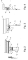
- a braking device 17 for the carriage 7 is shown here again.
- the exemplary embodiment according to FIG Fig. 4 the braking device 17 is designed in such a way that when the load securing element 10 is braced, a head 17.1 is pressed into a recess so that the carriage 7 is thereby secured against movement.
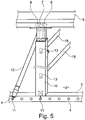
- the load securing element 10 in the embodiment according to Fig. 5 designed as a metallic rectangular profile.
- This metallic rectangular profile has keyhole holes as fastening receptacles 13, into which, in this case, metallic cross struts 18 are introduced as support elements which extend across the loading floor 2.
Landscapes
- Engineering & Computer Science (AREA)
- Mechanical Engineering (AREA)
- Transportation (AREA)
- Fittings On The Vehicle Exterior For Carrying Loads, And Devices For Holding Or Mounting Articles (AREA)
Priority Applications (1)
| Application Number | Priority Date | Filing Date | Title |
|---|---|---|---|
| PL17000801T PL3243678T3 (pl) | 2016-05-12 | 2017-05-10 | Nadwozie pojazdu użytkowego |
Applications Claiming Priority (1)
| Application Number | Priority Date | Filing Date | Title |
|---|---|---|---|
| DE102016108827.7A DE102016108827B4 (de) | 2016-05-12 | 2016-05-12 | Nutzfahrzeugaufbau |
Publications (2)
| Publication Number | Publication Date |
|---|---|
| EP3243678A1 EP3243678A1 (de) | 2017-11-15 |
| EP3243678B1 true EP3243678B1 (de) | 2021-04-07 |
Family
ID=58701361
Family Applications (1)
| Application Number | Title | Priority Date | Filing Date |
|---|---|---|---|
| EP17000801.5A Active EP3243678B1 (de) | 2016-05-12 | 2017-05-10 | Nutzfahrzeugaufbau |
Country Status (5)
| Country | Link |
|---|---|
| EP (1) | EP3243678B1 (da) |
| DE (1) | DE102016108827B4 (da) |
| DK (1) | DK3243678T3 (da) |
| ES (1) | ES2877202T3 (da) |
| PL (1) | PL3243678T3 (da) |
Families Citing this family (2)
| Publication number | Priority date | Publication date | Assignee | Title |
|---|---|---|---|---|
| DE202018103592U1 (de) * | 2018-06-25 | 2018-07-09 | Westdeutscher Drahtseil-Verkauf Dolezych Gmbh & Co. Kg | Flächiges Sicherungsmittel |
| DE102020001719B3 (de) | 2020-03-16 | 2021-08-12 | Thorald Keim | Plane mit Hebelspannern und Distanzstücken zu einem planenfernen Rahmenbereich |
Family Cites Families (11)
| Publication number | Priority date | Publication date | Assignee | Title |
|---|---|---|---|---|
| US3095830A (en) | 1960-07-06 | 1963-07-02 | Acf Ind Inc | Lading bracing arrangement |
| US4439076A (en) | 1981-04-01 | 1984-03-27 | Unarco Industries, Inc. | Movable freight restraining device for freight cars and the like |
| US4826236A (en) | 1987-05-14 | 1989-05-02 | Utility Trailer Manufacturing Co. | Curtain-sided vehicle apparatus |
| US4795208A (en) * | 1987-08-19 | 1989-01-03 | Morgan Corporation | Net restraint system |
| AU596870B2 (en) * | 1987-10-07 | 1990-05-17 | Krueger Transport Equipment Pty Ltd | Curtain sided trailers |
| GB2327450A (en) * | 1997-02-11 | 1999-01-27 | Structure Flex Limited | Improvements in tensioning systems for container body covers |
| US7367765B2 (en) * | 2004-09-30 | 2008-05-06 | Holland, L.P. | Lading tie snugger system for securing cargo |
| DE202008008651U1 (de) | 2008-06-27 | 2009-11-19 | Kögel Fahrzeugwerke GmbH | Nutzfahrzeug-Aufbau und Halteelement für einen Nutzfahrzeug-Aufbau |
| PL2835282T3 (pl) | 2013-08-05 | 2019-10-31 | Schmitz Cargobull Ag | Nadbudowa pojazdu użytkowego z przesuwnym urządzeniem zabezpieczającym ładunek |
| DE102014104428A1 (de) * | 2014-03-28 | 2015-10-01 | CIMC Silvergreen GmbH | Fahrzeugaufbau |
| DE102015108782B4 (de) | 2015-06-03 | 2020-10-08 | Kögel Trailer GmbH | Fahrzeugaufbau, insbesondere für Nutzfahrzeuge, Nutzfahrzeug mit einem solchen Fahrzeugaufbau und Herstellungsverfahren |
-
2016
- 2016-05-12 DE DE102016108827.7A patent/DE102016108827B4/de active Active
-
2017
- 2017-05-10 EP EP17000801.5A patent/EP3243678B1/de active Active
- 2017-05-10 PL PL17000801T patent/PL3243678T3/pl unknown
- 2017-05-10 ES ES17000801T patent/ES2877202T3/es active Active
- 2017-05-10 DK DK17000801.5T patent/DK3243678T3/da active
Non-Patent Citations (1)
| Title |
|---|
| None * |
Also Published As
| Publication number | Publication date |
|---|---|
| ES2877202T3 (es) | 2021-11-16 |
| DE102016108827A1 (de) | 2017-11-16 |
| EP3243678A1 (de) | 2017-11-15 |
| DK3243678T3 (da) | 2021-06-28 |
| DE102016108827B4 (de) | 2026-02-26 |
| PL3243678T3 (pl) | 2021-12-20 |
Similar Documents
| Publication | Publication Date | Title |
|---|---|---|
| EP2835282B1 (de) | Nutzfahrzeugaufbau mit verschiebbarer Ladungssicherungseinrichtung | |
| EP1481844A1 (de) | Zurrpunktvorrichtung für ein Frachtladesystem eines Transportmittels, insbesondere eines Flugzeuges | |
| EP3235681A1 (de) | Nutzfahrzeugaufbau mit ladungssicherung für insbesondere coils | |
| DE102007032235A1 (de) | Leichtes Schienensystem zur Krafteinleitung großer Lasten in eine Struktur | |
| DE102008011704B4 (de) | Anordnung und Verfahren zur Ladungssicherung sowie Nutzfahrzeug mit einer derartigen Anordnung | |
| EP3243678B1 (de) | Nutzfahrzeugaufbau | |
| EP2687404B1 (de) | Anordnung zur Ladungssicherung | |
| DE102016207657B4 (de) | Anordnung zur Befestigung von Ladegütern auf einer Ladefläche eines Kraftfahrzeugs | |
| DE102006023672A1 (de) | Aufbau für die Ladefläche eines Transportfahrzeugs | |
| EP4306361A2 (de) | Zurreinrichtung zur teilladungssicherung in fahrtrichtung eines nutzfahrzeugaufbaus, ladungssicherungssystem und nutzfahrzeugaufbau mit einer solchen zurreinrichtung | |
| DE102018005276B4 (de) | Nutzfahrzeugaufbau | |
| DE10250463A1 (de) | Vorrichtung zur Sicherung von Ladung | |
| DE102015112843A1 (de) | Runge für einen Nutzfahrzeugaufbau sowie Ladungssicherungssystem, Nutzfahrzeugaufbau und Nutzfahrzeug mit einer solchen Runge | |
| EP3243700B1 (de) | Nutzfahrzeugaufbau | |
| EP3069929B1 (de) | Verwendung eines Lochs in einem Querträger | |
| EP3666567B1 (de) | Begrenzungsplane für einen nutzfahrzeugaufbau, nutzfahrzeugaufbau und nutzfahrzeug mit einem nutzfahrzeugaufbau | |
| EP3623219B1 (de) | Profil zur ladungssicherung sowie ladefläche zur aufnahme eines transportguts | |
| DE102016115786B4 (de) | Ladungssicherungseinrichtung für Nutzfahrzeuge | |
| EP3683076A1 (de) | Nutzfahrzeugaufbau und nutzfahrzeug mit einem derartigen nutzfahrzeugaufbau | |
| DE102011117441A1 (de) | Vorrichtung zur Halterung von wenigstens einem Transportsicherungsnetz, in einem Fahrzeug | |
| DE10162164B4 (de) | Ladevorrichtung | |
| EP3543052B1 (de) | Nutzfahrzeugaufbau und nutzfahrzeug | |
| DE29708615U1 (de) | Vorrichtung zur Befestigung von Gegenständen mit einem im wesentlichen rechteckigen Querschnitt in Lastkraftwagen und/oder Anhängern | |
| DE102017120200B4 (de) | Traggerüst für einen Planenaufbau eines Nutzfahrzeugs | |
| EP4488117A1 (de) | Nutzfahrzeugaufbau mit ladungssicherungseinrichtung und verfahren zur ladungssicherung |
Legal Events
| Date | Code | Title | Description |
|---|---|---|---|
| PUAI | Public reference made under article 153(3) epc to a published international application that has entered the european phase |
Free format text: ORIGINAL CODE: 0009012 |
|
| STAA | Information on the status of an ep patent application or granted ep patent |
Free format text: STATUS: THE APPLICATION HAS BEEN PUBLISHED |
|
| AK | Designated contracting states |
Kind code of ref document: A1 Designated state(s): AL AT BE BG CH CY CZ DE DK EE ES FI FR GB GR HR HU IE IS IT LI LT LU LV MC MK MT NL NO PL PT RO RS SE SI SK SM TR |
|
| AX | Request for extension of the european patent |
Extension state: BA ME |
|
| STAA | Information on the status of an ep patent application or granted ep patent |
Free format text: STATUS: REQUEST FOR EXAMINATION WAS MADE |
|
| 17P | Request for examination filed |
Effective date: 20171222 |
|
| RBV | Designated contracting states (corrected) |
Designated state(s): AL AT BE BG CH CY CZ DE DK EE ES FI FR GB GR HR HU IE IS IT LI LT LU LV MC MK MT NL NO PL PT RO RS SE SI SK SM TR |
|
| STAA | Information on the status of an ep patent application or granted ep patent |
Free format text: STATUS: EXAMINATION IS IN PROGRESS |
|
| 17Q | First examination report despatched |
Effective date: 20200227 |
|
| GRAP | Despatch of communication of intention to grant a patent |
Free format text: ORIGINAL CODE: EPIDOSNIGR1 |
|
| STAA | Information on the status of an ep patent application or granted ep patent |
Free format text: STATUS: GRANT OF PATENT IS INTENDED |
|
| INTG | Intention to grant announced |
Effective date: 20201030 |
|
| GRAS | Grant fee paid |
Free format text: ORIGINAL CODE: EPIDOSNIGR3 |
|
| GRAA | (expected) grant |
Free format text: ORIGINAL CODE: 0009210 |
|
| STAA | Information on the status of an ep patent application or granted ep patent |
Free format text: STATUS: THE PATENT HAS BEEN GRANTED |
|
| AK | Designated contracting states |
Kind code of ref document: B1 Designated state(s): AL AT BE BG CH CY CZ DE DK EE ES FI FR GB GR HR HU IE IS IT LI LT LU LV MC MK MT NL NO PL PT RO RS SE SI SK SM TR |
|
| REG | Reference to a national code |
Ref country code: GB Ref legal event code: FG4D Free format text: NOT ENGLISH |
|
| REG | Reference to a national code |
Ref country code: CH Ref legal event code: EP Ref country code: AT Ref legal event code: REF Ref document number: 1379236 Country of ref document: AT Kind code of ref document: T Effective date: 20210415 |
|
| REG | Reference to a national code |
Ref country code: DE Ref legal event code: R096 Ref document number: 502017009941 Country of ref document: DE |
|
| REG | Reference to a national code |
Ref country code: IE Ref legal event code: FG4D Free format text: LANGUAGE OF EP DOCUMENT: GERMAN |
|
| REG | Reference to a national code |
Ref country code: NL Ref legal event code: FP |
|
| REG | Reference to a national code |
Ref country code: DK Ref legal event code: T3 Effective date: 20210623 |
|
| REG | Reference to a national code |
Ref country code: SE Ref legal event code: TRGR |
|
| REG | Reference to a national code |
Ref country code: LT Ref legal event code: MG9D |
|
| PG25 | Lapsed in a contracting state [announced via postgrant information from national office to epo] |
Ref country code: LT Free format text: LAPSE BECAUSE OF FAILURE TO SUBMIT A TRANSLATION OF THE DESCRIPTION OR TO PAY THE FEE WITHIN THE PRESCRIBED TIME-LIMIT Effective date: 20210407 Ref country code: FI Free format text: LAPSE BECAUSE OF FAILURE TO SUBMIT A TRANSLATION OF THE DESCRIPTION OR TO PAY THE FEE WITHIN THE PRESCRIBED TIME-LIMIT Effective date: 20210407 Ref country code: BG Free format text: LAPSE BECAUSE OF FAILURE TO SUBMIT A TRANSLATION OF THE DESCRIPTION OR TO PAY THE FEE WITHIN THE PRESCRIBED TIME-LIMIT Effective date: 20210707 Ref country code: HR Free format text: LAPSE BECAUSE OF FAILURE TO SUBMIT A TRANSLATION OF THE DESCRIPTION OR TO PAY THE FEE WITHIN THE PRESCRIBED TIME-LIMIT Effective date: 20210407 |
|
| REG | Reference to a national code |
Ref country code: ES Ref legal event code: FG2A Ref document number: 2877202 Country of ref document: ES Kind code of ref document: T3 Effective date: 20211116 |
|
| PG25 | Lapsed in a contracting state [announced via postgrant information from national office to epo] |
Ref country code: RS Free format text: LAPSE BECAUSE OF FAILURE TO SUBMIT A TRANSLATION OF THE DESCRIPTION OR TO PAY THE FEE WITHIN THE PRESCRIBED TIME-LIMIT Effective date: 20210407 Ref country code: PT Free format text: LAPSE BECAUSE OF FAILURE TO SUBMIT A TRANSLATION OF THE DESCRIPTION OR TO PAY THE FEE WITHIN THE PRESCRIBED TIME-LIMIT Effective date: 20210809 Ref country code: NO Free format text: LAPSE BECAUSE OF FAILURE TO SUBMIT A TRANSLATION OF THE DESCRIPTION OR TO PAY THE FEE WITHIN THE PRESCRIBED TIME-LIMIT Effective date: 20210707 Ref country code: IS Free format text: LAPSE BECAUSE OF FAILURE TO SUBMIT A TRANSLATION OF THE DESCRIPTION OR TO PAY THE FEE WITHIN THE PRESCRIBED TIME-LIMIT Effective date: 20210807 Ref country code: LV Free format text: LAPSE BECAUSE OF FAILURE TO SUBMIT A TRANSLATION OF THE DESCRIPTION OR TO PAY THE FEE WITHIN THE PRESCRIBED TIME-LIMIT Effective date: 20210407 Ref country code: GR Free format text: LAPSE BECAUSE OF FAILURE TO SUBMIT A TRANSLATION OF THE DESCRIPTION OR TO PAY THE FEE WITHIN THE PRESCRIBED TIME-LIMIT Effective date: 20210708 |
|
| REG | Reference to a national code |
Ref country code: CH Ref legal event code: PL |
|
| REG | Reference to a national code |
Ref country code: DE Ref legal event code: R097 Ref document number: 502017009941 Country of ref document: DE |
|
| PG25 | Lapsed in a contracting state [announced via postgrant information from national office to epo] |
Ref country code: MC Free format text: LAPSE BECAUSE OF FAILURE TO SUBMIT A TRANSLATION OF THE DESCRIPTION OR TO PAY THE FEE WITHIN THE PRESCRIBED TIME-LIMIT Effective date: 20210407 Ref country code: LU Free format text: LAPSE BECAUSE OF NON-PAYMENT OF DUE FEES Effective date: 20210510 Ref country code: LI Free format text: LAPSE BECAUSE OF NON-PAYMENT OF DUE FEES Effective date: 20210531 Ref country code: CH Free format text: LAPSE BECAUSE OF NON-PAYMENT OF DUE FEES Effective date: 20210531 Ref country code: CZ Free format text: LAPSE BECAUSE OF FAILURE TO SUBMIT A TRANSLATION OF THE DESCRIPTION OR TO PAY THE FEE WITHIN THE PRESCRIBED TIME-LIMIT Effective date: 20210407 Ref country code: EE Free format text: LAPSE BECAUSE OF FAILURE TO SUBMIT A TRANSLATION OF THE DESCRIPTION OR TO PAY THE FEE WITHIN THE PRESCRIBED TIME-LIMIT Effective date: 20210407 Ref country code: RO Free format text: LAPSE BECAUSE OF FAILURE TO SUBMIT A TRANSLATION OF THE DESCRIPTION OR TO PAY THE FEE WITHIN THE PRESCRIBED TIME-LIMIT Effective date: 20210407 Ref country code: SK Free format text: LAPSE BECAUSE OF FAILURE TO SUBMIT A TRANSLATION OF THE DESCRIPTION OR TO PAY THE FEE WITHIN THE PRESCRIBED TIME-LIMIT Effective date: 20210407 Ref country code: SM Free format text: LAPSE BECAUSE OF FAILURE TO SUBMIT A TRANSLATION OF THE DESCRIPTION OR TO PAY THE FEE WITHIN THE PRESCRIBED TIME-LIMIT Effective date: 20210407 |
|
| PLBE | No opposition filed within time limit |
Free format text: ORIGINAL CODE: 0009261 |
|
| STAA | Information on the status of an ep patent application or granted ep patent |
Free format text: STATUS: NO OPPOSITION FILED WITHIN TIME LIMIT |
|
| 26N | No opposition filed |
Effective date: 20220110 |
|
| PG25 | Lapsed in a contracting state [announced via postgrant information from national office to epo] |
Ref country code: IE Free format text: LAPSE BECAUSE OF NON-PAYMENT OF DUE FEES Effective date: 20210510 |
|
| PG25 | Lapsed in a contracting state [announced via postgrant information from national office to epo] |
Ref country code: IS Free format text: LAPSE BECAUSE OF FAILURE TO SUBMIT A TRANSLATION OF THE DESCRIPTION OR TO PAY THE FEE WITHIN THE PRESCRIBED TIME-LIMIT Effective date: 20210807 Ref country code: AL Free format text: LAPSE BECAUSE OF FAILURE TO SUBMIT A TRANSLATION OF THE DESCRIPTION OR TO PAY THE FEE WITHIN THE PRESCRIBED TIME-LIMIT Effective date: 20210407 |
|
| PG25 | Lapsed in a contracting state [announced via postgrant information from national office to epo] |
Ref country code: HU Free format text: LAPSE BECAUSE OF FAILURE TO SUBMIT A TRANSLATION OF THE DESCRIPTION OR TO PAY THE FEE WITHIN THE PRESCRIBED TIME-LIMIT; INVALID AB INITIO Effective date: 20170510 |
|
| P01 | Opt-out of the competence of the unified patent court (upc) registered |
Effective date: 20230518 |
|
| PG25 | Lapsed in a contracting state [announced via postgrant information from national office to epo] |
Ref country code: CY Free format text: LAPSE BECAUSE OF FAILURE TO SUBMIT A TRANSLATION OF THE DESCRIPTION OR TO PAY THE FEE WITHIN THE PRESCRIBED TIME-LIMIT Effective date: 20210407 |
|
| PG25 | Lapsed in a contracting state [announced via postgrant information from national office to epo] |
Ref country code: MK Free format text: LAPSE BECAUSE OF FAILURE TO SUBMIT A TRANSLATION OF THE DESCRIPTION OR TO PAY THE FEE WITHIN THE PRESCRIBED TIME-LIMIT Effective date: 20210407 |
|
| PG25 | Lapsed in a contracting state [announced via postgrant information from national office to epo] |
Ref country code: MT Free format text: LAPSE BECAUSE OF FAILURE TO SUBMIT A TRANSLATION OF THE DESCRIPTION OR TO PAY THE FEE WITHIN THE PRESCRIBED TIME-LIMIT Effective date: 20210407 |
|
| PGFP | Annual fee paid to national office [announced via postgrant information from national office to epo] |
Ref country code: NL Payment date: 20250522 Year of fee payment: 9 |
|
| PGFP | Annual fee paid to national office [announced via postgrant information from national office to epo] |
Ref country code: PL Payment date: 20250425 Year of fee payment: 9 Ref country code: DE Payment date: 20250519 Year of fee payment: 9 |
|
| PGFP | Annual fee paid to national office [announced via postgrant information from national office to epo] |
Ref country code: ES Payment date: 20250616 Year of fee payment: 9 Ref country code: DK Payment date: 20250521 Year of fee payment: 9 |
|
| PGFP | Annual fee paid to national office [announced via postgrant information from national office to epo] |
Ref country code: BE Payment date: 20250520 Year of fee payment: 9 Ref country code: IT Payment date: 20250530 Year of fee payment: 9 |
|
| PGFP | Annual fee paid to national office [announced via postgrant information from national office to epo] |
Ref country code: FR Payment date: 20250526 Year of fee payment: 9 |
|
| PGFP | Annual fee paid to national office [announced via postgrant information from national office to epo] |
Ref country code: AT Payment date: 20250519 Year of fee payment: 9 |
|
| PGFP | Annual fee paid to national office [announced via postgrant information from national office to epo] |
Ref country code: TR Payment date: 20250505 Year of fee payment: 9 |
|
| PGFP | Annual fee paid to national office [announced via postgrant information from national office to epo] |
Ref country code: SE Payment date: 20250522 Year of fee payment: 9 |
|
| PGFP | Annual fee paid to national office [announced via postgrant information from national office to epo] |
Ref country code: GB Payment date: 20260325 Year of fee payment: 10 |