EP3243696A1 - Armlehne - Google Patents
Armlehne Download PDFInfo
- Publication number
- EP3243696A1 EP3243696A1 EP17000602.7A EP17000602A EP3243696A1 EP 3243696 A1 EP3243696 A1 EP 3243696A1 EP 17000602 A EP17000602 A EP 17000602A EP 3243696 A1 EP3243696 A1 EP 3243696A1
- Authority
- EP
- European Patent Office
- Prior art keywords
- armrest
- guide
- rotor
- pair
- adjustable
- Prior art date
- Legal status (The legal status is an assumption and is not a legal conclusion. Google has not performed a legal analysis and makes no representation as to the accuracy of the status listed.)
- Granted
Links
Images


Classifications
-
- B—PERFORMING OPERATIONS; TRANSPORTING
- B60—VEHICLES IN GENERAL
- B60R—VEHICLES, VEHICLE FITTINGS, OR VEHICLE PARTS, NOT OTHERWISE PROVIDED FOR
- B60R7/00—Stowing or holding appliances inside vehicle primarily intended for personal property smaller than suit-cases, e.g. travelling articles, or maps
- B60R7/04—Stowing or holding appliances inside vehicle primarily intended for personal property smaller than suit-cases, e.g. travelling articles, or maps in driver or passenger space, e.g. using racks
-
- B—PERFORMING OPERATIONS; TRANSPORTING
- B60—VEHICLES IN GENERAL
- B60N—SEATS SPECIALLY ADAPTED FOR VEHICLES; VEHICLE PASSENGER ACCOMMODATION NOT OTHERWISE PROVIDED FOR
- B60N2/00—Seats specially adapted for vehicles; Arrangement or mounting of seats in vehicles
- B60N2/75—Arm-rests
- B60N2/763—Arm-rests adjustable
- B60N2/77—Height adjustment
-
- B—PERFORMING OPERATIONS; TRANSPORTING
- B60—VEHICLES IN GENERAL
- B60N—SEATS SPECIALLY ADAPTED FOR VEHICLES; VEHICLE PASSENGER ACCOMMODATION NOT OTHERWISE PROVIDED FOR
- B60N2/00—Seats specially adapted for vehicles; Arrangement or mounting of seats in vehicles
- B60N2/75—Arm-rests
- B60N2/79—Adaptations for additional use of the arm-rests
- B60N2/793—Adaptations for additional use of the arm-rests for use as storage compartments
-
- B—PERFORMING OPERATIONS; TRANSPORTING
- B60—VEHICLES IN GENERAL
- B60N—SEATS SPECIALLY ADAPTED FOR VEHICLES; VEHICLE PASSENGER ACCOMMODATION NOT OTHERWISE PROVIDED FOR
- B60N2/00—Seats specially adapted for vehicles; Arrangement or mounting of seats in vehicles
-
- B—PERFORMING OPERATIONS; TRANSPORTING
- B60—VEHICLES IN GENERAL
- B60R—VEHICLES, VEHICLE FITTINGS, OR VEHICLE PARTS, NOT OTHERWISE PROVIDED FOR
- B60R7/00—Stowing or holding appliances inside vehicle primarily intended for personal property smaller than suit-cases, e.g. travelling articles, or maps
Definitions
- the invention relates according to a first aspect, a height-adjustable armrest.
- Armrests with a pivotable armrest are known from the prior art. By pivoting the armrest in different use positions, the height of the armrest can be changed. But with the change of the pivot position is also accompanied by an angle change.
- the center console with a height-adjustable armrest.
- the center console comprises an inner and an outer housing part, which are telescopically slidable.
- the housing part, on which the armrest is held, is thereby adjustable in height.
- a releasable locking in the set height position is achieved by means of a rack which cooperates with a locking element.
- the DE 196 11 894 C1 describes a height-adjustable armrest as part of a center console.
- the armrest is height adjustable by means of a lifting device and positively coupled with a parallelogram to the center console.
- the DE 101 10 330 A1 describes a center console with armrest and with a device for height adjustment.
- the device comprises a gear transmission, which is in engagement with racks, which are arranged on a height-adjustable frame, at the upper end of the armrest is arranged.
- the DE 100 32 657 A1 discloses a center console with a closable by a cover module lower storage compartment.
- the cover module comprises an upper storage compartment, which is associated with a movable lid. From a closed position, the cover module is adjustable to an altitude in which a arranged in the upper storage compartment telephone device in the vehicle longitudinal direction from the storage compartment is movable.
- the armrest according to the invention comprises an armrest, which is held vertically adjustable by means of an adjusting device on a vehicle structure.
- the adjustment takes place e.g. regardless of a storage compartment. In this way, the vertical position of the armrest can be adapted to the size of the seat occupant.
- the adjusting device may e.g. be done with a manual drive or alternatively electrically.
- the adjusting device comprises a guide with at least one guideway associated with the vehicle structure, on which at least one armrest assigned to the rotor is guided vertically.
- the guidance is e.g. formed by a linear guide.
- the guideway may e.g. comprise a toothed bar which engages with a gear which is part of the rotor.
- a linear guide represents a little expensive type of leadership.
- the guide system is formed for example by a guide rod.
- the guide rod provides the runner with a large guide surface.
- the runner can at least partially surround the circumference of the guide rod.
- the guide rod may e.g. a circular cylindrical cross-section or alternatively other cross-sectional shapes, such as oval, rectangular, etc. have. Such guide rods are commercially available.
- the linear guide comprises e.g. at least a first pair and a second pair of guide and runner.
- a synchronization device the movement of the rotor of the first pair and the second pair. This prevents tilting of the runners, so that the armrest can always move smoothly in the vertical direction.
- the first pair and the second pair comprise a toothed strip associated with the guide track and a toothed wheel engaging with the gear, which is associated with the rotor.
- the toothed wheels meshing with the gear wheels are mutually connected to a gear shaft movement. In this way, canting can not be achieved by different movements between the first pair and the second pair.
- the armrest is e.g. can be fixed by means of a locking device in at least one vertical position.
- the locking device comprises at least one of the vehicle structure associated first locking means and at least one of the armrest associated second locking means.
- the locking device comprises, for example as a locking means one of the armrest associated wrap spring, which is adjustable between a locking position and a release position. This is for example assigned to the armrest, ie it forms a second locking means.
- the wrap spring for example, wraps around a structure of the guide. In the locking position, the diameter of the wrap spring is reduced such that the wrap spring is in firm contact with the outer surface of the structure of the guide and prevents movement of the armrest. In the release position, the diameter of the wrap spring is widened such that there is no firm contact with the outer surface, allowing movement of the armrest.
- the wrap spring cooperates with a guide rod associated with the vehicle structure of the guide or with a gear shaft associated with the arm support, wherein the arm support is locked in the locked position in the adjusted vertical position and is adjustable in the release position in the vertical position.
- the armrest is e.g. loaded by at least one spring in a direction of movement.
- the armrest can be moved vertically downwards against the spring force, whereby the spring is tensioned. With a movement of the armrest upwards, the spring force supports the upward movement.
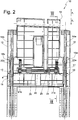
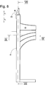
- a vehicle armrest comprises an armrest, which is vertically adjustable by means of an adjusting device 10 in directions z1 and z2.
- the armrest 11 is indicated for clarity only with a dot-dash line.
- the armrest is formed of two parts 11a and 11b.
- the part 11 a of the lid 11 is mounted with a bearing and guide device 12 a and the part 11 b of the lid 11 is mounted with a bearing and guide device 12 b. Because both parts 11a and 11b are mounted in the same way, only the storage of the lid 11a will be described below.
- the part 11a is, for example, pivotably held on a rotor 13 (the rotor of the bearing and guide device 12b is in Fig. 1 not shown).
- the part 11a is in the directions p1 and p2 between an in Fig. 1 shown approximately horizontal position and a pivoted about 90 degrees in the direction p1 vertical position movable.
- the rotor 13 can be moved by means of the bearing and guide device 12a in the direction of z1 and z2.
- the bearing and guide device 12a comprises two guide rods 14a and 14b.
- a side portion 16a of the rotor 13 is in contact with the outer surface 15 of the guide rod 14a
- a side portion 16b of the rotor 13 is in contact with the outer surface 15 of the guide rod 14b.
- the guide rods 14a and 14b which are approximately circular in cross-section, respectively, grip complementary recesses 17 in the side regions 14a and 14b.
- the guide rods 14a and 14b are on a vehicle-fixed base member 18 held.
- the rotor 13 is formed plate-shaped.
- the synchronizing device 19 comprises a shaft 20 which is rotatably mounted on the rotor 13 about the axis of rotation a, at the two end regions of which a toothed wheel 21a and 21b is held non-rotatably, so that the toothed wheels 21a and 21b can not rotate about the axis a relative to one another.
- the synchronizer 19 further includes toothed racks 22a and 22b formed on the base member 18 and inserted into the Fig. 2 and 3 are recognizable.
- the gear 21a is engaged with the rack 22a and the gear 21b is engaged with the rack 22b. In this way, an undesired rotation of the rotor 13 about the y-axis is prevented.
- Fig. 3 is also a rack 23a of the storage and guiding device 12b recognizable.
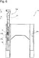
- each runner 13 can be locked in its vertical position.
- the locking device 24 comprises a wrap spring 25, which cooperates with an outer surface 26 of the shaft 20.
- the wrap spring 25 is fixedly secured to the rotor 13 with a spring end. Another spring end can be actuated to adjust the locking device between a locking position and a release position.
- the diameter of the coaxial with the shaft 20 arranged wrap spring 25 is reduced so that the shaft 20 is prevented by the contact of the wrap spring 20 with the outer surface 26 of a movement.
- the shaft 20 can not rotate relative to the rotor 13, and movement of the rotor 13 thereby becomes prevented.
- the diameter of the wrap spring 25 is increased and the shaft 20 can rotate freely.
- the adjustment between the locking position and the release position can be done for example with a switch provided on the outside of the armrest.
- the drive of the rotor 13 is not shown. This can be done manually or by motor. With manual drive, the rotor may be spring loaded. The spring is e.g. with a movement of the rotor 13 in the direction of z2 tensioned and relaxes in a movement in the direction z1.
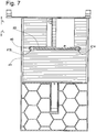
- the second embodiment according to the Fig. 7 to 9 differs essentially by the first embodiment that runners 40 are guided to a base portion 41 like a drawer in the directions z1 and z2 movable.
- the base part 41 forms a shaft as a guide track, whereby side regions 42a and 42b of the rotor 40 are encompassed by U-shaped structures.
- the synchronizer 19 and the locking device 24 are constructed according to the first embodiment.
- the rotor 40 is loaded by a roller spring in the direction z2.
Landscapes
- Engineering & Computer Science (AREA)
- Mechanical Engineering (AREA)
- Aviation & Aerospace Engineering (AREA)
- Transportation (AREA)
- Seats For Vehicles (AREA)
- Vehicle Step Arrangements And Article Storage (AREA)
Abstract
Description
- Die Erfindung betrifft gemäß einem ersten Aspekt eine höhenverstellbare Armlehne.
- Aus dem Stand der Technik sind Armlehnen mit schwenkbarer Armauflage bekannt. Durch schwenken der Armauflage in unterschiedliche Gebrauchspositionen kann auch die Höhe der Armlehne verändert werden. Mit der Veränderung der Schwenkposition geht aber auch eine Winkeländerung einher.
- Des weiteren ist aus dem Stand der Technik eine Mittelkonsole mit Ablagefach und Armauflage bekannt, wobei die gesamte Konsole vertikal auf- und abbewegt werden kann. Diese Vorrichtung ist sehr aufwändig in der Herstellung und damit auch kostenintensiv.
- In der
DE 10 2004 038 059 A1 ist eine Mittelkonsole mit einer höhenverstellbaren Armlehne beschrieben. Die Mittelkonsole umfasst ein inneres und ein äußeres Gehäuseteil, die teleskopartig ineinander verschiebbar sind. Das Gehäuseteil, an welchem die Armlehne gehalten ist, ist dadurch höhenverstellbar. Eine lösbare Arretierung in der eingestellten Höhenposition wird mittels einer Zahnstange erreicht, die mit einem Rastelement zusammenwirkt. - Die
DE 196 11 894 C1 beschreibt eine höhenverstellbare Armlehne als Teil einer Mittelkonsole. Die Armlehne ist mittels einer Hubeinrichtung höhenverstellbar und mit einer Parallelogrammführung zu der Mittelkonsole zwangsgekoppelt. - Die
DE 101 10 330 A1 beschreibt eine Mittelkonsole mit Armauflage und mit einer Vorrichtung zur Höhenverstellung. Die Vorrichtung umfasst ein Zahnradgetriebe, welches mit Zahnstangen in Eingriff steht, die an einem höhenverstellbaren Rahmen angeordnet sind, an dessen oberem Ende die Armauflage angeordnet ist. - Die
DE 100 32 657 A1 offenbart eine Mittelkonsole mit einem durch ein Deckelmodul verschließbaren unteren Staufach. Das Deckelmodul umfasst ein oberes Staufach, welchem ein bewegbarer Deckel zugeordnet ist. Aus einer Schließstellung ist das Deckelmodul in eine Höhenlage verstellbar, in welcher eine in dem oberen Staufach angeordnete Fernsprecheinrichtung in Fahrzeuglängsrichtung aus dem Staufachbewegbar ist. - Es war Aufgabe der Erfindung eine höhenverstellbare Armlehne zu schaffen, die einfach in der Herstellung ist und möglichst unabhängig von anderen Einrichtungen, wie Ablagefach, ist.
- Die Aufgabe wurde gelöst durch eine Armlehne mit den Merkmalen des Anspruchs 1.
- Die erfindungsgemäße Armlehne umfasst eine Armauflage, die mittels einer Verstellvorrichtung vertikal verstellbar an einer Fahrzeugstruktur gehalten ist. Die Verstellung erfolgt dabei z.B. unabhängig von einem Staufach. Auf diese Weise kann die vertikale Position der Armauflage an die Größe des Sitzinsassen angepasst werden. Die Verstellvorrichtung kann z.B. mit einem manuellen Antrieb oder alternativ elektrisch erfolgen. Die Verstellvorrichtung umfasst eine Führung mit wenigstens einer der Fahrzeugstruktur zugeordneten Führungsbahn, an welcher wenigstens ein der Armauflage zugeordneter Läufer vertikal geführt ist.
- Die Führung ist z.B. von einer Linearführung gebildet. Mittels der Linearführung ist der Läufer auf einer linearen Bahn geführt. Die Führungsbahn kann z.B. eine Zahnleiste umfassen, die mit einem Zahnrad in Eingriff steht, welches Teil des Läufers ist. Eine Linearführung stellt eine wenig aufwändige Art der Führung dar.
- Die Führungsanlage ist z.B. von einer Führungsstange gebildet. Die Führungsstange stellt dem Läufer eine große Führungsfläche bereit. Z.B. kann der Läufer den Umfang der Führungsstange wenigstens teilweise umgreifen.
- Die Führungsstange kann z.B. einen kreiszylindrischen Querschnitt oder alternativ andere Querschnittsformen, wie oval, rechteckig, etc. aufweisen. Derartige Führungsstangen sind handelsüblich.
- Die Linearführung umfasst z.B. wenigstens ein erstes Paar und eine zweites Paar von Führungsanlage und Läufer. Dabei synchronisiert z.B. eine Synchronisationsvorrichtung die Bewegung des Läufers des ersten Paares und des zweiten Paares. Hiermit wird ein Verkanten der der Läufer verhindert, so dass sich die Armauflage immer leichtgängig in vertikaler Richtung bewegen lässt.
- Gemäß einer Ausführungsform umfasst das erste Paar und das zweite Paar eine der Führungsbahn zugeordnete Zahnleiste und ein mit der Zahnleiste in Eingriff stehendes Zahnrad, welches dem Läufer zugeordnet ist. Die mit den Zahnleisten in Eingriff stehenden Zahnräder sind untereinander mit einer Zahnradwelle bewegungsverbunden. Auf diese Weise kann kein Verkanten durch unterschiedliche Bewegungen zwischen dem ersten Paar und dem zweiten Paar.
- Die Armauflage ist z.B. mittels einer Arretiervorrichtung in wenigstens einer vertikalen Position festlegbar. Die Arretiervorrichtung umfasst wenigstens ein der Fahrzeugstruktur zugeordnetes erstes Arretiermittel und wenigstens ein der Armauflage zugeordnetes zweites Arretiermittel.
- Die Arretiervorrichtung umfasst z.B. als Arretiermittel eine der Armauflage zugeordnete Schlingfeder, die zwischen einer Arretierposition und einer Löseposition verstellbar ist. Diese ist z.B. der Armauflage zugeordnet, d.h. sie bildet ein zweites Arretiermittel. Die Schlingfeder umwindet z.B. eine Struktur der Führung. In der Arretierposition ist der Durchmesser der Schlingfeder derart reduziert, dass die Schlingfeder in festem Kontakt mit der Außenfläche der Struktur der Führung steht und eine Bewegung der Armauflage verhindert. In der Löseposition ist der Durchmesser der Schlingfeder derart aufgeweitet, dass kein fester Kontakt zu der Außenfläche besteht, wodurch eine Bewegung der Armauflage ermöglicht wird.
- Gemäß einer Ausführungsform wirkt die Schlingfeder mit einer der Fahrzeugstruktur zugeordneten Führungsstange der Führung oder mit einer der Armauflage zugeordneten Zahnradwelle zusammen, wobei die Armauflage in der Arretierposition in der eingestellten vertikalen Position arretiert ist und in der Löseposition in der vertikalen Position verstellbar ist.
- Die Armauflage ist z.B. von wenigstens einer Feder in eine Bewegungsrichtung belastet. Z.B. kann die Armauflage entgegen der Federkraft vertikal nach unten bewegt werden, wobei die Feder gespannt wird. Bei einer Bewegung der Armauflage nach oben unterstützt die Federkraft die Aufwärtsbewegung.
- Weitere Vorteile der Erfindung ergeben sich aus der nachfolgenden Beschreibung eines in den Fig. schematisch dargestellten Ausführungsbeispiels. Es zeigen:
-
Fig. 1 eine Seitenansicht eines ersten Ausführungsbeispiels einer Verstellvorrichtung für eine Armlehne in einer ersten vertikalen Höhenposition, -
Fig. 2 eine Schnittdarstellung gemäß Schnittlinie II - II inFig. 1 , -
Fig. 3 eine Schnittdarstellung gemäß Schnittlinie III - III inFig. 2 , -
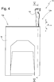
Fig. 4 in Anlehnung anFig. 1 die Verstellvorrichtung in einer zweiten Höhenposition, -
Fig. 5 eine Schnittdarstellung gemäß Schnittlinie V - V inFig. 4 , -
Fig. 6 eine Schnittdarstellung gemäß Schnittlinie VI - VI inFig. 5 -
Fig. 7 eine Schnittdarstellung gemäß Schnittlinie VII - VII inFig. 8 , -
Fig. 8 eine Seitenansicht eines zweiten Ausführungsbeispiels einer Verstellvorrichtung für eine Armlehne, -
Fig. 9 eine Schnittansicht gemäß Schnittlinie IX - IX inFig. 8 . - Eine Fahrzeugarmlehne umfasst eine Armauflage, die mittels einer Verstellvorrichtung 10 vertikal in Richtungen z1 und z2 vertikal verstellbar ist. In
Fig. 1 ist die Armauflage 11 der Übersichtlichkeit halber lediglich mit einer strichpunktierten Linie angedeutet. Im vorliegenden Ausführungsbeispiel ist die Armauflage aus zwei Teilen 11a und 11b gebildet. - Der Teil 11 a des Deckels 11 ist mit einer Lager- und Führungsvorrichtung 12a und der Teil 11b des Deckels 11 ist mit einer Lager- und Führungsvorrichtung 12b gelagert. Weil beide Teile 11a und 11b in gleicher Weise gelagert sind, soll nachfolgend lediglich die Lagerung des Deckels 11a beschrieben werden. Der Teil 11a ist an einem Läufer 13 z.B. schwenkbar gehalten (der Läufer der Lager- und Führungsvorrichtung 12b ist in
Fig. 1 nicht dargestellt). Der Teil 11a ist in die Richtungen p1 und p2 zwischen einer inFig. 1 dargestellten etwa horizontalen Position und einer etwa um 90 Grad in Richtung p1 verschwenkten vertikalen Position bewegbar. - Der Läufer 13 kann mittels der Lager- und Führungsvorrichtung 12a in Richtung z1 und z2 bewegt werden. In
Fig. 2 ist erkennbar, dass die Lager- und Führungsvorrichtung 12a zwei Führungsstangen 14a und 14b umfasst. Ein Seitenbereich 16a des Läufers 13 steht mit der Außenfläche 15 der Führungsstange 14a und ein Seitenbereich 16b des Läufers 13 steht mit der Außenfläche 15 der Führungsstange 14b in Kontakt. Die im Querschnitt etwa kreiszylindrischen Führungsstangen 14a und 14b durgreifen jeweils komplementäre Aussparungen 17 in den Seitenbereichen 14a und 14b. Die Führungsstangen 14a und 14b sind an einem fahrzeugfesten Basisteil 18 gehalten. InFig. 2 ist erkennbar, dass der Läufer 13 plattenflörmig ausgebildet ist. - Mit einer Synchronvorrichtung 19 soll ein Verkanten des Läufers 13 relativ zu den Führungsstangen 14a und 14b verhindert werden. Die Synchronvorrichtung 19 umfasst eine an dem Läufer 13 um die Drehachse a drehbar gelagerte Welle 20 an deren beiden Endbereichen jeweils ein Zahnrad 21a und 21b drehfest gehalten ist, so dass sich die Zahnräder 21a und 21b nicht relativ zueinander um die Achse a drehen können. Die Synchronvorrichtung 19 umfasst ferner an dem Basisteil 18 ausgebildete Zahnleisten 22a und 22b, die in den
Fig. 2 und3 erkennbar sind. Das Zahnrad 21a steht mit der Zahnleiste 22a und das Zahnrad 21b mit der Zahnleiste 22b in Eingriff. Auf diese Weise wird eine unerwünschte Drehung des Läufers 13 um die y-Achse verhindert. InFig. 3 ist auch eine Zahnleiste 23a der Lager- und Führungsvorrichtung 12b erkennbar. - In den
Fig. 4 bis 6 ist der Läufer 13 bezüglich derFig. 1 bis 3 in Richtung z1 verlagert dargestellt. Aus der in denFig. 4 bis 6 dargestellten Position kann der Läufer 13 in Richtung z2 in die Position untere Endposition gemäß derFig. 1 bis 3 verstellt werden. - Mittels einer Arretiervorrichtung 24 kann jeder Läufer 13 in seiner vertikalen Position arretiert werden. Im vorliegenden Ausführungsbeispiel umfasst die Arretiervorrichtung 24 eine Schlingfeder 25, die mit einer Außenfläche 26 der Welle 20 zusammenwirkt. Die Schlingfeder 25 ist mit einem Federende fest an dem Läufer 13 befestigt. Ein anderes Federende kann betätigt werden, um die Arretiervorrichtung zwischen einer Arretierposition und einer Löseposition zu verstellen. In der Arretierposition ist der Durchmesser der koaxial zu der Welle 20 angeordneten Schlingfeder 25 so verringert, dass die Welle 20 durch den Kontakt der Schlingfeder 20 mit der Außenfläche 26 an einer Bewegung gehindert wird. Mit anderen Worten, die Welle 20 kann sich nicht relativ zu dem Läufer 13 drehen und eine Bewegung des Läufers 13 wird dadurch verhindert. In der Löseposition ist der Durchmesser der Schlingfeder 25 vergrößert und die Welle 20 kann sich frei drehen. Die Verstellung zwischen der Arretierposition und der Löseposition kann z.B. mit einem außen an der Armlehne vorgesehenen Schalter erfolgen.
- Der Antrieb der Läufer 13 ist nicht dargestellt. Dieser kann manuell oder motorisch erfolgen. Bei manuellem Antrieb kann der Läufer federbelastet sein. Die Feder wird z.B. bei einer Bewegung des Läufers 13 in Richtung z2 gespannt und entspannt sich bei einer Bewegung in Richtung z1.
- Das zweite Ausführungsbeispiel gemäß der
Fig. 7 bis 9 unterscheidet sich im Wesentlichen dadurch von dem ersten Ausführungsbeispiel, dass Läufer 40 an einem Basisteil 41 schubladenartig in die Richtungen z1 und z2 bewegbar geführt sind. Das Basisteil 41 bildet ein Schacht als Führungsbahn aus, wodurch Seitenbereiche 42a und 42b des Läufers 40 von u-förmigen Strukturen umgriffen werden. Die Synchronvorrichtung 19 und die Arretiervorrichtung 24 ist entsprechend dem ersten Ausführungsbeispiel aufgebaut. Bei dem zweiten Ausführungsbeispiel ist der Läufer 40 von einer Rollfeder in Richtung z2 belastet.
Claims (10)
- Armlehne mit einer Armauflage (11), die mittels einer Verstellvorrichtung (10) vertikal (z1, z2) verstellbar an einer Fahrzeugstruktur gehalten ist, wobei die Verstellvorrichtung eine Führung mit wenigstens einer der Fahrzeugstruktur zugeordneten Führungsbahn umfasst, an welcher wenigstens ein der Armauflage (11) zugeordneter Läufer (13) vertikal geführt ist.
- Armlehne nach Anspruch 1, dadurch gekennzeichnet, dass die Führung von einer Linearführung gebildet ist.
- Armlehne nach einem der vorhergehenden Ansprüche, dadurch gekennzeichnet, dass die Führungsbahn von wenigstens einer Führungsstange (14a, 14b) gebildet ist.
- Armlehne nach Anspruch 3, dadurch gekennzeichnet, dass die Führungsstange (14a, 14b) einen kreiszylindrischen Querschnitt aufweist.
- Armlehne nach einem der vorhergehenden Ansprüche, dadurch gekennzeichnet, dass die Verstellvorrichtung wenigstens ein erstes Paar und eine zweites Paar von Führungsbahn und Läufer umfasst und dass eine Synchronisationsvorrichtung die Bewegung des Läufers des ersten Paares und des zweiten Paares synchronisiert.
- Armlehne nach Anspruch 5, dadurch gekennzeichnet, dass das erste Paar und das zweite paar eine Zahnleiste und ein mit der Zahnleiste in Eingriff stehendes Zahnrad umfasst und dass die Zahnräder mit einer Zahnradwelle bewegungsverbunden sind.
- Armlehne nach einem der vorhergehenden Ansprüche, dadurch gekennzeichnet, dass die Armauflage mittels einer Arretiervorrichtung in wenigstens einer vertikalen Position festlegbar ist.
- Armlehne nach Anspruch 7, dadurch gekennzeichnet, dass die Arretiervorrichtung eine der Armauflage zugeordnete Schlingfeder umfasst.
- Armlehne nach Anspruch 8, dadurch gekennzeichnet, dass die Schlingfeder mit der Führungsstange oder mit der Zahnradwelle zusammenwirkt und zwischen einer Arretierposition und einer Löseposition verstellbar ist, wobei die Armauflage in der Arretierposition in der eingestellten vertikalen Position arretiert ist und in der Löseposition in vertikaler Richtung (z1, z2) verstellbar ist.
- Armlehne nach einem der vorhergehenden Ansprüche, dadurch gekennzeichnet, dass die Armauflage von wenigstens einer Feder in eine Bewegungsrichtung belastet ist.
Applications Claiming Priority (1)
| Application Number | Priority Date | Filing Date | Title |
|---|---|---|---|
| DE102016006230.4A DE102016006230A1 (de) | 2016-05-13 | 2016-05-13 | Armlehne |
Publications (2)
| Publication Number | Publication Date |
|---|---|
| EP3243696A1 true EP3243696A1 (de) | 2017-11-15 |
| EP3243696B1 EP3243696B1 (de) | 2021-10-06 |
Family
ID=58530350
Family Applications (1)
| Application Number | Title | Priority Date | Filing Date |
|---|---|---|---|
| EP17000602.7A Active EP3243696B1 (de) | 2016-05-13 | 2017-04-07 | Armlehne |
Country Status (4)
| Country | Link |
|---|---|
| US (1) | US10406985B2 (de) |
| EP (1) | EP3243696B1 (de) |
| CN (1) | CN107364376B (de) |
| DE (1) | DE102016006230A1 (de) |
Families Citing this family (4)
| Publication number | Priority date | Publication date | Assignee | Title |
|---|---|---|---|---|
| US10730627B2 (en) * | 2015-04-13 | 2020-08-04 | Safran Seats | Seat module comprising an armrest with an optimised design |
| DE102018221340A1 (de) * | 2018-12-10 | 2020-06-10 | Brose Fahrzeugteile SE & Co. Kommanditgesellschaft, Coburg | Konsole für ein Kraftfahrzeug |
| FR3096619B1 (fr) * | 2019-05-27 | 2024-08-02 | Faurecia Sieges Dautomobile | Ensemble d’accoudoir pour siege de vehicule |
| DE102020203129A1 (de) | 2020-03-11 | 2021-09-16 | Bos Gmbh & Co. Kg | Armauflagevorrichtung für einen Fahrzeuginnenraum |
Citations (8)
| Publication number | Priority date | Publication date | Assignee | Title |
|---|---|---|---|---|
| DE19611894C1 (de) | 1996-03-26 | 1997-07-10 | Daimler Benz Ag | Mittelkonsole für einen Innenraum eines Personenkraftwagens |
| DE10032657A1 (de) | 2000-07-05 | 2002-01-24 | Daimler Chrysler Ag | Mittelkonsole in einem Kraftfahrzeuginnenraum |
| DE10110330A1 (de) | 2001-03-03 | 2002-10-24 | Bayerische Motoren Werke Ag | Mittelkonsole für einen Innenraum eines Fahrzeuges |
| FR2841511A1 (fr) * | 2002-06-26 | 2004-01-02 | Cera | Accoudoire reglable en hauteur, notamment pour siege de vehicule automobile |
| DE102004038059A1 (de) | 2004-07-30 | 2006-02-16 | Faurecia Innenraum Systeme Gmbh | Mittelkonsole mit einer höhenverstellbaren Armlehne |
| EP1676743A1 (de) * | 2004-12-30 | 2006-07-05 | Grupo Antolin Ingenieria, S.A. | Höhenverstellbare Armlehne für eine Fahrzeugtür |
| EP2003015A2 (de) * | 2007-06-12 | 2008-12-17 | BOS GmbH & Co. KG | Verstellbare Seitenarmlehne |
| DE102008056290A1 (de) * | 2008-11-07 | 2010-05-12 | Grammer Ag | Ausstattungsteil für Fahrzeuge |
Family Cites Families (10)
| Publication number | Priority date | Publication date | Assignee | Title |
|---|---|---|---|---|
| US4659135A (en) * | 1984-01-20 | 1987-04-21 | Schmelzer Corporation | Adjustable arm rest |
| US4907835A (en) * | 1988-08-08 | 1990-03-13 | Charles Salters | Portable arm rest apparatus |
| DE3930270A1 (de) * | 1989-09-11 | 1991-03-21 | Happich Gmbh Gebr | Armlehne insbesondere fuer fahrzeuge |
| CN2214337Y (zh) * | 1994-09-23 | 1995-12-06 | 宋宁 | 摩托车或自行车后座扶手 |
| FR2860194B1 (fr) * | 2003-09-26 | 2007-02-09 | Airbus | Siege convertible destine a recevoir un passager d'aeronef |
| DE102004025052A1 (de) * | 2004-05-18 | 2005-12-15 | Grammer Ag | Vorrichtung zur Höhenverstellung einer Auflagefläche einer Kfz-Armlehne |
| US7387342B1 (en) * | 2007-04-13 | 2008-06-17 | Robert Clough | Seat armrest |
| DE102008023751A1 (de) * | 2008-05-15 | 2009-11-19 | Grammer Ag | Ausstattungsvorrichtung für einen Fahrzeuginnenraum, insbesondere Armlehne für Fahrzeugsitze |
| DE102008050953B4 (de) * | 2008-10-10 | 2019-09-19 | Brose Fahrzeugteile Gmbh & Co. Kommanditgesellschaft, Coburg | Höhenverstellbare Mittelarmlehne für ein Kraftfahrzeug |
| JP6431347B2 (ja) * | 2014-11-26 | 2018-11-28 | 株式会社タチエス | アームレスト付きシート及びそれに用いるアームレストのロック解除装置 |
-
2016
- 2016-05-13 DE DE102016006230.4A patent/DE102016006230A1/de not_active Withdrawn
-
2017
- 2017-04-07 EP EP17000602.7A patent/EP3243696B1/de active Active
- 2017-04-27 CN CN201710284436.1A patent/CN107364376B/zh active Active
- 2017-05-11 US US15/592,854 patent/US10406985B2/en active Active
Patent Citations (8)
| Publication number | Priority date | Publication date | Assignee | Title |
|---|---|---|---|---|
| DE19611894C1 (de) | 1996-03-26 | 1997-07-10 | Daimler Benz Ag | Mittelkonsole für einen Innenraum eines Personenkraftwagens |
| DE10032657A1 (de) | 2000-07-05 | 2002-01-24 | Daimler Chrysler Ag | Mittelkonsole in einem Kraftfahrzeuginnenraum |
| DE10110330A1 (de) | 2001-03-03 | 2002-10-24 | Bayerische Motoren Werke Ag | Mittelkonsole für einen Innenraum eines Fahrzeuges |
| FR2841511A1 (fr) * | 2002-06-26 | 2004-01-02 | Cera | Accoudoire reglable en hauteur, notamment pour siege de vehicule automobile |
| DE102004038059A1 (de) | 2004-07-30 | 2006-02-16 | Faurecia Innenraum Systeme Gmbh | Mittelkonsole mit einer höhenverstellbaren Armlehne |
| EP1676743A1 (de) * | 2004-12-30 | 2006-07-05 | Grupo Antolin Ingenieria, S.A. | Höhenverstellbare Armlehne für eine Fahrzeugtür |
| EP2003015A2 (de) * | 2007-06-12 | 2008-12-17 | BOS GmbH & Co. KG | Verstellbare Seitenarmlehne |
| DE102008056290A1 (de) * | 2008-11-07 | 2010-05-12 | Grammer Ag | Ausstattungsteil für Fahrzeuge |
Also Published As
| Publication number | Publication date |
|---|---|
| US20170327015A1 (en) | 2017-11-16 |
| CN107364376B (zh) | 2021-07-13 |
| US10406985B2 (en) | 2019-09-10 |
| EP3243696B1 (de) | 2021-10-06 |
| DE102016006230A1 (de) | 2017-11-16 |
| CN107364376A (zh) | 2017-11-21 |
Similar Documents
| Publication | Publication Date | Title |
|---|---|---|
| DE202007013356U1 (de) | Vorrichtung zur Verstellung eines Bodens oder Abstellers eines Kühl- und/oder Gefriergerätes | |
| DE2716549B2 (de) | Vorrichtung zur Führung und Verriegelung von längsverschiebbaren Fahrzeugsitzen | |
| EP3243696A1 (de) | Armlehne | |
| EP2979907A1 (de) | Beschattungsvorrichtung für eine heckscheibenanordnung eines kraftfahrzeugs | |
| DE102023118830B3 (de) | Vorrichtung zum Einstellen einer Displayanordnung für ein Fahrzeugdach und Fahrzeugdach für ein Kraftfahrzeug | |
| DE19826823C1 (de) | Sitztiefenverstellvorrichtung für einen Kraftfahrzeugsitz | |
| EP1048510B1 (de) | Kraftfahrzeug-Rücksitzbank | |
| DE4305909C2 (de) | Verstellbare Kraftfahrzeug-Kopfstütze | |
| DE102013105095B4 (de) | Verstellvorrichtung für einen Fahrzeugsitz | |
| DE102010044448B4 (de) | In X-Richtung verstellbare Kopfstütze und Arretierungssystem | |
| DE19845930C2 (de) | Becherhalteranordnung für ein Kraftfahrzeug | |
| DE1680791C3 (de) | Führungsvorrichtung für Kraftfahrzeugfenster | |
| EP3183133B1 (de) | Gleiter zum führen eines verlagerbaren elements | |
| EP1225089B1 (de) | Armlehne mit beweglicher Armauflage, insbesondere für Fahrzeuge | |
| DE102021134096B4 (de) | Ausstattungsteil für ein Fahrzeug | |
| DE10065130B4 (de) | Windschild für Motorräder | |
| DE3927253C2 (de) | ||
| EP3908480B1 (de) | Verstellmechanismus und kopfstütze | |
| DE102009036896B3 (de) | Kopfstütze für Fahrzeugsitze | |
| DE102019110765B4 (de) | Fahrzeugsitz mit verlagerbarem Rückenlehnenoberteil | |
| DE102017112081A1 (de) | Sitz für ein Kraftfahrzeug | |
| EP3572056B1 (de) | Tragenlagerungseinrichtung | |
| DE102020100562A1 (de) | Beinauflagebeschlag | |
| DE102012011200B4 (de) | Kopfstütze | |
| DE102014207306B4 (de) | Klapptisch und Fahrzeugsitz |
Legal Events
| Date | Code | Title | Description |
|---|---|---|---|
| PUAI | Public reference made under article 153(3) epc to a published international application that has entered the european phase |
Free format text: ORIGINAL CODE: 0009012 |
|
| STAA | Information on the status of an ep patent application or granted ep patent |
Free format text: STATUS: THE APPLICATION HAS BEEN PUBLISHED |
|
| AK | Designated contracting states |
Kind code of ref document: A1 Designated state(s): AL AT BE BG CH CY CZ DE DK EE ES FI FR GB GR HR HU IE IS IT LI LT LU LV MC MK MT NL NO PL PT RO RS SE SI SK SM TR |
|
| AX | Request for extension of the european patent |
Extension state: BA ME |
|
| STAA | Information on the status of an ep patent application or granted ep patent |
Free format text: STATUS: REQUEST FOR EXAMINATION WAS MADE |
|
| 17P | Request for examination filed |
Effective date: 20180515 |
|
| RBV | Designated contracting states (corrected) |
Designated state(s): AL AT BE BG CH CY CZ DE DK EE ES FI FR GB GR HR HU IE IS IT LI LT LU LV MC MK MT NL NO PL PT RO RS SE SI SK SM TR |
|
| STAA | Information on the status of an ep patent application or granted ep patent |
Free format text: STATUS: EXAMINATION IS IN PROGRESS |
|
| 17Q | First examination report despatched |
Effective date: 20191202 |
|
| RAP1 | Party data changed (applicant data changed or rights of an application transferred) |
Owner name: GRAMMER AG |
|
| REG | Reference to a national code |
Ref country code: DE Ref legal event code: R079 Ref document number: 502017011630 Country of ref document: DE Free format text: PREVIOUS MAIN CLASS: B60N0002460000 Ipc: B60N0002750000 |
|
| GRAP | Despatch of communication of intention to grant a patent |
Free format text: ORIGINAL CODE: EPIDOSNIGR1 |
|
| STAA | Information on the status of an ep patent application or granted ep patent |
Free format text: STATUS: GRANT OF PATENT IS INTENDED |
|
| RIC1 | Information provided on ipc code assigned before grant |
Ipc: B60N 2/75 20180101AFI20210616BHEP |
|
| INTG | Intention to grant announced |
Effective date: 20210716 |
|
| GRAS | Grant fee paid |
Free format text: ORIGINAL CODE: EPIDOSNIGR3 |
|
| GRAA | (expected) grant |
Free format text: ORIGINAL CODE: 0009210 |
|
| STAA | Information on the status of an ep patent application or granted ep patent |
Free format text: STATUS: THE PATENT HAS BEEN GRANTED |
|
| AK | Designated contracting states |
Kind code of ref document: B1 Designated state(s): AL AT BE BG CH CY CZ DE DK EE ES FI FR GB GR HR HU IE IS IT LI LT LU LV MC MK MT NL NO PL PT RO RS SE SI SK SM TR |
|
| REG | Reference to a national code |
Ref country code: GB Ref legal event code: FG4D Free format text: NOT ENGLISH |
|
| REG | Reference to a national code |
Ref country code: CH Ref legal event code: EP Ref country code: AT Ref legal event code: REF Ref document number: 1435942 Country of ref document: AT Kind code of ref document: T Effective date: 20211015 |
|
| REG | Reference to a national code |
Ref country code: IE Ref legal event code: FG4D Free format text: LANGUAGE OF EP DOCUMENT: GERMAN |
|
| REG | Reference to a national code |
Ref country code: DE Ref legal event code: R096 Ref document number: 502017011630 Country of ref document: DE |
|
| REG | Reference to a national code |
Ref country code: LT Ref legal event code: MG9D |
|
| REG | Reference to a national code |
Ref country code: NL Ref legal event code: MP Effective date: 20211006 |
|
| PG25 | Lapsed in a contracting state [announced via postgrant information from national office to epo] |
Ref country code: RS Free format text: LAPSE BECAUSE OF FAILURE TO SUBMIT A TRANSLATION OF THE DESCRIPTION OR TO PAY THE FEE WITHIN THE PRESCRIBED TIME-LIMIT Effective date: 20211006 Ref country code: LT Free format text: LAPSE BECAUSE OF FAILURE TO SUBMIT A TRANSLATION OF THE DESCRIPTION OR TO PAY THE FEE WITHIN THE PRESCRIBED TIME-LIMIT Effective date: 20211006 Ref country code: FI Free format text: LAPSE BECAUSE OF FAILURE TO SUBMIT A TRANSLATION OF THE DESCRIPTION OR TO PAY THE FEE WITHIN THE PRESCRIBED TIME-LIMIT Effective date: 20211006 Ref country code: BG Free format text: LAPSE BECAUSE OF FAILURE TO SUBMIT A TRANSLATION OF THE DESCRIPTION OR TO PAY THE FEE WITHIN THE PRESCRIBED TIME-LIMIT Effective date: 20220106 |
|
| PG25 | Lapsed in a contracting state [announced via postgrant information from national office to epo] |
Ref country code: IS Free format text: LAPSE BECAUSE OF FAILURE TO SUBMIT A TRANSLATION OF THE DESCRIPTION OR TO PAY THE FEE WITHIN THE PRESCRIBED TIME-LIMIT Effective date: 20220206 Ref country code: SE Free format text: LAPSE BECAUSE OF FAILURE TO SUBMIT A TRANSLATION OF THE DESCRIPTION OR TO PAY THE FEE WITHIN THE PRESCRIBED TIME-LIMIT Effective date: 20211006 Ref country code: PT Free format text: LAPSE BECAUSE OF FAILURE TO SUBMIT A TRANSLATION OF THE DESCRIPTION OR TO PAY THE FEE WITHIN THE PRESCRIBED TIME-LIMIT Effective date: 20220207 Ref country code: PL Free format text: LAPSE BECAUSE OF FAILURE TO SUBMIT A TRANSLATION OF THE DESCRIPTION OR TO PAY THE FEE WITHIN THE PRESCRIBED TIME-LIMIT Effective date: 20211006 Ref country code: NO Free format text: LAPSE BECAUSE OF FAILURE TO SUBMIT A TRANSLATION OF THE DESCRIPTION OR TO PAY THE FEE WITHIN THE PRESCRIBED TIME-LIMIT Effective date: 20220106 Ref country code: NL Free format text: LAPSE BECAUSE OF FAILURE TO SUBMIT A TRANSLATION OF THE DESCRIPTION OR TO PAY THE FEE WITHIN THE PRESCRIBED TIME-LIMIT Effective date: 20211006 Ref country code: LV Free format text: LAPSE BECAUSE OF FAILURE TO SUBMIT A TRANSLATION OF THE DESCRIPTION OR TO PAY THE FEE WITHIN THE PRESCRIBED TIME-LIMIT Effective date: 20211006 Ref country code: HR Free format text: LAPSE BECAUSE OF FAILURE TO SUBMIT A TRANSLATION OF THE DESCRIPTION OR TO PAY THE FEE WITHIN THE PRESCRIBED TIME-LIMIT Effective date: 20211006 Ref country code: GR Free format text: LAPSE BECAUSE OF FAILURE TO SUBMIT A TRANSLATION OF THE DESCRIPTION OR TO PAY THE FEE WITHIN THE PRESCRIBED TIME-LIMIT Effective date: 20220107 Ref country code: ES Free format text: LAPSE BECAUSE OF FAILURE TO SUBMIT A TRANSLATION OF THE DESCRIPTION OR TO PAY THE FEE WITHIN THE PRESCRIBED TIME-LIMIT Effective date: 20211006 |
|
| REG | Reference to a national code |
Ref country code: DE Ref legal event code: R097 Ref document number: 502017011630 Country of ref document: DE |
|
| PG25 | Lapsed in a contracting state [announced via postgrant information from national office to epo] |
Ref country code: SM Free format text: LAPSE BECAUSE OF FAILURE TO SUBMIT A TRANSLATION OF THE DESCRIPTION OR TO PAY THE FEE WITHIN THE PRESCRIBED TIME-LIMIT Effective date: 20211006 Ref country code: SK Free format text: LAPSE BECAUSE OF FAILURE TO SUBMIT A TRANSLATION OF THE DESCRIPTION OR TO PAY THE FEE WITHIN THE PRESCRIBED TIME-LIMIT Effective date: 20211006 Ref country code: RO Free format text: LAPSE BECAUSE OF FAILURE TO SUBMIT A TRANSLATION OF THE DESCRIPTION OR TO PAY THE FEE WITHIN THE PRESCRIBED TIME-LIMIT Effective date: 20211006 Ref country code: EE Free format text: LAPSE BECAUSE OF FAILURE TO SUBMIT A TRANSLATION OF THE DESCRIPTION OR TO PAY THE FEE WITHIN THE PRESCRIBED TIME-LIMIT Effective date: 20211006 Ref country code: DK Free format text: LAPSE BECAUSE OF FAILURE TO SUBMIT A TRANSLATION OF THE DESCRIPTION OR TO PAY THE FEE WITHIN THE PRESCRIBED TIME-LIMIT Effective date: 20211006 Ref country code: CZ Free format text: LAPSE BECAUSE OF FAILURE TO SUBMIT A TRANSLATION OF THE DESCRIPTION OR TO PAY THE FEE WITHIN THE PRESCRIBED TIME-LIMIT Effective date: 20211006 |
|
| PLBE | No opposition filed within time limit |
Free format text: ORIGINAL CODE: 0009261 |
|
| STAA | Information on the status of an ep patent application or granted ep patent |
Free format text: STATUS: NO OPPOSITION FILED WITHIN TIME LIMIT |
|
| 26N | No opposition filed |
Effective date: 20220707 |
|
| PG25 | Lapsed in a contracting state [announced via postgrant information from national office to epo] |
Ref country code: AL Free format text: LAPSE BECAUSE OF FAILURE TO SUBMIT A TRANSLATION OF THE DESCRIPTION OR TO PAY THE FEE WITHIN THE PRESCRIBED TIME-LIMIT Effective date: 20211006 |
|
| PG25 | Lapsed in a contracting state [announced via postgrant information from national office to epo] |
Ref country code: SI Free format text: LAPSE BECAUSE OF FAILURE TO SUBMIT A TRANSLATION OF THE DESCRIPTION OR TO PAY THE FEE WITHIN THE PRESCRIBED TIME-LIMIT Effective date: 20211006 |
|
| REG | Reference to a national code |
Ref country code: CH Ref legal event code: PL |
|
| GBPC | Gb: european patent ceased through non-payment of renewal fee |
Effective date: 20220407 |
|
| REG | Reference to a national code |
Ref country code: BE Ref legal event code: MM Effective date: 20220430 |
|
| PG25 | Lapsed in a contracting state [announced via postgrant information from national office to epo] |
Ref country code: MC Free format text: LAPSE BECAUSE OF FAILURE TO SUBMIT A TRANSLATION OF THE DESCRIPTION OR TO PAY THE FEE WITHIN THE PRESCRIBED TIME-LIMIT Effective date: 20211006 Ref country code: LU Free format text: LAPSE BECAUSE OF NON-PAYMENT OF DUE FEES Effective date: 20220407 Ref country code: LI Free format text: LAPSE BECAUSE OF NON-PAYMENT OF DUE FEES Effective date: 20220430 Ref country code: GB Free format text: LAPSE BECAUSE OF NON-PAYMENT OF DUE FEES Effective date: 20220407 Ref country code: FR Free format text: LAPSE BECAUSE OF NON-PAYMENT OF DUE FEES Effective date: 20220430 Ref country code: CH Free format text: LAPSE BECAUSE OF NON-PAYMENT OF DUE FEES Effective date: 20220430 |
|
| PG25 | Lapsed in a contracting state [announced via postgrant information from national office to epo] |
Ref country code: BE Free format text: LAPSE BECAUSE OF NON-PAYMENT OF DUE FEES Effective date: 20220430 |
|
| PG25 | Lapsed in a contracting state [announced via postgrant information from national office to epo] |
Ref country code: IE Free format text: LAPSE BECAUSE OF NON-PAYMENT OF DUE FEES Effective date: 20220407 |
|
| PG25 | Lapsed in a contracting state [announced via postgrant information from national office to epo] |
Ref country code: IT Free format text: LAPSE BECAUSE OF FAILURE TO SUBMIT A TRANSLATION OF THE DESCRIPTION OR TO PAY THE FEE WITHIN THE PRESCRIBED TIME-LIMIT Effective date: 20211006 |
|
| REG | Reference to a national code |
Ref country code: AT Ref legal event code: MM01 Ref document number: 1435942 Country of ref document: AT Kind code of ref document: T Effective date: 20220407 |
|
| PG25 | Lapsed in a contracting state [announced via postgrant information from national office to epo] |
Ref country code: AT Free format text: LAPSE BECAUSE OF NON-PAYMENT OF DUE FEES Effective date: 20220407 |
|
| PG25 | Lapsed in a contracting state [announced via postgrant information from national office to epo] |
Ref country code: HU Free format text: LAPSE BECAUSE OF FAILURE TO SUBMIT A TRANSLATION OF THE DESCRIPTION OR TO PAY THE FEE WITHIN THE PRESCRIBED TIME-LIMIT; INVALID AB INITIO Effective date: 20170407 |
|
| PG25 | Lapsed in a contracting state [announced via postgrant information from national office to epo] |
Ref country code: MK Free format text: LAPSE BECAUSE OF FAILURE TO SUBMIT A TRANSLATION OF THE DESCRIPTION OR TO PAY THE FEE WITHIN THE PRESCRIBED TIME-LIMIT Effective date: 20211006 Ref country code: CY Free format text: LAPSE BECAUSE OF FAILURE TO SUBMIT A TRANSLATION OF THE DESCRIPTION OR TO PAY THE FEE WITHIN THE PRESCRIBED TIME-LIMIT Effective date: 20211006 |
|
| PG25 | Lapsed in a contracting state [announced via postgrant information from national office to epo] |
Ref country code: MT Free format text: LAPSE BECAUSE OF FAILURE TO SUBMIT A TRANSLATION OF THE DESCRIPTION OR TO PAY THE FEE WITHIN THE PRESCRIBED TIME-LIMIT Effective date: 20211006 |
|
| PGFP | Annual fee paid to national office [announced via postgrant information from national office to epo] |
Ref country code: TR Payment date: 20250327 Year of fee payment: 9 |
|
| PGFP | Annual fee paid to national office [announced via postgrant information from national office to epo] |
Ref country code: DE Payment date: 20250417 Year of fee payment: 9 |