EP3243804B1 - Procédé d'allongement pour produire un composant optique en verre - Google Patents
Procédé d'allongement pour produire un composant optique en verre Download PDFInfo
- Publication number
- EP3243804B1 EP3243804B1 EP17168145.5A EP17168145A EP3243804B1 EP 3243804 B1 EP3243804 B1 EP 3243804B1 EP 17168145 A EP17168145 A EP 17168145A EP 3243804 B1 EP3243804 B1 EP 3243804B1
- Authority
- EP
- European Patent Office
- Prior art keywords
- preform
- furnace
- sacrificial tip
- primary rod
- rod
- Prior art date
- Legal status (The legal status is an assumption and is not a legal conclusion. Google has not performed a legal analysis and makes no representation as to the accuracy of the status listed.)
- Active
Links
Images








Classifications
-
- C—CHEMISTRY; METALLURGY
- C03—GLASS; MINERAL OR SLAG WOOL
- C03B—MANUFACTURE, SHAPING, OR SUPPLEMENTARY PROCESSES
- C03B37/00—Manufacture or treatment of flakes, fibres, or filaments from softened glass, minerals, or slags
- C03B37/01—Manufacture of glass fibres or filaments
- C03B37/012—Manufacture of preforms for drawing fibres or filaments
-
- C—CHEMISTRY; METALLURGY
- C03—GLASS; MINERAL OR SLAG WOOL
- C03B—MANUFACTURE, SHAPING, OR SUPPLEMENTARY PROCESSES
- C03B37/00—Manufacture or treatment of flakes, fibres, or filaments from softened glass, minerals, or slags
- C03B37/01—Manufacture of glass fibres or filaments
- C03B37/02—Manufacture of glass fibres or filaments by drawing or extruding, e.g. direct drawing of molten glass from nozzles; Cooling fins therefor
- C03B37/025—Manufacture of glass fibres or filaments by drawing or extruding, e.g. direct drawing of molten glass from nozzles; Cooling fins therefor from reheated softened tubes, rods, fibres or filaments, e.g. drawing fibres from preforms
-
- C—CHEMISTRY; METALLURGY
- C03—GLASS; MINERAL OR SLAG WOOL
- C03B—MANUFACTURE, SHAPING, OR SUPPLEMENTARY PROCESSES
- C03B37/00—Manufacture or treatment of flakes, fibres, or filaments from softened glass, minerals, or slags
- C03B37/01—Manufacture of glass fibres or filaments
- C03B37/012—Manufacture of preforms for drawing fibres or filaments
- C03B37/01205—Manufacture of preforms for drawing fibres or filaments starting from tubes, rods, fibres or filaments
-
- C—CHEMISTRY; METALLURGY
- C03—GLASS; MINERAL OR SLAG WOOL
- C03B—MANUFACTURE, SHAPING, OR SUPPLEMENTARY PROCESSES
- C03B37/00—Manufacture or treatment of flakes, fibres, or filaments from softened glass, minerals, or slags
- C03B37/01—Manufacture of glass fibres or filaments
- C03B37/012—Manufacture of preforms for drawing fibres or filaments
- C03B37/01205—Manufacture of preforms for drawing fibres or filaments starting from tubes, rods, fibres or filaments
- C03B37/01225—Means for changing or stabilising the shape, e.g. diameter, of tubes or rods in general, e.g. collapsing
-
- C—CHEMISTRY; METALLURGY
- C03—GLASS; MINERAL OR SLAG WOOL
- C03B—MANUFACTURE, SHAPING, OR SUPPLEMENTARY PROCESSES
- C03B37/00—Manufacture or treatment of flakes, fibres, or filaments from softened glass, minerals, or slags
- C03B37/01—Manufacture of glass fibres or filaments
- C03B37/02—Manufacture of glass fibres or filaments by drawing or extruding, e.g. direct drawing of molten glass from nozzles; Cooling fins therefor
- C03B37/025—Manufacture of glass fibres or filaments by drawing or extruding, e.g. direct drawing of molten glass from nozzles; Cooling fins therefor from reheated softened tubes, rods, fibres or filaments, e.g. drawing fibres from preforms
- C03B37/027—Fibres composed of different sorts of glass, e.g. glass optical fibres
-
- C—CHEMISTRY; METALLURGY
- C03—GLASS; MINERAL OR SLAG WOOL
- C03B—MANUFACTURE, SHAPING, OR SUPPLEMENTARY PROCESSES
- C03B37/00—Manufacture or treatment of flakes, fibres, or filaments from softened glass, minerals, or slags
- C03B37/01—Manufacture of glass fibres or filaments
- C03B37/02—Manufacture of glass fibres or filaments by drawing or extruding, e.g. direct drawing of molten glass from nozzles; Cooling fins therefor
- C03B37/025—Manufacture of glass fibres or filaments by drawing or extruding, e.g. direct drawing of molten glass from nozzles; Cooling fins therefor from reheated softened tubes, rods, fibres or filaments, e.g. drawing fibres from preforms
- C03B37/027—Fibres composed of different sorts of glass, e.g. glass optical fibres
- C03B37/02772—Fibres composed of different sorts of glass, e.g. glass optical fibres shaping the preform lower end or bulb, e.g. pre-gobbing, controlling draw bulb shape, or preform draw start-up procedures
-
- C—CHEMISTRY; METALLURGY
- C03—GLASS; MINERAL OR SLAG WOOL
- C03B—MANUFACTURE, SHAPING, OR SUPPLEMENTARY PROCESSES
- C03B2203/00—Fibre product details, e.g. structure, shape
- C03B2203/32—Eccentric core or cladding
-
- C—CHEMISTRY; METALLURGY
- C03—GLASS; MINERAL OR SLAG WOOL
- C03B—MANUFACTURE, SHAPING, OR SUPPLEMENTARY PROCESSES
- C03B2205/00—Fibre drawing or extruding details
- C03B2205/12—Drawing solid optical fibre directly from a hollow preform
- C03B2205/13—Drawing solid optical fibre directly from a hollow preform from a hollow glass tube containing glass-forming material in particulate form, e.g. to form the core by melting the powder during drawing
-
- C—CHEMISTRY; METALLURGY
- C03—GLASS; MINERAL OR SLAG WOOL
- C03B—MANUFACTURE, SHAPING, OR SUPPLEMENTARY PROCESSES
- C03B2205/00—Fibre drawing or extruding details
- C03B2205/47—Shaping the preform draw bulb before or during drawing
-
- Y—GENERAL TAGGING OF NEW TECHNOLOGICAL DEVELOPMENTS; GENERAL TAGGING OF CROSS-SECTIONAL TECHNOLOGIES SPANNING OVER SEVERAL SECTIONS OF THE IPC; TECHNICAL SUBJECTS COVERED BY FORMER USPC CROSS-REFERENCE ART COLLECTIONS [XRACs] AND DIGESTS
- Y02—TECHNOLOGIES OR APPLICATIONS FOR MITIGATION OR ADAPTATION AGAINST CLIMATE CHANGE
- Y02P—CLIMATE CHANGE MITIGATION TECHNOLOGIES IN THE PRODUCTION OR PROCESSING OF GOODS
- Y02P40/00—Technologies relating to the processing of minerals
- Y02P40/50—Glass production, e.g. reusing waste heat during processing or shaping
-
- Y—GENERAL TAGGING OF NEW TECHNOLOGICAL DEVELOPMENTS; GENERAL TAGGING OF CROSS-SECTIONAL TECHNOLOGIES SPANNING OVER SEVERAL SECTIONS OF THE IPC; TECHNICAL SUBJECTS COVERED BY FORMER USPC CROSS-REFERENCE ART COLLECTIONS [XRACs] AND DIGESTS
- Y02—TECHNOLOGIES OR APPLICATIONS FOR MITIGATION OR ADAPTATION AGAINST CLIMATE CHANGE
- Y02P—CLIMATE CHANGE MITIGATION TECHNOLOGIES IN THE PRODUCTION OR PROCESSING OF GOODS
- Y02P40/00—Technologies relating to the processing of minerals
- Y02P40/50—Glass production, e.g. reusing waste heat during processing or shaping
- Y02P40/57—Improving the yield, e-g- reduction of reject rates
Definitions
- the disclosure relates to an elongation method for producing an optical component of quartz glass, and particularly to a method for producing an optical component by elongating a preliminary article, or preform, having a hollow sacrificial tip.
- the optical component so produced can be an optical fiber or a tipped preform for subsequent fiber draw.
- Optical fibers are waveguides that can transmit light, with minimal scattering and attenuation, between two locations.
- Optical fibers, and the associated fiber optics are well known and used in applications such as, illumination, communications, information transfer, and sensors.
- Optical fibers are typically flexible and very thin, and have a transparent core surrounded by one or more transparent cladding layers.
- the core and the cladding layers are made of vitreous material,such as high quality glass (made from, for example, silica, fluoride, phosphates, etc.).
- the core material has a refractive index which is greater than the refractive index of the cladding material.
- Optical fibers are generally manufactured by drawing the fiber from a preliminary article, also known as a preform, which is heated in a vertically oriented furnace with a radial heating element.
- the preform includes the core material and the cladding layers as described above in essentially the same cladding-to-core ratio and refractive index profile as the desired optical fiber product.
- a drawing bulb or glass drop forms at the lower softened end of the preform.
- the component can then be drawn off from the softened end of the preform with a given geometry and desired dimensions.
- the drawn fiber must maintain the ratio between the diameter of the core material and the diameter of the cladding layers which exist in the initial preform in order to have the correct waveguide properties.
- Distortion in the cladding-to-core ratio negatively affects many waveguide properties of the fiber, such as cutoff wavelength, mode field diameter, dispersion, and core eccentricity. Accordingly, it is desirable to modify the square-cut preform in a way that causes the drawing bulb to form with less material waste and waveguide distortion.
- One method of modifying the preform is tapering the end of the preform by machining or flame tipping. Machining a taper into the preform end, however, can destroy the correct cladding-to-core ratio, resulting in fiber failures in cutoff wavelength and other optical properties. Flame or furnace tipping on square cut preforms also wastes a significant amount of good preform material and cause waveguide distortion.
- US 2004/206128 A1 discloses a method of making an elongated glass component by drawing an assembly composed by a rod and a tube surrounding the rod.
- the rod is positioned in the tube such that an annular gap is defined between an outer surface of the rod and an inner surface of the tube.
- the upper end of the rod is provided with an increased diameter portion such that the increased diameter portion engages the tube and supports the rod with respect to the tube.
- the tube is collapsed onto the rod such that the tube portions fuse to the rod forming collapsed portions of the rod and the tube assembly.
- the collapsed portions are drawn to form an optical fiber or an optical fiber preform.
- US 5,785,729 A discloses a method for forming a large optical glass tube that serves for jacketing a quartz glass rod according to the so-called "rod-in-tube technique".
- the large quartz glass tube is obtained from an also large, thick-walled starting cylinder which dimensions and surface quality is set in several treatment steps.
- An obligatory forming step is a mechanical treatment of the inner wall of the starting cylinder.
- a subsequent elongation of the mechanically treated starting cylinder is mentioned.
- a dummy tube is fixed to the lower end of the large starting cylinder to be drawn.
- JP 2000/327358 A also discloses a method for elongating an optical preform wherein a dummy rod or a dummy tube is fixed to the lower end of the preform to be drawn.
- the adjacent end portions of the optical fiber preform and the dummy rod are machined in a convex-fashion and joint together by welding.
- JP-S63170235 A discloses a method for making an optical fiber preform.
- a core glass rod is inserted into a cladding tube.
- the glass rod is fused to the cladding tube only at the ends, so that an annular gap is left between the rod and the tube.
- the annular gap is then evacuated so that it is closed and the cladding tube is collapsed onto the core glass rod.
- JP 2001039721 A provides a method for stretching an optical fiber preform in order to remove non-uniformity on its surface.
- the preform consists of a core and a cladding made of vapor phase synthesized quartz glass. Dummy rods also made of vapor phase synthesized quartz are welded to both ends of the optical fiber preform.
- the dummy rods may consist of axial core parts which are aligned to the core of the preform and axial core coating parts which are aligned with the cladding.
- Embodiments of the disclosure include a method of forming an optical glass component.
- the method includes positioning a glass preform in a furnace, where the glass preform includes a primary rod having a constant outside diameter and a square bottom, and a sacrificial tip having a first end attached to the bottom of the primary rod, a second end opposite the first end, and a hollow interior region extending from the first end to the second end; and heating the glass preform in the furnace to soften the sacrificial tip.
- the sacrificial tip is circular in cross section and the first end of the sacrificial tip has an outside diameter equal to the outside diameter of the primary rod.
- the primary rod and the sacrificial tip may both made of quartz glass, and the quartz glass of the primary rod may be of higher quality than the quartz glass of the sacrificial tip.
- the sacrificial tip may have a constant outside diameter equal to the outside diameter of the primary rod.
- the hollow interior region may have an inside diameter ranging from approximately 50% to approximately 80% of the outside diameter of the sacrificial tip.
- the sacrificial tip may have a length of approximately 10 mm to approximately 60 mm, preferably approximately 20 mm to approximately 50 mm, and most preferably approximately 25 mm to approximately 35 mm.
- the sacrificial tip may be welded to the primary rod.
- the primary rod may include a core rod surrounded by an outer cladding layer.
- the glass preform may be preheated at a height above the center of the furnace prior to positioning the glass preform in the furnace at an optimized location within the furnace.
- Preheating the glass preform outside of the furnace may include heating the furnace at a low power; positioning the glass preform at a first location above the center of the furnace at low power for a first period of time; raising the power of the furnace to a high operating power of the furnace; and lowering the preform into the furnace to an optimized hanging location above the center of the furnace.
- Lowering the preform into the oven to the optimized hanging location may include lowering the preform into the oven from the first location to a second location above the optimized hanging location; holding the preform at the second location for a period of time; and lowering the preform into the oven from the second location to the optimized hanging location.
- the drip formed at a bottom end of the preform may include substantially only material from the sacrificial tip and not material from the primary rod.
- the primary rod comprises a core rod surrounded by an outer cladding layer having a constant cladding-to-core ratio. Due to the gravitational force acting on the glass at different radial positions with different temperatures and viscosities, the drip pulling down on and elongates the primary rod may pull on an outside portion of the cladding layer without pulling on the core rod, resulting in reduced differential clad and core glass flow and waveguide distortion.
- the elongated primary rod may have a cladding-to-core ratio which is substantially the same as the cladding-to-core ratio of the unelongated primary rod.
- a preform for fabricating a glass fiber includes a sacrificial tip welded to a primary rod made of high-quality material.
- the sacrificial tip softens (i.e. the viscosity decreases) and collapses into a tapered tube which draws the primary rod into the glass fiber or results in a tipped preform.
- Embodiments of include methods of using the preform to form the glass fiber or a tipped preform. Exemplary embodiments will now be described in conjunction with FIGS. 1A, 1B , and 2 .
- FIGS. 1A-1B a preform 10 is provided according to exemplary embodiment.
- FIG. 1A is a cross-sectional view of the preform 10 .
- FIG. 1B is a bottom view of the preform 10 .
- the preform 10 includes a primary rod 12 and a sacrificial tip 18 .
- the primary rod 12 may include a cladding layer 14 surrounding a core rod 16 in a coaxial arrangement aligned along a common center line CL .
- the cladding layer 14 and the core rod 16 may each be made of high-purity quartz glass formed by any suitable process, such as fused quartz or one or more types of chemical vapor deposition (CVD), including inside vapor deposition, outside vapor deposition and vapor axial deposition.
- the core material within the core rod 16 may have a refractive index which is greater than the refractive index of the material in the surrounding cladding layer 14 to enable internal reflection of light signals passing through a fiber drawn from the preform 10 , resulting in an efficient waveguide.
- the primary rod 12 may include no cladding layers or two or more cladding layers, or may also include an uncollapsed rod-in-cylinder preform assembly with a core rod surrounded by one or more overclad tubes or cylinders.
- the primary rod 12 may have an essentially constant outside diameter. Although it will be understood that the primary rod 12 may have any outside diameter, in an exemplary embodiment may be up to 150 mm in some embodiments, but is not limited to this range. In other embodiments, the outside diameter of the primary rod 12 may be, for example, 60 mm to 210 mm or even larger.
- the sacrificial tip 18 is circular in cross section (measured perpendicular to the center line CL ), and has a first end 20 attached to a bottom 22 of the primary rod 12 and a second end 24 opposite the first end 20 .
- the sacrificial tip 18 may be attached to the primary rod by thermal welding, for example.
- the primary rod 12 and the sacrificial tip 18 are aligned along the common center line CL .
- the sacrificial tip 18 further includes a hollow region 26 which is also circular in cross section and extends fully through the sacrificial tip 18 from the first end 20 to the second end 24 .
- the sacrificial tip 14 may be made of a lower quality material than the primary rod 12 .
- the sacrificial tip 18 may be formed by any suitable process, such as, but not limited to, fused quartz or one or more types of chemical vapor deposition (CVD), including inside vapor deposition, outside vapor deposition and vapor axial deposition.
- the sacrificial tip 18 has an outside diameter at the first end 20 which is equal to the outside diameter of the primary rod 12 at the bottom 22 .
- the sacrificial tip 18 has a constant outside diameter along its entire length equal to the outside diameter of the primary rod 12 .
- the sacrificial tip 18 is a cylinder with a constant outside diameter equal to the outside diameter of the primary rod 12 .
- the outside diameter of the sacrificial tip 18 may vary along with the length of the sacrificial tip 18 .
- the inside diameter of the sacrificial tip 18 i.e., the diameter of the hollow region 26
- the length (measured parallel to the center line CL ) of the sacrificial tip 18 will vary based on the drawing conditions (e.g., the temperature distribution and dimensions of the draw furnace).
- the optimized inside diameter ranges from approximately 50% to approximately 80% of the outside diameter of the sacrificial tip 18 and the length ranges from approximately 10 mm to approximately 60 mm, preferably 20 mm to 50 mm, and most preferably 25 mm to approximately 35 mm.
- the inside diameter may vary or be constant along the length of the sacrificial tip 18 .
- the sacrificial tip 18 may have a constant inside diameter.
- the hollow region 26 may be cylindrical.
- the inside diameter may also vary by the same degree, such that the sacrificial tip has a constant wall thickness (i.e., the difference between the inside diameter and the outside diameter).
- both the inside diameter and outside diameter are constant such that the sacrificial tip is a hollow cylinder with a constant outside diameter equal to the outside diameter of the primary rod 12 .
- the preform 10 may be used in a method which draws an optical fiber from the preform 10 while minimizing material waste and waveguide distortion.
- the inside diameter and the length of the sacrificial tip 18 are optimized such that, when heated, the sacrificial tip 18 deforms and collapses into a tapered tube that is made primarily from material from the sacrificial tip 18 and minimizes the waste of material from the primary rod 12 in the initial glass drop.
- the sacrificial tip 18 also balances the gravitational and viscosity-related forces acting on the primary rod 12 in a radially-uniform manner that minimizes the distortion to the cladding-to-core ratio (i.e., by balancing the forces applied to various radial locations of the primary rod 12 to reduce or eliminate differential cladding and core glass flow).
- the preform 10 described above may be used to form an elongated glass component by positioning the preform 10 in a furnace 30 and heating the preform 10 in the furnace 30 .
- the furnace 30 includes a heating element 32 , for example made of graphite or ceramic.
- the heating element 32 generates radiative heat, typically thorough electrical resistance or inductive heating, which increases the temperature of the furnace 30 and transfers thermal energy to the preform 10 through mutual radiation exchange.
- the available thermal energy is greatest horizontally in-line with the heating element 32 , and particularly adjacent to the center 34 of the heating element 32 . As the vertical distance from the center 34 increases, the available thermal energy in the furnace 30 decreases.
- the primary rod 12 and the sacrificial tip 18 begin to soften according to the temperature, and therefore the viscosity, distribution.
- the sacrificial tip applies additional gravitational force to the outer part of the cladding layer 14 without pulling on the core rod 16 , which balances the glass flow between the cladding layer 14 and the core rod 16 .
- distortion to the cladding-to-core ratio is minimized and good waveguide or fiber yield is increased.
- the waveguide properties of the resulting fiber such as cutoff wavelength, mode field diameter, dispersion, and core eccentricity, are also improved.
- the sacrificial tip 18 also collapses to form the tapered tube at the bottom end of the preform 10 which is made essentially only material from the sacrificial tip.
- the formation of the tapered tube from the sacrificial tip 18 is best seen in FIGS. 3A-3E , discussed below in more detail along with Example 1.
- the tapered tube is then able to pull down evenly on the remaining primary rod 12 and eliminates the formation of a bulb. Because the bulb is generally not usable as an optical fiber, eliminating the need to form the bulb from the primary rod 12 to draw the fiber reduces material waste.
- the sacrificial tip 18 eliminates the formation of the bulb, the sacrificial tip 18 also reduces the drip time relative to a square cut preform with no sacrificial tip, as discussed below in more detail in conjunction with Example 8.
- the positioning of the preform 10 and the way thermal energy is transferred to the preform 10 within the furnace are controlled.
- the amount of thermal energy transferred to various parts of the preform 10 can be controlled by controlling the vertical position of the preform 10 in the furnace 30 . Therefore, the viscosity of the various parts of the preform 10 can also be controlled through the resulting temperature distribution.
- the sacrificial tip 18 softens and begins to drip into the tapered tube before the primary rod 12 drips too much, eliminating the formation of a drawing bulb and balancing the forces applied to the core rod 16 and the cladding layer 14 . If the sacrificial tip 18 drips prematurely before the primary rod 12 is softened, the weight of the sacrificial tip 18 will not be able to pull the primary rod 12 into a fiber. If the primary rod 12 softens too quickly, a drawing bulb made of the primary rod 12 will form, resulting in increased waste.
- the joint between the primary rod 12 and the sacrificial tip 18 is preferably located above the center 34 of the heating element 32 .
- the sacrificial tip 18 is initially exposed to greater temperatures than the primary rod 12 .
- This temperature differential results in the sacrificial tip 14 softening prior to the primary rod 12 softening.
- positioning the preform 10 too high in the furnace 20 results in the primary rod 12 not softening enough to be pulled down by the sacrificial tip 18
- positioning the preform 10 too low in the furnace 20 results in the primary rod 12 softening and dripping along with the sacrificial tip 18 .
- the preform 10 may be lowered gradually into the furnace in order to further control heat transfer between the furnace 30 and the preform 10 .
- Gradually lowering the preform 10 into the furnace 30 prevents thermally induced cracking at the joint between the primary rod 12 and the sacrificial tip 18 .
- exposing the cold preform 10 to maximum oven temperature temperatures results in thermal shock which can crack the preform 10 .
- Heat transfer may also be controlled instead of, or in addition to, gradually lowering the preform 10 into the furnace 30 by ramping the temperature of the furnace 30 while the preform 10 is in the furnace 30 .
- the process includes initially positioning the joint between the primary rod 12 and the sacrificial tip 18 at a distance above the center 34 of the heating element 32 which is greater than the length of the heating element 32 , for example approximately 120% of the length of the heating element 32 , while reduced power is applied to the heating element 32 .
- Power to the heating element 32 is then increased and the preform 10 is lowered into the furnace 30 once a desired temperature is reached inside the furnace 30 , for example 2000 °C.
- the preform may then be lowered to the optimal position in which the joint between the primary rod 12 and the sacrificial tip 18 is located above the center 34 of the heating element 32 .
- the preform 10 may first be lowered to a second position above the optimal position, held for a period of time, and then lowered the remaining distance to the optimal position.
- the second location may be approximately 10% of the length of the heating element 32 below the initial position, and the preform 10 may be held at the second position for approximately 4 minutes.
- sacrificial tip thickness i.e., difference between the outside diameter and the inside diameter
- sacrificial tip length i.e., difference between the outside diameter and the inside diameter
- positioning of the preform in the draw furnace i.e., difference between the outside diameter and the inside diameter
- FEM finite element modeling
- the FEM model was able to accurately simulate the key radiation exchange mechanism between the furnace and the preform to capture the preform geometry and position inside the furnace during heating.
- the accuracy of the FEM model was confirmed by conducting experiments with actual preforms under the same conditions used in the model and comparing the results.
- the model includes a hollow cylindrical sacrificial tip having an outside diameter of 90 mm (i.e., equal to the outside diameter of the primary rod), an inside diameter of 60 mm, and a length of 30 mm.
- the thickness (i.e., the difference between the outside diameter and the inside diameter) of the sacrificial tip is 15 mm.
- the preform is positioned in the draw furnace with the joint between the sacrificial tip and the primary rod positioned 22 mm above the center of the furnace.
- the sacrificial tip begins to drip so that it drags the preform bottom to form a narrow tip which consists almost entirely of material from the sacrificial tip.
- essentially no material of the primary rod i.e., the higher quality preform material
- Example 2 the model of Example 1 was repeated with the sacrificial tip inside diameter increased to 70 mm, thereby reducing the sacrificial tip wall thickness to 10 mm. The remaining dimensions were kept constant from Example 1. As can be seen from FIGS. 4A-4C , the reduced wall thickness results in a sacrificial tip that is too thin to drag a sufficient bottom area of the primary rod to draw a fiber. Accordingly, the tapered tube takes longer to develop and includes more material from the primary rod, resulting in material waste.
- Example 3 the model of Example 1 was repeated with the sacrificial tip inside diameter reduced to 30 mm, thereby increasing the sacrificial tip wall thickness to 30 mm.
- the remaining dimensions were kept constant from Example 1.
- FIGS. 5A-5D when the sacrificial tip wall is too thick, the increased weight results in too much material from the primary rod being pulled into the drawing bulb, resulting in material waste. However, the waste is less than in Example 2 where the sacrificial tip wall is too thin. This suggests that there is greater tolerance toward thicker sacrificial tip walls.
- Example 4 the model of Example 1 was repeated with the sacrificial tip length reduced to 20 mm. The remaining dimensions were kept constant from Example 1. As can be seen from FIGS. 6A-6C , when the sacrificial tip is too short, the weight of the sacrificial tip is not sufficient to drag the bottom of the primary rod downward before the primary rod begins to drip by itself. As a result, a thicker than desired preform bottom drip develops and material is wasted.
- Example 5 the model of Example 1 was repeated with the sacrificial tip length increased to 40 mm. The remaining dimensions were kept constant from Example 1. As can be seen from FIGS. 7A-7C , when the sacrificial tip is too long, the weight makes the sacrificial tip drip easier and faster, and does not last long enough to drag the bottom of the primary rod downward. Instead, the sacrificial tip forms a very thin tube, and a drawing bulb forms from material from the primary rod, as if they sacrificial tip were not attached.
- Example 5 the model of Example 1 was repeated with the joint between the sacrificial tip and the primary rod moved up to 32 mm above the center of the furnace. The remaining dimensions were kept constant from Example 1.
- FIGS. 8A-8C when the preform is positioned too high in the furnace, the sacrificial tip is heated more than the primary rod, and the sacrificial tip drips and forms a thin tube before the primary rod is sufficiently softened by the heat of the furnace to be drawn by the weight of the drip. A drawing bulb will instead form at the bottom of the primary rod once it is sufficiently hot, resulting a waste of material.
- Example 5 the model of Example 1 was repeated with the joint between the sacrificial tip and the primary rod moved down to 12 mm above the center of the furnace. The remaining dimensions were kept constant from Example 1. As can be seen from FIGS. 9A-9C , when the preform is positioned too low in the furnace, the primary rod is softened by the heat of the furnace prematurely and too much material from primary drips along with the sacrificial tip, resulting in wasted material.
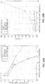
- Example 10 four different preforms were tested to determine the effect of a sacrificial tip on drawing bulb mass and drip time.
- the four preforms were a 90 mm primary rod with no sacrificial tip, a 90 mm primary rod with a solid 30 mm with an outside diameter of 40 mm, a 90 mm primary rod with a solid 60 mm stub with an outside diameter of 60 mm, and a 90 mm primary rod with a hollow cylindrical sacrificial tip with a length of 30 mm, an outside diameter of 90 mm, and an inside diameter of 60 mm.
- Each preform was tested with the preform bottom at various heats relative to the center of the heating element. As can be seen from FIG.
- the mass of the drawing bulb decreases.
- the mass of the preform glass drop is goes to essentially zero as the preform bottom is moved at least 20 cm above the center of the furnace, indicating essentially no material waste.
- the preform with the hollow cylinder sacrificial tip also demonstrated substantially reduced drip times, indicating a faster and more efficient draw process.
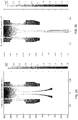
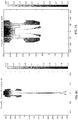
- Example 9 the impact of the sacrificial tip on the cladding-to-core ratio of the resulting drawn fiber was measured by comparing a 90 mm preform with no sacrificial tip ( FIGS. 11A-11C ) to a 90 mm preform with a hollow cylindrical sacrificial tip with a length of 30 mm, an outside diameter of 90 mm, and an inside diameter of 60 mm ( FIGS. 12A-12C ).
- FIGS 11A and 12A depict the position, geometry, and temperature of the respective preforms after a tapered tube has formed at the bottom of the preform.
- FIGS. 11B and 12B depict the respective preforms at the intersection of the tapered tube and the preform body, specifically detailing the presence of the core rod within the preform.
- FIGS. 11C and 12C depict the cladding-to-core ratio along the length of the preform.
- the core rod is pulled down into a drawing bulb, resulting in large variations in cladding-to-core ratio.
- Such a distorted cladding-to-core ratio results in unusable fiber and the draw must continue until the cladding-to-core ratio stabilizes, resulting in material waste.
- FIGS. 11A-11C depict the core rod is pulled down into a drawing bulb, resulting in large variations in cladding-to-core ratio.
- Such a distorted cladding-to-core ratio results in unusable fiber and the draw must continue until the cladding-to-core ratio stabilizes, resulting in material waste.
- FIGS. 11C and 12C depict the cladding-to-core ratio along the length of the preform.
- the addition of the hollow cylinder sacrificial tip forms a thin, tapered tube that includes essentially no material of the core rod and reduces the cladding-to-core ratio distortion in the neckdown and drip compared to the preform with no sacrificial tip.
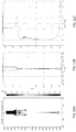
- Example 10 the impact on the position of the preform within the furnace on the cladding-to-core ratio of the resulting drawn fiber was measured by comparing the result of a 90 mm preform with a hollow cylinder sacrificial tip with a length of 30 mm, an outside diameter of 90 mm, and an inside diameter of 60 mm at various furnace positions, specifically at an optimized position ( FIGS. 13A-13C ), 10 mm below the optimized position ( FIGS. 14A-14C ), and 10 mm above the optimized position ( FIGS. 15A-15C ).
- FIGS 13A , 14A , and 15A depict the position, geometry, and temperature of the respective preforms after a tapered tube has formed at the bottom of the preform.
- FIGS. 13B , 14B , and 15B depict the respective preforms at the intersection of the tapered tube and the preform body, specifically detailing the presence of the core rod within the preform.
- the preform bottom forms a tip with minimum glass waste, and a minimum portion of glass with an altered cladding-to-core ratio.
- FIGS. 14A-14C when the preform is positioned too low, the drip from the sacrificial tip is much shorter and a drip of preform glass also forms.
Landscapes
- Engineering & Computer Science (AREA)
- Chemical & Material Sciences (AREA)
- Life Sciences & Earth Sciences (AREA)
- General Life Sciences & Earth Sciences (AREA)
- Geochemistry & Mineralogy (AREA)
- Manufacturing & Machinery (AREA)
- Materials Engineering (AREA)
- Organic Chemistry (AREA)
- Manufacture, Treatment Of Glass Fibers (AREA)
- Glass Melting And Manufacturing (AREA)
- Re-Forming, After-Treatment, Cutting And Transporting Of Glass Products (AREA)
- Glass Compositions (AREA)
Claims (10)
- Procédé de formation d'un composant optique en verre, le procédé comprenant :le positionnement d'une ébauche de verre dans un fourneau, dans lequel l'ébauche de verre inclut une tige primaire non allongée ayant un diamètre extérieur constant et un fond carré, et une pointe sacrificielle ayant une première extrémité fixée au fond de la tige primaire non allongée, une seconde extrémité opposée à la première extrémité, et une région intérieure creuse s'étendant de la première extrémité à la seconde extrémité, dans lequel la pointe sacrificielle présente une section transversale circulaire et la première extrémité de la pointe sacrificielle a un diamètre extérieur égal au diamètre extérieur de la tige primaire non allongée ; etle chauffage de l'ébauche de verre dans le fourneau pour ramollir la pointe sacrificielle, moyennant quoi une goutte se forme au niveau d'une extrémité inférieure de l'ébauche et la goutte descend et allonge la tige primaire non allongée pour former une tige primaire allongée.
- Procédé selon la revendication 1, dans lequel la tige primaire non allongée et la pointe sacrificielle sont toutes deux composées de verre de silice, et le verre de silice de la tige primaire non allongée est d'une qualité supérieure à celle du verre de silice de la pointe sacrificielle, dans lequel de préférence la pointe sacrificielle est soudée à la tige primaire.
- Procédé selon l'une quelconque des revendications 1 à 2, dans lequel la pointe sacrificielle a un diamètre extérieur constant égal au diamètre extérieur de la tige primaire non allongée.
- Procédé selon l'une quelconque des revendications 1-3, dans lequel la région intérieure creuse a un diamètre intérieur allant d'environ 50 % à environ 80 % du diamètre extérieur de la pointe sacrificielle.
- Procédé selon l'une quelconque des revendications 1-4, dans lequel la pointe sacrificielle a une longueur d'environ 10 mm à environ 60 mm, a de préférence une longueur d'environ 20 mm à environ 50 mm, et a de manière préférée entre toutes une longueur d'environ 25 mm à environ 35 mm.
- Procédé selon l'une quelconque des revendications 1-5, comprenant en outre le préchauffage de l'ébauche de verre à une hauteur au-dessus du centre du fourneau avant le positionnement de l'ébauche de verre dans le fourneau au niveau d'un emplacement optimisé à l'intérieur du fourneau.
- Procédé selon la revendication 6, dans lequel le préchauffage de l'ébauche de verre à l'extérieur du fourneau comprend :le chauffage du fourneau à une faible puissance ;le positionnement de l'ébauche de verre au niveau d'un premier emplacement au-dessus du centre du fourneau à une faible puissance pendant une première période ;l'augmentation de la puissance du fourneau à une puissance d'exploitation supérieure du fourneau ; etl'abaissement de l'ébauche dans le fourneau à un emplacement de suspension optimisé au-dessus du centre du fourneau.
- Procédé selon la revendication 7, dans lequel l'abaissement de l'ébauche dans le four vers l'emplacement de suspension optimisé comprend :l'abaissement de l'ébauche dans le four du premier emplacement à un second emplacement au-dessus de l'emplacement de suspension optimisé ;le maintien de l'ébauche au niveau du second emplacement pendant une période donnée ; etl'abaissement de l'ébauche dans le four du second emplacement à l'emplacement de suspension optimisé.
- Procédé selon l'une quelconque des revendications 1-8, dans lequel la goutte formée au niveau d'une extrémité de fond de l'ébauche inclut sensiblement seulement un matériau provenant de la pointe sacrificielle et aucun matériau provenant de la tige primaire non allongée,
dans lequel de préférence la tige primaire non allongée inclut un ensemble ébauche tige-dans-cylindre dans un état non plié avec une tige de noyau entourée par un ou plusieurs cylindres sur-plaqués ou dans lequel la tige primaire non allongée inclut une tige de noyau entourée par une ou plusieurs couches de placage externes,
moyennant quoi de préférence la goutte descendant sur et allongeant la tige primaire non allongée comprend la traction sur une partie extérieure de la couche de placage sans traction sur la tige de noyau. - Procédé selon l'une quelconque des revendications 1-9, dans lequel la tige primaire allongée a un rapport placage/noyau qui est sensiblement le même que le rapport placage/noyau de la tige primaire non allongée.
Priority Applications (1)
| Application Number | Priority Date | Filing Date | Title |
|---|---|---|---|
| EP20158240.0A EP3686167B1 (fr) | 2016-05-03 | 2017-04-26 | Preforme pour produire un composant optique en verre |
Applications Claiming Priority (1)
| Application Number | Priority Date | Filing Date | Title |
|---|---|---|---|
| US201662330995P | 2016-05-03 | 2016-05-03 |
Related Child Applications (2)
| Application Number | Title | Priority Date | Filing Date |
|---|---|---|---|
| EP20158240.0A Division-Into EP3686167B1 (fr) | 2016-05-03 | 2017-04-26 | Preforme pour produire un composant optique en verre |
| EP20158240.0A Division EP3686167B1 (fr) | 2016-05-03 | 2017-04-26 | Preforme pour produire un composant optique en verre |
Publications (2)
| Publication Number | Publication Date |
|---|---|
| EP3243804A1 EP3243804A1 (fr) | 2017-11-15 |
| EP3243804B1 true EP3243804B1 (fr) | 2020-07-15 |
Family
ID=58632867
Family Applications (2)
| Application Number | Title | Priority Date | Filing Date |
|---|---|---|---|
| EP17168145.5A Active EP3243804B1 (fr) | 2016-05-03 | 2017-04-26 | Procédé d'allongement pour produire un composant optique en verre |
| EP20158240.0A Active EP3686167B1 (fr) | 2016-05-03 | 2017-04-26 | Preforme pour produire un composant optique en verre |
Family Applications After (1)
| Application Number | Title | Priority Date | Filing Date |
|---|---|---|---|
| EP20158240.0A Active EP3686167B1 (fr) | 2016-05-03 | 2017-04-26 | Preforme pour produire un composant optique en verre |
Country Status (5)
| Country | Link |
|---|---|
| US (2) | US11618708B2 (fr) |
| EP (2) | EP3243804B1 (fr) |
| JP (1) | JP7090402B2 (fr) |
| KR (1) | KR102425328B1 (fr) |
| CN (1) | CN107337345B (fr) |
Families Citing this family (6)
| Publication number | Priority date | Publication date | Assignee | Title |
|---|---|---|---|---|
| US11405107B2 (en) | 2016-11-22 | 2022-08-02 | Heraeus Quartz North America Llc | Upward collapse process and apparatus for making glass preforms |
| EP3636607B1 (fr) * | 2018-10-09 | 2021-01-13 | Heraeus Quarzglas GmbH & Co. KG | Procédé de fabrication d'un tube capillaire |
| EP3683195B1 (fr) | 2019-01-15 | 2024-11-27 | Heraeus Quartz North America LLC | Procédé automatique de mise en forme de la pointe de préformes de verre de grand diamètre extérieur |
| CN112159094A (zh) * | 2020-05-14 | 2021-01-01 | 江苏永鼎光纤科技有限公司 | 一种光纤预制棒锥头自动处理方法 |
| US20240174546A1 (en) * | 2021-07-27 | 2024-05-30 | Dstar Communications, Inc. | Microgravity crucible-controlled manufacturing |
| WO2024004512A1 (fr) * | 2022-06-27 | 2024-01-04 | 住友電気工業株式会社 | Procédé de production de matériau de base de fibre optique |
Family Cites Families (37)
| Publication number | Priority date | Publication date | Assignee | Title |
|---|---|---|---|---|
| JPS596264B2 (ja) * | 1977-04-04 | 1984-02-09 | 株式会社フジクラ | 光フアイバの紡糸方法 |
| JPS5924741B2 (ja) | 1979-07-17 | 1984-06-12 | 日本電信電話株式会社 | 光フアイバ母材の製造方法 |
| JPS61251536A (ja) | 1985-04-26 | 1986-11-08 | Fujitsu Ltd | 光フアイバの製造方法 |
| JPS63170235A (ja) * | 1987-01-09 | 1988-07-14 | Sumitomo Electric Ind Ltd | 光フアイバ用線引母材の製造方法 |
| EP0598349B1 (fr) * | 1992-11-19 | 1998-07-29 | Shin-Etsu Quartz Products Co., Ltd. | Procédé pour la fabrication d'un tube en verre de quartz à grande dimension, d'une préforme et d'une fibre optique |
| JPH07330362A (ja) | 1994-06-06 | 1995-12-19 | Fujikura Ltd | ガラスファイバ紡糸用母材先端の加工方法およびその装置 |
| JPH08310825A (ja) | 1995-05-15 | 1996-11-26 | Fujikura Ltd | 光ファイバ母材の加工方法 |
| JP3711662B2 (ja) * | 1996-10-24 | 2005-11-02 | 住友電気工業株式会社 | 光ファイバ線引方法及び光ファイバ線引炉 |
| JP3714571B2 (ja) * | 1996-12-24 | 2005-11-09 | 信越石英株式会社 | 光ファイバ母材と該母材を用いた光ファイバの製造方法 |
| US6279353B1 (en) * | 1997-03-25 | 2001-08-28 | The Furukawa Electric Co., Ltd. | Electric furnace extension method and extension apparatus for optical fiber glass preform |
| US6532776B1 (en) | 1997-06-27 | 2003-03-18 | Shin-Etsu Chemical Co., Ltd. | Method and apparatus for fusing an optical fiber preform |
| DE19914507A1 (de) | 1999-03-30 | 2000-10-05 | Siecor Fertigungsgesellschaft | Vorrichtung zur Wärmebehandlung eines Objektes |
| JP2000327358A (ja) * | 1999-05-11 | 2000-11-28 | Shin Etsu Chem Co Ltd | 光ファイバ母材の接続加工方法 |
| WO2000076926A1 (fr) * | 1999-06-14 | 2000-12-21 | The Furukawa Electric Co., Ltd. | Procede et dispositif de chauffage/usinage de l'extremite du materiau de base d'une fibre optique |
| JP2001039721A (ja) * | 1999-07-29 | 2001-02-13 | Shin Etsu Chem Co Ltd | 光ファイバプリフォームの熱処理方法 |
| NL1014374C2 (nl) | 2000-02-14 | 2001-08-15 | Draka Fibre Technology Bv | Staafvormig vormdeel voor het hieruit vervaardigen van een optische vezel, werkwijze voor het vervaardigen van een dergelijk staafvormig vormdeel alsmede werkwijze voor het vervaardigen van een optische vezel onder toepassing van een dergelijk staafvormig vormdeel. |
| JP2002080238A (ja) | 2000-09-06 | 2002-03-19 | Sumitomo Electric Ind Ltd | 光ファイバ用母材及びその成型方法 |
| CN1227174C (zh) * | 2000-09-29 | 2005-11-16 | 康宁股份有限公司 | 用于使光纤预制件的拉制端再成形的方法和装置 |
| US6779363B1 (en) * | 2000-09-29 | 2004-08-24 | Corning Incorporated | Method for pregobbing an optical fiber preform and system producing optical fiber therefrom |
| WO2002028789A1 (fr) | 2000-09-29 | 2002-04-11 | Corning Incorporated | Procede et dispositif de reformage de l'extremite de depouille d'une preforme de fibres optiques |
| WO2002096816A1 (fr) | 2001-05-30 | 2002-12-05 | Pirelli & C. S.P.A. | Procede de fabrication de preformes de fibres optiques en verre et fibres optiques |
| EP1279646B1 (fr) * | 2001-07-26 | 2006-12-13 | Sumitomo Electric Industries, Ltd. | Procédé et appareil pour la fabrication d'une préforme en verre pour fibre optiques |
| US8091387B2 (en) * | 2003-03-19 | 2012-01-10 | Hoya Corporation | Method of manufacturing glass articles, method of manufacturing glass gobs, and method of manufacturing optical elements |
| DE10333059A1 (de) | 2003-07-18 | 2005-02-17 | Heraeus Tenevo Ag | Verfahren zur Herstellung eines optischen Bauteils aus Quarzglas sowie Hohlzylinder aus Quarzglas zur Durchführung des Verfahrens |
| JP2005145796A (ja) * | 2003-11-19 | 2005-06-09 | Shin Etsu Chem Co Ltd | 光ファイバ母材及びその接続加工方法並びに装置 |
| JP4106038B2 (ja) * | 2004-03-03 | 2008-06-25 | 正隆 中沢 | フォトニッククリスタル光ファイバの製造方法 |
| DE102004039645B3 (de) * | 2004-08-14 | 2006-01-05 | Heraeus Tenevo Ag | Verfahren zur Herstellung eines optischen Bauteils aus Quarzglas sowie zur Durchführung des Verfahrens geeignetes Vorprodukt |
| JP4453674B2 (ja) * | 2006-03-24 | 2010-04-21 | 住友電気工業株式会社 | 光ファイバ母材製造方法 |
| JP4691008B2 (ja) * | 2006-12-11 | 2011-06-01 | 古河電気工業株式会社 | 光ファイバの製造方法 |
| JP5512808B2 (ja) * | 2010-05-21 | 2014-06-04 | 株式会社フジクラ | 光ファイバ素線の製造方法 |
| EP2949331A1 (fr) | 2012-10-17 | 2015-12-02 | Methylation Sciences International SRL | Compositions comprenant de la s-adénosylméthionine et un ester d'acide gallique |
| CN103739193B (zh) * | 2013-12-16 | 2016-01-06 | 江苏亨通光电股份有限公司 | 一种光纤预制棒锥头的生产方法 |
| JP6426478B2 (ja) | 2014-01-31 | 2018-11-21 | 信越化学工業株式会社 | ガラスロッドの加工方法および加工装置 |
| JP6303747B2 (ja) * | 2014-04-11 | 2018-04-04 | 住友電気工業株式会社 | 接続構造および光ファイバの製造方法 |
| KR101978103B1 (ko) * | 2014-08-13 | 2019-05-13 | 헤래우스 테네보 엘엘씨 | 석영 유리 제품 및 석영 유리 광학 소자의 형성 방법 |
| JP6302833B2 (ja) | 2014-12-26 | 2018-03-28 | 信越化学工業株式会社 | ガラスロッドの絞り加工方法 |
| JP7134462B2 (ja) | 2018-03-28 | 2022-09-12 | 国立大学法人 大分大学 | 胚の評価方法 |
-
2017
- 2017-04-26 EP EP17168145.5A patent/EP3243804B1/fr active Active
- 2017-04-26 KR KR1020170053304A patent/KR102425328B1/ko active Active
- 2017-04-26 JP JP2017087315A patent/JP7090402B2/ja active Active
- 2017-04-26 US US15/497,316 patent/US11618708B2/en active Active
- 2017-04-26 CN CN201710285034.3A patent/CN107337345B/zh active Active
- 2017-04-26 EP EP20158240.0A patent/EP3686167B1/fr active Active
-
2021
- 2021-01-19 US US17/152,518 patent/US11840472B2/en active Active
Non-Patent Citations (1)
| Title |
|---|
| None * |
Also Published As
| Publication number | Publication date |
|---|---|
| US11840472B2 (en) | 2023-12-12 |
| EP3686167A1 (fr) | 2020-07-29 |
| KR102425328B1 (ko) | 2022-07-25 |
| US20210130221A1 (en) | 2021-05-06 |
| JP2017206432A (ja) | 2017-11-24 |
| CN107337345A (zh) | 2017-11-10 |
| KR20170124965A (ko) | 2017-11-13 |
| JP7090402B2 (ja) | 2022-06-24 |
| EP3243804A1 (fr) | 2017-11-15 |
| CN107337345B (zh) | 2022-07-05 |
| EP3686167B1 (fr) | 2024-09-25 |
| US11618708B2 (en) | 2023-04-04 |
| US20170320768A1 (en) | 2017-11-09 |
Similar Documents
| Publication | Publication Date | Title |
|---|---|---|
| US11840472B2 (en) | Elongation method and preform for producing an optical glass component | |
| JP6824156B2 (ja) | 石英ガラス製品及び石英ガラス光学部材の形成方法 | |
| PT1740510E (pt) | Método de fabrico de uma fibra óptica e pré-forma para fabricar uma fibra óptica | |
| CN106030358A (zh) | 光子晶体光纤、特别地用于ir波长范围的单模光纤以及用于其生产的处理 | |
| EP1426339A1 (fr) | Préforme à barre-en-tube pour des fibres optiques et procédé d'étirage de la préforme | |
| JP2002097033A (ja) | 焼結中にオーバークラッディングを伴う光ファイバの製造方法 | |
| US20040071421A1 (en) | Silica-based optical fibers and multi-pass sintering | |
| US20050034484A1 (en) | Preparing preforms for fibre fabrication | |
| US11130702B2 (en) | Optical fiber manufacturing method | |
| JP7830828B2 (ja) | マルチコアファイバを製造するための方法及び半製品 | |
| JP6824233B2 (ja) | 石英ガラス製品及び石英ガラス光学部材の形成方法 | |
| US10464837B2 (en) | Method for inserting a core rod into an outer cladding tube with spacer | |
| KR100326323B1 (ko) | 광섬유 모재의 제조방법 | |
| RU2552590C1 (ru) | Фотонно-кристаллическое халькогенидное волокно и способ его изготовления | |
| EP1203755B1 (fr) | Procede de fabrication de matiere premiere pour fibre optique | |
| EP4545498A1 (fr) | Procédé de fabrication d'une préforme de fibre optique, et préforme de fibre optique | |
| JP2021006505A (ja) | 石英ガラス製品及び石英ガラス光学部材の形成方法 | |
| JPH0710580A (ja) | 光ファイバ母材の製造方法 | |
| JP3788503B2 (ja) | 光ファイバ用ガラス母材の製造方法および製造装置 | |
| Kim et al. | COMPUTATIONAL STUDY OF GLASS FIBER DRAWING PROCESS IN A DRAW FURNACE OF OPTICAL FIBER MASS MANUFACTURING SYSTEM | |
| JPWO2024004512A5 (fr) | ||
| AU2002318992A1 (en) | Preparing preforms for fibre fabrication |
Legal Events
| Date | Code | Title | Description |
|---|---|---|---|
| PUAI | Public reference made under article 153(3) epc to a published international application that has entered the european phase |
Free format text: ORIGINAL CODE: 0009012 |
|
| STAA | Information on the status of an ep patent application or granted ep patent |
Free format text: STATUS: THE APPLICATION HAS BEEN PUBLISHED |
|
| AK | Designated contracting states |
Kind code of ref document: A1 Designated state(s): AL AT BE BG CH CY CZ DE DK EE ES FI FR GB GR HR HU IE IS IT LI LT LU LV MC MK MT NL NO PL PT RO RS SE SI SK SM TR |
|
| AX | Request for extension of the european patent |
Extension state: BA ME |
|
| STAA | Information on the status of an ep patent application or granted ep patent |
Free format text: STATUS: REQUEST FOR EXAMINATION WAS MADE |
|
| STAA | Information on the status of an ep patent application or granted ep patent |
Free format text: STATUS: EXAMINATION IS IN PROGRESS |
|
| 17P | Request for examination filed |
Effective date: 20180515 |
|
| RBV | Designated contracting states (corrected) |
Designated state(s): AL AT BE BG CH CY CZ DE DK EE ES FI FR GB GR HR HU IE IS IT LI LT LU LV MC MK MT NL NO PL PT RO RS SE SI SK SM TR |
|
| 17Q | First examination report despatched |
Effective date: 20180608 |
|
| GRAP | Despatch of communication of intention to grant a patent |
Free format text: ORIGINAL CODE: EPIDOSNIGR1 |
|
| STAA | Information on the status of an ep patent application or granted ep patent |
Free format text: STATUS: GRANT OF PATENT IS INTENDED |
|
| RAP1 | Party data changed (applicant data changed or rights of an application transferred) |
Owner name: HERAEUS QUARTZ NORTH AMERICA LLC |
|
| INTG | Intention to grant announced |
Effective date: 20200205 |
|
| GRAS | Grant fee paid |
Free format text: ORIGINAL CODE: EPIDOSNIGR3 |
|
| GRAA | (expected) grant |
Free format text: ORIGINAL CODE: 0009210 |
|
| STAA | Information on the status of an ep patent application or granted ep patent |
Free format text: STATUS: THE PATENT HAS BEEN GRANTED |
|
| AK | Designated contracting states |
Kind code of ref document: B1 Designated state(s): AL AT BE BG CH CY CZ DE DK EE ES FI FR GB GR HR HU IE IS IT LI LT LU LV MC MK MT NL NO PL PT RO RS SE SI SK SM TR |
|
| REG | Reference to a national code |
Ref country code: CH Ref legal event code: EP Ref country code: GB Ref legal event code: FG4D |
|
| REG | Reference to a national code |
Ref country code: IE Ref legal event code: FG4D |
|
| REG | Reference to a national code |
Ref country code: DE Ref legal event code: R096 Ref document number: 602017019660 Country of ref document: DE |
|
| REG | Reference to a national code |
Ref country code: AT Ref legal event code: REF Ref document number: 1290854 Country of ref document: AT Kind code of ref document: T Effective date: 20200815 |
|
| REG | Reference to a national code |
Ref country code: LT Ref legal event code: MG4D |
|
| REG | Reference to a national code |
Ref country code: AT Ref legal event code: MK05 Ref document number: 1290854 Country of ref document: AT Kind code of ref document: T Effective date: 20200715 |
|
| REG | Reference to a national code |
Ref country code: NL Ref legal event code: MP Effective date: 20200715 |
|
| PG25 | Lapsed in a contracting state [announced via postgrant information from national office to epo] |
Ref country code: FI Free format text: LAPSE BECAUSE OF FAILURE TO SUBMIT A TRANSLATION OF THE DESCRIPTION OR TO PAY THE FEE WITHIN THE PRESCRIBED TIME-LIMIT Effective date: 20200715 Ref country code: HR Free format text: LAPSE BECAUSE OF FAILURE TO SUBMIT A TRANSLATION OF THE DESCRIPTION OR TO PAY THE FEE WITHIN THE PRESCRIBED TIME-LIMIT Effective date: 20200715 Ref country code: LT Free format text: LAPSE BECAUSE OF FAILURE TO SUBMIT A TRANSLATION OF THE DESCRIPTION OR TO PAY THE FEE WITHIN THE PRESCRIBED TIME-LIMIT Effective date: 20200715 Ref country code: NO Free format text: LAPSE BECAUSE OF FAILURE TO SUBMIT A TRANSLATION OF THE DESCRIPTION OR TO PAY THE FEE WITHIN THE PRESCRIBED TIME-LIMIT Effective date: 20201015 Ref country code: ES Free format text: LAPSE BECAUSE OF FAILURE TO SUBMIT A TRANSLATION OF THE DESCRIPTION OR TO PAY THE FEE WITHIN THE PRESCRIBED TIME-LIMIT Effective date: 20200715 Ref country code: GR Free format text: LAPSE BECAUSE OF FAILURE TO SUBMIT A TRANSLATION OF THE DESCRIPTION OR TO PAY THE FEE WITHIN THE PRESCRIBED TIME-LIMIT Effective date: 20201016 Ref country code: SE Free format text: LAPSE BECAUSE OF FAILURE TO SUBMIT A TRANSLATION OF THE DESCRIPTION OR TO PAY THE FEE WITHIN THE PRESCRIBED TIME-LIMIT Effective date: 20200715 Ref country code: BG Free format text: LAPSE BECAUSE OF FAILURE TO SUBMIT A TRANSLATION OF THE DESCRIPTION OR TO PAY THE FEE WITHIN THE PRESCRIBED TIME-LIMIT Effective date: 20201015 Ref country code: PT Free format text: LAPSE BECAUSE OF FAILURE TO SUBMIT A TRANSLATION OF THE DESCRIPTION OR TO PAY THE FEE WITHIN THE PRESCRIBED TIME-LIMIT Effective date: 20201116 Ref country code: AT Free format text: LAPSE BECAUSE OF FAILURE TO SUBMIT A TRANSLATION OF THE DESCRIPTION OR TO PAY THE FEE WITHIN THE PRESCRIBED TIME-LIMIT Effective date: 20200715 |
|
| PG25 | Lapsed in a contracting state [announced via postgrant information from national office to epo] |
Ref country code: RS Free format text: LAPSE BECAUSE OF FAILURE TO SUBMIT A TRANSLATION OF THE DESCRIPTION OR TO PAY THE FEE WITHIN THE PRESCRIBED TIME-LIMIT Effective date: 20200715 Ref country code: PL Free format text: LAPSE BECAUSE OF FAILURE TO SUBMIT A TRANSLATION OF THE DESCRIPTION OR TO PAY THE FEE WITHIN THE PRESCRIBED TIME-LIMIT Effective date: 20200715 Ref country code: LV Free format text: LAPSE BECAUSE OF FAILURE TO SUBMIT A TRANSLATION OF THE DESCRIPTION OR TO PAY THE FEE WITHIN THE PRESCRIBED TIME-LIMIT Effective date: 20200715 Ref country code: IS Free format text: LAPSE BECAUSE OF FAILURE TO SUBMIT A TRANSLATION OF THE DESCRIPTION OR TO PAY THE FEE WITHIN THE PRESCRIBED TIME-LIMIT Effective date: 20201115 |
|
| PG25 | Lapsed in a contracting state [announced via postgrant information from national office to epo] |
Ref country code: NL Free format text: LAPSE BECAUSE OF FAILURE TO SUBMIT A TRANSLATION OF THE DESCRIPTION OR TO PAY THE FEE WITHIN THE PRESCRIBED TIME-LIMIT Effective date: 20200715 |
|
| REG | Reference to a national code |
Ref country code: DE Ref legal event code: R097 Ref document number: 602017019660 Country of ref document: DE |
|
| PG25 | Lapsed in a contracting state [announced via postgrant information from national office to epo] |
Ref country code: RO Free format text: LAPSE BECAUSE OF FAILURE TO SUBMIT A TRANSLATION OF THE DESCRIPTION OR TO PAY THE FEE WITHIN THE PRESCRIBED TIME-LIMIT Effective date: 20200715 Ref country code: DK Free format text: LAPSE BECAUSE OF FAILURE TO SUBMIT A TRANSLATION OF THE DESCRIPTION OR TO PAY THE FEE WITHIN THE PRESCRIBED TIME-LIMIT Effective date: 20200715 Ref country code: CZ Free format text: LAPSE BECAUSE OF FAILURE TO SUBMIT A TRANSLATION OF THE DESCRIPTION OR TO PAY THE FEE WITHIN THE PRESCRIBED TIME-LIMIT Effective date: 20200715 Ref country code: EE Free format text: LAPSE BECAUSE OF FAILURE TO SUBMIT A TRANSLATION OF THE DESCRIPTION OR TO PAY THE FEE WITHIN THE PRESCRIBED TIME-LIMIT Effective date: 20200715 Ref country code: SM Free format text: LAPSE BECAUSE OF FAILURE TO SUBMIT A TRANSLATION OF THE DESCRIPTION OR TO PAY THE FEE WITHIN THE PRESCRIBED TIME-LIMIT Effective date: 20200715 |
|
| PLBE | No opposition filed within time limit |
Free format text: ORIGINAL CODE: 0009261 |
|
| STAA | Information on the status of an ep patent application or granted ep patent |
Free format text: STATUS: NO OPPOSITION FILED WITHIN TIME LIMIT |
|
| PG25 | Lapsed in a contracting state [announced via postgrant information from national office to epo] |
Ref country code: AL Free format text: LAPSE BECAUSE OF FAILURE TO SUBMIT A TRANSLATION OF THE DESCRIPTION OR TO PAY THE FEE WITHIN THE PRESCRIBED TIME-LIMIT Effective date: 20200715 |
|
| 26N | No opposition filed |
Effective date: 20210416 |
|
| PG25 | Lapsed in a contracting state [announced via postgrant information from national office to epo] |
Ref country code: SK Free format text: LAPSE BECAUSE OF FAILURE TO SUBMIT A TRANSLATION OF THE DESCRIPTION OR TO PAY THE FEE WITHIN THE PRESCRIBED TIME-LIMIT Effective date: 20200715 |
|
| PG25 | Lapsed in a contracting state [announced via postgrant information from national office to epo] |
Ref country code: SI Free format text: LAPSE BECAUSE OF FAILURE TO SUBMIT A TRANSLATION OF THE DESCRIPTION OR TO PAY THE FEE WITHIN THE PRESCRIBED TIME-LIMIT Effective date: 20200715 |
|
| PG25 | Lapsed in a contracting state [announced via postgrant information from national office to epo] |
Ref country code: MC Free format text: LAPSE BECAUSE OF FAILURE TO SUBMIT A TRANSLATION OF THE DESCRIPTION OR TO PAY THE FEE WITHIN THE PRESCRIBED TIME-LIMIT Effective date: 20200715 |
|
| GBPC | Gb: european patent ceased through non-payment of renewal fee |
Effective date: 20210426 |
|
| PG25 | Lapsed in a contracting state [announced via postgrant information from national office to epo] |
Ref country code: LU Free format text: LAPSE BECAUSE OF NON-PAYMENT OF DUE FEES Effective date: 20210426 |
|
| REG | Reference to a national code |
Ref country code: BE Ref legal event code: MM Effective date: 20210430 |
|
| PG25 | Lapsed in a contracting state [announced via postgrant information from national office to epo] |
Ref country code: FR Free format text: LAPSE BECAUSE OF NON-PAYMENT OF DUE FEES Effective date: 20210430 Ref country code: GB Free format text: LAPSE BECAUSE OF NON-PAYMENT OF DUE FEES Effective date: 20210426 Ref country code: CH Free format text: LAPSE BECAUSE OF NON-PAYMENT OF DUE FEES Effective date: 20210430 Ref country code: LI Free format text: LAPSE BECAUSE OF NON-PAYMENT OF DUE FEES Effective date: 20210430 |
|
| PG25 | Lapsed in a contracting state [announced via postgrant information from national office to epo] |
Ref country code: IE Free format text: LAPSE BECAUSE OF NON-PAYMENT OF DUE FEES Effective date: 20210426 |
|
| PG25 | Lapsed in a contracting state [announced via postgrant information from national office to epo] |
Ref country code: IS Free format text: LAPSE BECAUSE OF FAILURE TO SUBMIT A TRANSLATION OF THE DESCRIPTION OR TO PAY THE FEE WITHIN THE PRESCRIBED TIME-LIMIT Effective date: 20201115 |
|
| PG25 | Lapsed in a contracting state [announced via postgrant information from national office to epo] |
Ref country code: BE Free format text: LAPSE BECAUSE OF NON-PAYMENT OF DUE FEES Effective date: 20210430 |
|
| PG25 | Lapsed in a contracting state [announced via postgrant information from national office to epo] |
Ref country code: HU Free format text: LAPSE BECAUSE OF FAILURE TO SUBMIT A TRANSLATION OF THE DESCRIPTION OR TO PAY THE FEE WITHIN THE PRESCRIBED TIME-LIMIT; INVALID AB INITIO Effective date: 20170426 |
|
| PG25 | Lapsed in a contracting state [announced via postgrant information from national office to epo] |
Ref country code: CY Free format text: LAPSE BECAUSE OF FAILURE TO SUBMIT A TRANSLATION OF THE DESCRIPTION OR TO PAY THE FEE WITHIN THE PRESCRIBED TIME-LIMIT Effective date: 20200715 |
|
| PG25 | Lapsed in a contracting state [announced via postgrant information from national office to epo] |
Ref country code: MK Free format text: LAPSE BECAUSE OF FAILURE TO SUBMIT A TRANSLATION OF THE DESCRIPTION OR TO PAY THE FEE WITHIN THE PRESCRIBED TIME-LIMIT Effective date: 20200715 |
|
| PG25 | Lapsed in a contracting state [announced via postgrant information from national office to epo] |
Ref country code: TR Free format text: LAPSE BECAUSE OF FAILURE TO SUBMIT A TRANSLATION OF THE DESCRIPTION OR TO PAY THE FEE WITHIN THE PRESCRIBED TIME-LIMIT Effective date: 20200715 |
|
| PG25 | Lapsed in a contracting state [announced via postgrant information from national office to epo] |
Ref country code: MT Free format text: LAPSE BECAUSE OF FAILURE TO SUBMIT A TRANSLATION OF THE DESCRIPTION OR TO PAY THE FEE WITHIN THE PRESCRIBED TIME-LIMIT Effective date: 20200715 |
|
| PGFP | Annual fee paid to national office [announced via postgrant information from national office to epo] |
Ref country code: DE Payment date: 20250422 Year of fee payment: 9 |
|
| PGFP | Annual fee paid to national office [announced via postgrant information from national office to epo] |
Ref country code: IT Payment date: 20250424 Year of fee payment: 9 |