EP3243976A1 - Plattenspleissverbinder für lineare deckenplatten - Google Patents
Plattenspleissverbinder für lineare deckenplatten Download PDFInfo
- Publication number
- EP3243976A1 EP3243976A1 EP17169788.1A EP17169788A EP3243976A1 EP 3243976 A1 EP3243976 A1 EP 3243976A1 EP 17169788 A EP17169788 A EP 17169788A EP 3243976 A1 EP3243976 A1 EP 3243976A1
- Authority
- EP
- European Patent Office
- Prior art keywords
- panel
- connector
- base portion
- linear
- region
- Prior art date
- Legal status (The legal status is an assumption and is not a legal conclusion. Google has not performed a legal analysis and makes no representation as to the accuracy of the status listed.)
- Granted
Links
Images


Classifications
-
- E—FIXED CONSTRUCTIONS
- E04—BUILDING
- E04F—FINISHING WORK ON BUILDINGS, e.g. STAIRS, FLOORS
- E04F13/00—Coverings or linings, e.g. for walls or ceilings
- E04F13/07—Coverings or linings, e.g. for walls or ceilings composed of covering or lining elements; Sub-structures therefor; Fastening means therefor
- E04F13/08—Coverings or linings, e.g. for walls or ceilings composed of covering or lining elements; Sub-structures therefor; Fastening means therefor composed of a plurality of similar covering or lining elements
- E04F13/12—Coverings or linings, e.g. for walls or ceilings composed of covering or lining elements; Sub-structures therefor; Fastening means therefor composed of a plurality of similar covering or lining elements of metal or with an outer layer of metal or enameled metal
-
- F—MECHANICAL ENGINEERING; LIGHTING; HEATING; WEAPONS; BLASTING
- F16—ENGINEERING ELEMENTS AND UNITS; GENERAL MEASURES FOR PRODUCING AND MAINTAINING EFFECTIVE FUNCTIONING OF MACHINES OR INSTALLATIONS; THERMAL INSULATION IN GENERAL
- F16B—DEVICES FOR FASTENING OR SECURING CONSTRUCTIONAL ELEMENTS OR MACHINE PARTS TOGETHER, e.g. NAILS, BOLTS, CIRCLIPS, CLAMPS, CLIPS OR WEDGES; JOINTS OR JOINTING
- F16B5/00—Joining sheets or plates, e.g. panels, to one another or to strips or bars parallel to them
- F16B5/06—Joining sheets or plates, e.g. panels, to one another or to strips or bars parallel to them by means of clamps or clips
- F16B5/0607—Joining sheets or plates, e.g. panels, to one another or to strips or bars parallel to them by means of clamps or clips joining sheets or plates to each other
- F16B5/0621—Joining sheets or plates, e.g. panels, to one another or to strips or bars parallel to them by means of clamps or clips joining sheets or plates to each other in parallel relationship
- F16B5/0642—Joining sheets or plates, e.g. panels, to one another or to strips or bars parallel to them by means of clamps or clips joining sheets or plates to each other in parallel relationship the plates being arranged one on top of the other and in full close contact with each other
-
- E—FIXED CONSTRUCTIONS
- E04—BUILDING
- E04F—FINISHING WORK ON BUILDINGS, e.g. STAIRS, FLOORS
- E04F13/00—Coverings or linings, e.g. for walls or ceilings
- E04F13/07—Coverings or linings, e.g. for walls or ceilings composed of covering or lining elements; Sub-structures therefor; Fastening means therefor
- E04F13/08—Coverings or linings, e.g. for walls or ceilings composed of covering or lining elements; Sub-structures therefor; Fastening means therefor composed of a plurality of similar covering or lining elements
-
- E—FIXED CONSTRUCTIONS
- E04—BUILDING
- E04F—FINISHING WORK ON BUILDINGS, e.g. STAIRS, FLOORS
- E04F2201/00—Joining sheets or plates or panels
- E04F2201/05—Separate connectors or inserts, e.g. pegs, pins, keys or strips
Definitions
- the present invention relates to a connector for splicing the longitudinal ends of two longitudinally adjacent linear panels.
- Linear panels for walls, ceilings and other structures are known in the art. Such panels have a length which is substantially greater than their width, the length generally being at least three times and more usually at least five times the width of the panel.
- Linear panels may have a length of several metres, allowing the linear panels to extend from one side of a ceiling or wall to an opposite side of the ceiling or wall. However, where the linear panel has to span a distance which is greater than the length of the linear panel, two or more linear panels need to be arranged such that a longitudinal end of each linear panel is aligned with and is in close proximity to a longitudinal end of another linear panel. This permits linear panels to be used, for example, as wall or ceiling coverings for large rooms, halls, indoor public spaces and the like.
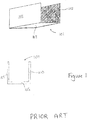
- Such splices generally have a longitudinal length of approximately 100-300mm and a cross section that is similarly-shaped to that of the linear panels, for instance U-shaped, which allows the splice to be accommodated in the end portions of said panels.
- the splice is not usually fixed or attached to the panels, but is instead merely placed within the longitudinal end parts of adjacent linear panels such that it extends within both panels and spans the gap between them.
- the linear panels may be arranged such that they have a small gap (in the order of a few millimetres, for example) between the longitudinal end of one panel and the longitudinal end of the adjacent panel to allow for expansion and contraction of the linear panels, for example due to temperature fluctuations.
- the linear panels may be arranged so that their longitudinal ends abut.
- a panel splice connector configured to splice two adjacent linear panels at their respective longitudinal ends.
- the connector comprises a longitudinally extending base portion, with a length and a width.
- the connector further comprises two wall portions, each extending from the base portion at opposed, longitudinally extending sides thereof.
- the wall portions may extend along the entire length of the connector or along a portion thereof.
- At least one of the wall portions comprises a resilient section that allows a free, longitudinally extending edge of the wall portion to be resiliently displaceable towards the base portion.
- the first region of the or each wall portion may extend from the base portion.
- a third region may be provided, the third region of the respective wall portion extending from the base portion in a direction substantially perpendicular to the base portion, and the third region of the respective wall portion being located between the first region of said wall portion and the base portion.
- the second region of the or each wall portion may extend from the first region.
- one or more intermediate regions may be provided between the first and second regions of the or each wall portion.
- a panel splice connector may be provided, configured to splice two adjacent linear panels at their respective longitudinal ends, the connector comprising a longitudinally extending base portion, having a length and a width, and two wall portions each extending from the base portion at opposed, longitudinally extending sides thereof, wherein a friction material is provided on one or more portions of the panel splice connector that in mounted condition contact the linear panels.
- the friction material may be any other suitable friction material.
- suitable friction materials include rubbers, thermoplastic elastomers (TPE), cellular foams and silicones.
- the friction material may be provided along the whole or part of the longitudinal length of the connector, or may be provided intermittently at intervals along the longitudinal length of the connector.
- the or each resilient section may be configured so as to lie entirely within the contour of the connector as defined by the base portion and the wall portions.
- the or each resilient section may be configured to extend inward from the wall portions, to the interior of the connector, so as not to extend beyond those outer surfaces of the connector that in mounted conditions will be in contact with the linear panels.
- a maximum width of the connector as seen in cross sectional view, may be determined by the width of the base portion and, optionally, the wall portions. The resilient sections do not extend beyond this maximum width.
- the or each resilient section will not interfere with the supporting function of the connector, where the base portion and wall portions abut against and support the longitudinal ends of the linear panels, and even may prevent "springback" thereof, as described later in this specification.
- the or each resilient section may be located nearer to the free, longitudinally extending edge of the wall portions than to the base portion. This too may help preventing the resilient sections from interfering with afore described supporting function of the connector.
- This supporting function can be accomplished by the base portion and the wall portions extending upward from the base portion, up to the resilient sections.
- the base portion and adjoining wall portions may have a conventional shape, ideally matching that of the linear panels that are to be spliced.
- part of the wall portion of the connector may be removed such that a recess is provided in the wall portion of the connector to enable the carrier to engage the panel without interference from the connector.
- the linear panels may be made of any suitable rigid material.
- the linear panels may be made of a metal such as aluminium.
- the connector may be made from any suitable material.
- the connector is made from a sheet metal material, such as aluminium, for example.
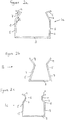
- Figures 2a - 2c show embodiments of connectors 1a - 1c respectively in accordance with the present invention.
- All the connectors have a base portion 3 and two wall portions 5.
- the base portion may be formed integrally with the wall portions, or alternatively may be formed separately from the wall portions and joined thereto.
- the wall portions 5 all comprise a resilient section, that in the illustrated embodiments is formed by a first region 7 which is bent inwardly along the longitudinal length of the connector and a second region 9 which is bent outwardly along the longitudinal length of the connector.
- the first regions 7 of the wall portion 5 and the second regions 9 of the wall portion 5 may be formed from a resilient material.
- first and second regions may itself be formed from a relatively stiff or rigid material but their interconnection may be formed from a resilient material or comprise a hinge.
- the first and second region 7, 9 may be adjacent each other as shown in Figures 2a and 2b or may be separated by an intermediate region 11, as shown in Figure 2c .
- This intermediate region 11 may be hingedly connected to said first and second region 7,9 and/or may itself be formed from a resilient material.
- the angle ⁇ between the first region 7 and the second region 9 of a wall portion 5 is in the range of 70 - 90 degrees.
- the first and second regions (and also any intermediate region present) may be formed integrally with each other.
- the connector may also comprise a third region 13 of the wall portion 5 as shown in Figures 2a and 2c .
- the first and second regions may be formed integrally with the third region 13 of the wall portion 5 and/or the base portion 3.
- the third region 13 of the wall portion 5 and the base portion 3 are not required to be formed from a resilient material.
- the obtuse angle ⁇ between the third region 13 and the first region 7 of a wall portion 5 is in the range of 140 - 160 degrees.
- the connectors 1a - 1c all have a generally U-shaped cross-sectional area shaped and sized to permit the connector to be positioned in a corresponding linear panel.
- Figure 3 shows an isometric view of the panel splice connector 1a of Figure 2a .
- Figures 4a-4c show embodiments of further connectors 1d - If respectively in accordance with the present invention.
- the connectors 1d - 1f are similar to those shown in Figures 2a - 2c respectively, except that the connectors 1 d - 1f further include a friction material 15.
- the friction material 15 is located at the edge 17 of the wall portion 5 remote from (i.e. opposite) the base portion 3. This edge 17 of the wall portion 5 is part of the second region 9 of the wall portion 5.
- the connector may be similar in shape to the one shown if Figure 1 , with friction material similar to that shown in figures 4a - 4c being provided at the edges of the wall portions 105 remote from the base portion 103.
- the friction material may take a form other than a strip, for example a square, oval or circular based shape. Furthermore, the friction material may extend only over apart of the longitudinal length of the connector, and may be provided intermittently at regular or irregular intervals along part or all of the longitudinal length of the connector.
- Figure 6a shows a cross-sectional view of the panel splice connector 1a of Figure 2a located in a linear panel 31.
- the linear panel 31 has a substantially U-shaped cross section, and comprises a panel base portion 33 and two panel side walls 35 extending opposite to each other and away from the panel base portion 33.
- the linear panel 31 also includes flanges 37 located at the edges of the panel side walls 35 remote from the panel base portion 33, the flanges 37 permitting the linear panel 31 to be attached to a panel carrier (not shown).
- the flanges 37 in this example are angled towards the interior of the linear panel 31, however the flanges may instead be substantially parallel to the panel base portion 33 and/or substantially perpendicular to the panel side walls 35, or angled away from the interior of the linear panel.
- the connector 1d has a U-shaped cross section similar to that of the linear panel 31, and is sized to fit readily yet snugly into the linear panel 31.
- the friction material 15 located at the edge 17 of the second region 9 of each wall portion 5 makes firm contact with the inside surface 39 of the linear panel 31 and serves to grip the inside surface 39, thereby holding the linear panel 31 and the connector 1d tightly together. This prevents the connector from moving relative to the panel, and, when the connector is installed in two adjacent linear panels to splice the longitudinal ends of the two linear panels together, relative movement between the two linear panels is prevented.
- the connector 1d Due to the coefficient of friction between the friction material 15 and the inside surface 39 of the linear panel 31 being greater than the coefficient of friction between the second region 9 of the wall portion 5 of the connector 1d and the inside surface 39 of the linear panel 31, the connector 1d is better able to maintain its position in the linear panel 31 than the connector 1a when forces are applied, e.g. during expansion or contraction of a panel due to temperature fluctuations.
- the friction material 15 may have a thickness in the range of 0.1 to 5mm to provide a good friction fit between the friction material 15 and the inside surface 39 of the linear panel 31.
- Figure 7a shows the panel splice connector 1 d of Figure 4a in the process of being placed in a linear panel 31.
- the connector 1d is arranged so that approximately half of its longitudinal length is placed in the linear panel 31, the other half being for placement in a second linear panel (not shown) which is to be positioned so that its longitudinal end abuts the longitudinal end of the linear panel 31.
- the friction material 15 of the connector 1d can be seen in Figure 7a to be near to and protruding above the flange 37 of the linear panel 31.
- the panel side walls 35 of the linear panel 31 can be seen to be angled outwardly at their longitudinal end, such that they are not perpendicular to the panel base portion 33. When manufacturing linear panels, this outward deformation of the panel side walls at their longitudinal ends is a problem which can occur due to cutting the panel to a required length, and is referred to as "springback".
- Figure 7b shows the connector of Figures 4b and 7a once it has been positioned in the linear panel 31.
- the compression force is removed and the resilient material acts to restore the wall portion 5 to its original form as shown in Figure 7c .
- the connector 1d exerts a force on the panel in a direction perpendicular to and away from the panel base portion 33 (i.e. an upward direction in Figures 7a - 7c ).
- the force exerted on the panel by the connector advantageously causes the panel side walls 35 to straighten such that they become substantially perpendicular to the panel base portion 33 by conforming to the shape of the third region 13 of the connector.
- the first and second regions of the connector are preferably relatively small compared to the third region, but should be sufficiently large enough to permit the connector to function in the manner described above.
- the connector shown in Figures 7a - 7c includes a friction material, this is an optional feature.
- a suitable friction material may be desirable in order to allow the connector to be even more firmly positioned in the linear panels and to even better resist movement of adjacent linear panels, especially in situations where the linear panels may be subject to external forces or may be likely to be subject to forces (in longitudinal and/or lateral direction) resulting for example from one or more panels undergoing thermal expansion, contraction and/or afore described springback.
- Figure 8 shows a connector 1g similar to connector 1d depicted in Figure 5 , except that the connector 1g has a recess 41 formed in each of the wall portions 5 of the connector 1g.
- the recess 41 is configured to accommodate an associated panel carrier (not shown) and may be formed at any desired point along the longitudinal length of the connector. This permits a carrier to be positioned, if desired, at the location of the connector.
- the recess 41 is shown extending through the first 7 and second 9 regions of the wall portion 5, however, the recess may extend deeper or shallower into the wall portion 5, depending upon the configuration of the associated connector.
- the recess 41 may also be applied to any of the other connectors described in or implicit from this disclosure, and is not limited to the connector depicted in Figure 8 .
- the splice connector according to the present invention has several advantages over the prior art splice previously described.
- the connector is able to partially or wholly correct deformations in the panel side walls resulting from manufacture (such as "springback"), as described above.
- a further advantage is that, as the connector is configured to exhibit a tight friction fit with the linear panel, where panels are subjected to external forces or to rising or falling temperatures, for example, any movement caused by the external forces or by the expansion or contraction of panels due to thermal fluctuations does not readily result in relative movement between the linear panel and the connector.
- This permits the connector to maintain two adjacent panels in alignment when their longitudinal ends are spliced by the connector.
- the panels are prevented from moving apart from each other, which would result in the splice becoming visible through the gap in the panels and could also reduce the structural integrity of the panel arrangement.
- the connector of the present invention acts to provide support and structural integrity to the shape of the linear panels, and also acts to mechanically connect and thereby strengthen the panel arrangement.
- the prior art splice merely fits loosely between the panels and is able to move relative to the panels. It offers little support or strengthening of the panel arrangement.
- a panel carrier has to be provided to support each panel near its longitudinal end, proximate to the prior art splice, as this splice provides no structural support. This requires two carriers to be placed in relatively close proximity to each other, and gives very little freedom in terms of where the carriers might be placed.
- the connector of the present invention provides a strong mechanical connection between the linear panels, eliminating the need to provide carriers to support the panels at each side of each splice. This results in fewer carriers being required, with a subsequent reduction in cost, and in manufacturing time and installation time. Furthermore, the structural integrity of the connected panels is greatly enhanced, permitting the carriers to be located at positions other than proximate to a splice. This permits greater freedom in selecting the location of the carriers. Additionally, the present invention has the advantage that, if a recess or cut-out portion is provided in each wall portion of the connector as described above with reference to Figure 8 , it is possible to place a carrier at the location of the splice.
Landscapes
- Engineering & Computer Science (AREA)
- Architecture (AREA)
- General Engineering & Computer Science (AREA)
- Civil Engineering (AREA)
- Structural Engineering (AREA)
- Mechanical Engineering (AREA)
- Finishing Walls (AREA)
- Building Environments (AREA)
Applications Claiming Priority (1)
| Application Number | Priority Date | Filing Date | Title |
|---|---|---|---|
| NL1041856A NL1041856B1 (en) | 2016-05-09 | 2016-05-09 | Panels Spilce Connector for Linear Panels. |
Publications (2)
| Publication Number | Publication Date |
|---|---|
| EP3243976A1 true EP3243976A1 (de) | 2017-11-15 |
| EP3243976B1 EP3243976B1 (de) | 2022-04-13 |
Family
ID=57104089
Family Applications (1)
| Application Number | Title | Priority Date | Filing Date |
|---|---|---|---|
| EP17169788.1A Active EP3243976B1 (de) | 2016-05-09 | 2017-05-05 | Plattenspleissverbinder für lineare deckenplatten |
Country Status (5)
| Country | Link |
|---|---|
| US (1) | US10851821B2 (de) |
| EP (1) | EP3243976B1 (de) |
| AU (1) | AU2017203041B2 (de) |
| CA (1) | CA2966339A1 (de) |
| NL (1) | NL1041856B1 (de) |
Families Citing this family (3)
| Publication number | Priority date | Publication date | Assignee | Title |
|---|---|---|---|---|
| JP7053206B2 (ja) * | 2017-09-29 | 2022-04-12 | ニチハ株式会社 | 取付具及び建物の壁構造 |
| WO2019091540A1 (en) * | 2017-11-13 | 2019-05-16 | Knauf Gips Kg | Profile and construction element set for arranging a component for a drywall construction, and drywall formed therewith |
| CN116312261B (zh) * | 2023-04-28 | 2026-02-13 | 上海天马微电子有限公司 | 显示面板和显示装置 |
Citations (4)
| Publication number | Priority date | Publication date | Assignee | Title |
|---|---|---|---|---|
| US3336711A (en) * | 1965-09-10 | 1967-08-22 | Henry F Menke | Wall covering system |
| US3509675A (en) * | 1967-10-23 | 1970-05-05 | Star Mfg Co | Wall paneling having concealed connection regions |
| EP0062756A1 (de) * | 1981-03-30 | 1982-10-20 | H.H. Robertson Company | Haltevorrichtung für Platten und Wand- oder Dachstruktur mit selbiger Haltevorrichtung |
| WO2008003232A1 (en) * | 2006-06-26 | 2008-01-10 | Luhao Leng | Composite plastic wall brick |
Family Cites Families (36)
| Publication number | Priority date | Publication date | Assignee | Title |
|---|---|---|---|---|
| US2150130A (en) * | 1935-09-17 | 1939-03-07 | Budd Edward G Mfg Co | Removable paneling |
| US2833575A (en) * | 1954-05-13 | 1958-05-06 | Millard E Haller | Sleeve for joining t bars in installing tile |
| US2934184A (en) * | 1957-11-19 | 1960-04-26 | John C Virden Company | Fastener and closure device |
| US3588151A (en) * | 1970-06-01 | 1971-06-28 | Fedders Corp | Tubing clip |
| US3673402A (en) * | 1970-10-19 | 1972-06-27 | Harvey I Weiss | Extendible lighting fixture |
| DE2109117A1 (de) * | 1971-02-26 | 1972-09-07 | Pfannenberg Gmbh | Verbindung von stumpf aneinanderstoßenden Hohiprofilstäben |
| US3671062A (en) * | 1971-05-13 | 1972-06-20 | United States Steel Corp | Internal coupling for connecting u-shaped rails |
| US4117638A (en) * | 1977-11-25 | 1978-10-03 | Atlanta Metal Products, Inc. | Skylight for standing rib metal roofs |
| US4222552A (en) * | 1978-10-20 | 1980-09-16 | Matteo Sr George W | Highway guardrail cover |
| US4305677A (en) * | 1979-10-04 | 1981-12-15 | B-Line Systems, Inc. | Connector |
| DE3219138A1 (de) * | 1982-05-21 | 1983-11-24 | Richter-System GmbH & Co KG, 6103 Griesheim | Paneelverbinder |
| FR2624172B1 (fr) * | 1987-12-07 | 1991-04-05 | Humeau Michel | Ossature legere de second oeuvre |
| US4843746A (en) * | 1988-01-11 | 1989-07-04 | Signlite Services, Inc. | Outdoor support post apparatus |
| IT1218229B (it) * | 1988-04-28 | 1990-04-12 | Giovanni Celsi | Tamponatura autotrasportante traslucida per costruzioni edili |
| NZ245193A (en) * | 1991-11-20 | 1995-11-27 | Stratco Australia Pty Ltd | U-shaped bracket base fitted in end of a tubular member and bracket arms clamped to opposite grooved sides of adjoining frame member |
| DE4322631C2 (de) * | 1993-07-07 | 1995-05-24 | Richter System Gmbh & Co Kg | Verbinder für C-Profile |
| DE9401416U1 (de) * | 1994-01-28 | 1994-03-10 | Vogl, Erich R., 91448 Emskirchen | Verbindungselement zum Längsverbinden von C-Profilen |
| US6146048A (en) * | 1998-05-13 | 2000-11-14 | Stibolt; Paul E. | Connector for two drywall corner finishing devices |
| US6996946B1 (en) * | 1999-02-26 | 2006-02-14 | Sergio Cazzolaro | Structures which can be dismantled and folded, consisting of interconnecting tubular elements |
| DE19908585A1 (de) * | 1999-02-27 | 2000-08-31 | Profil Vertrieb Gmbh | An einem Verankerungsgrund anbringbares Profil |
| US7204064B2 (en) * | 2000-02-18 | 2007-04-17 | Sergio Cazzolaro | Structures which can be dismantled and folded, consisting of interconnecting tubular elements |
| FR2848269B1 (fr) * | 2002-12-09 | 2006-06-30 | Profilage Du Poitou S P P Soc | Dispositif d'assemblage complementaire pour fourrures de montage de parements |
| FR2856444B1 (fr) * | 2003-06-20 | 2008-07-11 | Profilage Du Poitou S P P Soc | Dispositif d'assemblage complementaire pour fourrures de montage de parements |
| DE10351395A1 (de) * | 2003-11-04 | 2005-06-09 | Bosch Rexroth Ag | Verbindungselement unter Verwendung eines solchen Verbindungselements realisierte Montageeinheit |
| US7210273B2 (en) * | 2003-11-19 | 2007-05-01 | A. Zahner Company | Panel attachment system |
| US7618210B2 (en) * | 2006-03-01 | 2009-11-17 | R & B Wagner, Inc. | Pipe and tubing connector |
| FR2900219B1 (fr) * | 2006-04-25 | 2010-07-30 | Lafarge Platres | Eclisse, procede d'assemblage d'ossature utilisant cette eclisse et ossature ainsi obtenue |
| WO2010096441A1 (en) * | 2009-02-17 | 2010-08-26 | Technical Specialties, Inc. | Raceway for instrumentation lines |
| DE102011015435A1 (de) * | 2011-03-29 | 2012-10-04 | Protektorwerk Florenz Maisch Gmbh & Co. Kg | Verbindungselement und Verfahren zu dessen Herstellung |
| DE202013100161U1 (de) * | 2013-01-11 | 2013-02-25 | Knauf Gips Kg | Trockenbaudecke/-wand |
| DE202013007676U1 (de) * | 2013-08-28 | 2014-12-01 | Huwer GmbH | Verbindungselement für Profilschienen |
| FR3027930B1 (fr) * | 2014-11-03 | 2016-12-16 | Profiles Sud Pyrenees | Profile prolongateur pour la realisation d'une paroi murale, montant telescopique et procede de montage |
| DE202014105547U1 (de) * | 2014-11-19 | 2016-02-22 | Max Kronenberg | Steckverbinder und Steckverbindung |
| EP3098364A1 (de) * | 2015-05-27 | 2016-11-30 | Sika Technology AG | Profilsystem zur fixierung von abdeckungen, insbesondere dachdichtungsbahnen |
| US9741269B2 (en) * | 2015-12-07 | 2017-08-22 | Sign Post Solutions, LLC | Modular signpost system |
| US10072425B1 (en) * | 2016-01-26 | 2018-09-11 | Michael Madden | Splice coupling for connection of tubular handrail sections |
-
2016
- 2016-05-09 NL NL1041856A patent/NL1041856B1/en active
-
2017
- 2017-05-05 US US15/587,585 patent/US10851821B2/en active Active
- 2017-05-05 EP EP17169788.1A patent/EP3243976B1/de active Active
- 2017-05-08 AU AU2017203041A patent/AU2017203041B2/en active Active
- 2017-05-10 CA CA2966339A patent/CA2966339A1/en active Pending
Patent Citations (4)
| Publication number | Priority date | Publication date | Assignee | Title |
|---|---|---|---|---|
| US3336711A (en) * | 1965-09-10 | 1967-08-22 | Henry F Menke | Wall covering system |
| US3509675A (en) * | 1967-10-23 | 1970-05-05 | Star Mfg Co | Wall paneling having concealed connection regions |
| EP0062756A1 (de) * | 1981-03-30 | 1982-10-20 | H.H. Robertson Company | Haltevorrichtung für Platten und Wand- oder Dachstruktur mit selbiger Haltevorrichtung |
| WO2008003232A1 (en) * | 2006-06-26 | 2008-01-10 | Luhao Leng | Composite plastic wall brick |
Also Published As
| Publication number | Publication date |
|---|---|
| AU2017203041A1 (en) | 2017-11-23 |
| EP3243976B1 (de) | 2022-04-13 |
| US10851821B2 (en) | 2020-12-01 |
| CA2966339A1 (en) | 2017-11-09 |
| AU2017203041B2 (en) | 2022-09-29 |
| NL1041856B1 (en) | 2017-11-16 |
| US20170321732A1 (en) | 2017-11-09 |
Similar Documents
| Publication | Publication Date | Title |
|---|---|---|
| CN103635641B (zh) | 用于将两个并置的板安装到结构从而允许热膨胀和收缩的组件 | |
| EP2370649B1 (de) | Verborgene zwischendecke mit abwärts beweglichen platten | |
| US9209609B2 (en) | Cable tray system with splice plate | |
| US8966849B1 (en) | System for mounting wall panels to a wall structure | |
| AU2017203768B2 (en) | Exterior-material securing member and building exterior structure | |
| US8250822B2 (en) | Wall framing system, method and product | |
| US9673752B2 (en) | Photovoltaic array skirt and mounting hardware | |
| US20110099928A1 (en) | Deflection and drift structural wall assemblies | |
| US11274440B2 (en) | Suspension ceiling support clip | |
| AU2017203041B2 (en) | Panel splice connector for linear ceiling panels | |
| US5653076A (en) | Method and system for assembling a wall | |
| KR20180100960A (ko) | 내진용 슬라이딩 고정클립 및 이를 이용한 외장재의 시공방법 | |
| KR101572981B1 (ko) | 데크 보드 조립체의 데크 보드 고정용 클립 | |
| IE47934B1 (en) | A device for joining panels | |
| WO2009145367A1 (en) | Deck fastener and structure for connecting deck board | |
| RS51749B (sr) | Spojni element za c-profil sa sredstvom za kompenzaciju i sistemom | |
| JP6751303B2 (ja) | 固定用金具 | |
| AU2016206190A1 (en) | Roof clip | |
| JPH08218502A (ja) | 外壁パネルの目地用シーリング材の構造 | |
| RU2633458C1 (ru) | Удерживающий зажим с обеспечением возможности теплового расширения | |
| WO1997004190A1 (en) | A device for attaching a wall element to a backing structure | |
| JP7780289B2 (ja) | 雨樋システム及び接続部材 | |
| EP4571010A1 (de) | Abdeckungsanordnung und verfahren zur verbindung von abdeckelementen | |
| JPS60156852A (ja) | 断熱嵌合外囲体 | |
| JPS6328347Y2 (de) |
Legal Events
| Date | Code | Title | Description |
|---|---|---|---|
| PUAI | Public reference made under article 153(3) epc to a published international application that has entered the european phase |
Free format text: ORIGINAL CODE: 0009012 |
|
| STAA | Information on the status of an ep patent application or granted ep patent |
Free format text: STATUS: THE APPLICATION HAS BEEN PUBLISHED |
|
| AK | Designated contracting states |
Kind code of ref document: A1 Designated state(s): AL AT BE BG CH CY CZ DE DK EE ES FI FR GB GR HR HU IE IS IT LI LT LU LV MC MK MT NL NO PL PT RO RS SE SI SK SM TR |
|
| AX | Request for extension of the european patent |
Extension state: BA ME |
|
| STAA | Information on the status of an ep patent application or granted ep patent |
Free format text: STATUS: REQUEST FOR EXAMINATION WAS MADE |
|
| 17P | Request for examination filed |
Effective date: 20180511 |
|
| RBV | Designated contracting states (corrected) |
Designated state(s): AL AT BE BG CH CY CZ DE DK EE ES FI FR GB GR HR HU IE IS IT LI LT LU LV MC MK MT NL NO PL PT RO RS SE SI SK SM TR |
|
| STAA | Information on the status of an ep patent application or granted ep patent |
Free format text: STATUS: EXAMINATION IS IN PROGRESS |
|
| 17Q | First examination report despatched |
Effective date: 20200113 |
|
| RIC1 | Information provided on ipc code assigned before grant |
Ipc: E04F 13/08 20060101AFI20210705BHEP Ipc: E04F 13/12 20060101ALI20210705BHEP |
|
| GRAP | Despatch of communication of intention to grant a patent |
Free format text: ORIGINAL CODE: EPIDOSNIGR1 |
|
| STAA | Information on the status of an ep patent application or granted ep patent |
Free format text: STATUS: GRANT OF PATENT IS INTENDED |
|
| GRAJ | Information related to disapproval of communication of intention to grant by the applicant or resumption of examination proceedings by the epo deleted |
Free format text: ORIGINAL CODE: EPIDOSDIGR1 |
|
| GRAP | Despatch of communication of intention to grant a patent |
Free format text: ORIGINAL CODE: EPIDOSNIGR1 |
|
| INTG | Intention to grant announced |
Effective date: 20211013 |
|
| INTG | Intention to grant announced |
Effective date: 20211027 |
|
| GRAS | Grant fee paid |
Free format text: ORIGINAL CODE: EPIDOSNIGR3 |
|
| GRAA | (expected) grant |
Free format text: ORIGINAL CODE: 0009210 |
|
| STAA | Information on the status of an ep patent application or granted ep patent |
Free format text: STATUS: THE PATENT HAS BEEN GRANTED |
|
| AK | Designated contracting states |
Kind code of ref document: B1 Designated state(s): AL AT BE BG CH CY CZ DE DK EE ES FI FR GB GR HR HU IE IS IT LI LT LU LV MC MK MT NL NO PL PT RO RS SE SI SK SM TR |
|
| REG | Reference to a national code |
Ref country code: GB Ref legal event code: FG4D |
|
| REG | Reference to a national code |
Ref country code: CH Ref legal event code: EP |
|
| REG | Reference to a national code |
Ref country code: DE Ref legal event code: R096 Ref document number: 602017055805 Country of ref document: DE |
|
| REG | Reference to a national code |
Ref country code: IE Ref legal event code: FG4D |
|
| REG | Reference to a national code |
Ref country code: AT Ref legal event code: REF Ref document number: 1483521 Country of ref document: AT Kind code of ref document: T Effective date: 20220515 |
|
| REG | Reference to a national code |
Ref country code: NL Ref legal event code: FP |
|
| REG | Reference to a national code |
Ref country code: LT Ref legal event code: MG9D |
|
| REG | Reference to a national code |
Ref country code: AT Ref legal event code: MK05 Ref document number: 1483521 Country of ref document: AT Kind code of ref document: T Effective date: 20220413 |
|
| PG25 | Lapsed in a contracting state [announced via postgrant information from national office to epo] |
Ref country code: SE Free format text: LAPSE BECAUSE OF FAILURE TO SUBMIT A TRANSLATION OF THE DESCRIPTION OR TO PAY THE FEE WITHIN THE PRESCRIBED TIME-LIMIT Effective date: 20220413 Ref country code: PT Free format text: LAPSE BECAUSE OF FAILURE TO SUBMIT A TRANSLATION OF THE DESCRIPTION OR TO PAY THE FEE WITHIN THE PRESCRIBED TIME-LIMIT Effective date: 20220816 Ref country code: NO Free format text: LAPSE BECAUSE OF FAILURE TO SUBMIT A TRANSLATION OF THE DESCRIPTION OR TO PAY THE FEE WITHIN THE PRESCRIBED TIME-LIMIT Effective date: 20220713 Ref country code: LT Free format text: LAPSE BECAUSE OF FAILURE TO SUBMIT A TRANSLATION OF THE DESCRIPTION OR TO PAY THE FEE WITHIN THE PRESCRIBED TIME-LIMIT Effective date: 20220413 Ref country code: HR Free format text: LAPSE BECAUSE OF FAILURE TO SUBMIT A TRANSLATION OF THE DESCRIPTION OR TO PAY THE FEE WITHIN THE PRESCRIBED TIME-LIMIT Effective date: 20220413 Ref country code: GR Free format text: LAPSE BECAUSE OF FAILURE TO SUBMIT A TRANSLATION OF THE DESCRIPTION OR TO PAY THE FEE WITHIN THE PRESCRIBED TIME-LIMIT Effective date: 20220714 Ref country code: FI Free format text: LAPSE BECAUSE OF FAILURE TO SUBMIT A TRANSLATION OF THE DESCRIPTION OR TO PAY THE FEE WITHIN THE PRESCRIBED TIME-LIMIT Effective date: 20220413 Ref country code: ES Free format text: LAPSE BECAUSE OF FAILURE TO SUBMIT A TRANSLATION OF THE DESCRIPTION OR TO PAY THE FEE WITHIN THE PRESCRIBED TIME-LIMIT Effective date: 20220413 Ref country code: BG Free format text: LAPSE BECAUSE OF FAILURE TO SUBMIT A TRANSLATION OF THE DESCRIPTION OR TO PAY THE FEE WITHIN THE PRESCRIBED TIME-LIMIT Effective date: 20220713 Ref country code: AT Free format text: LAPSE BECAUSE OF FAILURE TO SUBMIT A TRANSLATION OF THE DESCRIPTION OR TO PAY THE FEE WITHIN THE PRESCRIBED TIME-LIMIT Effective date: 20220413 |
|
| PG25 | Lapsed in a contracting state [announced via postgrant information from national office to epo] |
Ref country code: RS Free format text: LAPSE BECAUSE OF FAILURE TO SUBMIT A TRANSLATION OF THE DESCRIPTION OR TO PAY THE FEE WITHIN THE PRESCRIBED TIME-LIMIT Effective date: 20220413 Ref country code: PL Free format text: LAPSE BECAUSE OF FAILURE TO SUBMIT A TRANSLATION OF THE DESCRIPTION OR TO PAY THE FEE WITHIN THE PRESCRIBED TIME-LIMIT Effective date: 20220413 Ref country code: LV Free format text: LAPSE BECAUSE OF FAILURE TO SUBMIT A TRANSLATION OF THE DESCRIPTION OR TO PAY THE FEE WITHIN THE PRESCRIBED TIME-LIMIT Effective date: 20220413 Ref country code: IS Free format text: LAPSE BECAUSE OF FAILURE TO SUBMIT A TRANSLATION OF THE DESCRIPTION OR TO PAY THE FEE WITHIN THE PRESCRIBED TIME-LIMIT Effective date: 20220813 |
|
| REG | Reference to a national code |
Ref country code: CH Ref legal event code: PL |
|
| REG | Reference to a national code |
Ref country code: DE Ref legal event code: R097 Ref document number: 602017055805 Country of ref document: DE |
|
| REG | Reference to a national code |
Ref country code: BE Ref legal event code: MM Effective date: 20220531 |
|
| PG25 | Lapsed in a contracting state [announced via postgrant information from national office to epo] |
Ref country code: SM Free format text: LAPSE BECAUSE OF FAILURE TO SUBMIT A TRANSLATION OF THE DESCRIPTION OR TO PAY THE FEE WITHIN THE PRESCRIBED TIME-LIMIT Effective date: 20220413 Ref country code: SK Free format text: LAPSE BECAUSE OF FAILURE TO SUBMIT A TRANSLATION OF THE DESCRIPTION OR TO PAY THE FEE WITHIN THE PRESCRIBED TIME-LIMIT Effective date: 20220413 Ref country code: RO Free format text: LAPSE BECAUSE OF FAILURE TO SUBMIT A TRANSLATION OF THE DESCRIPTION OR TO PAY THE FEE WITHIN THE PRESCRIBED TIME-LIMIT Effective date: 20220413 Ref country code: MC Free format text: LAPSE BECAUSE OF FAILURE TO SUBMIT A TRANSLATION OF THE DESCRIPTION OR TO PAY THE FEE WITHIN THE PRESCRIBED TIME-LIMIT Effective date: 20220413 Ref country code: LU Free format text: LAPSE BECAUSE OF NON-PAYMENT OF DUE FEES Effective date: 20220505 Ref country code: LI Free format text: LAPSE BECAUSE OF NON-PAYMENT OF DUE FEES Effective date: 20220531 Ref country code: EE Free format text: LAPSE BECAUSE OF FAILURE TO SUBMIT A TRANSLATION OF THE DESCRIPTION OR TO PAY THE FEE WITHIN THE PRESCRIBED TIME-LIMIT Effective date: 20220413 Ref country code: DK Free format text: LAPSE BECAUSE OF FAILURE TO SUBMIT A TRANSLATION OF THE DESCRIPTION OR TO PAY THE FEE WITHIN THE PRESCRIBED TIME-LIMIT Effective date: 20220413 Ref country code: CZ Free format text: LAPSE BECAUSE OF FAILURE TO SUBMIT A TRANSLATION OF THE DESCRIPTION OR TO PAY THE FEE WITHIN THE PRESCRIBED TIME-LIMIT Effective date: 20220413 Ref country code: CH Free format text: LAPSE BECAUSE OF NON-PAYMENT OF DUE FEES Effective date: 20220531 |
|
| PLBE | No opposition filed within time limit |
Free format text: ORIGINAL CODE: 0009261 |
|
| STAA | Information on the status of an ep patent application or granted ep patent |
Free format text: STATUS: NO OPPOSITION FILED WITHIN TIME LIMIT |
|
| 26N | No opposition filed |
Effective date: 20230116 |
|
| PG25 | Lapsed in a contracting state [announced via postgrant information from national office to epo] |
Ref country code: AL Free format text: LAPSE BECAUSE OF FAILURE TO SUBMIT A TRANSLATION OF THE DESCRIPTION OR TO PAY THE FEE WITHIN THE PRESCRIBED TIME-LIMIT Effective date: 20220413 |
|
| REG | Reference to a national code |
Ref country code: FR Ref legal event code: PLFP Year of fee payment: 7 |
|
| PG25 | Lapsed in a contracting state [announced via postgrant information from national office to epo] |
Ref country code: IE Free format text: LAPSE BECAUSE OF NON-PAYMENT OF DUE FEES Effective date: 20220505 |
|
| PG25 | Lapsed in a contracting state [announced via postgrant information from national office to epo] |
Ref country code: SI Free format text: LAPSE BECAUSE OF FAILURE TO SUBMIT A TRANSLATION OF THE DESCRIPTION OR TO PAY THE FEE WITHIN THE PRESCRIBED TIME-LIMIT Effective date: 20220413 Ref country code: BE Free format text: LAPSE BECAUSE OF NON-PAYMENT OF DUE FEES Effective date: 20220531 |
|
| P01 | Opt-out of the competence of the unified patent court (upc) registered |
Effective date: 20230331 |
|
| PG25 | Lapsed in a contracting state [announced via postgrant information from national office to epo] |
Ref country code: IT Free format text: LAPSE BECAUSE OF FAILURE TO SUBMIT A TRANSLATION OF THE DESCRIPTION OR TO PAY THE FEE WITHIN THE PRESCRIBED TIME-LIMIT Effective date: 20220413 |
|
| PG25 | Lapsed in a contracting state [announced via postgrant information from national office to epo] |
Ref country code: HU Free format text: LAPSE BECAUSE OF FAILURE TO SUBMIT A TRANSLATION OF THE DESCRIPTION OR TO PAY THE FEE WITHIN THE PRESCRIBED TIME-LIMIT; INVALID AB INITIO Effective date: 20170505 |
|
| PG25 | Lapsed in a contracting state [announced via postgrant information from national office to epo] |
Ref country code: MK Free format text: LAPSE BECAUSE OF FAILURE TO SUBMIT A TRANSLATION OF THE DESCRIPTION OR TO PAY THE FEE WITHIN THE PRESCRIBED TIME-LIMIT Effective date: 20220413 Ref country code: CY Free format text: LAPSE BECAUSE OF FAILURE TO SUBMIT A TRANSLATION OF THE DESCRIPTION OR TO PAY THE FEE WITHIN THE PRESCRIBED TIME-LIMIT Effective date: 20220413 |
|
| PG25 | Lapsed in a contracting state [announced via postgrant information from national office to epo] |
Ref country code: MT Free format text: LAPSE BECAUSE OF FAILURE TO SUBMIT A TRANSLATION OF THE DESCRIPTION OR TO PAY THE FEE WITHIN THE PRESCRIBED TIME-LIMIT Effective date: 20220413 |
|
| PG25 | Lapsed in a contracting state [announced via postgrant information from national office to epo] |
Ref country code: BG Free format text: LAPSE BECAUSE OF FAILURE TO SUBMIT A TRANSLATION OF THE DESCRIPTION OR TO PAY THE FEE WITHIN THE PRESCRIBED TIME-LIMIT Effective date: 20220413 |
|
| PG25 | Lapsed in a contracting state [announced via postgrant information from national office to epo] |
Ref country code: BG Free format text: LAPSE BECAUSE OF FAILURE TO SUBMIT A TRANSLATION OF THE DESCRIPTION OR TO PAY THE FEE WITHIN THE PRESCRIBED TIME-LIMIT Effective date: 20220413 |
|
| PGFP | Annual fee paid to national office [announced via postgrant information from national office to epo] |
Ref country code: NL Payment date: 20250526 Year of fee payment: 9 |
|
| PGFP | Annual fee paid to national office [announced via postgrant information from national office to epo] |
Ref country code: DE Payment date: 20250528 Year of fee payment: 9 |
|
| PGFP | Annual fee paid to national office [announced via postgrant information from national office to epo] |
Ref country code: GB Payment date: 20250520 Year of fee payment: 9 |
|
| PGFP | Annual fee paid to national office [announced via postgrant information from national office to epo] |
Ref country code: FR Payment date: 20250526 Year of fee payment: 9 |
|
| PG25 | Lapsed in a contracting state [announced via postgrant information from national office to epo] |
Ref country code: TR Free format text: LAPSE BECAUSE OF FAILURE TO SUBMIT A TRANSLATION OF THE DESCRIPTION OR TO PAY THE FEE WITHIN THE PRESCRIBED TIME-LIMIT Effective date: 20220413 |