EP3244014A2 - Bague de retenue - Google Patents
Bague de retenue Download PDFInfo
- Publication number
- EP3244014A2 EP3244014A2 EP17158977.3A EP17158977A EP3244014A2 EP 3244014 A2 EP3244014 A2 EP 3244014A2 EP 17158977 A EP17158977 A EP 17158977A EP 3244014 A2 EP3244014 A2 EP 3244014A2
- Authority
- EP
- European Patent Office
- Prior art keywords
- retaining ring
- cover plate
- rotor
- rotor disk
- assembly
- Prior art date
- Legal status (The legal status is an assumption and is not a legal conclusion. Google has not performed a legal analysis and makes no representation as to the accuracy of the status listed.)
- Granted
Links
Images


Classifications
-
- F—MECHANICAL ENGINEERING; LIGHTING; HEATING; WEAPONS; BLASTING
- F01—MACHINES OR ENGINES IN GENERAL; ENGINE PLANTS IN GENERAL; STEAM ENGINES
- F01D—NON-POSITIVE DISPLACEMENT MACHINES OR ENGINES, e.g. STEAM TURBINES
- F01D5/00—Blades; Blade-carrying members; Heating, heat-insulating, cooling or antivibration means on the blades or the members
- F01D5/30—Fixing blades to rotors; Blade roots ; Blade spacers
- F01D5/3007—Fixing blades to rotors; Blade roots ; Blade spacers of axial insertion type
- F01D5/3015—Fixing blades to rotors; Blade roots ; Blade spacers of axial insertion type with side plates
-
- F—MECHANICAL ENGINEERING; LIGHTING; HEATING; WEAPONS; BLASTING
- F01—MACHINES OR ENGINES IN GENERAL; ENGINE PLANTS IN GENERAL; STEAM ENGINES
- F01D—NON-POSITIVE DISPLACEMENT MACHINES OR ENGINES, e.g. STEAM TURBINES
- F01D11/00—Preventing or minimising internal leakage of working-fluid, e.g. between stages
- F01D11/005—Sealing means between non relatively rotating elements
- F01D11/006—Sealing the gap between rotor blades or blades and rotor
-
- F—MECHANICAL ENGINEERING; LIGHTING; HEATING; WEAPONS; BLASTING
- F05—INDEXING SCHEMES RELATING TO ENGINES OR PUMPS IN VARIOUS SUBCLASSES OF CLASSES F01-F04
- F05D—INDEXING SCHEME FOR ASPECTS RELATING TO NON-POSITIVE-DISPLACEMENT MACHINES OR ENGINES, GAS-TURBINES OR JET-PROPULSION PLANTS
- F05D2220/00—Application
- F05D2220/30—Application in turbines
- F05D2220/32—Application in turbines in gas turbines
-
- F—MECHANICAL ENGINEERING; LIGHTING; HEATING; WEAPONS; BLASTING
- F05—INDEXING SCHEMES RELATING TO ENGINES OR PUMPS IN VARIOUS SUBCLASSES OF CLASSES F01-F04
- F05D—INDEXING SCHEME FOR ASPECTS RELATING TO NON-POSITIVE-DISPLACEMENT MACHINES OR ENGINES, GAS-TURBINES OR JET-PROPULSION PLANTS
- F05D2240/00—Components
- F05D2240/20—Rotors
-
- F—MECHANICAL ENGINEERING; LIGHTING; HEATING; WEAPONS; BLASTING
- F05—INDEXING SCHEMES RELATING TO ENGINES OR PUMPS IN VARIOUS SUBCLASSES OF CLASSES F01-F04
- F05D—INDEXING SCHEME FOR ASPECTS RELATING TO NON-POSITIVE-DISPLACEMENT MACHINES OR ENGINES, GAS-TURBINES OR JET-PROPULSION PLANTS
- F05D2260/00—Function
- F05D2260/30—Retaining components in desired mutual position
-
- F—MECHANICAL ENGINEERING; LIGHTING; HEATING; WEAPONS; BLASTING
- F05—INDEXING SCHEMES RELATING TO ENGINES OR PUMPS IN VARIOUS SUBCLASSES OF CLASSES F01-F04
- F05D—INDEXING SCHEME FOR ASPECTS RELATING TO NON-POSITIVE-DISPLACEMENT MACHINES OR ENGINES, GAS-TURBINES OR JET-PROPULSION PLANTS
- F05D2260/00—Function
- F05D2260/94—Functionality given by mechanical stress related aspects such as low cycle fatigue [LCF] of high cycle fatigue [HCF]
- F05D2260/941—Functionality given by mechanical stress related aspects such as low cycle fatigue [LCF] of high cycle fatigue [HCF] particularly aimed at mechanical or thermal stress reduction
-
- F—MECHANICAL ENGINEERING; LIGHTING; HEATING; WEAPONS; BLASTING
- F16—ENGINEERING ELEMENTS AND UNITS; GENERAL MEASURES FOR PRODUCING AND MAINTAINING EFFECTIVE FUNCTIONING OF MACHINES OR INSTALLATIONS; THERMAL INSULATION IN GENERAL
- F16B—DEVICES FOR FASTENING OR SECURING CONSTRUCTIONAL ELEMENTS OR MACHINE PARTS TOGETHER, e.g. NAILS, BOLTS, CIRCLIPS, CLAMPS, CLIPS OR WEDGES; JOINTS OR JOINTING
- F16B21/00—Means for preventing relative axial movement of a pin, spigot, shaft or the like and a member surrounding it; Stud-and-socket releasable fastenings
- F16B21/10—Means for preventing relative axial movement of a pin, spigot, shaft or the like and a member surrounding it; Stud-and-socket releasable fastenings by separate parts
- F16B21/16—Means for preventing relative axial movement of a pin, spigot, shaft or the like and a member surrounding it; Stud-and-socket releasable fastenings by separate parts with grooves or notches in the pin or shaft
- F16B21/18—Means for preventing relative axial movement of a pin, spigot, shaft or the like and a member surrounding it; Stud-and-socket releasable fastenings by separate parts with grooves or notches in the pin or shaft with circlips or like resilient retaining devices, i.e. resilient in the plane of the ring or the like; Details
Definitions
- the present disclosure relates to gas turbine engines, and, more specifically, to a retaining ring for a rotor cover plate.
- a gas turbine engine typically includes a fan section, a compressor section, a combustor section, and a turbine section.
- air is pressurized in the compressor section and is mixed with fuel and burned in the combustor section to generate hot combustion gases.
- the hot combustion gases flow through the turbine section, which extracts energy from the hot combustion gases to power the compressor section and other gas turbine engine loads.
- the compressor section typically includes low pressure and high pressure compressors, and the turbine section includes low pressure and high pressure turbines.
- Turbine and compressor rotors may include a rotor disk and a plurality of circumferentially spaced turbine blades.
- Rotor disks may include cover plates attached thereto. Rotor disks cover plates may be subject to high radial forces. Further, cover plates may be subject to high stress at the contact surfaces of cover plates, which may reduce the performance and operating life of the cover plates.
- a retaining ring assembly for a gas turbine engine may include a first engine component and a second engine component.
- a retaining ring may be disposed between the first engine component and the second engine component.
- the retaining ring may be circumferentially discontinuous and may include a first terminal portion having at least one of a tapered or a contoured geometry.
- a thickness of the retaining ring at the first terminal portion may be less than a thickness of the retaining ring away from the first terminal portion.
- the contoured geometry of the first terminal portion may include a rounded terminal edge.
- a first terminal edge and a second terminal edge of the retaining ring may define an opening extending radially though the retaining ring.
- An inner surface of the retaining ring may slope away from the first engine component and toward the first terminal edge.
- An outer surface of the retaining ring may slope away from the second engine component and toward the second terminal edge.
- the outer surface of the retaining ring may include a curved slope.
- a rotor assembly of a gas turbine engine may include a rotor disk and a rotor blade coupled to the rotor disk, the rotor disk configured to rotate about an axis.
- the rotor assembly may include a retaining ring assembly.
- the retaining ring assembly may include a flange extending axially from the rotor disk.
- a cover plate may be disposed between the flange and the rotor disk.
- a retaining ring may be disposed between the flange and the cover plate.
- the retaining ring may be circumferentially discontinuous and may include a first terminal portion having at least one of a tapered or a contoured geometry.
- the contoured geometry of the first terminal portion may include a rounded terminal edge.
- a thickness of the retaining ring at the first terminal portion may be less than a thickness of the retaining ring away from the first terminal portion.
- a first terminal edge and a second terminal edge of the retaining ring may define an opening extending radially though the retaining ring.
- An inner surface of the retaining ring may slope away from the cover plate and toward the first terminal edge.
- An outer surface of the retaining ring may slope away from the flange and toward the second terminal edge.
- the outer surface of the retaining ring may include a curved slope.
- the cover plate may be disposed circumferentially along a radially outward edge of the rotor disk.
- the rotor assembly may be a part of a compressor section or a turbine section.
- the gas turbine engine may include a turbine section including a rotor assembly.
- the rotor assembly may include a rotor disk and a rotor blade coupled to the rotor disk.
- the rotor disk may be configured to rotate about an axis.
- the rotor assembly may further include a retaining ring assembly.
- the retaining ring assembly may include a flange extending axially from the rotor disk.
- a cover plate may be disposed between the flange and the rotor disk.
- a retaining ring may be disposed between the flange and the cover plate.
- the retaining ring may be circumferentially discontinuous and may include a first terminal portion having at least one of a tapered or a contoured geometry.
- the contoured geometry of the first terminal portion may include a rounded terminal edge.
- An inner surface of the retaining ring may slope away from the cover plate at the first terminal portion.
- a thickness of the retaining ring at the first terminal portion may be less than a thickness of the retaining ring away from the first terminal portion.
- any reference to attached, fixed, connected, or the like may include permanent, removable, temporary, partial, full, and/or any other possible attachment option. Additionally, any reference to without contact (or similar phrases) may also include reduced contact or minimal contact.
- Cross hatching lines may be used throughout the figures to denote different parts but not necessarily to denote the same or different materials.
- tail refers to the direction associated with the tail (e.g., the back end) of an aircraft, or generally, to the direction of exhaust of the gas turbine engine.
- forward refers to the direction associated with the nose (e.g., the front end) of an aircraft, or generally, to the direction of flight or motion.
- distal refers to the direction radially outward, or generally, away from the axis of rotation of a turbine engine.
- proximal refers to a direction radially inward, or generally, towards the axis of rotation of a turbine engine.
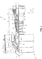
- Gas turbine engine 20 may be a two-spool turbofan that generally incorporates a fan section 22, a compressor section 24, a combustor section 26 and a turbine section 28.
- Alternative engines may include, for example, an augmentor section among other systems or features.
- fan section 22 can drive coolant (e.g., air) along a bypass flow-path B while compressor section 24 can drive coolant along a core flow-path C for compression and communication into combustor section 26 then expansion through turbine section 28.
- coolant e.g., air
- compressor section 24 can drive coolant along a core flow-path C for compression and communication into combustor section 26 then expansion through turbine section 28.
- Gas turbine engine 20 may generally comprise a low speed spool 30 and a high speed spool 32 mounted for rotation about an engine central longitudinal axis A-A' relative to an engine static structure 36 or engine case via several bearing systems 38, 38-1, and 38-2.
- Engine central longitudinal axis A-A' is oriented in the z direction on the provided xyz axis. It should be understood that various bearing systems 38 at various locations may alternatively or additionally be provided, including for example, bearing system 38, bearing system 38-1, and bearing system 38-2.
- Low speed spool 30 may generally comprise an inner shaft 40 that interconnects a fan 42, a low pressure compressor 44 and a low pressure turbine 46.
- Inner shaft 40 may be connected to fan 42 through a geared architecture 48 that can drive fan 42 at a lower speed than low speed spool 30.
- Geared architecture 48 may comprise a gear assembly 60 enclosed within a gear housing 62.
- Gear assembly 60 couples inner shaft 40 to a rotating fan structure.
- High speed spool 32 may comprise an outer shaft 50 that interconnects a high pressure compressor 52 and high pressure turbine 54.
- a combustor 56 may be located between high pressure compressor 52 and high pressure turbine 54.
- a mid-turbine frame 57 of engine static structure 36 may be located generally between high pressure turbine 54 and low pressure turbine 46.
- Mid-turbine frame 57 may support one or more bearing systems 38 in turbine section 28.
- Inner shaft 40 and outer shaft 50 may be concentric and rotate via bearing systems 38 about the engine central longitudinal axis A-A', which is collinear with their longitudinal axes.
- A-A' the engine central longitudinal axis A-A'
- the core airflow C may be compressed by low pressure compressor 44 then high pressure compressor 52, mixed and burned with fuel in combustor 56, then expanded over high pressure turbine 54 and low pressure turbine 46.
- Turbines 46, 54 rotationally drive the respective low speed spool 30 and high speed spool 32 in response to the expansion.
- Gas turbine engine 20 may be, for example, a high-bypass ratio geared aircraft engine. In various embodiments, the bypass ratio of gas turbine engine 20 may be greater than about six. In various embodiments, the bypass ratio of gas turbine engine 20 may be greater than ten.
- geared architecture 48 may be an epicyclic gear train, such as a star gear system (sun gear in meshing engagement with a plurality of star gears supported by a carrier and in meshing engagement with a ring gear) or other gear system. Geared architecture 48 may have a gear reduction ratio of greater than about 2.3 and low pressure turbine 46 may have a pressure ratio that is greater than about five. In various embodiments, the bypass ratio of gas turbine engine 20 is greater than about ten.
- the diameter of fan 42 may be significantly larger than that of the low pressure compressor 44, and the low pressure turbine 46 may have a pressure ratio that is greater than about five.
- Low pressure turbine 46 pressure ratio may be measured prior to inlet of low pressure turbine 46 as related to the pressure at the outlet of low pressure turbine 46 prior to an exhaust nozzle.
- a gas turbine engine may comprise an industrial gas turbine (IGT) or a geared aircraft engine, such as a geared turbofan, or non-geared aircraft engine, such as a turbofan, a turboshaft, or may comprise any gas turbine engine as desired.
- low pressure compressor 44, high pressure compressor 52, low pressure turbine 46, and high pressure turbine 54 may comprise one or more stages or sets of rotating blades (“rotors”) and one or more stages or sets of stationary vanes (“vanes”) axially interspersed with the associated blade stages but non-rotating about engine central longitudinal axis A'-A.
- the compressor and turbine sections 24, 28 may collectively be referred to as rotor systems.
- Within the rotor systems of gas turbine engine 20 are multiple rotor disks, each of which may include one or more cover plates.
- Turbine section 28 includes a plurality of rotor assemblies, such as rotor assemblies 100, 102.
- Rotor assembly 100 may include a rotor blade 110 coupled to a rotor disk 112.
- rotor assembly 102 may include a rotor blade 114 coupled to a rotor disk 116.
- Rotor disk 112 and rotor disk 116 may define a rotor cavity 120 between rotor disks 112, 116.
- Rotor disks 112, 116 may be configured to rotate about engine central longitudinal axis A-A'.
- Turbine section 28 may include a plurality of vanes, such as vane 130.
- An outer diameter edge of vane 130 may be coupled to a platform 132.
- rotor blade 110 may rotate relative to vane 130 in the circumferential direction.
- the fluid may then be received by vane 130 which conditions the fluid prior to the fluid reaching rotor blade 114.
- Rotor blade 114 like rotor blade 110, may rotate relative to vane 130 in the circumferential direction in response to receiving the flow of fluid.
- rotor assemblies 100, 102 within turbine section 28 may employ a plurality of cover plates 140, 142 coupled to each of rotor disks 112, 116.
- cover plates 140, 142 may be mounted proximal to a radially outward edge 144 of rotor disk 112.
- Cover plates 140, 142 may extend circumferentially along forward and aft surfaces of rotor disk 112 at radially outward edge 144.
- Cover plate 140 may be coupled to an axially forward surface 146 of rotor disk 112.
- Cover plate 142 may be coupled to an axially aft surface 148 of rotor disk 112.
- Surfaces 146, 148 may comprise opposing surfaces of rotor disk 112. As rotor disk 112 rotates, so do cover plates 140, 142.
- Cover plates 140 and 142 may be similarly mounted to rotor disk 116.
- each of cover plates 140, 142 may have a distal flange 150 extending radially outward and interfacing with rotor disk 112.
- Each of cover plates 140, 142 may have a proximal flange 170 extending radially inward from distal flange 150.
- Proximal flange 170 of cover plates 140, 142 may interface with axially forward surface 146 and axially aft surface 148 of rotor disk 112 by complementary geometry to form, for example, an interference fit between a cover plate 140, 142 and a surface 146, 148 of rotor disk 112.
- Each of surfaces 146, 148 of rotor disk 112 may define channel 152 extending circumferentially along each surface 146, 148.
- Proximal flange 170 of cover plate 140 may fit within channel 152 in axially forward surface 146; and proximal flange 170 of cover plate 142 may fit within channel 152 in axially aft surface
- proximal flange 170 of each cover plate 140, 142 further interfaces with a flange 160 of rotor disk 112.
- Rotor disk 112 may include one or more flanges 160 protruding axially away from rotor disk 112 from each of surfaces 146, 148 of rotor disk 112.
- Flanges 160 may further extend radially outward to form a hook shape extending axially away and radially outward from surfaces 146, 148.
- Flanges 160 may extend circumferentially around rotor disk 112. In the illustrated example, a flange 160 protrudes from a forward (upstream) side of rotor disk 112 and a flange 160 protrudes from an aft (downstream) side of rotor disk 112.
- Each flange 160 may further define a groove 162 formed in each of surfaces 146, 148 of rotor disk 112, wherein each groove 162 may be partially defined by or integral with channel 152.
- Flange 160 may define a forward surface of groove 162, and axially forward surface 146 of rotor disk 112 may define an aft surface of groove 162, which may be a u-shaped channel.
- a radially inward portion of channel 152 may comprise groove 162, such that axially forward surface 146 of rotor disk 112 defines channel 152, groove 162 and flange 160.
- Proximal flange 170 may be disposed within channel 152 and may extend toward groove 162.
- a retaining ring 180 may be configured to hold or lock each of cover plates 140, 142 to rotor disk 112.
- a retaining ring 180 may be inserted between flange 160 of rotor disk 112 and cover plate 140 to form a mechanical interface between cover plate 140 and flange 160 and to retain cover plate 140 with respect to flange 160 at axially forward surface 146 of rotor disk 112.
- a retaining ring 180 may be inserted between flange 160 of rotor disk 112 and cover plate 142 to form a mechanical interface between cover plate 142 and flange 160 and to retain cover plate 142 with respect to flange 160 at axially aft surface 148 of rotor disk 112.
- a retaining ring 180 may be disposed between a first engine component 172 and a second engine component 174, wherein the first engine component 172 may include cover plate 140 or 142 and the second engine component 174 may include rotor disk 112.
- the first engine component 172 and second engine component 174 may comprise any stationary or rotating engine components that include a retaining ring 180 disposed therebetween.
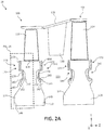
- Rotor disk 112 includes a cover plate 140 and retaining ring 180.
- Axially forward surface 146 of rotor disk 112 may include channel 152 with proximal flange 170 of cover plate 140 disposed within channel 152.
- Cover plate 140 may contact rotor disk 112 at an interface ridge 190 disposed at a radially outward location of channel 152.
- Cover plate 140 may fit in a radially inward position adjacent to interface ridge 190.
- Cover plate 140 and rotor disk 112 may form an interference fit at interface ridge 190.
- cover plate 140 may be held in place at interface ridge 190, and may further be held in place by retaining ring 180 and flange 160.
- Flange 160 of rotor disk 112 may be disposed at a radially inward location of channel 152, opposite to interface ridge 190.
- Proximal flange 170 may extend toward groove 162, and may not extend completely to or overlap radially with flange 160.
- Retaining ring 180 may be disposed between flange 160 and cover plate 140. Retaining ring 180 may form a point of contact for proximal flange 170 of cover plate 140, which may not reach flange 160.
- retaining ring 180 When installed, retaining ring 180 may extend radially outward from an axially aft surface 192 of flange 160 toward cover plate 140, thereby bridging a gap between cover plate 140 and flange 160.
- retaining ring 180 may include an annular shape or a split annular shape. Retaining ring 180 may be split for ease of insertion within groove 162. Retaining ring 180 may be positioned between flange 160 and cover plate 140. Retaining ring 180 may contact axially aft of surface 192 of flange 160 and may contact an axially forward surface 194 of cover plate 140. Retaining ring 180 may have an annular geometry with an outer surface 196 comprising a circular and circumferential contour such that outer surface 196 generally forms an annular ring. As a split ring, retaining ring 180 may comprise a discontinuous annular ring. Rotor disk 112 with flange 160, cover plate 140, and retaining ring 180 may comprise a retaining ring assembly 182 configured to retain cover plate 140 in a position with respect to rotor disk 112.
- retaining ring assembly 182 may comprise a first engine component 172 and a second engine component 174 including a retaining ring 180 disposed therebetween.
- the first engine component 172 and second engine component 174 may comprise any stationary or rotating engine components that include a retaining ring 180 disposed therebetween.
- the first engine component 172 may include cover plate 140 or 142 and the second engine component 174 may include rotor disk 112.
- retaining ring 180 may be a discontinuous annular ring, which is circumferentially discontinuous or split at an opening 200. Retaining ring 180 having a split may terminate at terminal edge 202 and a terminal edge 204, which define an opening 200 therebetween. Opening 200 may extend radially and completely through retaining ring 180. Opening 200 in retaining ring 180 may be defined by a terminal edge 202 and a terminal edge 204 of retaining ring 180. Retaining ring 180 may include an inner surface 206 opposite to outer surface 196.
- Inner surface 206 and/or outer surface 196 of retaining ring 180 may include a tapered, curved, rounded, and/or contoured surface geometry.
- Retaining ring 180 may include a first portion 208 having a flat geometry with a generally uniform thickness and may include a second portion 210 having a tapered, curved, rounded, and/or contoured geometry.
- Second portion 210 may comprise a terminal portion of retaining ring 180, and retaining ring 180 may include a second portion 210 disposed at each of terminal edges 202, 204.
- second portion 210 having a tapered, curved, rounded, and/or contoured geometry reduces stress in a first engine component 172, which may comprise cover plate 140.
- retaining ring 180 may be manufactured using forging, casting, additive manufacturing, machining or the like.
- the features of retaining ring 180, such as opening 200 and inner surface 206 geometry, may further be formed by milling, electrochemical machining (ECM), or electrical discharge machining (EDM) as desired, for example.
- retaining ring 180 may include a metal, such as titanium, titanium-based alloy, cobalt, cobalt-based alloys, nickel, nickel-based alloy, for example, austenitic nickel-chromium-based alloy such as INCONELTM which is available from Special Metals Corporation of New Hartford, New York, USA, aluminum, aluminum-based alloy, steel, or stainless steel, or other materials.
- retaining ring 180 may include a high performance nickel-based super alloy such as WASPALOYTM which is available from Special Metals Corporation of New Hartford, New York, USA.
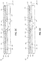
- second portion 210 of retaining ring 180 adjacent to or approaching terminal edges 202, 204 may include a linearly tapered geometry.
- a thickness of retaining ring 180 may be greater along a body of retaining ring 180, i.e. at first portion 208, than near terminal edges 202, 204 at second portion 210.
- the thickness of retaining ring 180 between outer surface 196 and inner surface 206 of first portion 208 may therefore be greater than the thickness between outer surface 196 and inner surface 206 of second portion 210.
- inner surface 206 of retaining ring 180 may be beveled or tapered at second portion 210, which may be a terminal portion.
- inner surface 206 may slope away from first engine component 172, such as cover plate 140, and taper toward terminal edge 202 as retaining ring 180 approaches terminal edge 202.
- axially forward surface 194 of cover plate 140 and inner surface 206 of retaining ring 180 may define a gap 212 between cover plate 140 and second portion 210 of retaining ring 180.
- Cover plate 140 may flex or deform into gap 212 and may contact second portion 210 of retaining ring 180.
- outer surface 196 of retaining ring 180 may be beveled or tapered at second portion 210, which may be a terminal portion.
- inner surface 206 may slope away from a second engine component 174, such as flange 160, and taper toward terminal edge 202 as retaining ring 180 approaches terminal edge 202.
- Axially aft surface 192 of flange 160 and outer surface 196 of retaining ring 180 may define a gap 214 between cover plate 140 and second portion 210 of retaining ring 180.
- Cover plate 140 may flex or deform towards retaining ring 180, which may flex or deform retaining ring 180 into gap 214, and outer surface 196 of second portion 210 of retaining ring 180 may contact flange 160.
- each of second portions 210 may taper or slope away from or towards first engine component 172, such as cover plate 140. In various embodiments, each of second portions 210 may taper or slope away from or towards second engine component 174, such as flange 160.
- the tapered geometry of second portions 210 near terminal edges 202, 204 may decrease the mechanical stress on cover plate 140 at each of areas 220, 222. Areas 220, 222 represent portions of cover plate 140 adjacent to the transition points where retaining ring 180 terminates and opening 200 begins.
- the tapered geometry of retaining ring 180 may create a smoother transition than an abrupt or 90 degree transition between a body of retaining ring 180 and opening 200 between terminal edges 202, 204 of retaining ring 180.
- the tapered geometry of retaining ring 180 may decrease mechanical stress in cover plate 140 and may increase the operational capability of cover plate 140.
- second portion 210 of retaining ring 180 adjacent to or approaching terminal edges 202, 204 may include a curvedly tapered geometry.
- Second portion 210 may include a curved inner surface 206 sloping away from a first engine component 172, which may comprise cover plate 140. Cover plate 140 may flex or deform into gap 212 and may contact second portion 210 of retaining ring 180.
- Second portion 210 may include a curved outer surface 196 sloping toward cover plate 140.
- Cover plate 140 may flex or deform towards retaining ring 180, which may flex or deform retaining ring 180 into gap 214, and outer surface 196 of second portion 210 of retaining ring 180 may contact a second engine component 174, such as flange 160.
- the tapered geometry of second portions 210 near terminal edges 202, 204 may decrease the mechanical stress on cover plate 140 at each of areas 220, 222.
- a retaining ring assembly 186 having a retaining ring 180 with a contoured terminal portion is shown in accordance with various embodiments.
- Retaining ring 180 may include a first portion 208 having a flat geometry with a generally uniform thickness and may include a second portion 210 having a rounded, and/or contoured geometry.
- Second portion 210 may comprise a terminal portion of retaining ring 180 and may comprise terminal edges 202, 204, which may be rounded or contoured.
- Retaining ring 180 may include opening 200 defined by terminal edge 202 and terminal edge 204 of retaining ring 180.
- Cover plate 140 may flex or deform into opening 200.
- the contoured geometry of terminal edges 202, 204 may decrease the mechanical stress on cover plate 140 at each of areas 220, 222.
- a retaining ring assembly 188 having a retaining ring 180 with a tapered and contoured terminal portion is shown in accordance with various embodiments.
- Retaining ring 180 may include a first portion 208 having a flat geometry with a generally uniform thickness and may include a second portion 210 having a tapered and contoured geometry.
- Second portion 210 of retaining ring 180 adjacent to or approaching terminal edges 202, 204 may include a linearly tapered geometry and terminal edges 202, 204 may include a rounded and/or contoured geometry.
- each of second portions 210 may taper or slope away from or towards a first engine component 172, which may comprise cover plate 140.
- Second portion 210 of retaining ring 180 may include an inner surface 206 sloping away from cover plate 140. Cover plate 140 may flex or deform into gap 212 and may contact second portion 210 of retaining ring 180 upon flexing into gap 212. Second portion 210 may include an outer surface 196 sloping toward cover plate 140. Cover plate 140 may flex or deform towards retaining ring 180, which may flex or deform retaining ring 180 into gap 214, and outer surface 196 of second portion 210 of retaining ring 180 may contact flange 160 upon flexing into gap 214. Second portion 210 may further comprise terminal edges 202, 204 which are rounded or contoured. The tapered geometry of second portions 210 near terminal edges 202, 204 and the contoured geometry of terminal edges 202, 204 may decrease the mechanical stress on cover plate 140 at each of areas 220, 222.
- retaining ring 180 coupled to rotor disk 112 and cover plate 140
- the systems and methods described herein are applicable to many types of retaining rings used with any rotating or stationary part.
- a split retaining ring having a tapered, curved, rounded, and/or contoured terminal end may be used, for example, with a gas path seal or for retaining a stationary component with respect to an engine case. Therefore, the disclosure herein is not limited to applications solely directed to retaining ring 180 coupled to cover plates 140, 142.
- references to "various embodiments”, “one embodiment”, “an embodiment”, “an example embodiment”, etc. indicate that the embodiment described may include a particular feature, structure, or characteristic, but every embodiment may not necessarily include the particular feature, structure, or characteristic. Moreover, such phrases are not necessarily referring to the same embodiment. Further, when a particular feature, structure, or characteristic is described in connection with an embodiment, it is submitted that it is within the knowledge of one skilled in the art to affect such feature, structure, or characteristic in connection with other embodiments whether or not explicitly described. After reading the description, it will be apparent to one skilled in the relevant art(s) how to implement the disclosure in alternative embodiments.
Landscapes
- Engineering & Computer Science (AREA)
- Mechanical Engineering (AREA)
- General Engineering & Computer Science (AREA)
- Structures Of Non-Positive Displacement Pumps (AREA)
- Turbine Rotor Nozzle Sealing (AREA)
Applications Claiming Priority (1)
| Application Number | Priority Date | Filing Date | Title |
|---|---|---|---|
| US15/154,351 US10215037B2 (en) | 2016-05-13 | 2016-05-13 | Contoured retaining ring |
Publications (4)
| Publication Number | Publication Date |
|---|---|
| EP3244014A2 true EP3244014A2 (fr) | 2017-11-15 |
| EP3244014A3 EP3244014A3 (fr) | 2017-12-27 |
| EP3244014B1 EP3244014B1 (fr) | 2021-01-20 |
| EP3244014B8 EP3244014B8 (fr) | 2021-03-31 |
Family
ID=58213033
Family Applications (1)
| Application Number | Title | Priority Date | Filing Date |
|---|---|---|---|
| EP17158977.3A Active EP3244014B8 (fr) | 2016-05-13 | 2017-03-02 | Ensemble de bague de retenue pour moteur à turbine à gaz |
Country Status (2)
| Country | Link |
|---|---|
| US (1) | US10215037B2 (fr) |
| EP (1) | EP3244014B8 (fr) |
Cited By (1)
| Publication number | Priority date | Publication date | Assignee | Title |
|---|---|---|---|---|
| GB2584097A (en) * | 2019-05-20 | 2020-11-25 | Cross Mfg 1938 Limited | Ring fastener |
Families Citing this family (3)
| Publication number | Priority date | Publication date | Assignee | Title |
|---|---|---|---|---|
| US11168615B1 (en) | 2020-08-25 | 2021-11-09 | Raytheon Technologies Corporation | Double ring axial sealing design |
| US11686202B1 (en) * | 2021-12-20 | 2023-06-27 | Rolls-Royce North American Technologies Inc. | Rotor damper with contact biasing feature for turbine engines |
| GB202400108D0 (en) * | 2024-01-04 | 2024-02-21 | Rolls Royce Plc | A rotor stage for a gas turbine engine |
Family Cites Families (23)
| Publication number | Priority date | Publication date | Assignee | Title |
|---|---|---|---|---|
| US1638209A (en) * | 1925-10-01 | 1927-08-09 | Niebuhr William Charles | Separable ring |
| US4343581A (en) * | 1979-05-21 | 1982-08-10 | Waldes Kohinoor, Inc. | Double-bevel spring retaining ring |
| US4752178A (en) * | 1986-12-17 | 1988-06-21 | Smalley Steel Ring Company | Waved retaining ring |
| US4767276A (en) * | 1986-12-19 | 1988-08-30 | General Electric Company | Retainer ring |
| FR2695433B1 (fr) * | 1992-09-09 | 1994-10-21 | Snecma | Joint annulaire d'étanchéité disposé à une extrémité axiale d'un rotor et recouvrant des brochages d'aubes. |
| US5281098A (en) | 1992-10-28 | 1994-01-25 | General Electric Company | Single ring blade retaining assembly |
| US5338154A (en) | 1993-03-17 | 1994-08-16 | General Electric Company | Turbine disk interstage seal axial retaining ring |
| FR2812906B1 (fr) | 2000-08-10 | 2002-09-20 | Snecma Moteurs | Bague de retention axiale d'un flasque sur un disque |
| FR2857691B1 (fr) * | 2003-07-17 | 2006-02-03 | Snecma Moteurs | Retention de flasque de rotor |
| DE102005048198B4 (de) * | 2005-10-07 | 2007-06-06 | Albrecht Knecht | Sprengring |
| FR2913718B1 (fr) * | 2007-03-15 | 2009-06-05 | Snecma Propulsion Solide Sa | Ensemble d'anneau de turbine pour turbine a gaz |
| FR2935428B1 (fr) * | 2008-08-26 | 2015-06-26 | Snecma | Aubage fixe de turbomachine a masse reduite et turbomachine comportant au moins un tel aubage fixe |
| US8491267B2 (en) | 2010-08-27 | 2013-07-23 | Pratt & Whitney Canada Corp. | Retaining ring arrangement for a rotary assembly |
| DE102011082493A1 (de) * | 2011-09-12 | 2013-03-14 | Rolls-Royce Deutschland Ltd & Co Kg | Sicherungssegment zur Schwingungsdämpfung von Turbinenlauf-schaufeln und Rotorvorrichtung |
| US20130323052A1 (en) * | 2012-05-31 | 2013-12-05 | Solar Turbines Inc. | Retaining ring |
| US9790803B2 (en) | 2013-03-08 | 2017-10-17 | United Technologies Corporation | Double split blade lock ring |
| US9567857B2 (en) | 2013-03-08 | 2017-02-14 | Rolls-Royce North American Technologies, Inc. | Turbine split ring retention and anti-rotation method |
| US10247003B2 (en) | 2013-09-26 | 2019-04-02 | United Technologies Corporation | Balanced rotating component for a gas powered engine |
| DE102013223133B3 (de) * | 2013-11-13 | 2014-10-30 | Intellectual Property Management MTU Aero Engines AG | Gasturbine |
| GB201404362D0 (en) * | 2014-03-12 | 2014-04-23 | Rolls Royce Plc | Bladed rotor |
| US10415401B2 (en) * | 2016-09-08 | 2019-09-17 | United Technologies Corporation | Airfoil retention assembly for a gas turbine engine |
| US10392966B2 (en) * | 2016-09-23 | 2019-08-27 | United Technologies Corporation | Retaining ring end gap features |
| US10378588B2 (en) * | 2017-01-19 | 2019-08-13 | Gkn Automotive Limited | Retainer for rotating members |
-
2016
- 2016-05-13 US US15/154,351 patent/US10215037B2/en active Active
-
2017
- 2017-03-02 EP EP17158977.3A patent/EP3244014B8/fr active Active
Non-Patent Citations (1)
| Title |
|---|
| None |
Cited By (4)
| Publication number | Priority date | Publication date | Assignee | Title |
|---|---|---|---|---|
| GB2584097A (en) * | 2019-05-20 | 2020-11-25 | Cross Mfg 1938 Limited | Ring fastener |
| GB2584171A (en) * | 2019-05-20 | 2020-11-25 | Cross Mfg Company 1938 Limited | Ring fastener |
| GB2584171B (en) * | 2019-05-20 | 2021-06-16 | Cross Mfg Company 1938 Limited | Ring fastener |
| US11512603B2 (en) | 2019-05-20 | 2022-11-29 | Cross Manufacturing Company (1938) Limited | Ring fastener |
Also Published As
| Publication number | Publication date |
|---|---|
| US20170328224A1 (en) | 2017-11-16 |
| EP3244014A3 (fr) | 2017-12-27 |
| US10215037B2 (en) | 2019-02-26 |
| EP3244014B1 (fr) | 2021-01-20 |
| EP3244014B8 (fr) | 2021-03-31 |
Similar Documents
| Publication | Publication Date | Title |
|---|---|---|
| EP3404214B1 (fr) | Agencement de joint de pointe d'aubes et moteur à turbine à gaz ayant un tel agencement | |
| EP3351740A1 (fr) | Section d'une turbine à gaz comprenant un joint d'étanchéité segmenté à l'air extérieur d'aubes | |
| EP3112599B1 (fr) | Tube de transfert et section de turbine avec tube de transfert | |
| EP2604813A2 (fr) | Pièce de retenue de moteur à turbine à gaz | |
| US10018066B2 (en) | Mini blind stator leakage reduction | |
| US20110243725A1 (en) | Turbine shroud mounting apparatus with anti-rotation feature | |
| EP3244014B1 (fr) | Ensemble de bague de retenue pour moteur à turbine à gaz | |
| EP3477047B1 (fr) | Liaisons structurelles segmentées pour accord de fréquence de disque et moteur à turbine à gaz associé ayant telles liaisons | |
| EP3296515B1 (fr) | Ensemble d'aubes de stator comprenant un plug anti-rotation | |
| EP3112615A1 (fr) | Aube de stator en porte-à-faux et un ensemble stator pour une machine rotative | |
| EP3081748B1 (fr) | Système de turbine à gaz ayant une bague d'étanchéité | |
| EP3037627B1 (fr) | Géométrie matérielle permettant d'augmenter le chevauchement de pièce et de maintien du jeu | |
| EP3553278B1 (fr) | Nervures de renfort axial/ailettes d'augmentation | |
| US11111804B2 (en) | Inserts for slotted integrally bladed rotor | |
| EP3498983B1 (fr) | Joint à brosse comprenant une plaque de support à ressort | |
| EP3051067A1 (fr) | Entrée aérodynamique tronquée de moteur à turbine à gaz | |
| EP3098387B1 (fr) | Amortisseur à tolérance de pannes d'installation | |
| EP3663538B1 (fr) | Ensemble de protection contre la survitesse d'un rotor | |
| US11352892B2 (en) | Seal element for sealing a joint between a rotor blade and a rotor disk | |
| EP3957824B1 (fr) | Dispositif tandem de disque de rotor et moteur à turbine à gaz associé | |
| EP3101228B1 (fr) | Déflecteur de division d'écoulement | |
| EP3470685A1 (fr) | Revêtement d'usure de fermeture d'espace | |
| EP3101232A1 (fr) | Disque rotorique, agencement et moteur à turbine à gaz associés | |
| EP3415716B1 (fr) | Refroidissement des extrémités des aubes de turbine |
Legal Events
| Date | Code | Title | Description |
|---|---|---|---|
| PUAI | Public reference made under article 153(3) epc to a published international application that has entered the european phase |
Free format text: ORIGINAL CODE: 0009012 |
|
| STAA | Information on the status of an ep patent application or granted ep patent |
Free format text: STATUS: THE APPLICATION HAS BEEN PUBLISHED |
|
| AK | Designated contracting states |
Kind code of ref document: A2 Designated state(s): AL AT BE BG CH CY CZ DE DK EE ES FI FR GB GR HR HU IE IS IT LI LT LU LV MC MK MT NL NO PL PT RO RS SE SI SK SM TR |
|
| AX | Request for extension of the european patent |
Extension state: BA ME |
|
| PUAL | Search report despatched |
Free format text: ORIGINAL CODE: 0009013 |
|
| AK | Designated contracting states |
Kind code of ref document: A3 Designated state(s): AL AT BE BG CH CY CZ DE DK EE ES FI FR GB GR HR HU IE IS IT LI LT LU LV MC MK MT NL NO PL PT RO RS SE SI SK SM TR |
|
| AX | Request for extension of the european patent |
Extension state: BA ME |
|
| RIC1 | Information provided on ipc code assigned before grant |
Ipc: F01D 5/30 20060101AFI20171117BHEP |
|
| STAA | Information on the status of an ep patent application or granted ep patent |
Free format text: STATUS: REQUEST FOR EXAMINATION WAS MADE |
|
| 17P | Request for examination filed |
Effective date: 20180627 |
|
| RBV | Designated contracting states (corrected) |
Designated state(s): AL AT BE BG CH CY CZ DE DK EE ES FI FR GB GR HR HU IE IS IT LI LT LU LV MC MK MT NL NO PL PT RO RS SE SI SK SM TR |
|
| STAA | Information on the status of an ep patent application or granted ep patent |
Free format text: STATUS: EXAMINATION IS IN PROGRESS |
|
| 17Q | First examination report despatched |
Effective date: 20181127 |
|
| GRAP | Despatch of communication of intention to grant a patent |
Free format text: ORIGINAL CODE: EPIDOSNIGR1 |
|
| STAA | Information on the status of an ep patent application or granted ep patent |
Free format text: STATUS: GRANT OF PATENT IS INTENDED |
|
| INTG | Intention to grant announced |
Effective date: 20200914 |
|
| GRAS | Grant fee paid |
Free format text: ORIGINAL CODE: EPIDOSNIGR3 |
|
| GRAA | (expected) grant |
Free format text: ORIGINAL CODE: 0009210 |
|
| STAA | Information on the status of an ep patent application or granted ep patent |
Free format text: STATUS: THE PATENT HAS BEEN GRANTED |
|
| AK | Designated contracting states |
Kind code of ref document: B1 Designated state(s): AL AT BE BG CH CY CZ DE DK EE ES FI FR GB GR HR HU IE IS IT LI LT LU LV MC MK MT NL NO PL PT RO RS SE SI SK SM TR |
|
| REG | Reference to a national code |
Ref country code: GB Ref legal event code: FG4D |
|
| REG | Reference to a national code |
Ref country code: CH Ref legal event code: EP |
|
| REG | Reference to a national code |
Ref country code: DE Ref legal event code: R096 Ref document number: 602017031553 Country of ref document: DE |
|
| REG | Reference to a national code |
Ref country code: AT Ref legal event code: REF Ref document number: 1356569 Country of ref document: AT Kind code of ref document: T Effective date: 20210215 |
|
| REG | Reference to a national code |
Ref country code: IE Ref legal event code: FG4D |
|
| REG | Reference to a national code |
Ref country code: DE Ref legal event code: R081 Ref document number: 602017031553 Country of ref document: DE Owner name: RAYTHEON TECHNOLOGIES CORPORATION, FARMINGTON, US Free format text: FORMER OWNER: UNITED TECHNOLOGIES CORPORATION, FARMINGTON, CONN., US Ref country code: DE Ref legal event code: R081 Ref document number: 602017031553 Country of ref document: DE Owner name: RTX CORPORATION (N.D.GES.D. STAATES DELAWARE),, US Free format text: FORMER OWNER: UNITED TECHNOLOGIES CORPORATION, FARMINGTON, CONN., US |
|
| REG | Reference to a national code |
Ref country code: CH Ref legal event code: PK Free format text: BERICHTIGUNG B8 |
|
| RAP2 | Party data changed (patent owner data changed or rights of a patent transferred) |
Owner name: RAYTHEON TECHNOLOGIES CORPORATION |
|
| REG | Reference to a national code |
Ref country code: NL Ref legal event code: MP Effective date: 20210120 |
|
| REG | Reference to a national code |
Ref country code: LT Ref legal event code: MG9D |
|
| REG | Reference to a national code |
Ref country code: AT Ref legal event code: MK05 Ref document number: 1356569 Country of ref document: AT Kind code of ref document: T Effective date: 20210120 |
|
| PG25 | Lapsed in a contracting state [announced via postgrant information from national office to epo] |
Ref country code: PT Free format text: LAPSE BECAUSE OF FAILURE TO SUBMIT A TRANSLATION OF THE DESCRIPTION OR TO PAY THE FEE WITHIN THE PRESCRIBED TIME-LIMIT Effective date: 20210520 Ref country code: NO Free format text: LAPSE BECAUSE OF FAILURE TO SUBMIT A TRANSLATION OF THE DESCRIPTION OR TO PAY THE FEE WITHIN THE PRESCRIBED TIME-LIMIT Effective date: 20210420 Ref country code: HR Free format text: LAPSE BECAUSE OF FAILURE TO SUBMIT A TRANSLATION OF THE DESCRIPTION OR TO PAY THE FEE WITHIN THE PRESCRIBED TIME-LIMIT Effective date: 20210120 Ref country code: GR Free format text: LAPSE BECAUSE OF FAILURE TO SUBMIT A TRANSLATION OF THE DESCRIPTION OR TO PAY THE FEE WITHIN THE PRESCRIBED TIME-LIMIT Effective date: 20210421 Ref country code: FI Free format text: LAPSE BECAUSE OF FAILURE TO SUBMIT A TRANSLATION OF THE DESCRIPTION OR TO PAY THE FEE WITHIN THE PRESCRIBED TIME-LIMIT Effective date: 20210120 Ref country code: BG Free format text: LAPSE BECAUSE OF FAILURE TO SUBMIT A TRANSLATION OF THE DESCRIPTION OR TO PAY THE FEE WITHIN THE PRESCRIBED TIME-LIMIT Effective date: 20210420 Ref country code: LT Free format text: LAPSE BECAUSE OF FAILURE TO SUBMIT A TRANSLATION OF THE DESCRIPTION OR TO PAY THE FEE WITHIN THE PRESCRIBED TIME-LIMIT Effective date: 20210120 |
|
| PG25 | Lapsed in a contracting state [announced via postgrant information from national office to epo] |
Ref country code: RS Free format text: LAPSE BECAUSE OF FAILURE TO SUBMIT A TRANSLATION OF THE DESCRIPTION OR TO PAY THE FEE WITHIN THE PRESCRIBED TIME-LIMIT Effective date: 20210120 Ref country code: PL Free format text: LAPSE BECAUSE OF FAILURE TO SUBMIT A TRANSLATION OF THE DESCRIPTION OR TO PAY THE FEE WITHIN THE PRESCRIBED TIME-LIMIT Effective date: 20210120 Ref country code: LV Free format text: LAPSE BECAUSE OF FAILURE TO SUBMIT A TRANSLATION OF THE DESCRIPTION OR TO PAY THE FEE WITHIN THE PRESCRIBED TIME-LIMIT Effective date: 20210120 Ref country code: AT Free format text: LAPSE BECAUSE OF FAILURE TO SUBMIT A TRANSLATION OF THE DESCRIPTION OR TO PAY THE FEE WITHIN THE PRESCRIBED TIME-LIMIT Effective date: 20210120 Ref country code: SE Free format text: LAPSE BECAUSE OF FAILURE TO SUBMIT A TRANSLATION OF THE DESCRIPTION OR TO PAY THE FEE WITHIN THE PRESCRIBED TIME-LIMIT Effective date: 20210120 |
|
| PG25 | Lapsed in a contracting state [announced via postgrant information from national office to epo] |
Ref country code: IS Free format text: LAPSE BECAUSE OF FAILURE TO SUBMIT A TRANSLATION OF THE DESCRIPTION OR TO PAY THE FEE WITHIN THE PRESCRIBED TIME-LIMIT Effective date: 20210520 |
|
| REG | Reference to a national code |
Ref country code: DE Ref legal event code: R097 Ref document number: 602017031553 Country of ref document: DE |
|
| PG25 | Lapsed in a contracting state [announced via postgrant information from national office to epo] |
Ref country code: SM Free format text: LAPSE BECAUSE OF FAILURE TO SUBMIT A TRANSLATION OF THE DESCRIPTION OR TO PAY THE FEE WITHIN THE PRESCRIBED TIME-LIMIT Effective date: 20210120 Ref country code: CZ Free format text: LAPSE BECAUSE OF FAILURE TO SUBMIT A TRANSLATION OF THE DESCRIPTION OR TO PAY THE FEE WITHIN THE PRESCRIBED TIME-LIMIT Effective date: 20210120 Ref country code: EE Free format text: LAPSE BECAUSE OF FAILURE TO SUBMIT A TRANSLATION OF THE DESCRIPTION OR TO PAY THE FEE WITHIN THE PRESCRIBED TIME-LIMIT Effective date: 20210120 Ref country code: MC Free format text: LAPSE BECAUSE OF FAILURE TO SUBMIT A TRANSLATION OF THE DESCRIPTION OR TO PAY THE FEE WITHIN THE PRESCRIBED TIME-LIMIT Effective date: 20210120 |
|
| REG | Reference to a national code |
Ref country code: CH Ref legal event code: PL |
|
| PLBE | No opposition filed within time limit |
Free format text: ORIGINAL CODE: 0009261 |
|
| STAA | Information on the status of an ep patent application or granted ep patent |
Free format text: STATUS: NO OPPOSITION FILED WITHIN TIME LIMIT |
|
| PG25 | Lapsed in a contracting state [announced via postgrant information from national office to epo] |
Ref country code: DK Free format text: LAPSE BECAUSE OF FAILURE TO SUBMIT A TRANSLATION OF THE DESCRIPTION OR TO PAY THE FEE WITHIN THE PRESCRIBED TIME-LIMIT Effective date: 20210120 Ref country code: SK Free format text: LAPSE BECAUSE OF FAILURE TO SUBMIT A TRANSLATION OF THE DESCRIPTION OR TO PAY THE FEE WITHIN THE PRESCRIBED TIME-LIMIT Effective date: 20210120 Ref country code: RO Free format text: LAPSE BECAUSE OF FAILURE TO SUBMIT A TRANSLATION OF THE DESCRIPTION OR TO PAY THE FEE WITHIN THE PRESCRIBED TIME-LIMIT Effective date: 20210120 |
|
| REG | Reference to a national code |
Ref country code: BE Ref legal event code: MM Effective date: 20210331 |
|
| 26N | No opposition filed |
Effective date: 20211021 |
|
| PG25 | Lapsed in a contracting state [announced via postgrant information from national office to epo] |
Ref country code: ES Free format text: LAPSE BECAUSE OF FAILURE TO SUBMIT A TRANSLATION OF THE DESCRIPTION OR TO PAY THE FEE WITHIN THE PRESCRIBED TIME-LIMIT Effective date: 20210120 Ref country code: IE Free format text: LAPSE BECAUSE OF NON-PAYMENT OF DUE FEES Effective date: 20210302 Ref country code: LU Free format text: LAPSE BECAUSE OF NON-PAYMENT OF DUE FEES Effective date: 20210302 Ref country code: LI Free format text: LAPSE BECAUSE OF NON-PAYMENT OF DUE FEES Effective date: 20210331 Ref country code: CH Free format text: LAPSE BECAUSE OF NON-PAYMENT OF DUE FEES Effective date: 20210331 Ref country code: AL Free format text: LAPSE BECAUSE OF FAILURE TO SUBMIT A TRANSLATION OF THE DESCRIPTION OR TO PAY THE FEE WITHIN THE PRESCRIBED TIME-LIMIT Effective date: 20210120 |
|
| PG25 | Lapsed in a contracting state [announced via postgrant information from national office to epo] |
Ref country code: SI Free format text: LAPSE BECAUSE OF FAILURE TO SUBMIT A TRANSLATION OF THE DESCRIPTION OR TO PAY THE FEE WITHIN THE PRESCRIBED TIME-LIMIT Effective date: 20210120 |
|
| PG25 | Lapsed in a contracting state [announced via postgrant information from national office to epo] |
Ref country code: IT Free format text: LAPSE BECAUSE OF FAILURE TO SUBMIT A TRANSLATION OF THE DESCRIPTION OR TO PAY THE FEE WITHIN THE PRESCRIBED TIME-LIMIT Effective date: 20210120 |
|
| PG25 | Lapsed in a contracting state [announced via postgrant information from national office to epo] |
Ref country code: IS Free format text: LAPSE BECAUSE OF FAILURE TO SUBMIT A TRANSLATION OF THE DESCRIPTION OR TO PAY THE FEE WITHIN THE PRESCRIBED TIME-LIMIT Effective date: 20210520 |
|
| PG25 | Lapsed in a contracting state [announced via postgrant information from national office to epo] |
Ref country code: BE Free format text: LAPSE BECAUSE OF NON-PAYMENT OF DUE FEES Effective date: 20210331 |
|
| PG25 | Lapsed in a contracting state [announced via postgrant information from national office to epo] |
Ref country code: HU Free format text: LAPSE BECAUSE OF FAILURE TO SUBMIT A TRANSLATION OF THE DESCRIPTION OR TO PAY THE FEE WITHIN THE PRESCRIBED TIME-LIMIT; INVALID AB INITIO Effective date: 20170302 |
|
| P01 | Opt-out of the competence of the unified patent court (upc) registered |
Effective date: 20230520 |
|
| PG25 | Lapsed in a contracting state [announced via postgrant information from national office to epo] |
Ref country code: NL Free format text: LAPSE BECAUSE OF NON-PAYMENT OF DUE FEES Effective date: 20210120 Ref country code: CY Free format text: LAPSE BECAUSE OF FAILURE TO SUBMIT A TRANSLATION OF THE DESCRIPTION OR TO PAY THE FEE WITHIN THE PRESCRIBED TIME-LIMIT Effective date: 20210120 |
|
| PG25 | Lapsed in a contracting state [announced via postgrant information from national office to epo] |
Ref country code: MK Free format text: LAPSE BECAUSE OF FAILURE TO SUBMIT A TRANSLATION OF THE DESCRIPTION OR TO PAY THE FEE WITHIN THE PRESCRIBED TIME-LIMIT Effective date: 20210120 |
|
| PG25 | Lapsed in a contracting state [announced via postgrant information from national office to epo] |
Ref country code: TR Free format text: LAPSE BECAUSE OF FAILURE TO SUBMIT A TRANSLATION OF THE DESCRIPTION OR TO PAY THE FEE WITHIN THE PRESCRIBED TIME-LIMIT Effective date: 20210120 |
|
| PG25 | Lapsed in a contracting state [announced via postgrant information from national office to epo] |
Ref country code: MT Free format text: LAPSE BECAUSE OF FAILURE TO SUBMIT A TRANSLATION OF THE DESCRIPTION OR TO PAY THE FEE WITHIN THE PRESCRIBED TIME-LIMIT Effective date: 20210120 |
|
| REG | Reference to a national code |
Ref country code: DE Ref legal event code: R081 Ref document number: 602017031553 Country of ref document: DE Owner name: RTX CORPORATION (N.D.GES.D. STAATES DELAWARE),, US Free format text: FORMER OWNER: RAYTHEON TECHNOLOGIES CORPORATION, FARMINGTON, CT, US |
|
| PGFP | Annual fee paid to national office [announced via postgrant information from national office to epo] |
Ref country code: GB Payment date: 20260219 Year of fee payment: 10 |
|
| PGFP | Annual fee paid to national office [announced via postgrant information from national office to epo] |
Ref country code: DE Payment date: 20260219 Year of fee payment: 10 |
|
| PGFP | Annual fee paid to national office [announced via postgrant information from national office to epo] |
Ref country code: FR Payment date: 20260219 Year of fee payment: 10 |