EP3244017B1 - Statorabschnitt für ein gasturbinentriebwerk und zugehöriges verfahren zum einsetzen einer verschleissauskleidung innerhalb eines gasturbinentriebwerks - Google Patents
Statorabschnitt für ein gasturbinentriebwerk und zugehöriges verfahren zum einsetzen einer verschleissauskleidung innerhalb eines gasturbinentriebwerks Download PDFInfo
- Publication number
- EP3244017B1 EP3244017B1 EP17157173.0A EP17157173A EP3244017B1 EP 3244017 B1 EP3244017 B1 EP 3244017B1 EP 17157173 A EP17157173 A EP 17157173A EP 3244017 B1 EP3244017 B1 EP 3244017B1
- Authority
- EP
- European Patent Office
- Prior art keywords
- wear liner
- hook
- component
- gas turbine
- turbine engine
- Prior art date
- Legal status (The legal status is an assumption and is not a legal conclusion. Google has not performed a legal analysis and makes no representation as to the accuracy of the status listed.)
- Active
Links
Images




Classifications
-
- F—MECHANICAL ENGINEERING; LIGHTING; HEATING; WEAPONS; BLASTING
- F01—MACHINES OR ENGINES IN GENERAL; ENGINE PLANTS IN GENERAL; STEAM ENGINES
- F01D—NON-POSITIVE DISPLACEMENT MACHINES OR ENGINES, e.g. STEAM TURBINES
- F01D25/00—Component parts, details, or accessories, not provided for in, or of interest apart from, other groups
- F01D25/007—Preventing corrosion
-
- F—MECHANICAL ENGINEERING; LIGHTING; HEATING; WEAPONS; BLASTING
- F01—MACHINES OR ENGINES IN GENERAL; ENGINE PLANTS IN GENERAL; STEAM ENGINES
- F01D—NON-POSITIVE DISPLACEMENT MACHINES OR ENGINES, e.g. STEAM TURBINES
- F01D25/00—Component parts, details, or accessories, not provided for in, or of interest apart from, other groups
- F01D25/24—Casings; Casing parts, e.g. diaphragms, casing fastenings
- F01D25/246—Fastening of diaphragms or stator-rings
-
- F—MECHANICAL ENGINEERING; LIGHTING; HEATING; WEAPONS; BLASTING
- F01—MACHINES OR ENGINES IN GENERAL; ENGINE PLANTS IN GENERAL; STEAM ENGINES
- F01D—NON-POSITIVE DISPLACEMENT MACHINES OR ENGINES, e.g. STEAM TURBINES
- F01D9/00—Stators
- F01D9/02—Nozzles; Nozzle boxes; Stator blades; Guide conduits, e.g. individual nozzles
- F01D9/04—Nozzles; Nozzle boxes; Stator blades; Guide conduits, e.g. individual nozzles forming ring or sector
- F01D9/042—Nozzles; Nozzle boxes; Stator blades; Guide conduits, e.g. individual nozzles forming ring or sector fixing blades to stators
-
- F—MECHANICAL ENGINEERING; LIGHTING; HEATING; WEAPONS; BLASTING
- F01—MACHINES OR ENGINES IN GENERAL; ENGINE PLANTS IN GENERAL; STEAM ENGINES
- F01D—NON-POSITIVE DISPLACEMENT MACHINES OR ENGINES, e.g. STEAM TURBINES
- F01D11/00—Preventing or minimising internal leakage of working-fluid, e.g. between stages
- F01D11/005—Sealing means between non relatively rotating elements
-
- F—MECHANICAL ENGINEERING; LIGHTING; HEATING; WEAPONS; BLASTING
- F05—INDEXING SCHEMES RELATING TO ENGINES OR PUMPS IN VARIOUS SUBCLASSES OF CLASSES F01-F04
- F05D—INDEXING SCHEME FOR ASPECTS RELATING TO NON-POSITIVE-DISPLACEMENT MACHINES OR ENGINES, GAS-TURBINES OR JET-PROPULSION PLANTS
- F05D2250/00—Geometry
- F05D2250/70—Shape
- F05D2250/75—Shape given by its similarity to a letter, e.g. T-shaped
-
- F—MECHANICAL ENGINEERING; LIGHTING; HEATING; WEAPONS; BLASTING
- F05—INDEXING SCHEMES RELATING TO ENGINES OR PUMPS IN VARIOUS SUBCLASSES OF CLASSES F01-F04
- F05D—INDEXING SCHEME FOR ASPECTS RELATING TO NON-POSITIVE-DISPLACEMENT MACHINES OR ENGINES, GAS-TURBINES OR JET-PROPULSION PLANTS
- F05D2260/00—Function
- F05D2260/95—Preventing corrosion
Definitions
- the present invention prelates to a stator section for a gas turbine engine and to a method of installing a wear liner within a gas turbine engine.
- a gas turbine engine typically includes a fan, a compressor, a combustor and a turbine.
- Stator airfoils are supported on features defined within an inner case.
- the features typically include grooves or slots that receive flanges known as feet or hooks.
- the fit of the feet within the grooves of the inner case are typically a clearance fit that accommodates relative thermal growth during operation. The relative movement can cause wear as well as provide an undesired leak path. The tight tolerances make assembly and manufacture difficult while also increasing costs.
- US 2012/128481 A1 discloses a prior art anti-wear device for the blades of a turbine distributor in an aeronautical turbine engine.
- US 2008/053107 A1 discloses a prior art slidable spring-loaded transition-to-turbine seal apparatus and heat-shielding system, comprising the seal, at a transition/turbine junction of a gas turbine engine.
- GB 2477825 A discloses a prior art anti fret liner assembly.
- EP 2 612 998 A2 discloses a prior art stator vane integrated attachment liner and spring damper.
- stator section for a gas turbine engine as recited in claim 1.
- systems and methods may find particular use in connection with a half wear liner that protects the inside surface of a fan case.
- FIGS. 1-4 An X-Y-Z coordinate system is shown in FIGS. 1-4 for spatial reference purposes, with the orthogonal X and Y-axes defining a horizontal X-Y plane to which the Z-axis is perpendicular.
- the term "vertically extending” includes exactly vertical (i.e., exactly parallel to the Z-axis) and approximately vertical (i.e., approximately parallel to the Z-axis), while the term “horizontally extending” includes exactly horizontal (i.e., exactly parallel to the X-Y plane) and approximately horizontal (i.e., approximately parallel to the X-Y plane).
- FIG. 1 schematically illustrates an example gas turbine engine 100 that includes a fan 102, a compressor 104, a combustor 106 and a turbine 108.
- Alternative engines might include an augmenter (not shown) among other systems or features.
- the fan 102 drives air along a bypass flow path B while the compressor 104 draws air in along a core flow path C where air is compressed and communicated to a combustor 106.
- the combustor 106 air is mixed with fuel and ignited to generate a high-pressure exhaust gas stream that expands through the turbine 108 where energy is extracted and utilized to drive the fan 102 and the compressor 104.
- turbofan gas turbine engine Although the disclosed embodiments frequently depict a turbofan gas turbine engine, it should be understood that the concepts described herein are not limited to use with turbofans.
- the example gas turbine engine 100 generally includes a low-speed spool 110 and a high-speed spool 112 mounted for rotation about an engine central longitudinal axis A relative to an engine static structure 116 via bearing systems 118. It should be understood that bearing systems 118 at various locations may alternatively or additionally be provided.
- the low-speed spool 110 generally includes an inner shaft 120 that connects a fan 122 and a low-pressure compressor 124 to a low-pressure turbine 126.
- the inner shaft 120 drives the fan 122 through a speed change device, such as a geared architecture 128, to drive the fan 122 at a lower speed than the low-speed spool 110.
- the high-speed spool 112 includes an outer shaft 130 that interconnects a high-pressure compressor 132 and a high-pressure turbine 134.
- the inner shaft 120 and the outer shaft 130 are concentric and rotate via the bearing systems 118 about the engine central longitudinal axis A.
- a combustor 136 is arranged between the high-pressure compressor 132 and the high-pressure turbine 134.
- the high-pressure turbine 134 includes at least two stages to provide a double stage type of high-pressure turbine 134.
- the high-pressure turbine 134 includes only a single stage. As used herein, a "high-pressure" compressor or turbine experiences a higher pressure than a corresponding "low-pressure” compressor or turbine.
- low-pressure turbine 126 has a pressure ratio that is greater than about 5.
- the pressure ratio of the example low-pressure turbine 126 is measured prior to an inlet of the low-pressure turbine 126 as related to the pressure measured at the outlet of the low-pressure turbine 126 prior to an exhaust nozzle.
- a mid-turbine frame 138 of the engine static structure 116 is arranged generally between the high-pressure turbine 134 and the low-pressure turbine 126.
- the mid-turbine frame 138 further supports having bearing systems 118 in the turbine 108 as well as setting airflow entering the low-pressure turbine 126.
- the core airflow C is compressed by the low-pressure compressor 124 then by the high-pressure compressor 132 mixed with fuel and ignited in the combustor 136 to produce high speed exhaust gases that are then expanded through the high-pressure turbine 134 and low-pressure turbine 126.
- the mid-turbine frame 138 includes a plurality of stator vane 140, which are in the core airflow path and function as an inlet guide vane for the low-pressure turbine 126. Utilizing the stator vane 140 of the mid-turbine frame 138 as the inlet guide vane for low-pressure turbine 126 decreases the length of the low-pressure turbine 126 without increasing the axial length of the mid-turbine frame 138. Reducing or eliminating the number of vanes in the low-pressure turbine 126 shortens the axial length of the turbine 108. Thus, the compactness of the gas turbine engine 100 is increased and a higher power density may be achieved.
- the gas turbine engine 100 is a high-bypass geared aircraft engine.
- the gas turbine engine 100 includes a bypass ratio greater than about six (6), with an example embodiment being greater than about ten (10).
- the example geared architecture 128 is an epicyclical gear train, such as a planetary gear system, star gear system or other known gear system, with a gear reduction ratio of greater than about 2.3.
- the gas turbine engine 100 includes a bypass ratio greater than about ten (10:1) and the fan diameter is significantly larger than an outer diameter of the low-pressure compressor 124. It should be understood, however, that the above parameters are only exemplary of one embodiment of a gas turbine engine including a geared architecture and that the present disclosure is applicable to other gas turbine engines.
- the example gas turbine engine includes a fan 122 that comprises less than about twenty-six (26) fan blades. In various embodiments, the fan 102 includes less than about twenty (20) fan blades. Moreover, the low-pressure turbine 126 includes no more than about six (6) turbine rotors schematically indicated at 114. In various embodiments, the low-pressure turbine 126 includes about three (3) turbine rotors. A ratio between a number of blades of fan 122 and the number of low-pressure turbine rotors is between about 3.3 and about 8.6.
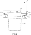
- a stator section 200 of the example gas turbine engine 100 includes a stator vane 212 having a vane foot 214 that is received within slot 204 defined within a case 202.
- the case 202 provides the support for the stator vane 212 within corresponding slot 204.
- the vane foot 214 is received within the slot 204 of the case 202.
- the slot 204 includes an outside facing side of surface 208 with a groove 206. To allow slot 204 to secure the vane foot 214, slot 204 further includes a narrow portion on a side that is open in the direction of stator vane 212.
- a wear liner 210 is disposed between the vane foot 214 and the inner surfaces of the slot 204.
- the wear liner 210 is axially installed and provides wear protection for the inner diameter (ID) of the fan case. More particularly, the wear liner 210 provides wear protection to slot 204 along with the vane foot 214, to prevent fretting and/or galling.
- the wear liner 210 includes a first hook 216 that receives the vane foot 214.
- the first hook 216 is disposed about a foot end.
- the second hook 218 includes a curved surface 228 that terminates with a second engaging end 225 that extends into a narrow portion leading into slot 226, which is a transverse surface of the vane foot 214.
- the contact between a foot surface 224 of the vane foot 214 and the second hook 218 of the wear liner 210 provides a sealing contact between the wear liner 210 and the vane foot 214.
- material properties of the sheet utilized to form the disclosed wear liner 210 are compatible with the temperatures and pressures encountered during operation.
- the sheet may comprise any material having attributes that may be desired and/or critical for the specific wear liner implementation.
- the sheet may comprise any suitable metal, ceramic, mineral, or plastic.
- the surface finish of the wear liner 210 is such that the desired contact seal is formed with the inside-facing side of surface 208 of the slot 204 and the surface of the vane foot 214.
- the wear liner 210 may include a coating to further inhibit wear and provide the desired sealing properties. Coatings typically used in the aerospace industry are known among those of ordinary skill in the art. Coatings that might be well-suited for various applications may include thermal spray coatings, ceramic coatings, cermet coatings, abradable coatings, etc.
- the wear liner 210 for a vane foot includes a first hook 216 and a second hook 218 connected by a base 227 to form a generally S-shaped channel.
- the wear liner 210 has an outer surface 229 adapted to lie against a first component, which includes a vane foot that is positioned in a slot.
- An inner surface 223 is adapted to lie against a second component, such as a surface of the case 202 defining a slot that is configured to secure a vane foot.
- a first engaging end 215 of the first hook 216 is adapted to engage the first component and a second engaging end 225 of the second hook 218 is adapted to engage the second component.
- the wear liner 500 includes an integral single sheet 502 construction.
- the integral single sheet 502 construction provides a continuous length of the wear liner 500 that may be cut in accordance with its intended installation. Constructing a single piece of material having bends 504, 506 as disclosed herein, eliminates or minimizes joints that may be formed by welding or through use of adhesives to secure the wear liner 500.
- the wear liner 500 is constructed through a progressive fabrication process that use press brakes to coin or air-bend stripped material into the shapes described herein, relative to various embodiments.
- a stripped material is formed in accordance with the precise bends, angles, and dimensions of a specific gas turbine engine.
- the shape of the disclosed wear liner 500 is formed by way of a series of in-line rollers that progressively bend the stripped material as it is moved through a series of inline rollers.
- the rollers cause the stripped material to coil to a precise curvature, which simplifies installation and ensures a proper seal between the finished wear liner and a vane foot.
- the wear liner 500 is cut from a coil according to the precise application properties.
- a continuous coil may be cut to lengths forming a 180° coil (e.g., half of the radius of a fan) or a full 360° coil.
- a manufacturing process may produce a wear liner 500 coil having any finished size, radius, or length.
- the disclosed wear liner 500 may be produced in six (6) 60° segments for portability, wherein the segments are attached end-to-end prior to installation.
- multiple segments that together comprise a full 360° wear liner 500 may each be installed individually.
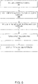
- FIG. 6 is a process flow showing steps for manufacturing a wear liner in accordance with various examples falling outside the scope of the claims.
- a manufacturing process may include rolling a stripped material (step 600) to form a first hook and a second hook connected by a base to form a generally S-shaped channel. Stripped material is rolled to form an outer surface (step 605) to lie against a first component (i.e., vane foot) the outer surface including a first engaging end. Stripped material is further rolled to form an inner surface (step 610) to lie against a second component.
- Manufacturing may further include forming a first engaging end (step 615) of the first hook to seal to the first component vane foot.
- a second engaging end is formed (step 620) of the second hook to seal to the slot.
- FIG. 7 is a process flow showing steps for installing a wear liner in accordance with various embodiments.
- Installing the wear liner may include inserting the wear liner into an inner diameter of a fan case (step 700), the wear liner comprising a first hook and a second hook connected by a base to provide a generally S-shaped channel (step 705), the wear liner having an outer surface pressed against a first component (i.e., vane foot) (step 710) and an inner surface pressed against a second component (step 715), a first engaging end of the first hook engaging the first component (i.e., vane foot) (step 720) and a second engaging end of the second hook engaging the second component (step 725).
Landscapes
- Engineering & Computer Science (AREA)
- Mechanical Engineering (AREA)
- General Engineering & Computer Science (AREA)
- Structures Of Non-Positive Displacement Pumps (AREA)
- Rotary Pumps (AREA)
- Turbine Rotor Nozzle Sealing (AREA)
Claims (8)
- Statorabschnitt (200) für ein Gasturbinentriebwerk (100), umfassend:ein Gehäuse (202), das einen Schlitz (204) beinhaltet;eine Statorschaufel (212), die einen Schaufelfuß (214) beinhaltet, der innerhalb des Schlitzes (204) aufgenommen ist;eine Verschleißauskleidung (210) für den Schaufelfuß (214), wobei die Verschleißauskleidung (210) Folgendes umfasst:
einen ersten Haken (216) und einen zweiten Haken (218), die durch eine Basis (227) verbunden sind, um einen S-förmigen Kanal bereitzustellen, wobei die Verschleißauskleidung (210) eine Außenfläche (229), die ausgelegt ist, um gegen eine erste Komponente (214) anzuliegen, und eine Innenfläche (223), die ausgelegt ist, um gegen eine zweite Komponente anzuliegen, aufweist, ein erstes Eingriffsende (215) des ersten Hakens (216), das dazu konfiguriert ist, gegen die erste Komponente zu drücken und an dieser abzudichten, und ein zweites Eingriffsende (225) des zweiten Hakens (218), das dazu konfiguriert ist, gegen die zweite Komponente zu drücken und an dieser abzudichten, wobei die erste Komponente der Schaufelfuß (214) ist, wobei der Schaufelfuß (214) ein vorderes Ende, ein hinteres Ende und eine Aussparung an einer axial verlaufenden Fläche benachbart zu mindestens einem von dem radial verlaufenden vorderen Ende oder dem radial verlaufenden hinteren Ende aufweist; dadurch gekennzeichnet, dass:das erste Eingriffsende (215) eine Kurve umfasst und sich in die Aussparung erstreckt;der erste Haken (216) an der Aussparung endet; undder erste Haken (216) dazu konfiguriert ist, den Schaufelfuß (214) aufzunehmen. - Statorabschnitt nach Anspruch 1, wobei das zweite Eingriffsende (225) eine Kurve umfasst, die sich in einen Bereich erstreckt, der in einen zweiten Schlitz (226) führt.
- Statorabschnitt nach Anspruch 1 oder 2, wobei die Verschleißauskleidung (210) eine einzelne Materialbahn umfasst.
- Verfahren zum Einsetzen einer Verschleißauskleidung in ein Gasturbinentriebwerk, umfassend:
Einlegen der Verschleißauskleidung (210) in einen Innendurchmesser eines Fangehäuses, wobei die Verschleißauskleidung (210) einen ersten Haken (216) und einen zweiten Haken (218) umfasst, die durch eine Basis (227) verbunden sind, um einen S-förmigen Kanal bereitzustellen, wobei die Verschleißauskleidung (210) eine Außenfläche (229), die gegen eine erste Komponente anliegt, und eine Innenfläche (223), die gegen eine zweite Komponente anliegt, aufweist, wobei ein erstes Eingriffsende (215) des ersten Hakens (216) in die erste Komponente (214) eingreift und ein zweites Eingriffsende (225) des zweiten Hakens (218) in die zweite Komponente (226) eingreift, wobei die erste Komponente ein Schaufelfuß (214) ist und das erste Eingriffsende (215) ausgebildet ist, um eine Kurve zu beinhalten und sich in eine Aussparung an einer axial verlaufenden Fläche benachbart zu mindestens einem von einem radial verlaufenden vorderen Ende oder einem radial verlaufenden hinteren Ende eines Schaufelfuße (214) zu erstrecken, wobei der erste Haken (216) den Schaufelfuß (214) aufnimmt und an der Aussparung endet. - Verfahren nach Anspruch 4, wobei die Verschleißauskleidung als eine 360°-Spule eingelegt wird.
- Verfahren nach Anspruch 4 oder 5, wobei die Verschleißauskleidung (210) einen ersten 180°-Abschnitt und einen zweiten 180°-Abschnitt umfasst, die Ende an Ende eingelegt sind, um eine 360°-Spule zu bilden.
- Verfahren nach einem der Ansprüche 4 bis 6, wobei das zweite Eingriffsende (225) ausgebildet ist, um eine Kurve zu beinhalten, die sich in einen Bereich eines zweiten Schlitzes (226) erstreckt.
- Verfahren nach einem der Ansprüche 4 bis 7, wobei die Verschleißauskleidung (210) aus einer einzelnen Materialbahn ausgebildet ist.
Applications Claiming Priority (1)
| Application Number | Priority Date | Filing Date | Title |
|---|---|---|---|
| US15/135,214 US11066951B2 (en) | 2016-04-21 | 2016-04-21 | Wear liner for fixed stator vanes |
Publications (3)
| Publication Number | Publication Date |
|---|---|
| EP3244017A2 EP3244017A2 (de) | 2017-11-15 |
| EP3244017A3 EP3244017A3 (de) | 2018-01-10 |
| EP3244017B1 true EP3244017B1 (de) | 2022-03-30 |
Family
ID=58158846
Family Applications (1)
| Application Number | Title | Priority Date | Filing Date |
|---|---|---|---|
| EP17157173.0A Active EP3244017B1 (de) | 2016-04-21 | 2017-02-21 | Statorabschnitt für ein gasturbinentriebwerk und zugehöriges verfahren zum einsetzen einer verschleissauskleidung innerhalb eines gasturbinentriebwerks |
Country Status (2)
| Country | Link |
|---|---|
| US (1) | US11066951B2 (de) |
| EP (1) | EP3244017B1 (de) |
Families Citing this family (4)
| Publication number | Priority date | Publication date | Assignee | Title |
|---|---|---|---|---|
| US11084150B2 (en) * | 2018-01-31 | 2021-08-10 | Raytheon Technologies Corporation | Wear liner installation tool |
| DE102020200073A1 (de) | 2020-01-07 | 2021-07-08 | Siemens Aktiengesellschaft | Leitschaufelkranz |
| FR3127982B1 (fr) * | 2021-10-13 | 2025-01-17 | Safran Aircraft Engines | Ensemble d’anneau mobile pour rotor de turbomachine |
| DE102024104404A1 (de) * | 2024-02-16 | 2025-08-21 | MTU Aero Engines AG | Leitschaufelsegment |
Citations (1)
| Publication number | Priority date | Publication date | Assignee | Title |
|---|---|---|---|---|
| US5749218A (en) * | 1993-12-17 | 1998-05-12 | General Electric Co. | Wear reduction kit for gas turbine combustors |
Family Cites Families (7)
| Publication number | Priority date | Publication date | Assignee | Title |
|---|---|---|---|---|
| US7784264B2 (en) | 2006-08-03 | 2010-08-31 | Siemens Energy, Inc. | Slidable spring-loaded transition-to-turbine seal apparatus and heat-shielding system, comprising the seal, at transition/turbine junction of a gas turbine engine |
| DE102007059220A1 (de) | 2007-12-07 | 2009-06-10 | Rolls-Royce Deutschland Ltd & Co Kg | Leitschaufelkranz für thermische Strömungsmaschinen, insbesondere Flugtriebwerke |
| FR2938872B1 (fr) | 2008-11-26 | 2015-11-27 | Snecma | Dispositif anti-usure pour aubes d'un distributeur de turbine d'une turbomachine aeronautique |
| GB2475704A (en) * | 2009-11-26 | 2011-06-01 | Alstom Technology Ltd | Diverting solid particles in an axial flow steam turbine |
| GB2477825B (en) | 2010-09-23 | 2015-04-01 | Rolls Royce Plc | Anti fret liner assembly |
| US8899914B2 (en) | 2012-01-05 | 2014-12-02 | United Technologies Corporation | Stator vane integrated attachment liner and spring damper |
| US9353649B2 (en) | 2013-01-08 | 2016-05-31 | United Technologies Corporation | Wear liner spring seal |
-
2016
- 2016-04-21 US US15/135,214 patent/US11066951B2/en active Active
-
2017
- 2017-02-21 EP EP17157173.0A patent/EP3244017B1/de active Active
Patent Citations (1)
| Publication number | Priority date | Publication date | Assignee | Title |
|---|---|---|---|---|
| US5749218A (en) * | 1993-12-17 | 1998-05-12 | General Electric Co. | Wear reduction kit for gas turbine combustors |
Non-Patent Citations (2)
| Title |
|---|
| ANONYMOUS: "intersect | Definition of intersect in English by Oxford Dictionaries", 20 February 2019 (2019-02-20), XP055559500, Retrieved from the Internet <URL:https://en.oxforddictionaries.com/definition/intersect> [retrieved on 20190220] * |
| ANONYMOUS: "Intersecting | Definition of Intersecting by Merriam-Webster", 20 February 2019 (2019-02-20), XP055559496, Retrieved from the Internet <URL:https://www.merriam-webster.com/dictionary/intersecting> [retrieved on 20190220] * |
Also Published As
| Publication number | Publication date |
|---|---|
| US20170306791A1 (en) | 2017-10-26 |
| EP3244017A2 (de) | 2017-11-15 |
| US11066951B2 (en) | 2021-07-20 |
| EP3244017A3 (de) | 2018-01-10 |
Similar Documents
| Publication | Publication Date | Title |
|---|---|---|
| EP2943659B1 (de) | Federdichtung mit verschleissschutzverkleidung | |
| EP3025030B1 (de) | Rinnendichtung für gasturbinenmotor | |
| EP3348803B1 (de) | Motormittelturbinenrahmen-transferröhre zur kühlung eines niederdruckturbinengehäuses | |
| EP2937513A2 (de) | Herstellungsverfahren für ein Bauteil und zugehöriges bauteil | |
| EP3004568B1 (de) | Gasturbinentriebwerk mit schwalbenschwanz-tobi-statorschaufel | |
| EP2984291B1 (de) | Leitschaufelsegment für einen gasturbinenmotor | |
| EP3034791A1 (de) | Wärmeübertragungssockel mit strömungsführungsmerkmalen | |
| EP2880282B1 (de) | Verdichterbaugruppe mit statorverdrehsicherungsnocken | |
| US11066951B2 (en) | Wear liner for fixed stator vanes | |
| EP3054094A1 (de) | Gasturbinenmotorturbinenschaufelablenkplatte und schlangenförmiger kühlkanal | |
| EP2938830A1 (de) | Schlangenförmiger kühlkanal mit winkelleisten für einen gasturbinenmotor | |
| EP2971585B1 (de) | Schienendichtung für eine gasturbinenschaufel | |
| EP3190266A1 (de) | Rotornabendichtung | |
| WO2014092834A2 (en) | High pressure rotor disk | |
| EP3036420B1 (de) | Achslagerstift mit lastausgleich | |
| EP2917508A1 (de) | Zapfluftschlitz | |
| EP2993303B1 (de) | Gasturbinenkomponente mit filmkühlloch mit tasche | |
| US20160377288A1 (en) | Rounded edges for gas path components | |
| EP3722569A1 (de) | Äussere laufschaufelluftdichtung und turbinenabschnitt | |
| EP3045666A1 (de) | Tragflächenplattform mit kühlungseinspeisungsöffnungen | |
| EP2961940B1 (de) | Konturierte äussere laufschaufelluftdichtung für einen gasturbinenmotor | |
| EP2938872B1 (de) | Schaufelunterfussabstandshalter mit hakenentfernung | |
| EP3467260A1 (de) | Gasturbinentriebwerksschaufel mit gekrümmter schaufelspitze | |
| EP4379192A1 (de) | Dichtungsnut mit beschichtung | |
| EP2961930B1 (de) | Kantenbehandlung für eine äussere laufschaufelluftdichtung |
Legal Events
| Date | Code | Title | Description |
|---|---|---|---|
| PUAI | Public reference made under article 153(3) epc to a published international application that has entered the european phase |
Free format text: ORIGINAL CODE: 0009012 |
|
| STAA | Information on the status of an ep patent application or granted ep patent |
Free format text: STATUS: THE APPLICATION HAS BEEN PUBLISHED |
|
| AK | Designated contracting states |
Kind code of ref document: A2 Designated state(s): AL AT BE BG CH CY CZ DE DK EE ES FI FR GB GR HR HU IE IS IT LI LT LU LV MC MK MT NL NO PL PT RO RS SE SI SK SM TR |
|
| AX | Request for extension of the european patent |
Extension state: BA ME |
|
| PUAL | Search report despatched |
Free format text: ORIGINAL CODE: 0009013 |
|
| AK | Designated contracting states |
Kind code of ref document: A3 Designated state(s): AL AT BE BG CH CY CZ DE DK EE ES FI FR GB GR HR HU IE IS IT LI LT LU LV MC MK MT NL NO PL PT RO RS SE SI SK SM TR |
|
| AX | Request for extension of the european patent |
Extension state: BA ME |
|
| RIC1 | Information provided on ipc code assigned before grant |
Ipc: F01D 9/04 20060101AFI20171207BHEP Ipc: F01D 25/24 20060101ALI20171207BHEP |
|
| STAA | Information on the status of an ep patent application or granted ep patent |
Free format text: STATUS: REQUEST FOR EXAMINATION WAS MADE |
|
| 17P | Request for examination filed |
Effective date: 20180710 |
|
| RBV | Designated contracting states (corrected) |
Designated state(s): AL AT BE BG CH CY CZ DE DK EE ES FI FR GB GR HR HU IE IS IT LI LT LU LV MC MK MT NL NO PL PT RO RS SE SI SK SM TR |
|
| STAA | Information on the status of an ep patent application or granted ep patent |
Free format text: STATUS: EXAMINATION IS IN PROGRESS |
|
| 17Q | First examination report despatched |
Effective date: 20190226 |
|
| RAP1 | Party data changed (applicant data changed or rights of an application transferred) |
Owner name: RAYTHEON TECHNOLOGIES CORPORATION |
|
| GRAP | Despatch of communication of intention to grant a patent |
Free format text: ORIGINAL CODE: EPIDOSNIGR1 |
|
| STAA | Information on the status of an ep patent application or granted ep patent |
Free format text: STATUS: GRANT OF PATENT IS INTENDED |
|
| GRAJ | Information related to disapproval of communication of intention to grant by the applicant or resumption of examination proceedings by the epo deleted |
Free format text: ORIGINAL CODE: EPIDOSDIGR1 |
|
| STAA | Information on the status of an ep patent application or granted ep patent |
Free format text: STATUS: EXAMINATION IS IN PROGRESS |
|
| INTG | Intention to grant announced |
Effective date: 20210806 |
|
| INTC | Intention to grant announced (deleted) | ||
| GRAP | Despatch of communication of intention to grant a patent |
Free format text: ORIGINAL CODE: EPIDOSNIGR1 |
|
| STAA | Information on the status of an ep patent application or granted ep patent |
Free format text: STATUS: GRANT OF PATENT IS INTENDED |
|
| INTG | Intention to grant announced |
Effective date: 20210929 |
|
| GRAS | Grant fee paid |
Free format text: ORIGINAL CODE: EPIDOSNIGR3 |
|
| GRAA | (expected) grant |
Free format text: ORIGINAL CODE: 0009210 |
|
| STAA | Information on the status of an ep patent application or granted ep patent |
Free format text: STATUS: THE PATENT HAS BEEN GRANTED |
|
| AK | Designated contracting states |
Kind code of ref document: B1 Designated state(s): AL AT BE BG CH CY CZ DE DK EE ES FI FR GB GR HR HU IE IS IT LI LT LU LV MC MK MT NL NO PL PT RO RS SE SI SK SM TR |
|
| REG | Reference to a national code |
Ref country code: GB Ref legal event code: FG4D |
|
| REG | Reference to a national code |
Ref country code: CH Ref legal event code: EP |
|
| REG | Reference to a national code |
Ref country code: DE Ref legal event code: R096 Ref document number: 602017055114 Country of ref document: DE |
|
| REG | Reference to a national code |
Ref country code: AT Ref legal event code: REF Ref document number: 1479368 Country of ref document: AT Kind code of ref document: T Effective date: 20220415 |
|
| REG | Reference to a national code |
Ref country code: IE Ref legal event code: FG4D |
|
| REG | Reference to a national code |
Ref country code: LT Ref legal event code: MG9D |
|
| PG25 | Lapsed in a contracting state [announced via postgrant information from national office to epo] |
Ref country code: SE Free format text: LAPSE BECAUSE OF FAILURE TO SUBMIT A TRANSLATION OF THE DESCRIPTION OR TO PAY THE FEE WITHIN THE PRESCRIBED TIME-LIMIT Effective date: 20220330 Ref country code: RS Free format text: LAPSE BECAUSE OF FAILURE TO SUBMIT A TRANSLATION OF THE DESCRIPTION OR TO PAY THE FEE WITHIN THE PRESCRIBED TIME-LIMIT Effective date: 20220330 Ref country code: NO Free format text: LAPSE BECAUSE OF FAILURE TO SUBMIT A TRANSLATION OF THE DESCRIPTION OR TO PAY THE FEE WITHIN THE PRESCRIBED TIME-LIMIT Effective date: 20220630 Ref country code: LT Free format text: LAPSE BECAUSE OF FAILURE TO SUBMIT A TRANSLATION OF THE DESCRIPTION OR TO PAY THE FEE WITHIN THE PRESCRIBED TIME-LIMIT Effective date: 20220330 Ref country code: HR Free format text: LAPSE BECAUSE OF FAILURE TO SUBMIT A TRANSLATION OF THE DESCRIPTION OR TO PAY THE FEE WITHIN THE PRESCRIBED TIME-LIMIT Effective date: 20220330 Ref country code: BG Free format text: LAPSE BECAUSE OF FAILURE TO SUBMIT A TRANSLATION OF THE DESCRIPTION OR TO PAY THE FEE WITHIN THE PRESCRIBED TIME-LIMIT Effective date: 20220630 |
|
| REG | Reference to a national code |
Ref country code: NL Ref legal event code: MP Effective date: 20220330 |
|
| REG | Reference to a national code |
Ref country code: AT Ref legal event code: MK05 Ref document number: 1479368 Country of ref document: AT Kind code of ref document: T Effective date: 20220330 |
|
| PG25 | Lapsed in a contracting state [announced via postgrant information from national office to epo] |
Ref country code: LV Free format text: LAPSE BECAUSE OF FAILURE TO SUBMIT A TRANSLATION OF THE DESCRIPTION OR TO PAY THE FEE WITHIN THE PRESCRIBED TIME-LIMIT Effective date: 20220330 Ref country code: GR Free format text: LAPSE BECAUSE OF FAILURE TO SUBMIT A TRANSLATION OF THE DESCRIPTION OR TO PAY THE FEE WITHIN THE PRESCRIBED TIME-LIMIT Effective date: 20220701 Ref country code: FI Free format text: LAPSE BECAUSE OF FAILURE TO SUBMIT A TRANSLATION OF THE DESCRIPTION OR TO PAY THE FEE WITHIN THE PRESCRIBED TIME-LIMIT Effective date: 20220330 |
|
| PG25 | Lapsed in a contracting state [announced via postgrant information from national office to epo] |
Ref country code: NL Free format text: LAPSE BECAUSE OF FAILURE TO SUBMIT A TRANSLATION OF THE DESCRIPTION OR TO PAY THE FEE WITHIN THE PRESCRIBED TIME-LIMIT Effective date: 20220330 |
|
| PG25 | Lapsed in a contracting state [announced via postgrant information from national office to epo] |
Ref country code: SM Free format text: LAPSE BECAUSE OF FAILURE TO SUBMIT A TRANSLATION OF THE DESCRIPTION OR TO PAY THE FEE WITHIN THE PRESCRIBED TIME-LIMIT Effective date: 20220330 Ref country code: SK Free format text: LAPSE BECAUSE OF FAILURE TO SUBMIT A TRANSLATION OF THE DESCRIPTION OR TO PAY THE FEE WITHIN THE PRESCRIBED TIME-LIMIT Effective date: 20220330 Ref country code: RO Free format text: LAPSE BECAUSE OF FAILURE TO SUBMIT A TRANSLATION OF THE DESCRIPTION OR TO PAY THE FEE WITHIN THE PRESCRIBED TIME-LIMIT Effective date: 20220330 Ref country code: PT Free format text: LAPSE BECAUSE OF FAILURE TO SUBMIT A TRANSLATION OF THE DESCRIPTION OR TO PAY THE FEE WITHIN THE PRESCRIBED TIME-LIMIT Effective date: 20220801 Ref country code: ES Free format text: LAPSE BECAUSE OF FAILURE TO SUBMIT A TRANSLATION OF THE DESCRIPTION OR TO PAY THE FEE WITHIN THE PRESCRIBED TIME-LIMIT Effective date: 20220330 Ref country code: EE Free format text: LAPSE BECAUSE OF FAILURE TO SUBMIT A TRANSLATION OF THE DESCRIPTION OR TO PAY THE FEE WITHIN THE PRESCRIBED TIME-LIMIT Effective date: 20220330 Ref country code: CZ Free format text: LAPSE BECAUSE OF FAILURE TO SUBMIT A TRANSLATION OF THE DESCRIPTION OR TO PAY THE FEE WITHIN THE PRESCRIBED TIME-LIMIT Effective date: 20220330 Ref country code: AT Free format text: LAPSE BECAUSE OF FAILURE TO SUBMIT A TRANSLATION OF THE DESCRIPTION OR TO PAY THE FEE WITHIN THE PRESCRIBED TIME-LIMIT Effective date: 20220330 |
|
| PG25 | Lapsed in a contracting state [announced via postgrant information from national office to epo] |
Ref country code: PL Free format text: LAPSE BECAUSE OF FAILURE TO SUBMIT A TRANSLATION OF THE DESCRIPTION OR TO PAY THE FEE WITHIN THE PRESCRIBED TIME-LIMIT Effective date: 20220330 Ref country code: IS Free format text: LAPSE BECAUSE OF FAILURE TO SUBMIT A TRANSLATION OF THE DESCRIPTION OR TO PAY THE FEE WITHIN THE PRESCRIBED TIME-LIMIT Effective date: 20220730 Ref country code: AL Free format text: LAPSE BECAUSE OF FAILURE TO SUBMIT A TRANSLATION OF THE DESCRIPTION OR TO PAY THE FEE WITHIN THE PRESCRIBED TIME-LIMIT Effective date: 20220330 |
|
| REG | Reference to a national code |
Ref country code: DE Ref legal event code: R097 Ref document number: 602017055114 Country of ref document: DE |
|
| PG25 | Lapsed in a contracting state [announced via postgrant information from national office to epo] |
Ref country code: DK Free format text: LAPSE BECAUSE OF FAILURE TO SUBMIT A TRANSLATION OF THE DESCRIPTION OR TO PAY THE FEE WITHIN THE PRESCRIBED TIME-LIMIT Effective date: 20220330 |
|
| PLBE | No opposition filed within time limit |
Free format text: ORIGINAL CODE: 0009261 |
|
| STAA | Information on the status of an ep patent application or granted ep patent |
Free format text: STATUS: NO OPPOSITION FILED WITHIN TIME LIMIT |
|
| 26N | No opposition filed |
Effective date: 20230103 |
|
| PG25 | Lapsed in a contracting state [announced via postgrant information from national office to epo] |
Ref country code: SI Free format text: LAPSE BECAUSE OF FAILURE TO SUBMIT A TRANSLATION OF THE DESCRIPTION OR TO PAY THE FEE WITHIN THE PRESCRIBED TIME-LIMIT Effective date: 20220330 |
|
| P01 | Opt-out of the competence of the unified patent court (upc) registered |
Effective date: 20230520 |
|
| PG25 | Lapsed in a contracting state [announced via postgrant information from national office to epo] |
Ref country code: IT Free format text: LAPSE BECAUSE OF FAILURE TO SUBMIT A TRANSLATION OF THE DESCRIPTION OR TO PAY THE FEE WITHIN THE PRESCRIBED TIME-LIMIT Effective date: 20220330 |
|
| PG25 | Lapsed in a contracting state [announced via postgrant information from national office to epo] |
Ref country code: MC Free format text: LAPSE BECAUSE OF FAILURE TO SUBMIT A TRANSLATION OF THE DESCRIPTION OR TO PAY THE FEE WITHIN THE PRESCRIBED TIME-LIMIT Effective date: 20220330 |
|
| REG | Reference to a national code |
Ref country code: CH Ref legal event code: PL |
|
| REG | Reference to a national code |
Ref country code: BE Ref legal event code: MM Effective date: 20230228 |
|
| PG25 | Lapsed in a contracting state [announced via postgrant information from national office to epo] |
Ref country code: LU Free format text: LAPSE BECAUSE OF NON-PAYMENT OF DUE FEES Effective date: 20230221 Ref country code: LI Free format text: LAPSE BECAUSE OF NON-PAYMENT OF DUE FEES Effective date: 20230228 Ref country code: CH Free format text: LAPSE BECAUSE OF NON-PAYMENT OF DUE FEES Effective date: 20230228 |
|
| REG | Reference to a national code |
Ref country code: IE Ref legal event code: MM4A |
|
| PG25 | Lapsed in a contracting state [announced via postgrant information from national office to epo] |
Ref country code: IE Free format text: LAPSE BECAUSE OF NON-PAYMENT OF DUE FEES Effective date: 20230221 |
|
| PG25 | Lapsed in a contracting state [announced via postgrant information from national office to epo] |
Ref country code: BE Free format text: LAPSE BECAUSE OF NON-PAYMENT OF DUE FEES Effective date: 20230228 |
|
| PG25 | Lapsed in a contracting state [announced via postgrant information from national office to epo] |
Ref country code: CY Free format text: LAPSE BECAUSE OF FAILURE TO SUBMIT A TRANSLATION OF THE DESCRIPTION OR TO PAY THE FEE WITHIN THE PRESCRIBED TIME-LIMIT; INVALID AB INITIO Effective date: 20170221 |
|
| PG25 | Lapsed in a contracting state [announced via postgrant information from national office to epo] |
Ref country code: HU Free format text: LAPSE BECAUSE OF FAILURE TO SUBMIT A TRANSLATION OF THE DESCRIPTION OR TO PAY THE FEE WITHIN THE PRESCRIBED TIME-LIMIT; INVALID AB INITIO Effective date: 20170221 |
|
| REG | Reference to a national code |
Ref country code: DE Ref legal event code: R081 Ref document number: 602017055114 Country of ref document: DE Owner name: RTX CORPORATION (N.D.GES.D. STAATES DELAWARE),, US Free format text: FORMER OWNER: RAYTHEON TECHNOLOGIES CORPORATION, FARMINGTON, CT, US |
|
| PG25 | Lapsed in a contracting state [announced via postgrant information from national office to epo] |
Ref country code: TR Free format text: LAPSE BECAUSE OF FAILURE TO SUBMIT A TRANSLATION OF THE DESCRIPTION OR TO PAY THE FEE WITHIN THE PRESCRIBED TIME-LIMIT Effective date: 20220330 |
|
| PGFP | Annual fee paid to national office [announced via postgrant information from national office to epo] |
Ref country code: GB Payment date: 20260122 Year of fee payment: 10 |
|
| PGFP | Annual fee paid to national office [announced via postgrant information from national office to epo] |
Ref country code: DE Payment date: 20260121 Year of fee payment: 10 |
|
| PGFP | Annual fee paid to national office [announced via postgrant information from national office to epo] |
Ref country code: FR Payment date: 20260121 Year of fee payment: 10 |