EP3244021B1 - Maschine umfassend eine dichtung - Google Patents
Maschine umfassend eine dichtung Download PDFInfo
- Publication number
- EP3244021B1 EP3244021B1 EP17167077.1A EP17167077A EP3244021B1 EP 3244021 B1 EP3244021 B1 EP 3244021B1 EP 17167077 A EP17167077 A EP 17167077A EP 3244021 B1 EP3244021 B1 EP 3244021B1
- Authority
- EP
- European Patent Office
- Prior art keywords
- leg
- length
- engine
- seal
- component
- Prior art date
- Legal status (The legal status is an assumption and is not a legal conclusion. Google has not performed a legal analysis and makes no representation as to the accuracy of the status listed.)
- Active
Links
Images



Classifications
-
- F—MECHANICAL ENGINEERING; LIGHTING; HEATING; WEAPONS; BLASTING
- F01—MACHINES OR ENGINES IN GENERAL; ENGINE PLANTS IN GENERAL; STEAM ENGINES
- F01D—NON-POSITIVE DISPLACEMENT MACHINES OR ENGINES, e.g. STEAM TURBINES
- F01D11/00—Preventing or minimising internal leakage of working-fluid, e.g. between stages
- F01D11/005—Sealing means between non relatively rotating elements
-
- F—MECHANICAL ENGINEERING; LIGHTING; HEATING; WEAPONS; BLASTING
- F01—MACHINES OR ENGINES IN GENERAL; ENGINE PLANTS IN GENERAL; STEAM ENGINES
- F01D—NON-POSITIVE DISPLACEMENT MACHINES OR ENGINES, e.g. STEAM TURBINES
- F01D25/00—Component parts, details, or accessories, not provided for in, or of interest apart from, other groups
- F01D25/24—Casings; Casing parts, e.g. diaphragms, casing fastenings
- F01D25/246—Fastening of diaphragms or stator-rings
-
- F—MECHANICAL ENGINEERING; LIGHTING; HEATING; WEAPONS; BLASTING
- F02—COMBUSTION ENGINES; HOT-GAS OR COMBUSTION-PRODUCT ENGINE PLANTS
- F02C—GAS-TURBINE PLANTS; AIR INTAKES FOR JET-PROPULSION PLANTS; CONTROLLING FUEL SUPPLY IN AIR-BREATHING JET-PROPULSION PLANTS
- F02C7/00—Features, components parts, details or accessories, not provided for in, or of interest apart form groups F02C1/00 - F02C6/00; Air intakes for jet-propulsion plants
- F02C7/20—Mounting or supporting of plant; Accommodating heat expansion or creep
-
- F—MECHANICAL ENGINEERING; LIGHTING; HEATING; WEAPONS; BLASTING
- F02—COMBUSTION ENGINES; HOT-GAS OR COMBUSTION-PRODUCT ENGINE PLANTS
- F02C—GAS-TURBINE PLANTS; AIR INTAKES FOR JET-PROPULSION PLANTS; CONTROLLING FUEL SUPPLY IN AIR-BREATHING JET-PROPULSION PLANTS
- F02C7/00—Features, components parts, details or accessories, not provided for in, or of interest apart form groups F02C1/00 - F02C6/00; Air intakes for jet-propulsion plants
- F02C7/28—Arrangement of seals
-
- F—MECHANICAL ENGINEERING; LIGHTING; HEATING; WEAPONS; BLASTING
- F16—ENGINEERING ELEMENTS AND UNITS; GENERAL MEASURES FOR PRODUCING AND MAINTAINING EFFECTIVE FUNCTIONING OF MACHINES OR INSTALLATIONS; THERMAL INSULATION IN GENERAL
- F16J—PISTONS; CYLINDERS; SEALINGS
- F16J15/00—Sealings
- F16J15/02—Sealings between relatively-stationary surfaces
- F16J15/021—Sealings between relatively-stationary surfaces with elastic packing
- F16J15/022—Sealings between relatively-stationary surfaces with elastic packing characterised by structure or material
-
- F—MECHANICAL ENGINEERING; LIGHTING; HEATING; WEAPONS; BLASTING
- F16—ENGINEERING ELEMENTS AND UNITS; GENERAL MEASURES FOR PRODUCING AND MAINTAINING EFFECTIVE FUNCTIONING OF MACHINES OR INSTALLATIONS; THERMAL INSULATION IN GENERAL
- F16J—PISTONS; CYLINDERS; SEALINGS
- F16J15/00—Sealings
- F16J15/02—Sealings between relatively-stationary surfaces
- F16J15/06—Sealings between relatively-stationary surfaces with solid packing compressed between sealing surfaces
- F16J15/08—Sealings between relatively-stationary surfaces with solid packing compressed between sealing surfaces with exclusively metal packing
- F16J15/0887—Sealings between relatively-stationary surfaces with solid packing compressed between sealing surfaces with exclusively metal packing the sealing effect being obtained by elastic deformation of the packing
-
- F—MECHANICAL ENGINEERING; LIGHTING; HEATING; WEAPONS; BLASTING
- F05—INDEXING SCHEMES RELATING TO ENGINES OR PUMPS IN VARIOUS SUBCLASSES OF CLASSES F01-F04
- F05D—INDEXING SCHEME FOR ASPECTS RELATING TO NON-POSITIVE-DISPLACEMENT MACHINES OR ENGINES, GAS-TURBINES OR JET-PROPULSION PLANTS
- F05D2220/00—Application
- F05D2220/30—Application in turbines
- F05D2220/32—Application in turbines in gas turbines
-
- F—MECHANICAL ENGINEERING; LIGHTING; HEATING; WEAPONS; BLASTING
- F05—INDEXING SCHEMES RELATING TO ENGINES OR PUMPS IN VARIOUS SUBCLASSES OF CLASSES F01-F04
- F05D—INDEXING SCHEME FOR ASPECTS RELATING TO NON-POSITIVE-DISPLACEMENT MACHINES OR ENGINES, GAS-TURBINES OR JET-PROPULSION PLANTS
- F05D2240/00—Components
- F05D2240/55—Seals
-
- F—MECHANICAL ENGINEERING; LIGHTING; HEATING; WEAPONS; BLASTING
- F05—INDEXING SCHEMES RELATING TO ENGINES OR PUMPS IN VARIOUS SUBCLASSES OF CLASSES F01-F04
- F05D—INDEXING SCHEME FOR ASPECTS RELATING TO NON-POSITIVE-DISPLACEMENT MACHINES OR ENGINES, GAS-TURBINES OR JET-PROPULSION PLANTS
- F05D2250/00—Geometry
- F05D2250/10—Two-dimensional
-
- F—MECHANICAL ENGINEERING; LIGHTING; HEATING; WEAPONS; BLASTING
- F05—INDEXING SCHEMES RELATING TO ENGINES OR PUMPS IN VARIOUS SUBCLASSES OF CLASSES F01-F04
- F05D—INDEXING SCHEME FOR ASPECTS RELATING TO NON-POSITIVE-DISPLACEMENT MACHINES OR ENGINES, GAS-TURBINES OR JET-PROPULSION PLANTS
- F05D2250/00—Geometry
- F05D2250/70—Shape
-
- F—MECHANICAL ENGINEERING; LIGHTING; HEATING; WEAPONS; BLASTING
- F05—INDEXING SCHEMES RELATING TO ENGINES OR PUMPS IN VARIOUS SUBCLASSES OF CLASSES F01-F04
- F05D—INDEXING SCHEME FOR ASPECTS RELATING TO NON-POSITIVE-DISPLACEMENT MACHINES OR ENGINES, GAS-TURBINES OR JET-PROPULSION PLANTS
- F05D2260/00—Function
- F05D2260/94—Functionality given by mechanical stress related aspects such as low cycle fatigue [LCF] of high cycle fatigue [HCF]
- F05D2260/941—Functionality given by mechanical stress related aspects such as low cycle fatigue [LCF] of high cycle fatigue [HCF] particularly aimed at mechanical or thermal stress reduction
Definitions
- the present invention relates to an engine comprising compressor, combustion, and turbine sections, wherein the engine also comprises a seal interfacing to a load.
- Gas turbine engines such as those which power aircraft and industrial equipment, employ a compressor to compress air that is drawn into the engine and a turbine to capture energy associated with the combustion of a fuel-air mixture.
- the fuel-air mixture may form part of a primary/core flow 202 and may be used to generate thrust.
- the products of combustion may be at elevated temperatures, which may cause the turbine components to see temperatures as hot as 2000 degrees Fahrenheit (approximately 1093 degrees Celsius).
- At least a portion of one or more secondary flows may provide cooling air to turbine components.
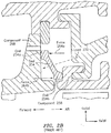
- the air 208 may be sourced from, e.g., the compressor. Since the amount of air 208 diverted to provide cooling impacts the performance/efficiency of an engine, seals (see FIG. 2B - seal 254) are incorporated as part of a secondary flow system to reduce (e.g., minimize) leakage.
- a conventional two-point axial ring seal 254 is shown.
- the seal 254 is commonly referred to as a dog-bone seal and operates as a mechanical, non-linear spring.
- An axial interference fit is provided between the seal 254 and adjacent components (e.g., component 258), which causes the seal to be subject to a rolling motion.
- the ends 254a and 254b of the seal 254 may be subject to a rolling motion, where the end 254a may be urged aft and the end 254b may be urged forward in FIG. 2B .
- hoop stress is introduced which acts in a restorative manner.
- elastic restorative forces imposed on the ends 254a and 254b are shown via arrows 264a and 264b, respectively.
- the seal 254 maintains contact with the adjacent components (e.g., the component 258, component 268) despite axial motion and a pressure differential that urges the seal 254 to lose contact with the components.
- a pressure load 270 may be imposed on the seal 254, where the load 270 is a result of the secondary flows 208 being at an elevated pressure.
- Creep occurs when the material of the seal 254 is subjected to elevated stress (e.g., elevated temperature) for extended periods of time. Creep causes the material of the seal 254 to permanently deform (based on the deflected state/position that the seal 254 assumes), even when the magnitude of the stress is below the material's yield strength. Creep degrades the seal 254's ability to withstand the load 270 over time, which can cause the seal 254 (e.g., the end 254b) to lose contact with an adjacent component (e.g., the component 258).
- elevated stress e.g., elevated temperature
- Creep causes the material of the seal 254 to permanently deform (based on the deflected state/position that the seal 254 assumes), even when the magnitude of the stress is below the material's yield strength. Creep degrades the seal 254's ability to withstand the load 270 over time, which can cause the seal 254 (e.g., the end 254b) to lose contact with
- WO 2014/150147 A1 discloses a prior art engine as set forth in the preamble of claim 1.
- the invention provides an engine as recited in claim 1.
- the first leg has a first length
- the second leg has a second length
- the third leg has a third length
- the third length is at least 10% of at least one of the first length or the second length.
- the seal further comprises a fourth leg that emanates from the center point.
- the fourth leg has a fourth length, and a summation of the third length and the fourth length is at least 10% of at least one of the first length or the second length.
- the third leg is separated from each of the first leg and the second leg by approximately 90 degrees.
- the fourth leg is separated from each of the first leg and the second leg by approximately 90 degrees.
- the seal includes a nickel alloy.
- the second component is configured to operate at a temperature that is within a range of 648 degrees Celsius to 1093 degrees Celsius.
- the second component includes a blade outer air seal support.
- the first component includes an outer case.
- the seal is configured to interface to a pressure load.
- the pressure load includes air sourced from the compressor section.
- the third length is less than 200% of each of the first length and the second length.
- the summation of the third length and the fourth length is less than 200% of each of the first length and the second length.
- connections are set forth between elements in the following description and in the drawings (the contents of which are included in this disclosure by way of reference). It is noted that these connections are general and, unless specified otherwise, may be direct or indirect and that this specification is not intended to be limiting in this respect.
- a coupling between two or more entities may refer to a direct connection or an indirect connection.
- An indirect connection may incorporate one or more intervening entities.
- apparatuses, systems, and methods are directed to a creep resistant axial ring seal.
- the seal may include three or more full-ring features that emanate from a center of cross-sectional rotation. Creep may occur at a first of the features (e.g., a contact interface between the seal and another component), whereas the other features may provide rolling resistance and resistance to load (e.g., pressure load).
- FIG. 1 is a side cutaway illustration of a geared turbine engine 10.
- This turbine engine 10 extends along an axial centerline 12 between an upstream airflow inlet 14 and a downstream airflow exhaust 16.
- the turbine engine 10 includes a fan section 18, a compressor section 19, a combustor section 20 and a turbine section 21.
- the compressor section 19 includes a low pressure compressor (LPC) section 19A and a high pressure compressor (HPC) section 19B.
- the turbine section 21 includes a high pressure turbine (HPT) section 21A and a low pressure turbine (LPT) section 21B.
- the engine sections 18-21 are arranged sequentially along the centerline 12 within an engine housing 22.
- Each of the engine sections 18-19B, 21A and 21B includes a respective rotor 24-28.
- Each of these rotors 24-28 includes a plurality of rotor blades arranged circumferentially around and connected to one or more respective rotor disks.
- the rotor blades may be formed integral with or mechanically fastened, welded, brazed, adhered and/or otherwise attached to the respective rotor disk(s).
- the fan rotor 24 is connected to a gear train 30, for example, through a fan shaft 32.
- the gear train 30 and the LPC rotor 25 are connected to and driven by the LPT rotor 28 through a low speed shaft 33.
- the HPC rotor 26 is connected to and driven by the HPT rotor 27 through a high speed shaft 34.
- the shafts 32-34 are rotatably supported by a plurality of bearings 36; e.g., rolling element and/or thrust bearings. Each of these bearings 36 is connected to the engine housing 22 by at least one stationary structure such as, for example, an annular support strut.
- the air within the core gas path 38 may be referred to as "core air”.
- the air within the bypass gas path 40 may be referred to as "bypass air”.
- the core air is directed through the engine sections 19-21, and exits the turbine engine 10 through the airflow exhaust 16 to provide forward engine thrust.
- fuel is injected into a combustion chamber 42 and mixed with compressed core air. This fuel-core air mixture is ignited to power the turbine engine 10.
- the bypass air is directed through the bypass gas path 40 and out of the turbine engine 10 through a bypass nozzle 44 to provide additional forward engine thrust. This additional forward engine thrust may account for a majority (e.g., more than 70 percent) of total engine thrust.
- at least some of the bypass air may be directed out of the turbine engine 10 through a thrust reverser to provide reverse engine thrust.
- FIG. 1 represents one possible configuration for an engine 10.
- the invention may be applied in connection with other environments, including additional configurations for gas turbine engines.
- the invention may be applied in connection with non-geared engines.
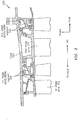
- a turbine section 300 of an engine is shown.
- the turbine section 300 may correspond to the high pressure turbine (HPT) section 21A of the engine 10 of FIG. 1 .
- HPT high pressure turbine
- the turbine section 300 is shown as including a first stage vane 302, a first stage blade outer air seal (BOAS)/BOAS support 308, a second stage vane 314, and a second stage BOAS/BOAS support 320.
- An outer case 326 may provide structural support for the vanes 302 and 314 and the BOAS/BOAS supports 308 and 320.
- a seal may be incorporated as part of one or more portions of the turbine section 300. For example, a seal may be incorporated as part of the BOAS/BOAS supports 308 and 320.
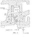
- FIG. 4 illustrates an example of a seal 454 that may be, according to the present invention, included as part of the turbine section 300 of FIG. 3 .
- the seal 454 may be a full-hoop/full-ring structure (see, e.g., FIG. 6A ), a cross-section of which is shown in FIGS. 4 and 6B .
- the seal 454 includes at least three legs, denoted in FIG. 4 via reference characters 466a, 466b, and 466c.
- the legs 466a-466c emanate from a center point 472 of the seal 454.
- the legs 466a, 466b, and 466c terminate at ends 454a, 454b, and 454c, respectively.
- the end 454a contacts (interfaces to) a component 468 and the end 454b contacts (interfaces to) a component 458.
- the component 458 may operate at elevated temperatures [in some embodiments, temperatures within a range of 648 degrees Celsius to 1093 degrees Celsius (1200 degrees Fahrenheit to 2000 degrees Fahrenheit)], such that the material of the seal 454 at the end 454b may creep. Conventionally, such creep might compromise the integrity/functionality of a seal in the manner described above because this "hot" portion of the seal is needed for stiffness to resist/counter a load (e.g., a pressure load 470). However, other features of the seal 454 provide stiffness against the load 470.
- the leg 466c may be cooler than the leg 466b because the leg 466c might not be in contact with the component 458. As such, the leg 466c provides stiffness to counter the load 470. Moreover, the sealing contacts are maintained at the end 454a with the component 468 and the end 454b with the component 458.
- the leg 466a may have a length equal to L a
- the leg 466b may have a length L b
- the leg 466c may have a length equal to L c , respectively.
- the lengths L a and L b may be approximately equal.
- the length L c may be equal to at least one of the lengths L a and L b .
- the hoop stresses may be equal in the legs 466a, 466b, and 466c (at least to a first order approximation).
- the length L c may be equal to at least a fraction/percentage of at least one of the lengths L a or L b .
- the length L c may be at least 10% of one of the lengths L a or L b .
- the length L c may be less than 200% of at least one of the lengths L a or L b .
- the leg 466c is shown as being oriented at approximately 90 degrees relative to each of the legs 466a and 466b.
- the legs 466a and 466b may emanate from the center point 472 in substantially opposite directions, thereby forming an approximate angle of 180 degrees between the legs 466a and 466b.
- the arrangement of the legs 466a-466c in terms of the angular separations of the legs 466a-466c is illustrative; other angular values or patterns for the seal 454 may be used.
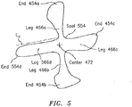
- FIG. 5 illustrates a seal 554 that may be used in some embodiments.
- the seal 554 is shown as including the legs 466a-466c emanating from the center point 472 similar to the seal 454.
- the seal 554 also may include another (e.g., fourth) leg 566d that emanates from the center point 472 and terminates at an end 554d.
- the leg 566d may have a length L d as measured between the center point 472 and the end 554d. Referring to FIGS. 4 and 5 , a summation of the lengths L c and L d may be equal to at least a fraction/percentage of at least one of the lengths L a or L b .
- the summation of the lengths L c and L d may be at least 10% of at least one of the lengths L a or L b .
- the summation of the lengths L c and L d may be less than 200% of at least one of the lengths L a or L b .
- each of the legs 466a-466c and the leg 566d are shown as being oriented at an angle that is approximately 90 degrees relative to the adjacent legs.
- the arrangement of the legs 466a-466c and 566d in terms of the angular separations of the legs 466a-466c and 566d is illustrative; other angular values or patterns for the seal 554 may be used.
- a seal (e.g., the seal 454 or the seal 554) may be manufactured of one or more materials.
- the seal may include nickel alloy, Inconel® 718 alloy, etc.
- a seal that has an enhanced lifetime relative to a conventional seal, where the useable lifetime of the seal is based on the seal's ability to withstand a load (e.g., pressure load). Creep may occur at an interface where the seal contacts a component that is operating at elevated temperatures. Other features/points of the seal may provide stiffness to the load while still enabling the seal to maintain contact with one or more adjacent components. Seals in accordance with this disclosure may consume substantially the same footprint as a conventional seal, thereby allowing for the replacement of conventional seals on legacy platforms without a need to redesign the layout of the legacy platforms. Seals in accordance with this disclosure may be incorporated in closer proximity to a primary/core flow path and/or the first stage of a turbine section relative to conventional seals due to the thermal characteristics associated with the seals of this disclosure.
- a load e.g., pressure load
Landscapes
- Engineering & Computer Science (AREA)
- General Engineering & Computer Science (AREA)
- Mechanical Engineering (AREA)
- Chemical & Material Sciences (AREA)
- Combustion & Propulsion (AREA)
- Gasket Seals (AREA)
- Turbine Rotor Nozzle Sealing (AREA)
Claims (15)
- Triebwerk (10), umfassend:einen Verdichterabschnitt (19);einen Brennkammerabschnitt (20) axial stromabwärts von dem Verdichterabschnitt (19);einen Turbinenabschnitt (21; 300) axial stromabwärts von dem Brennkammerabschnitt (20), wobei der Turbinenabschnitt (21; 300) eine erste Komponente (468) und eine zweite Komponente (458) beinhaltet; undeine Dichtung (454; 554), welche in den Turbinenabschnitt (21; 300) eingebaut ist, wobei die Dichtung (454; 554) Folgendes beinhaltet:einen ersten Schenkel (466a), welcher von einem Mittelpunkt (472) der Dichtung (454; 554) ausgeht, wobei der erste Schenkel (466a) ein erstes Ende (454a) beinhaltet, welches die erste Komponente (468) berührt;einen zweiten Schenkel (466b), welches von dem Mittelpunkt (472) ausgeht, wobei der zweite Schenkel (466b) ein zweites Ende (454b) beinhaltet, welches die zweite Komponente (458) berührt; undeinen dritten Schenkel (466c), welches von dem Mittelpunkt (472) ausgeht;wobei die Dichtung (454; 554) dazu konfiguriert ist, eine Schnittstelle mit einer Belastung (470) zu bilden;dadurch gekennzeichnet, dass:
der dritte Schenkel (466) Steifheit bereitstellt, um einem Biegen entgegenzuwirken, welches durch die Belastung (470) verursacht wird, so dass während des Betriebs des Triebwerks die Dichtungsberührungen an dem ersten Ende (454a) mit der ersten Komponente (468) und an dem zweiten Ende (454b) mit der zweiten Komponente (458) aufrechterhalten werden. - Triebwerk nach Anspruch 1, wobei der erste Schenkel (466a) eine erste Länge (La) aufweist, der zweite Schenkel (466b) eine zweite Länge (Lb) aufweist und der dritte Schenkel (466c) eine dritte Länge (Lc) aufweist.
- Triebwerk nach Anspruch 2, wobei die dritte Länge (Lc) mindestens 10 % von mindestens einer von der ersten Länge (La) oder der zweiten Länge (Lb) ist.
- Triebwerk nach Anspruch 3, wobei die dritte Länge (Lc) weniger als 200 % von jeder der ersten Länge (La) und der zweiten Länge (Lb) ist.
- Triebwerk nach einem der vorstehenden Ansprüche, ferner umfassend:
einen vierten Schenkel (566d), welches von dem Mittelpunkt (472) ausgeht. - Triebwerk nach Anspruch 5, wobei der vierte Schenkel (566d) eine vierte Länge (Ld) aufweist, und wobei eine Summe des dritten Schenkels (Lc) und des vierten Schenkels (Ld) mindestens 10 % von mindestens einer der ersten Länge (La) oder der zweiten Länge (Lb) ist.
- Triebwerk nach Anspruch 6, wobei die Summe der dritten Länge (Lc) und der vierten Länge (Ld) weniger als 200 % von jeder der ersten Länge (La) und der zweiten Länge (Lb) ist.
- Triebwerk nach einem der vorstehenden Ansprüche, wobei der dritte Schenkel (466c) von jedem des ersten Schenkels (466a) und des zweiten Schenkels (466b) durch ungefähr 90 Grad getrennt ist.
- Triebwerk nach Anspruch 8, wobei ein oder der vierte Schenkel (566d) von jedem des ersten Schenkels (466a) und des zweiten Schenkels (466b) durch ungefähr 90 Grad getrennt ist.
- Triebwerk nach einem der vorstehenden Ansprüche, wobei die Dichtung eine Nickellegierung beinhaltet.
- Triebwerk nach einem der vorstehenden Ansprüche, wobei die zweite Komponente (458) dazu konfiguriert ist, bei einer Temperatur betrieben zu werden, welche in einem Bereich von 648 Grad Celsius bis 1093 Grad Celsius liegt.
- Triebwerk nach einem der vorstehenden Ansprüche, wobei die zweite Komponente (458) einen Laufschaufelaußenluftdichtungsträger (320) beinhaltet, wobei optional die erste Komponente (468) ein äußeres Gehäuse (326) beinhaltet.
- Triebwerk nach einem der vorstehenden Ansprüche, wobei die Dichtung (454; 554) dazu konfiguriert ist, eine Schnittstelle mit einer Druckbelastung (470) zu bilden.
- Triebwerk nach Anspruch 13, wobei die Druckbelastung (470) Luft beinhaltet, welche aus dem Verdichterabschnitt (19) stammt.
- Triebwerk nach einem der vorstehenden Ansprüche, wobei der dritte Schenkel (466c) ein distales Ende (454c) beinhaltet, welches eine Komponente (468, 458) nicht berührt.
Applications Claiming Priority (1)
| Application Number | Priority Date | Filing Date | Title |
|---|---|---|---|
| US15/137,395 US10408074B2 (en) | 2016-04-25 | 2016-04-25 | Creep resistant axial ring seal |
Publications (2)
| Publication Number | Publication Date |
|---|---|
| EP3244021A1 EP3244021A1 (de) | 2017-11-15 |
| EP3244021B1 true EP3244021B1 (de) | 2021-07-14 |
Family
ID=58606059
Family Applications (1)
| Application Number | Title | Priority Date | Filing Date |
|---|---|---|---|
| EP17167077.1A Active EP3244021B1 (de) | 2016-04-25 | 2017-04-19 | Maschine umfassend eine dichtung |
Country Status (2)
| Country | Link |
|---|---|
| US (1) | US10408074B2 (de) |
| EP (1) | EP3244021B1 (de) |
Family Cites Families (34)
| Publication number | Priority date | Publication date | Assignee | Title |
|---|---|---|---|---|
| US3359687A (en) | 1964-08-17 | 1967-12-26 | Haveg Industries Inc | Expansible seal |
| US4314792A (en) | 1978-12-20 | 1982-02-09 | United Technologies Corporation | Turbine seal and vane damper |
| US5536022A (en) | 1990-08-24 | 1996-07-16 | United Technologies Corporation | Plasma sprayed abradable seals for gas turbine engines |
| US5304031A (en) | 1993-02-25 | 1994-04-19 | The United States Of America As Represented By The Secretary Of The Air Force | Outer air seal for a gas turbine engine |
| US5365901A (en) | 1993-11-15 | 1994-11-22 | Freudenberg-Nok General Partnership | Low creep flange and engine cover assembly |
| US5797723A (en) * | 1996-11-13 | 1998-08-25 | General Electric Company | Turbine flowpath seal |
| US6076835A (en) * | 1997-05-21 | 2000-06-20 | Allison Advanced Development Company | Interstage van seal apparatus |
| JP4031590B2 (ja) * | 1999-03-08 | 2008-01-09 | 三菱重工業株式会社 | 燃焼器の尾筒シール構造及びその構造を用いたガスタービン |
| US6241471B1 (en) | 1999-08-26 | 2001-06-05 | General Electric Co. | Turbine bucket tip shroud reinforcement |
| JP3840556B2 (ja) * | 2002-08-22 | 2006-11-01 | 川崎重工業株式会社 | 燃焼器ライナのシール構造 |
| GB2401658B (en) * | 2003-05-16 | 2006-07-26 | Rolls Royce Plc | Sealing arrangement |
| JP4322600B2 (ja) * | 2003-09-02 | 2009-09-02 | イーグル・エンジニアリング・エアロスペース株式会社 | シール装置 |
| JP4727934B2 (ja) * | 2004-02-20 | 2011-07-20 | イーグル・エンジニアリング・エアロスペース株式会社 | シール装置 |
| US7435049B2 (en) | 2004-03-30 | 2008-10-14 | General Electric Company | Sealing device and method for turbomachinery |
| US8695989B2 (en) * | 2004-04-30 | 2014-04-15 | Siemens Aktiengesellschaft | Hot gas seal |
| US7527469B2 (en) * | 2004-12-10 | 2009-05-05 | Siemens Energy, Inc. | Transition-to-turbine seal apparatus and kit for transition/turbine junction of a gas turbine engine |
| JP4476152B2 (ja) * | 2005-04-01 | 2010-06-09 | 三菱重工業株式会社 | ガスタービン燃焼器 |
| US7784264B2 (en) * | 2006-08-03 | 2010-08-31 | Siemens Energy, Inc. | Slidable spring-loaded transition-to-turbine seal apparatus and heat-shielding system, comprising the seal, at transition/turbine junction of a gas turbine engine |
| US20080124210A1 (en) | 2006-11-28 | 2008-05-29 | Peter Wayte | Rotary assembly components and methods of fabricating such components |
| US8157511B2 (en) * | 2008-09-30 | 2012-04-17 | Pratt & Whitney Canada Corp. | Turbine shroud gas path duct interface |
| US8491259B2 (en) * | 2009-08-26 | 2013-07-23 | Siemens Energy, Inc. | Seal system between transition duct exit section and turbine inlet in a gas turbine engine |
| US20120235366A1 (en) | 2011-03-15 | 2012-09-20 | General Electric Company | Seal for turbine engine bucket |
| US9879555B2 (en) * | 2011-05-20 | 2018-01-30 | Siemens Energy, Inc. | Turbine combustion system transition seals |
| US8651497B2 (en) * | 2011-06-17 | 2014-02-18 | United Technologies Corporation | Winged W-seal |
| US8888445B2 (en) * | 2011-08-19 | 2014-11-18 | General Electric Company | Turbomachine seal assembly |
| WO2014051668A1 (en) * | 2012-09-26 | 2014-04-03 | United Technologies Corporation | Gas turbine engine including vane structure and seal to control fluid leakage |
| US9757920B2 (en) * | 2013-03-15 | 2017-09-12 | Rolls-Royce Corporation | Flexible ceramic matrix composite seal |
| US9366444B2 (en) * | 2013-11-12 | 2016-06-14 | Siemens Energy, Inc. | Flexible component providing sealing connection |
| EP3090140B1 (de) * | 2013-12-12 | 2020-08-12 | United Technologies Corporation | Aussendichtung für eine turbinenschaufel mit sekundärluftabdichtung |
| EP2963250B1 (de) * | 2014-06-30 | 2019-08-07 | Rolls-Royce Corporation | Beschichtung zur isolierung von metallischen bauteilen von verbundbauteilen |
| US10344609B2 (en) * | 2014-10-24 | 2019-07-09 | United Technologies Corporation | Bifurcated sliding seal |
| US9879780B2 (en) * | 2014-10-24 | 2018-01-30 | United Technologies Corporation | Sliding seal |
| US9587502B2 (en) * | 2015-03-06 | 2017-03-07 | United Technologies Corporation | Sliding compliant seal |
| US9708922B1 (en) * | 2016-05-23 | 2017-07-18 | United Technologies Corporation | Seal ring for gas turbine engines |
-
2016
- 2016-04-25 US US15/137,395 patent/US10408074B2/en active Active
-
2017
- 2017-04-19 EP EP17167077.1A patent/EP3244021B1/de active Active
Also Published As
| Publication number | Publication date |
|---|---|
| US20170306779A1 (en) | 2017-10-26 |
| US10408074B2 (en) | 2019-09-10 |
| EP3244021A1 (de) | 2017-11-15 |
Similar Documents
| Publication | Publication Date | Title |
|---|---|---|
| US10301960B2 (en) | Shroud assembly for gas turbine engine | |
| US10794204B2 (en) | Advanced stationary sealing concepts for axial retention of ceramic matrix composite shrouds | |
| US10801729B2 (en) | Thermally coupled CMC combustor liner | |
| EP3085904A1 (de) | Ummantelungsanordnung und ummantelung für gasturbinenmotor | |
| US10088049B2 (en) | Thermally protected seal assembly | |
| US20170226883A1 (en) | Floating, non-contact seal and dimensions thereof | |
| US10370996B2 (en) | Floating, non-contact seal with offset build clearance for load imbalance | |
| US10718270B2 (en) | Hydrostatic non-contact seal with dual material | |
| US10550708B2 (en) | Floating, non-contact seal with at least three beams | |
| US10337621B2 (en) | Hydrostatic non-contact seal with weight reduction pocket | |
| US10738639B2 (en) | Curvic seal fitting and balance weight locations | |
| WO2014160641A1 (en) | Rotor blade with l-shaped feather seal | |
| US10036269B2 (en) | Leaf seal reach over spring with retention mechanism | |
| US10273821B2 (en) | Advanced stationary sealing cooled cross-section for axial retention of ceramic matrix composite shrouds | |
| EP3244021B1 (de) | Maschine umfassend eine dichtung | |
| WO2014169120A1 (en) | Gas turbine engine seal | |
| EP3078809B2 (de) | Rotierende m-labyrinthdichtung | |
| EP3309364B1 (de) | Triebwerkssystem |
Legal Events
| Date | Code | Title | Description |
|---|---|---|---|
| PUAI | Public reference made under article 153(3) epc to a published international application that has entered the european phase |
Free format text: ORIGINAL CODE: 0009012 |
|
| STAA | Information on the status of an ep patent application or granted ep patent |
Free format text: STATUS: THE APPLICATION HAS BEEN PUBLISHED |
|
| AK | Designated contracting states |
Kind code of ref document: A1 Designated state(s): AL AT BE BG CH CY CZ DE DK EE ES FI FR GB GR HR HU IE IS IT LI LT LU LV MC MK MT NL NO PL PT RO RS SE SI SK SM TR |
|
| AX | Request for extension of the european patent |
Extension state: BA ME |
|
| RIN1 | Information on inventor provided before grant (corrected) |
Inventor name: MCDOWELL, DAIRUS DEYLAN Inventor name: DRAKE, JEREMY Inventor name: MILLIGAN, PETER J. Inventor name: SCHWEITZER, JAIMIE Inventor name: CLARK, THOMAS E. Inventor name: HAYFORD, RICHARD K. Inventor name: MCLAUGHLIN, BRIAN C. |
|
| RIN1 | Information on inventor provided before grant (corrected) |
Inventor name: SCHWEITZER, JAIMIE Inventor name: DRAKE, JEREMY Inventor name: HAYFORD, RICHARD K. Inventor name: CLARK, THOMAS E. Inventor name: MILLIGAN, PETER J. Inventor name: MCDOWELL, DAIRUS DEYLAN Inventor name: MCLAUGHLIN, BRIAN C. |
|
| STAA | Information on the status of an ep patent application or granted ep patent |
Free format text: STATUS: REQUEST FOR EXAMINATION WAS MADE |
|
| 17P | Request for examination filed |
Effective date: 20180515 |
|
| RBV | Designated contracting states (corrected) |
Designated state(s): AL AT BE BG CH CY CZ DE DK EE ES FI FR GB GR HR HU IE IS IT LI LT LU LV MC MK MT NL NO PL PT RO RS SE SI SK SM TR |
|
| GRAP | Despatch of communication of intention to grant a patent |
Free format text: ORIGINAL CODE: EPIDOSNIGR1 |
|
| STAA | Information on the status of an ep patent application or granted ep patent |
Free format text: STATUS: GRANT OF PATENT IS INTENDED |
|
| INTG | Intention to grant announced |
Effective date: 20210204 |
|
| RAP1 | Party data changed (applicant data changed or rights of an application transferred) |
Owner name: RAYTHEON TECHNOLOGIES CORPORATION |
|
| GRAS | Grant fee paid |
Free format text: ORIGINAL CODE: EPIDOSNIGR3 |
|
| GRAA | (expected) grant |
Free format text: ORIGINAL CODE: 0009210 |
|
| STAA | Information on the status of an ep patent application or granted ep patent |
Free format text: STATUS: THE PATENT HAS BEEN GRANTED |
|
| AK | Designated contracting states |
Kind code of ref document: B1 Designated state(s): AL AT BE BG CH CY CZ DE DK EE ES FI FR GB GR HR HU IE IS IT LI LT LU LV MC MK MT NL NO PL PT RO RS SE SI SK SM TR |
|
| REG | Reference to a national code |
Ref country code: GB Ref legal event code: FG4D |
|
| REG | Reference to a national code |
Ref country code: IE Ref legal event code: FG4D |
|
| REG | Reference to a national code |
Ref country code: DE Ref legal event code: R096 Ref document number: 602017042001 Country of ref document: DE |
|
| REG | Reference to a national code |
Ref country code: AT Ref legal event code: REF Ref document number: 1410816 Country of ref document: AT Kind code of ref document: T Effective date: 20210815 |
|
| REG | Reference to a national code |
Ref country code: LT Ref legal event code: MG9D |
|
| REG | Reference to a national code |
Ref country code: NL Ref legal event code: MP Effective date: 20210714 |
|
| REG | Reference to a national code |
Ref country code: AT Ref legal event code: MK05 Ref document number: 1410816 Country of ref document: AT Kind code of ref document: T Effective date: 20210714 |
|
| PG25 | Lapsed in a contracting state [announced via postgrant information from national office to epo] |
Ref country code: SE Free format text: LAPSE BECAUSE OF FAILURE TO SUBMIT A TRANSLATION OF THE DESCRIPTION OR TO PAY THE FEE WITHIN THE PRESCRIBED TIME-LIMIT Effective date: 20210714 Ref country code: RS Free format text: LAPSE BECAUSE OF FAILURE TO SUBMIT A TRANSLATION OF THE DESCRIPTION OR TO PAY THE FEE WITHIN THE PRESCRIBED TIME-LIMIT Effective date: 20210714 Ref country code: PT Free format text: LAPSE BECAUSE OF FAILURE TO SUBMIT A TRANSLATION OF THE DESCRIPTION OR TO PAY THE FEE WITHIN THE PRESCRIBED TIME-LIMIT Effective date: 20211115 Ref country code: NO Free format text: LAPSE BECAUSE OF FAILURE TO SUBMIT A TRANSLATION OF THE DESCRIPTION OR TO PAY THE FEE WITHIN THE PRESCRIBED TIME-LIMIT Effective date: 20211014 Ref country code: NL Free format text: LAPSE BECAUSE OF FAILURE TO SUBMIT A TRANSLATION OF THE DESCRIPTION OR TO PAY THE FEE WITHIN THE PRESCRIBED TIME-LIMIT Effective date: 20210714 Ref country code: FI Free format text: LAPSE BECAUSE OF FAILURE TO SUBMIT A TRANSLATION OF THE DESCRIPTION OR TO PAY THE FEE WITHIN THE PRESCRIBED TIME-LIMIT Effective date: 20210714 Ref country code: ES Free format text: LAPSE BECAUSE OF FAILURE TO SUBMIT A TRANSLATION OF THE DESCRIPTION OR TO PAY THE FEE WITHIN THE PRESCRIBED TIME-LIMIT Effective date: 20210714 Ref country code: HR Free format text: LAPSE BECAUSE OF FAILURE TO SUBMIT A TRANSLATION OF THE DESCRIPTION OR TO PAY THE FEE WITHIN THE PRESCRIBED TIME-LIMIT Effective date: 20210714 Ref country code: BG Free format text: LAPSE BECAUSE OF FAILURE TO SUBMIT A TRANSLATION OF THE DESCRIPTION OR TO PAY THE FEE WITHIN THE PRESCRIBED TIME-LIMIT Effective date: 20211014 Ref country code: AT Free format text: LAPSE BECAUSE OF FAILURE TO SUBMIT A TRANSLATION OF THE DESCRIPTION OR TO PAY THE FEE WITHIN THE PRESCRIBED TIME-LIMIT Effective date: 20210714 Ref country code: LT Free format text: LAPSE BECAUSE OF FAILURE TO SUBMIT A TRANSLATION OF THE DESCRIPTION OR TO PAY THE FEE WITHIN THE PRESCRIBED TIME-LIMIT Effective date: 20210714 |
|
| PG25 | Lapsed in a contracting state [announced via postgrant information from national office to epo] |
Ref country code: PL Free format text: LAPSE BECAUSE OF FAILURE TO SUBMIT A TRANSLATION OF THE DESCRIPTION OR TO PAY THE FEE WITHIN THE PRESCRIBED TIME-LIMIT Effective date: 20210714 Ref country code: LV Free format text: LAPSE BECAUSE OF FAILURE TO SUBMIT A TRANSLATION OF THE DESCRIPTION OR TO PAY THE FEE WITHIN THE PRESCRIBED TIME-LIMIT Effective date: 20210714 Ref country code: GR Free format text: LAPSE BECAUSE OF FAILURE TO SUBMIT A TRANSLATION OF THE DESCRIPTION OR TO PAY THE FEE WITHIN THE PRESCRIBED TIME-LIMIT Effective date: 20211015 |
|
| REG | Reference to a national code |
Ref country code: DE Ref legal event code: R097 Ref document number: 602017042001 Country of ref document: DE |
|
| PG25 | Lapsed in a contracting state [announced via postgrant information from national office to epo] |
Ref country code: DK Free format text: LAPSE BECAUSE OF FAILURE TO SUBMIT A TRANSLATION OF THE DESCRIPTION OR TO PAY THE FEE WITHIN THE PRESCRIBED TIME-LIMIT Effective date: 20210714 |
|
| PLBE | No opposition filed within time limit |
Free format text: ORIGINAL CODE: 0009261 |
|
| STAA | Information on the status of an ep patent application or granted ep patent |
Free format text: STATUS: NO OPPOSITION FILED WITHIN TIME LIMIT |
|
| PG25 | Lapsed in a contracting state [announced via postgrant information from national office to epo] |
Ref country code: SM Free format text: LAPSE BECAUSE OF FAILURE TO SUBMIT A TRANSLATION OF THE DESCRIPTION OR TO PAY THE FEE WITHIN THE PRESCRIBED TIME-LIMIT Effective date: 20210714 Ref country code: SK Free format text: LAPSE BECAUSE OF FAILURE TO SUBMIT A TRANSLATION OF THE DESCRIPTION OR TO PAY THE FEE WITHIN THE PRESCRIBED TIME-LIMIT Effective date: 20210714 Ref country code: RO Free format text: LAPSE BECAUSE OF FAILURE TO SUBMIT A TRANSLATION OF THE DESCRIPTION OR TO PAY THE FEE WITHIN THE PRESCRIBED TIME-LIMIT Effective date: 20210714 Ref country code: EE Free format text: LAPSE BECAUSE OF FAILURE TO SUBMIT A TRANSLATION OF THE DESCRIPTION OR TO PAY THE FEE WITHIN THE PRESCRIBED TIME-LIMIT Effective date: 20210714 Ref country code: CZ Free format text: LAPSE BECAUSE OF FAILURE TO SUBMIT A TRANSLATION OF THE DESCRIPTION OR TO PAY THE FEE WITHIN THE PRESCRIBED TIME-LIMIT Effective date: 20210714 Ref country code: AL Free format text: LAPSE BECAUSE OF FAILURE TO SUBMIT A TRANSLATION OF THE DESCRIPTION OR TO PAY THE FEE WITHIN THE PRESCRIBED TIME-LIMIT Effective date: 20210714 |
|
| 26N | No opposition filed |
Effective date: 20220419 |
|
| PG25 | Lapsed in a contracting state [announced via postgrant information from national office to epo] |
Ref country code: IT Free format text: LAPSE BECAUSE OF FAILURE TO SUBMIT A TRANSLATION OF THE DESCRIPTION OR TO PAY THE FEE WITHIN THE PRESCRIBED TIME-LIMIT Effective date: 20210714 |
|
| REG | Reference to a national code |
Ref country code: CH Ref legal event code: PL |
|
| REG | Reference to a national code |
Ref country code: BE Ref legal event code: MM Effective date: 20220430 |
|
| PG25 | Lapsed in a contracting state [announced via postgrant information from national office to epo] |
Ref country code: MC Free format text: LAPSE BECAUSE OF FAILURE TO SUBMIT A TRANSLATION OF THE DESCRIPTION OR TO PAY THE FEE WITHIN THE PRESCRIBED TIME-LIMIT Effective date: 20210714 Ref country code: LU Free format text: LAPSE BECAUSE OF NON-PAYMENT OF DUE FEES Effective date: 20220419 Ref country code: LI Free format text: LAPSE BECAUSE OF NON-PAYMENT OF DUE FEES Effective date: 20220430 Ref country code: CH Free format text: LAPSE BECAUSE OF NON-PAYMENT OF DUE FEES Effective date: 20220430 |
|
| PG25 | Lapsed in a contracting state [announced via postgrant information from national office to epo] |
Ref country code: BE Free format text: LAPSE BECAUSE OF NON-PAYMENT OF DUE FEES Effective date: 20220430 |
|
| PG25 | Lapsed in a contracting state [announced via postgrant information from national office to epo] |
Ref country code: IE Free format text: LAPSE BECAUSE OF NON-PAYMENT OF DUE FEES Effective date: 20220419 |
|
| P01 | Opt-out of the competence of the unified patent court (upc) registered |
Effective date: 20230520 |
|
| PG25 | Lapsed in a contracting state [announced via postgrant information from national office to epo] |
Ref country code: HU Free format text: LAPSE BECAUSE OF FAILURE TO SUBMIT A TRANSLATION OF THE DESCRIPTION OR TO PAY THE FEE WITHIN THE PRESCRIBED TIME-LIMIT; INVALID AB INITIO Effective date: 20170419 |
|
| PG25 | Lapsed in a contracting state [announced via postgrant information from national office to epo] |
Ref country code: MK Free format text: LAPSE BECAUSE OF FAILURE TO SUBMIT A TRANSLATION OF THE DESCRIPTION OR TO PAY THE FEE WITHIN THE PRESCRIBED TIME-LIMIT Effective date: 20210714 Ref country code: CY Free format text: LAPSE BECAUSE OF FAILURE TO SUBMIT A TRANSLATION OF THE DESCRIPTION OR TO PAY THE FEE WITHIN THE PRESCRIBED TIME-LIMIT Effective date: 20210714 |
|
| PG25 | Lapsed in a contracting state [announced via postgrant information from national office to epo] |
Ref country code: MT Free format text: LAPSE BECAUSE OF FAILURE TO SUBMIT A TRANSLATION OF THE DESCRIPTION OR TO PAY THE FEE WITHIN THE PRESCRIBED TIME-LIMIT Effective date: 20210714 |
|
| PGFP | Annual fee paid to national office [announced via postgrant information from national office to epo] |
Ref country code: DE Payment date: 20250319 Year of fee payment: 9 |
|
| REG | Reference to a national code |
Ref country code: DE Ref legal event code: R081 Ref document number: 602017042001 Country of ref document: DE Owner name: RTX CORPORATION (N.D.GES.D. STAATES DELAWARE),, US Free format text: FORMER OWNER: RAYTHEON TECHNOLOGIES CORPORATION, FARMINGTON, CT, US |
|
| PG25 | Lapsed in a contracting state [announced via postgrant information from national office to epo] |
Ref country code: TR Free format text: LAPSE BECAUSE OF FAILURE TO SUBMIT A TRANSLATION OF THE DESCRIPTION OR TO PAY THE FEE WITHIN THE PRESCRIBED TIME-LIMIT Effective date: 20210714 |
|
| PGFP | Annual fee paid to national office [announced via postgrant information from national office to epo] |
Ref country code: GB Payment date: 20260319 Year of fee payment: 10 |
|
| PGFP | Annual fee paid to national office [announced via postgrant information from national office to epo] |
Ref country code: FR Payment date: 20260319 Year of fee payment: 10 |