EP3244034B1 - Brennkraftmotor mit einer kühlflüssigkeitspumpe - Google Patents
Brennkraftmotor mit einer kühlflüssigkeitspumpe Download PDFInfo
- Publication number
- EP3244034B1 EP3244034B1 EP17158620.9A EP17158620A EP3244034B1 EP 3244034 B1 EP3244034 B1 EP 3244034B1 EP 17158620 A EP17158620 A EP 17158620A EP 3244034 B1 EP3244034 B1 EP 3244034B1
- Authority
- EP
- European Patent Office
- Prior art keywords
- engine
- pump
- coupling
- housing
- recess
- Prior art date
- Legal status (The legal status is an assumption and is not a legal conclusion. Google has not performed a legal analysis and makes no representation as to the accuracy of the status listed.)
- Active
Links
Images


Classifications
-
- F—MECHANICAL ENGINEERING; LIGHTING; HEATING; WEAPONS; BLASTING
- F01—MACHINES OR ENGINES IN GENERAL; ENGINE PLANTS IN GENERAL; STEAM ENGINES
- F01P—COOLING OF MACHINES OR ENGINES IN GENERAL; COOLING OF INTERNAL-COMBUSTION ENGINES
- F01P5/00—Pumping cooling-air or liquid coolants
- F01P5/10—Pumping liquid coolant; Arrangements of coolant pumps
- F01P5/12—Pump-driving arrangements
-
- F—MECHANICAL ENGINEERING; LIGHTING; HEATING; WEAPONS; BLASTING
- F02—COMBUSTION ENGINES; HOT-GAS OR COMBUSTION-PRODUCT ENGINE PLANTS
- F02F—CYLINDERS, PISTONS OR CASINGS, FOR COMBUSTION ENGINES; ARRANGEMENTS OF SEALINGS IN COMBUSTION ENGINES
- F02F1/00—Cylinders; Cylinder heads
- F02F1/02—Cylinders; Cylinder heads having cooling means
-
- F—MECHANICAL ENGINEERING; LIGHTING; HEATING; WEAPONS; BLASTING
- F01—MACHINES OR ENGINES IN GENERAL; ENGINE PLANTS IN GENERAL; STEAM ENGINES
- F01P—COOLING OF MACHINES OR ENGINES IN GENERAL; COOLING OF INTERNAL-COMBUSTION ENGINES
- F01P3/00—Liquid cooling
- F01P3/02—Arrangements for cooling cylinders or cylinder heads
- F01P2003/027—Cooling cylinders and cylinder heads in parallel
Definitions
- the present invention relates to a heat engine comprising a heat transfer fluid pump.
- the invention also relates to a vehicle including a motor vehicle comprising such a heat engine.
- a heat transfer fluid pump circulates this fluid in a cooling circuit to regulate the engine temperature.
- Such a pump is conventionally arranged in a distribution facade also called accessory facade of the engine.
- This pump includes a pulley, which drives a blade, or turbine, adapted to circulate the fluid in the cooling circuit.
- the pulley of the pump is driven by a drive belt, which generally drives other vehicle components such as the alternator, the power steering pump, etc.
- a major disadvantage of such an arrangement of the pump at the dispensing facade is related to the fact that in certain configurations of the engine architecture, it is necessary to add another length of belt, pulleys of referrals and / or tensioning rollers in order to ensure proper operation of the pump. Such additions generate, in addition to the complexity of the path of the belt, an additional cost that can be important.
- this arrangement of the pump induces a significant increase in the size of the engine due to the implementation of a cooling circuit of great complexity for conveying the coolant in the various parts of the engine to be cooled. .
- the present invention aims to overcome these disadvantages related to the state of the art.
- the invention relates to a heat engine according to claim 1.
- the invention also relates to a vehicle including a motor vehicle comprising such a heat engine.
- X is the longitudinal direction of the front-rear of the vehicle directed towards the rear
- Y is the right transverse direction.
- Z is the vertical direction directed towards the top.
- front, rear, right, left, horizontal, vertical, upper, lower are defined with respect to the direction of movement of the vehicle.
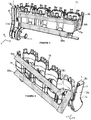
- the figure 1 is a schematic representation of an embodiment of a heat engine 1 comprising a cylinder casing 2a provided with a plurality of cylinders 3, otherwise called stations, which can be arranged in line.
- This cylinder casing 2a of the engine 1 may include nonlimiting and non-exhaustive four cylinders 3 arranged in line.
- This cylinder head cover 2b comprises a lower face which is intended to be fixed on an upper face of the cylinder casing 2a, which is disposed below this cylinder head housing 2b.
- This breech housing 2b includes the distribution mainly composed of valves and camshafts. More specifically, in this cylinder head housing 2b are provided supply or intake ducts and exhaust ducts which are respectively intended for the flow of an air mixture and admitted gas to the cylinders of the engine 1, and the flow of flue gas escaping out of the cylinders 3. These ducts are controlled by valves, and these are actuated by at least one camshaft.
- This engine 1 can be a static engine, a motor of an electric generator. It can also be a motor 1 which is implemented in a vehicle such as a land vehicle including a motor vehicle, or a marine or air vehicle.
- the engine 1 conventionally comprises a crankshaft 6 which rotates about a horizontal axis of the engine 1, pistons which slide in cylinders 3 in reciprocating motions, and rods whose upper ends are connected to the pistons and whose lower ends are connected to this crankshaft 6 via eccentric connections.
- the reciprocating movement of the pistons initiated by the combustion of a mixture of air and fuel in the cylinders 3, thus makes it possible to rotate the crankshaft 6.
- crankshaft 6 of the engine 1 is guided by rotation by bearings which are arranged between each cylinder 3 of the engine 1 and on either side of the cylinder casing 2a typically at the respective outlets 7a, 7b of the crankshaft 6 towards a coupling face 4a and towards a frontage of 4b distribution of the engine 1 on the other hand, which outlets 7a, 7b being visible on the Figures 2 and 3 .
- the coupling face 4a is located at a first end of the engine 1.
- this coupling face 4a is located at the cylinder casing 2a, it can however in other variants be located at the level of the casing 2a.
- the cylinder head 2b. It essentially comprises a transmission assembly comprising a coupling case 8 and a gearbox 9, the coupling case 8 connecting the engine 1 and thus the crankshaft 6 to said gearbox 9.
- This coupling case 8 comprises in a manner known in itself, a flywheel 10 to be fixed on the crankshaft 6 of the engine 1 and a clutch 11 may comprise a clutch mechanism and at least one friction disc.
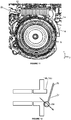
- a casing 12 covering the coupling housing 8 and the gearbox 9 is fixed to the coupling face 4a in particular at a connecting surface 14 having a substantially circular shape and which is visible on the figures 2 and 11 .
- This engine 1 is commonly equipped with a number of peripherals and accessories, among which there may be mentioned an alternator and an air conditioning compressor. These accessories are driven by the operation of the engine 1, via an accessory belt generally connected to a pulley located at the end of a crankshaft 6 of the engine 1, commonly called “crankshaft pulley” and which is arranged at the level of the engine. of the distribution facade 4b.
- This distribution facade 4b also called accessory facade, is located at a second end of the engine 1 being substantially opposite to the coupling face 4a. It essentially comprises pulleys carried by the ends of the crankshaft 6 and a camshaft (or shafts), and the timing belt which transmits to the camshaft the rotation of the crankshaft 6.
- the distribution facade 4b may also include other pulleys on which the timing belt acts. It also has rollers by which the tension and the orientation of the strands of the timing belt are adjusted.
- the engine 1 comprises a heat transfer fluid pump 5 for circulating this fluid in a cooling circuit 15 of the engine 1.
- This pump 5 comprises a pump body 16, a fluid inlet duct 17a and a outlet duct 17b forming a pump volute.
- This pump 5 is intended to circulate via the outlet conduit 17b said coolant or cooling fluid in the cooling circuit 15 of the engine 1.
- this circuit 15 comprises first and second fluid conduits 18a, 18b otherwise called core or fluid chamber.
- Each fluid conduit 18a, 18b is a hollow space or a recess consisting of circulation channels which is defined in the cylinder block 2a or the cylinder head 2b of the engine 1 and in which is intended to circulate this cooling fluid, here some water.
- the fluid inlet 19a of this pump 5 is preferably embedded in the coupling face 4a thereby to have the fluid inlet duct 17a in the coupling face 4a.
- the inlet duct 17a comprises a casing which is mechanically connected to a sealing surface 28 defined at the level of the facade. coupling 4a and in particular an outer skin 29 of this facade 4a.
- This housing may include a convergent.
- the pump body 16 is traversed on either side by a pump shaft 20.
- the shaft 20 is immobilized radially and axially by a ball bearing.
- a ball bearing One could consider a plurality of bearings or a double row ball bearing to ensure the stability and maintenance of the shaft 20 in the pump body 16.
- One end of the shaft 20 supports a blade 21 , or a turbine, adapted to the circulation of the fluid in the cooling circuit 15, the other end comprises a coupling zone 22.
- the blade 21 is secured to the axis for example by a key device well known to those skilled in the art.
- a key device well known to those skilled in the art.
- the water / air seal between the axis 20 and the body 16, intended to prevent the cooling fluid from entering the inside of the pump 5 and damaging the bearing, is provided by a dynamic sealing element 23a for a first variant of the pump 5 illustrated on the figure 9 or two dynamic sealing elements 23a, 23b for a second variant visible on the figure 10 .
- the dynamic sealing element 23a, 23b may be a lip seal and more particularly an O-ring guaranteeing excellent sealing.
- the pump body 16 also comprises an attachment zone 24 provided with at least one O-ring 25 intended to ensure a sealed mechanical connection of the pump 5 in a housing 26 defined in the coupling face 4a of the engine 1, in particular with a wall of this housing 26.
- the pump body 16 also comprises at least one air passage 27 for evacuating by evaporation, the cooling fluid that could penetrate inside the pump 5 despite the presence of the sealing elements 23a, 23b.
- the housing 26 is included in a portion of the coupling face 4a which is defined at the cylinder housing 2a.
- a housing 26 has a shape complementary to that of the pump 5.
- the housing 26 comprises an opening 30 which is defined at a zone 31 of the outer skin 29 of the coupling face 4a. According to the invention, this opening 30 is arranged facing the flywheel 10 of the coupling housing 8.
- the housing 26 and therefore this opening 30 are defined between the connecting surface 14 and an orifice forming the outlet 7a which is formed in the coupling face 4a and which is crossed by an end of the crankshaft 6 provided to be connected to the flywheel 10.
- this housing 26 of the pump 5 is located at a height h1 which extends from the bottom of the oil sump 32 of the engine 1 to the pump 5 which is less than a height h2 between the bottom of the oil sump. oil 32 and the cooling circuit 15 of the engine 1 and in particular the first conduit 18a.
- the pump 5 is located in a lower part of the engine 1 and preferably at a height h1 which positions it at a level which is located below the level of the first conduit 18a relative to the height h2.
- the pump 5 is then constantly in the cooling fluid and this even during filling or refilling after-sales phases as well as in degassing phases of the cooling circuit 15.
- Such a position of the pump 5 makes it possible to avoid failures of the "joint grout" type, in particular during the unfolding of these phases, which may for example result from the presence of a gas bubble and / or the absence of cooling fluid in the circuit 15.
- the blade 21 is oriented towards the opening 30 or towards the outside of the coupling face 4a.
- the coupling zone 22 of the pump 5 is adapted to cooperate directly or indirectly with a drive shaft 33 of the motor 1, said shaft 33 being in kinematic relation with the crankshaft 6. Under these conditions, the pump 5 is therefore arranged in the engine 1 so as to be in kinematic relationship with the crankshaft 6 in particular via said drive shaft 33.
- the drive shaft 33 is preferably a balancing shaft 33 of the engine 1.
- the engine 1 comprises indeed two balancing shafts 33 mounted in rotation about balancing axes parallel and distinct from the motor axis 1. These balancing shafts 33, one of which is visible on the figure 6 , are arranged in tunnels 34 defined in the engine 1. The ends of these tunnels 34 are visible on the Figures 2 and 3 relating respectively to the clutch facings 4a and 4b distribution of the engine 1
- the rotational drive members are connected for each balance shaft 33 at a first end thereof having a drive wheel 35 such as a pulley.
- the body of each of these shafts 33 comprises rolling members 36 selected from balls, needles and rollers.
- One of the two balance shafts 33 constitutes a drive shaft 33 of the pump shaft 20 and comprises for this purpose in a second end a coupling member for providing a kinematic connection with the coupling zone 22 of the pump. 5.
- the coupling zone 22 is adapted to be engaged with the coupling member of the drive shaft 33.
- the housing 26 in which the pump 5 is arranged comprises a bottom which is open because having an orifice, and which opens into the tunnel 34 in which is arranged the balancing shaft 33 for the establishment of a coupling link between the coupling zone 22 and the coupling member of this shaft 33
- this dwelling 26 can therefore be made by machining at the same time or at least with good accuracy with respect to this tunnel 34.
- the coupling connection between the pump 5 and the balancing shaft is simplified because it does not require the use of a complex coupling joint.
- the coupling connection can be made without a coupling joint but only from a screw mechanism of the pump shaft 20 on the balancing shaft 33.
- the engine 1 also comprises a housing 13 for input and output of the coolant circulating in the cooling circuit 15.
- This housing 13 is preferably arranged in the coupling face 4a.
- the housing 13 is positioned between the breech housing 2b and the coupling housing 8, in particular between the breech housing 2b and the connection support 14.
- the housing 13 is connected to an inlet 19a and two outputs 19b, 19c of the cooling circuit 15.
- this housing 13 by centralizing all the inputs and outputs 19a, 19b, 19c of the cooling circuit 15 can allow an implementation of simplified control of multiple circulations of the fluid in the cooling circuit 15.
- the inputs and outputs 19a, 19b, 19c of this circuit are embedded in the coupling face 4a.
- the fluid enters this input of the circuit to be routed to the pump 5 to be then circulated in the first and second conduits 18a, 18b of fluid in the direction of circulation represented by the arrows present on the figures 1 , 4 and 5 .
- each opening / closing element 37 may comprise a flap 38 and a return element 39 such as a spring made of a shape memory material.
- the pump 5 delivers a fluid in a cooling circuit 15 which is simplified in terms of packaging allowing simple or more complex water circulations of all types, thus making it possible to implement modes of operation of the cooling circuit 15 for example in "split cooling” or in single or multiple loop.
Landscapes
- Engineering & Computer Science (AREA)
- Chemical & Material Sciences (AREA)
- Combustion & Propulsion (AREA)
- Mechanical Engineering (AREA)
- General Engineering & Computer Science (AREA)
- Structures Of Non-Positive Displacement Pumps (AREA)
Claims (8)
- Verbrennungsmotor (1), welcher eine Kühlflüssigkeitspumpe (5) umfasst, die dazu bestimmt ist, eine Zirkulation der Kühlflüssigkeit in einem Kühlkreislauf (15) des Motors (1) zu bewirken, wobei die Pumpe (5) in einer Kupplungs-Frontseite (4a) des Motors (1) angeordnet ist, wobei sie mit einer Antriebswelle (33) des Motors (1), insbesondere einer Ausgleichswelle dieses Motors (1), in kinematischer Verbindung steht, wobei die Kupplungs-Frontseite (4a) eine Aufnahme (26) umfasst, in welcher die Pumpe (5) angeordnet ist, dadurch gekennzeichnet, dass die Aufnahme (26) eine Öffnung (30) aufweist, die gegenüber einer Schwungscheibe (10) eines Kupplungsgehäuses (8) des Motors (1) angeordnet ist.
- Motor (1) nach dem vorhergehenden Anspruch, dadurch gekennzeichnet, dass:- die Aufnahme (26) in der Kupplungs-Frontseite (4a) eines Zylindergehäuses (2a) des Motors (1) enthalten ist, und/oder- die Aufnahme (26) einen Boden umfasst, der in einen im Motor (1) vorgesehenen Tunnel (34) zum Aufnehmen der Antriebswelle (33) mündet, und/oder- die Aufnahme (26) eine Öffnung (30) umfasst, die in einer Außenhaut (29) der Kupplungs-Frontseite (4a) definiert ist.
- Motor (1) nach einem der vorhergehenden Ansprüche, dadurch gekennzeichnet, dass eine Aufnahme (26), die geeignet ist, die Pumpe (5) aufzunehmen, auf einer Höhe (h1) definiert ist, welche niedriger als eine Höhe (h2) des Kühlkreislaufs (15) ist.
- Motor (1) nach einem der vorhergehenden Ansprüche, dadurch gekennzeichnet, dass die Pumpe (5) einen Kupplungsbereich (22) umfasst, der dafür eingerichtet ist, mit einem Kupplungsorgan der Antriebswelle (33) in Eingriff zu stehen.
- Motor (1) nach einem der vorhergehenden Ansprüche, dadurch gekennzeichnet, dass er ein mit der Pumpe (5) und mit dem Kühlkreislauf (15) verbundenes Gehäuse (13) für den Eintritt und Austritt der Kühlflüssigkeit umfasst, das an der Kupplungs-Frontseite (4a) angeordnet ist.
- Motor (1) nach einem der vorhergehenden Ansprüche, dadurch gekennzeichnet, dass die Pumpe (5) wenigstens eine dynamische Dichtung umfasst.
- Motor (1) nach einem der vorhergehenden Ansprüche, dadurch gekennzeichnet, dass die Pumpe (5) in kinematischer Verbindung mit einer Kurbelwelle (6) des Motors (1) steht, insbesondere über die Antriebswelle (33).
- Fahrzeug, insbesondere Kraftfahrzeug, welches einen Verbrennungsmotor (1) nach einem der vorhergehenden Ansprüche umfasst.
Applications Claiming Priority (1)
| Application Number | Priority Date | Filing Date | Title |
|---|---|---|---|
| FR1654304A FR3051222B1 (fr) | 2016-05-13 | 2016-05-13 | Moteur thermique comprenant une pompe a fluide caloporteur |
Publications (2)
| Publication Number | Publication Date |
|---|---|
| EP3244034A1 EP3244034A1 (de) | 2017-11-15 |
| EP3244034B1 true EP3244034B1 (de) | 2019-09-11 |
Family
ID=56896678
Family Applications (1)
| Application Number | Title | Priority Date | Filing Date |
|---|---|---|---|
| EP17158620.9A Active EP3244034B1 (de) | 2016-05-13 | 2017-03-01 | Brennkraftmotor mit einer kühlflüssigkeitspumpe |
Country Status (2)
| Country | Link |
|---|---|
| EP (1) | EP3244034B1 (de) |
| FR (1) | FR3051222B1 (de) |
Families Citing this family (1)
| Publication number | Priority date | Publication date | Assignee | Title |
|---|---|---|---|---|
| FR3093135B1 (fr) | 2019-02-26 | 2022-07-08 | Renault Sas | Moteur thermique comprenant une pompe à fluide caloporteur |
Family Cites Families (3)
| Publication number | Priority date | Publication date | Assignee | Title |
|---|---|---|---|---|
| DE102005026786A1 (de) * | 2005-06-10 | 2006-12-21 | Audi Ag | Dichtungsanordnung zwischen einem Ausgleichswellenmodul und einer Pumpenwelle |
| JP5932574B2 (ja) * | 2012-08-31 | 2016-06-08 | 本田技研工業株式会社 | 車両用水冷式内燃機関 |
| DE102014207071B4 (de) * | 2014-04-11 | 2018-09-20 | Volkswagen Aktiengesellschaft | Verbrennungsmotor mit einem Kurbelgehäuse und einer Kühlmittelpumpe |
-
2016
- 2016-05-13 FR FR1654304A patent/FR3051222B1/fr not_active Expired - Fee Related
-
2017
- 2017-03-01 EP EP17158620.9A patent/EP3244034B1/de active Active
Non-Patent Citations (1)
| Title |
|---|
| None * |
Also Published As
| Publication number | Publication date |
|---|---|
| FR3051222A1 (fr) | 2017-11-17 |
| FR3051222B1 (fr) | 2019-10-11 |
| EP3244034A1 (de) | 2017-11-15 |
Similar Documents
| Publication | Publication Date | Title |
|---|---|---|
| FR2609109A1 (fr) | Agencement de charge de support de poussee pour moteur a turbine a gaz | |
| EP1977097B1 (de) | Verbesserungen einer verbrennungskraftmaschine mit variablem verdichtungsverhältnis | |
| EP3011142A1 (de) | Verbessertes zwischengehäuse für eine turbomaschine und hilfsgetriebe-antriebsanordnung | |
| FR3008464A1 (fr) | Transmission de moteur hors-bord | |
| FR3026452A1 (fr) | Reducteur de vitesse a deux lignes intermediaires de transmission | |
| WO2012176037A1 (fr) | Moteur a combustion interne avec transmission a calage variable | |
| FR2783282A1 (fr) | Structure de lubrification pour moteur a quatre temps | |
| FR3108068A1 (fr) | Double embrayage humide | |
| FR3051222B1 (fr) | Moteur thermique comprenant une pompe a fluide caloporteur | |
| CA2492844C (fr) | Actionneur hydraulique de soupapes pour moteur a pistons | |
| FR2577615A1 (fr) | Circuit de graissage pour un moteur a arbre vertical | |
| JP2009097350A (ja) | エンジン | |
| WO2013188932A2 (fr) | Système de distribution directe pour moteur a combustion interne | |
| FR3074773A1 (fr) | Dispositif de propulsion d’un engin marin de navigation et engin marin de navigation pourvu d’un tel dispositif | |
| FR2844311A1 (fr) | Appareil d'actionnement de pompe a air | |
| FR3069576A1 (fr) | Moteur avec un arbre d'entrainement integre et une trappe d'acces a cet arbre | |
| FR3135500A1 (fr) | Réducteur de vitesse de groupe motopropulseur hybride | |
| FR3093135A1 (fr) | Moteur thermique comprenant une pompe à fluide caloporteur | |
| EP4180681B1 (de) | Verbesserte nasskupplung für ein motorisiertes antriebssystem | |
| FR3108943A1 (fr) | Boitier d’engrenages pour turbomachine, turbomachine associée | |
| WO2004031538A1 (fr) | Moteur a pistons alternatifs | |
| FR2628479A1 (fr) | Assemblage piston et cylindre a mouvement alternatif pour moteurs a combustion interne et equivalent | |
| FR2501783A1 (fr) | Moteurs thermiques rotatifs et compresseurs | |
| FR3118942A1 (fr) | Soufflante a calage variable | |
| FR3044039B1 (fr) | Systeme de decalage en rotation entre deux arbres montes mobiles en rotation . |
Legal Events
| Date | Code | Title | Description |
|---|---|---|---|
| PUAI | Public reference made under article 153(3) epc to a published international application that has entered the european phase |
Free format text: ORIGINAL CODE: 0009012 |
|
| STAA | Information on the status of an ep patent application or granted ep patent |
Free format text: STATUS: THE APPLICATION HAS BEEN PUBLISHED |
|
| AK | Designated contracting states |
Kind code of ref document: A1 Designated state(s): AL AT BE BG CH CY CZ DE DK EE ES FI FR GB GR HR HU IE IS IT LI LT LU LV MC MK MT NL NO PL PT RO RS SE SI SK SM TR |
|
| AX | Request for extension of the european patent |
Extension state: BA ME |
|
| STAA | Information on the status of an ep patent application or granted ep patent |
Free format text: STATUS: REQUEST FOR EXAMINATION WAS MADE |
|
| 17P | Request for examination filed |
Effective date: 20180530 |
|
| RBV | Designated contracting states (corrected) |
Designated state(s): AL AT BE BG CH CY CZ DE DK EE ES FI FR GB GR HR HU IE IS IT LI LT LU LV MC MK MT NL NO PL PT RO RS SE SI SK SM TR |
|
| STAA | Information on the status of an ep patent application or granted ep patent |
Free format text: STATUS: EXAMINATION IS IN PROGRESS |
|
| 17Q | First examination report despatched |
Effective date: 20181002 |
|
| GRAP | Despatch of communication of intention to grant a patent |
Free format text: ORIGINAL CODE: EPIDOSNIGR1 |
|
| STAA | Information on the status of an ep patent application or granted ep patent |
Free format text: STATUS: GRANT OF PATENT IS INTENDED |
|
| INTG | Intention to grant announced |
Effective date: 20190503 |
|
| GRAS | Grant fee paid |
Free format text: ORIGINAL CODE: EPIDOSNIGR3 |
|
| GRAA | (expected) grant |
Free format text: ORIGINAL CODE: 0009210 |
|
| STAA | Information on the status of an ep patent application or granted ep patent |
Free format text: STATUS: THE PATENT HAS BEEN GRANTED |
|
| AK | Designated contracting states |
Kind code of ref document: B1 Designated state(s): AL AT BE BG CH CY CZ DE DK EE ES FI FR GB GR HR HU IE IS IT LI LT LU LV MC MK MT NL NO PL PT RO RS SE SI SK SM TR |
|
| REG | Reference to a national code |
Ref country code: GB Ref legal event code: FG4D Free format text: NOT ENGLISH |
|
| REG | Reference to a national code |
Ref country code: CH Ref legal event code: EP |
|
| REG | Reference to a national code |
Ref country code: AT Ref legal event code: REF Ref document number: 1178738 Country of ref document: AT Kind code of ref document: T Effective date: 20190915 |
|
| REG | Reference to a national code |
Ref country code: DE Ref legal event code: R096 Ref document number: 602017006837 Country of ref document: DE Ref country code: IE Ref legal event code: FG4D Free format text: LANGUAGE OF EP DOCUMENT: FRENCH |
|
| REG | Reference to a national code |
Ref country code: NL Ref legal event code: MP Effective date: 20190911 |
|
| REG | Reference to a national code |
Ref country code: LT Ref legal event code: MG4D |
|
| PG25 | Lapsed in a contracting state [announced via postgrant information from national office to epo] |
Ref country code: SE Free format text: LAPSE BECAUSE OF FAILURE TO SUBMIT A TRANSLATION OF THE DESCRIPTION OR TO PAY THE FEE WITHIN THE PRESCRIBED TIME-LIMIT Effective date: 20190911 Ref country code: NO Free format text: LAPSE BECAUSE OF FAILURE TO SUBMIT A TRANSLATION OF THE DESCRIPTION OR TO PAY THE FEE WITHIN THE PRESCRIBED TIME-LIMIT Effective date: 20191211 Ref country code: FI Free format text: LAPSE BECAUSE OF FAILURE TO SUBMIT A TRANSLATION OF THE DESCRIPTION OR TO PAY THE FEE WITHIN THE PRESCRIBED TIME-LIMIT Effective date: 20190911 Ref country code: BG Free format text: LAPSE BECAUSE OF FAILURE TO SUBMIT A TRANSLATION OF THE DESCRIPTION OR TO PAY THE FEE WITHIN THE PRESCRIBED TIME-LIMIT Effective date: 20191211 Ref country code: HR Free format text: LAPSE BECAUSE OF FAILURE TO SUBMIT A TRANSLATION OF THE DESCRIPTION OR TO PAY THE FEE WITHIN THE PRESCRIBED TIME-LIMIT Effective date: 20190911 Ref country code: LT Free format text: LAPSE BECAUSE OF FAILURE TO SUBMIT A TRANSLATION OF THE DESCRIPTION OR TO PAY THE FEE WITHIN THE PRESCRIBED TIME-LIMIT Effective date: 20190911 |
|
| PG25 | Lapsed in a contracting state [announced via postgrant information from national office to epo] |
Ref country code: RS Free format text: LAPSE BECAUSE OF FAILURE TO SUBMIT A TRANSLATION OF THE DESCRIPTION OR TO PAY THE FEE WITHIN THE PRESCRIBED TIME-LIMIT Effective date: 20190911 Ref country code: LV Free format text: LAPSE BECAUSE OF FAILURE TO SUBMIT A TRANSLATION OF THE DESCRIPTION OR TO PAY THE FEE WITHIN THE PRESCRIBED TIME-LIMIT Effective date: 20190911 Ref country code: AL Free format text: LAPSE BECAUSE OF FAILURE TO SUBMIT A TRANSLATION OF THE DESCRIPTION OR TO PAY THE FEE WITHIN THE PRESCRIBED TIME-LIMIT Effective date: 20190911 Ref country code: ES Free format text: LAPSE BECAUSE OF FAILURE TO SUBMIT A TRANSLATION OF THE DESCRIPTION OR TO PAY THE FEE WITHIN THE PRESCRIBED TIME-LIMIT Effective date: 20190911 Ref country code: GR Free format text: LAPSE BECAUSE OF FAILURE TO SUBMIT A TRANSLATION OF THE DESCRIPTION OR TO PAY THE FEE WITHIN THE PRESCRIBED TIME-LIMIT Effective date: 20191212 |
|
| REG | Reference to a national code |
Ref country code: AT Ref legal event code: MK05 Ref document number: 1178738 Country of ref document: AT Kind code of ref document: T Effective date: 20190911 |
|
| PG25 | Lapsed in a contracting state [announced via postgrant information from national office to epo] |
Ref country code: PL Free format text: LAPSE BECAUSE OF FAILURE TO SUBMIT A TRANSLATION OF THE DESCRIPTION OR TO PAY THE FEE WITHIN THE PRESCRIBED TIME-LIMIT Effective date: 20190911 Ref country code: NL Free format text: LAPSE BECAUSE OF FAILURE TO SUBMIT A TRANSLATION OF THE DESCRIPTION OR TO PAY THE FEE WITHIN THE PRESCRIBED TIME-LIMIT Effective date: 20190911 Ref country code: PT Free format text: LAPSE BECAUSE OF FAILURE TO SUBMIT A TRANSLATION OF THE DESCRIPTION OR TO PAY THE FEE WITHIN THE PRESCRIBED TIME-LIMIT Effective date: 20200113 Ref country code: RO Free format text: LAPSE BECAUSE OF FAILURE TO SUBMIT A TRANSLATION OF THE DESCRIPTION OR TO PAY THE FEE WITHIN THE PRESCRIBED TIME-LIMIT Effective date: 20190911 Ref country code: AT Free format text: LAPSE BECAUSE OF FAILURE TO SUBMIT A TRANSLATION OF THE DESCRIPTION OR TO PAY THE FEE WITHIN THE PRESCRIBED TIME-LIMIT Effective date: 20190911 Ref country code: IT Free format text: LAPSE BECAUSE OF FAILURE TO SUBMIT A TRANSLATION OF THE DESCRIPTION OR TO PAY THE FEE WITHIN THE PRESCRIBED TIME-LIMIT Effective date: 20190911 Ref country code: EE Free format text: LAPSE BECAUSE OF FAILURE TO SUBMIT A TRANSLATION OF THE DESCRIPTION OR TO PAY THE FEE WITHIN THE PRESCRIBED TIME-LIMIT Effective date: 20190911 |
|
| PG25 | Lapsed in a contracting state [announced via postgrant information from national office to epo] |
Ref country code: SM Free format text: LAPSE BECAUSE OF FAILURE TO SUBMIT A TRANSLATION OF THE DESCRIPTION OR TO PAY THE FEE WITHIN THE PRESCRIBED TIME-LIMIT Effective date: 20190911 Ref country code: CZ Free format text: LAPSE BECAUSE OF FAILURE TO SUBMIT A TRANSLATION OF THE DESCRIPTION OR TO PAY THE FEE WITHIN THE PRESCRIBED TIME-LIMIT Effective date: 20190911 Ref country code: SK Free format text: LAPSE BECAUSE OF FAILURE TO SUBMIT A TRANSLATION OF THE DESCRIPTION OR TO PAY THE FEE WITHIN THE PRESCRIBED TIME-LIMIT Effective date: 20190911 Ref country code: IS Free format text: LAPSE BECAUSE OF FAILURE TO SUBMIT A TRANSLATION OF THE DESCRIPTION OR TO PAY THE FEE WITHIN THE PRESCRIBED TIME-LIMIT Effective date: 20200224 |
|
| REG | Reference to a national code |
Ref country code: DE Ref legal event code: R097 Ref document number: 602017006837 Country of ref document: DE |
|
| PLBE | No opposition filed within time limit |
Free format text: ORIGINAL CODE: 0009261 |
|
| STAA | Information on the status of an ep patent application or granted ep patent |
Free format text: STATUS: NO OPPOSITION FILED WITHIN TIME LIMIT |
|
| PG2D | Information on lapse in contracting state deleted |
Ref country code: IS |
|
| PG25 | Lapsed in a contracting state [announced via postgrant information from national office to epo] |
Ref country code: DK Free format text: LAPSE BECAUSE OF FAILURE TO SUBMIT A TRANSLATION OF THE DESCRIPTION OR TO PAY THE FEE WITHIN THE PRESCRIBED TIME-LIMIT Effective date: 20190911 Ref country code: IS Free format text: LAPSE BECAUSE OF FAILURE TO SUBMIT A TRANSLATION OF THE DESCRIPTION OR TO PAY THE FEE WITHIN THE PRESCRIBED TIME-LIMIT Effective date: 20200112 |
|
| 26N | No opposition filed |
Effective date: 20200615 |
|
| PG25 | Lapsed in a contracting state [announced via postgrant information from national office to epo] |
Ref country code: SI Free format text: LAPSE BECAUSE OF FAILURE TO SUBMIT A TRANSLATION OF THE DESCRIPTION OR TO PAY THE FEE WITHIN THE PRESCRIBED TIME-LIMIT Effective date: 20190911 |
|
| PG25 | Lapsed in a contracting state [announced via postgrant information from national office to epo] |
Ref country code: MC Free format text: LAPSE BECAUSE OF FAILURE TO SUBMIT A TRANSLATION OF THE DESCRIPTION OR TO PAY THE FEE WITHIN THE PRESCRIBED TIME-LIMIT Effective date: 20190911 |
|
| REG | Reference to a national code |
Ref country code: CH Ref legal event code: PL |
|
| REG | Reference to a national code |
Ref country code: BE Ref legal event code: MM Effective date: 20200331 |
|
| PG25 | Lapsed in a contracting state [announced via postgrant information from national office to epo] |
Ref country code: LU Free format text: LAPSE BECAUSE OF NON-PAYMENT OF DUE FEES Effective date: 20200301 |
|
| PG25 | Lapsed in a contracting state [announced via postgrant information from national office to epo] |
Ref country code: CH Free format text: LAPSE BECAUSE OF NON-PAYMENT OF DUE FEES Effective date: 20200331 Ref country code: IE Free format text: LAPSE BECAUSE OF NON-PAYMENT OF DUE FEES Effective date: 20200301 Ref country code: LI Free format text: LAPSE BECAUSE OF NON-PAYMENT OF DUE FEES Effective date: 20200331 |
|
| PG25 | Lapsed in a contracting state [announced via postgrant information from national office to epo] |
Ref country code: BE Free format text: LAPSE BECAUSE OF NON-PAYMENT OF DUE FEES Effective date: 20200331 |
|
| GBPC | Gb: european patent ceased through non-payment of renewal fee |
Effective date: 20210301 |
|
| PG25 | Lapsed in a contracting state [announced via postgrant information from national office to epo] |
Ref country code: GB Free format text: LAPSE BECAUSE OF NON-PAYMENT OF DUE FEES Effective date: 20210301 |
|
| PG25 | Lapsed in a contracting state [announced via postgrant information from national office to epo] |
Ref country code: TR Free format text: LAPSE BECAUSE OF FAILURE TO SUBMIT A TRANSLATION OF THE DESCRIPTION OR TO PAY THE FEE WITHIN THE PRESCRIBED TIME-LIMIT Effective date: 20190911 Ref country code: MT Free format text: LAPSE BECAUSE OF FAILURE TO SUBMIT A TRANSLATION OF THE DESCRIPTION OR TO PAY THE FEE WITHIN THE PRESCRIBED TIME-LIMIT Effective date: 20190911 Ref country code: CY Free format text: LAPSE BECAUSE OF FAILURE TO SUBMIT A TRANSLATION OF THE DESCRIPTION OR TO PAY THE FEE WITHIN THE PRESCRIBED TIME-LIMIT Effective date: 20190911 |
|
| PG25 | Lapsed in a contracting state [announced via postgrant information from national office to epo] |
Ref country code: MK Free format text: LAPSE BECAUSE OF FAILURE TO SUBMIT A TRANSLATION OF THE DESCRIPTION OR TO PAY THE FEE WITHIN THE PRESCRIBED TIME-LIMIT Effective date: 20190911 |
|
| P01 | Opt-out of the competence of the unified patent court (upc) registered |
Effective date: 20230608 |
|
| REG | Reference to a national code |
Ref country code: DE Ref legal event code: R081 Ref document number: 602017006837 Country of ref document: DE Owner name: NEW H POWERTRAIN HOLDING, S.L.U., ES Free format text: FORMER OWNER: RENAULT S.A.S., BOULOGNE-BILLANCOURT, FR |
|
| PGFP | Annual fee paid to national office [announced via postgrant information from national office to epo] |
Ref country code: DE Payment date: 20260319 Year of fee payment: 10 |
|
| PGFP | Annual fee paid to national office [announced via postgrant information from national office to epo] |
Ref country code: FR Payment date: 20260320 Year of fee payment: 10 |