EP3244043B1 - Vorrichtung und verfahren zur steuerung eines agr-ventils - Google Patents
Vorrichtung und verfahren zur steuerung eines agr-ventils Download PDFInfo
- Publication number
- EP3244043B1 EP3244043B1 EP16735202.0A EP16735202A EP3244043B1 EP 3244043 B1 EP3244043 B1 EP 3244043B1 EP 16735202 A EP16735202 A EP 16735202A EP 3244043 B1 EP3244043 B1 EP 3244043B1
- Authority
- EP
- European Patent Office
- Prior art keywords
- fresh air
- engine system
- operation condition
- amount
- output
- Prior art date
- Legal status (The legal status is an assumption and is not a legal conclusion. Google has not performed a legal analysis and makes no representation as to the accuracy of the status listed.)
- Not-in-force
Links
Images





Classifications
-
- F—MECHANICAL ENGINEERING; LIGHTING; HEATING; WEAPONS; BLASTING
- F02—COMBUSTION ENGINES; HOT-GAS OR COMBUSTION-PRODUCT ENGINE PLANTS
- F02D—CONTROLLING COMBUSTION ENGINES
- F02D21/00—Controlling engines characterised by their being supplied with non-airborne oxygen or other non-fuel gas
- F02D21/06—Controlling engines characterised by their being supplied with non-airborne oxygen or other non-fuel gas peculiar to engines having other non-fuel gas added to combustion air
- F02D21/08—Controlling engines characterised by their being supplied with non-airborne oxygen or other non-fuel gas peculiar to engines having other non-fuel gas added to combustion air the other gas being the exhaust gas of engine
-
- F—MECHANICAL ENGINEERING; LIGHTING; HEATING; WEAPONS; BLASTING
- F02—COMBUSTION ENGINES; HOT-GAS OR COMBUSTION-PRODUCT ENGINE PLANTS
- F02D—CONTROLLING COMBUSTION ENGINES
- F02D41/00—Electrical control of supply of combustible mixture or its constituents
- F02D41/0025—Controlling engines characterised by use of non-liquid fuels, pluralities of fuels, or non-fuel substances added to the combustible mixtures
- F02D41/0047—Controlling exhaust gas recirculation [EGR]
- F02D41/0077—Control of the EGR valve or actuator, e.g. duty cycle, closed loop control of position
-
- F—MECHANICAL ENGINEERING; LIGHTING; HEATING; WEAPONS; BLASTING
- F02—COMBUSTION ENGINES; HOT-GAS OR COMBUSTION-PRODUCT ENGINE PLANTS
- F02D—CONTROLLING COMBUSTION ENGINES
- F02D41/00—Electrical control of supply of combustible mixture or its constituents
- F02D41/0002—Controlling intake air
-
- F—MECHANICAL ENGINEERING; LIGHTING; HEATING; WEAPONS; BLASTING
- F02—COMBUSTION ENGINES; HOT-GAS OR COMBUSTION-PRODUCT ENGINE PLANTS
- F02D—CONTROLLING COMBUSTION ENGINES
- F02D41/00—Electrical control of supply of combustible mixture or its constituents
- F02D41/0025—Controlling engines characterised by use of non-liquid fuels, pluralities of fuels, or non-fuel substances added to the combustible mixtures
- F02D41/0047—Controlling exhaust gas recirculation [EGR]
- F02D41/005—Controlling exhaust gas recirculation [EGR] according to engine operating conditions
- F02D41/0052—Feedback control of engine parameters, e.g. for control of air/fuel ratio or intake air amount
-
- F—MECHANICAL ENGINEERING; LIGHTING; HEATING; WEAPONS; BLASTING
- F02—COMBUSTION ENGINES; HOT-GAS OR COMBUSTION-PRODUCT ENGINE PLANTS
- F02D—CONTROLLING COMBUSTION ENGINES
- F02D41/00—Electrical control of supply of combustible mixture or its constituents
- F02D41/02—Circuit arrangements for generating control signals
- F02D41/14—Introducing closed-loop corrections
- F02D41/1401—Introducing closed-loop corrections characterised by the control or regulation method
- F02D41/1402—Adaptive control
-
- F—MECHANICAL ENGINEERING; LIGHTING; HEATING; WEAPONS; BLASTING
- F02—COMBUSTION ENGINES; HOT-GAS OR COMBUSTION-PRODUCT ENGINE PLANTS
- F02D—CONTROLLING COMBUSTION ENGINES
- F02D41/00—Electrical control of supply of combustible mixture or its constituents
- F02D41/02—Circuit arrangements for generating control signals
- F02D41/14—Introducing closed-loop corrections
- F02D41/1401—Introducing closed-loop corrections characterised by the control or regulation method
- F02D41/1405—Neural network control
-
- F—MECHANICAL ENGINEERING; LIGHTING; HEATING; WEAPONS; BLASTING
- F02—COMBUSTION ENGINES; HOT-GAS OR COMBUSTION-PRODUCT ENGINE PLANTS
- F02D—CONTROLLING COMBUSTION ENGINES
- F02D41/00—Electrical control of supply of combustible mixture or its constituents
- F02D41/02—Circuit arrangements for generating control signals
- F02D41/18—Circuit arrangements for generating control signals by measuring intake air flow
-
- F—MECHANICAL ENGINEERING; LIGHTING; HEATING; WEAPONS; BLASTING
- F02—COMBUSTION ENGINES; HOT-GAS OR COMBUSTION-PRODUCT ENGINE PLANTS
- F02M—SUPPLYING COMBUSTION ENGINES IN GENERAL WITH COMBUSTIBLE MIXTURES OR CONSTITUENTS THEREOF
- F02M26/00—Engine-pertinent apparatus for adding exhaust gases to combustion-air, main fuel or fuel-air mixture, e.g. by exhaust gas recirculation [EGR] systems
- F02M26/45—Sensors specially adapted for EGR systems
-
- F—MECHANICAL ENGINEERING; LIGHTING; HEATING; WEAPONS; BLASTING
- F02—COMBUSTION ENGINES; HOT-GAS OR COMBUSTION-PRODUCT ENGINE PLANTS
- F02M—SUPPLYING COMBUSTION ENGINES IN GENERAL WITH COMBUSTIBLE MIXTURES OR CONSTITUENTS THEREOF
- F02M26/00—Engine-pertinent apparatus for adding exhaust gases to combustion-air, main fuel or fuel-air mixture, e.g. by exhaust gas recirculation [EGR] systems
- F02M26/45—Sensors specially adapted for EGR systems
- F02M26/46—Sensors specially adapted for EGR systems for determining the characteristics of gases, e.g. composition
-
- F—MECHANICAL ENGINEERING; LIGHTING; HEATING; WEAPONS; BLASTING
- F02—COMBUSTION ENGINES; HOT-GAS OR COMBUSTION-PRODUCT ENGINE PLANTS
- F02M—SUPPLYING COMBUSTION ENGINES IN GENERAL WITH COMBUSTIBLE MIXTURES OR CONSTITUENTS THEREOF
- F02M26/00—Engine-pertinent apparatus for adding exhaust gases to combustion-air, main fuel or fuel-air mixture, e.g. by exhaust gas recirculation [EGR] systems
- F02M26/52—Systems for actuating EGR valves
-
- F—MECHANICAL ENGINEERING; LIGHTING; HEATING; WEAPONS; BLASTING
- F02—COMBUSTION ENGINES; HOT-GAS OR COMBUSTION-PRODUCT ENGINE PLANTS
- F02D—CONTROLLING COMBUSTION ENGINES
- F02D21/00—Controlling engines characterised by their being supplied with non-airborne oxygen or other non-fuel gas
- F02D21/06—Controlling engines characterised by their being supplied with non-airborne oxygen or other non-fuel gas peculiar to engines having other non-fuel gas added to combustion air
- F02D21/08—Controlling engines characterised by their being supplied with non-airborne oxygen or other non-fuel gas peculiar to engines having other non-fuel gas added to combustion air the other gas being the exhaust gas of engine
- F02D2021/083—Controlling engines characterised by their being supplied with non-airborne oxygen or other non-fuel gas peculiar to engines having other non-fuel gas added to combustion air the other gas being the exhaust gas of engine controlling exhaust gas recirculation electronically
-
- F—MECHANICAL ENGINEERING; LIGHTING; HEATING; WEAPONS; BLASTING
- F02—COMBUSTION ENGINES; HOT-GAS OR COMBUSTION-PRODUCT ENGINE PLANTS
- F02D—CONTROLLING COMBUSTION ENGINES
- F02D41/00—Electrical control of supply of combustible mixture or its constituents
- F02D41/02—Circuit arrangements for generating control signals
- F02D41/14—Introducing closed-loop corrections
- F02D41/1401—Introducing closed-loop corrections characterised by the control or regulation method
- F02D2041/1409—Introducing closed-loop corrections characterised by the control or regulation method using at least a proportional, integral or derivative controller
-
- F—MECHANICAL ENGINEERING; LIGHTING; HEATING; WEAPONS; BLASTING
- F02—COMBUSTION ENGINES; HOT-GAS OR COMBUSTION-PRODUCT ENGINE PLANTS
- F02D—CONTROLLING COMBUSTION ENGINES
- F02D41/00—Electrical control of supply of combustible mixture or its constituents
- F02D41/02—Circuit arrangements for generating control signals
- F02D41/14—Introducing closed-loop corrections
- F02D41/1401—Introducing closed-loop corrections characterised by the control or regulation method
- F02D2041/1413—Controller structures or design
- F02D2041/1422—Variable gain or coefficients
-
- F—MECHANICAL ENGINEERING; LIGHTING; HEATING; WEAPONS; BLASTING
- F02—COMBUSTION ENGINES; HOT-GAS OR COMBUSTION-PRODUCT ENGINE PLANTS
- F02D—CONTROLLING COMBUSTION ENGINES
- F02D41/00—Electrical control of supply of combustible mixture or its constituents
- F02D41/02—Circuit arrangements for generating control signals
- F02D41/14—Introducing closed-loop corrections
- F02D41/1401—Introducing closed-loop corrections characterised by the control or regulation method
- F02D2041/1413—Controller structures or design
- F02D2041/1423—Identification of model or controller parameters
-
- F—MECHANICAL ENGINEERING; LIGHTING; HEATING; WEAPONS; BLASTING
- F02—COMBUSTION ENGINES; HOT-GAS OR COMBUSTION-PRODUCT ENGINE PLANTS
- F02D—CONTROLLING COMBUSTION ENGINES
- F02D41/00—Electrical control of supply of combustible mixture or its constituents
- F02D41/02—Circuit arrangements for generating control signals
- F02D41/14—Introducing closed-loop corrections
- F02D41/1401—Introducing closed-loop corrections characterised by the control or regulation method
- F02D2041/1413—Controller structures or design
- F02D2041/1431—Controller structures or design the system including an input-output delay
-
- F—MECHANICAL ENGINEERING; LIGHTING; HEATING; WEAPONS; BLASTING
- F02—COMBUSTION ENGINES; HOT-GAS OR COMBUSTION-PRODUCT ENGINE PLANTS
- F02D—CONTROLLING COMBUSTION ENGINES
- F02D41/00—Electrical control of supply of combustible mixture or its constituents
- F02D41/02—Circuit arrangements for generating control signals
- F02D41/14—Introducing closed-loop corrections
- F02D41/1401—Introducing closed-loop corrections characterised by the control or regulation method
- F02D2041/1433—Introducing closed-loop corrections characterised by the control or regulation method using a model or simulation of the system
- F02D2041/1437—Simulation
-
- F—MECHANICAL ENGINEERING; LIGHTING; HEATING; WEAPONS; BLASTING
- F02—COMBUSTION ENGINES; HOT-GAS OR COMBUSTION-PRODUCT ENGINE PLANTS
- F02M—SUPPLYING COMBUSTION ENGINES IN GENERAL WITH COMBUSTIBLE MIXTURES OR CONSTITUENTS THEREOF
- F02M26/00—Engine-pertinent apparatus for adding exhaust gases to combustion-air, main fuel or fuel-air mixture, e.g. by exhaust gas recirculation [EGR] systems
- F02M2026/001—Arrangements; Control features; Details
-
- F—MECHANICAL ENGINEERING; LIGHTING; HEATING; WEAPONS; BLASTING
- F02—COMBUSTION ENGINES; HOT-GAS OR COMBUSTION-PRODUCT ENGINE PLANTS
- F02M—SUPPLYING COMBUSTION ENGINES IN GENERAL WITH COMBUSTIBLE MIXTURES OR CONSTITUENTS THEREOF
- F02M26/00—Engine-pertinent apparatus for adding exhaust gases to combustion-air, main fuel or fuel-air mixture, e.g. by exhaust gas recirculation [EGR] systems
- F02M2026/001—Arrangements; Control features; Details
- F02M2026/003—EGR valve controlled by air measuring device
-
- Y—GENERAL TAGGING OF NEW TECHNOLOGICAL DEVELOPMENTS; GENERAL TAGGING OF CROSS-SECTIONAL TECHNOLOGIES SPANNING OVER SEVERAL SECTIONS OF THE IPC; TECHNICAL SUBJECTS COVERED BY FORMER USPC CROSS-REFERENCE ART COLLECTIONS [XRACs] AND DIGESTS
- Y02—TECHNOLOGIES OR APPLICATIONS FOR MITIGATION OR ADAPTATION AGAINST CLIMATE CHANGE
- Y02T—CLIMATE CHANGE MITIGATION TECHNOLOGIES RELATED TO TRANSPORTATION
- Y02T10/00—Road transport of goods or passengers
- Y02T10/10—Internal combustion engine [ICE] based vehicles
- Y02T10/40—Engine management systems
Definitions
- the present invention relates to a control apparatus and a control method, and more particularly, to an apparatus and a method for controlling an EGR valve.
- Exhaust gas discharged from an engine contains a large amount of hazardous substances such as CO, HC, and NOx. Focus on the serious problem of air pollution caused by the exhaust gas discharged from the engine has become urgent, and thus exhaust gas emission regulations have become stricter in many countries. To meet the exhaust gas emission regulations in each country, many methods and apparatuses for purifying exhaust gas have been proposed, and particularly, many efforts have been made in order to remove NOx which is known as a substance that greatly affects the air pollution among the substances contained in the exhaust gas discharged from a vehicle. As one method, recently, exhaust gas recirculation (EGR) is widely used.
- EGR exhaust gas recirculation
- An EGR apparatus includes an EGR line that extends from an exhaust line of the engine to an intake line of the engine, and an EGR valve is provided in the EGR line in order to adjust the amount of exhaust gas recirculated and introduced into the intake line in accordance with an operation condition.
- the EGR valve adjusts the amount of exhaust gas recirculated into the intake line by adjusting an opening degree of the EGR line.
- PI control or PID control is used to adjust the opening degree of the EGR line by controlling an operation of the EGR valve by combining proportional control, integral control, and differential control.
- control may be expressed as a control function, and the control function includes control parameters such as a proportional gain K p , an integral gain Ki, and a differential gain Kd.
- Optimized gains which are adjusted in accordance with various operation conditions, are required to improve responsiveness of the engine and ensure stable behavior of the engine.
- the gains are generally used only for the designated engine, and as a result, there is a problem in that a lot of effort needs to be made to set a new gain and adapt the new gain to an operation condition even though the engine is slightly changed.
- the present disclosure has been made in an effort to solve the aforementioned problems in the related art, and an object of the present disclosure is to provide an apparatus and a method for controlling an EGR valve, which are capable of being efficiently set to enable optimized control of the EGR valve even under various operation conditions.
- the apparatus includes: a measurement unit configured to measure at least one operation condition of an engine system; a fresh air amount setting unit configured to set a target amount of fresh air based on the operation condition; a fresh air amount sensor configured to measure a current amount of fresh air introduced through an intake line; an identifier configured to simulate an input and an output of the engine system, and output engine system input-output sensitivity which is a ratio of a change rate of the current amount of fresh air to a change rate of the opening degree of the EGR valve; a gain setting unit configured to set at least one gain according to an operation condition of the engine system; and a control calculation unit configured to correct the gain in accordance with the operation condition of the engine system by dividing the gain by the engine system input-output sensitivity, compare the target amount of fresh air with the current amount of fresh air to calculate an error rate, and use the corrected gain and the calculated control error for its calculations to output a control signal
- the operation condition may include at least one of a rotational speed of an engine, a fuel injection amount, and a boost pressure, which affect a change in amount of fresh air, and wherein the operation condition is inputted to the identifier.
- the identifier may be a neural network model.
- the target amount of fresh air may be obtained by inputting the operation condition to a lookup table.
- the present invention also provides a method of controlling an EGR valve in accordance with claim 8.
- the method includes: measuring an operation condition of an engine system and a current amount of fresh air; setting a target amount of fresh air based on the operation condition; calculating, based on the operation condition, engine system input-output sensitivity which is a ratio of a change rate of the current amount of fresh air to a change rate of an opening degree of the EGR valve, wherein calculating the engine system input-output sensitivity comprises simulating an input and an output of the engine system; calculating a control error by comparing the target amount of fresh air with the current amount of fresh air; setting at least one gain according to an operation condition of the engine system; correcting the gain in accordance with the operation condition of an engine system by dividing the gain by the engine system input-output sensitivity; using the corrected gain and the calculated control error for controlling the opening degree of the EGR valve so that the current amount of fresh air follows the target amount of fresh air.
- the operation condition may include a rotational speed of an engine, a fuel injection amount, and the boost pressure.
- the setting of the target amount of fresh air may include obtaining the target amount of fresh air by inputting the operation condition to a lookup table.
- engine system input-output sensitivity is outputted by an identifier for simulating behavior of the engine system, and a gain of the EGR valve controller is automatically corrected based on the sensitivity, such that the EGR system may be simply constructed at low costs.
- FIG. 1 is a configuration view of an engine system to which an apparatus for controlling an EGR valve according to an exemplary embodiment of the present disclosure is applied
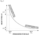
- FIG. 2 is a graph illustrating an example of a relationship between an amount of fresh air introduced into an engine and an opening degree of an EGR valve of the engine system to which the apparatus for controlling the EGR valve according to the exemplary embodiment of the present disclosure is applied
- FIG. 3 is a configuration view of an EGR valve opening degree control unit according to the exemplary embodiment of the present disclosure
- FIG. 4 is a view illustrating an operating state of an identifier of the apparatus for controlling the EGR valve according to the exemplary embodiment of the present disclosure.
- an apparatus for controlling an EGR valve may be applied to an engine system 10 provided with an EGR system.
- the engine system 10 may include an engine block 11 which includes a combustion chamber, an intake line 12 which is connected to an intake port of the engine block 11 so that fresh air (ambient air) is introduced into the intake line 12, an exhaust line 14 which is connected to an exhaust port of the engine block 11 so that exhaust gas is introduced into the exhaust line 14, an EGR line 16 which diverges from the exhaust line 14 and is connected to the intake line 12, and an EGR valve 18 which is positioned in the EGR line 16 and adjusts an opening degree of the EGR line 16.
- the apparatus for controlling the EGR valve includes a measurement unit which measures at least one operation condition of the engine system 10, a fresh air amount sensor 22 which measures a current amount y of fresh air introduced through the intake line 12, an EGR valve sensor 29 which detects an opening degree of the EGR valve, and an EGR valve opening degree control unit 20 which sets a target amount r of fresh air based on an operation condition and controls an opening degree u of the EGR valve so that the current amount y of fresh air follows the target amount r of fresh air.
- the value measured by the EGR valve sensor 29 may be transmitted to the EGR valve opening degree control unit 20.
- the opening degree u of the EGR valve and the amount y of fresh air have a nonlinear relationship, and there are sections where engine system input-output sensitivity ⁇ y/ ⁇ u is high and low, that is, there are sections where a change in amount of fresh air is relatively large and small with respect to the same change in opening degree of the EGR valve.
- gains which are used for controlling and calculating operations of the EGR valve opening degree control unit 20, need to be corrected corresponding to a driving state of the engine system.
- an identifier 60 is adopted to control the opening degree of the EGR valve under various operation conditions. The identifier 60 will be described in detail below.
- the measurement unit measures at least one of various operation conditions of the engine system 10 and transmits the measured operation condition to the EGR valve opening degree control unit 20.
- the operation conditions of the engine system 10 may include various information related to driving of the engine, such as a rotational speed of the engine, a fuel injection amount, boost pressure, and pressure and temperature of intake and exhaust manifolds.
- the measurement unit may include an engine rotational speed sensor 24, a fuel injection amount sensor 26, a boost pressure sensor 28, a temperature sensor, and the like in order to measure the information.
- various operation condition information such as the rotational speed of the engine, the fuel injection amount, the boost pressure, and the pressure and the temperature of the intake and exhaust manifolds, may be obtained by the sensors that directly measure the corresponding values, but the operation condition information may also be obtained by being calculated from values measured by sensors for measuring other operation conditions in order to reduce the number of components and simplify the configuration.
- the fresh air amount sensor 22 measures the current amount y of fresh air introduced into the combustion chamber of the engine 11 through the intake line 12.
- the fresh air amount sensor 22 may be disposed at an upstream side of a point of the intake line 12 to which the EGR line 16 is connected.
- the fresh air amount sensor may be a mass air flow (MAF) sensor.
- the current amount y of fresh air measured by the fresh air amount sensor 22 may be outputted to a subtractor (70 in FIG. 3 ).
- the EGR valve opening degree control unit 20 sets the target amount r of fresh air corresponding to the operation condition by using the fresh air amount setting unit 30.
- the EGR valve opening degree control unit 20 may be connected to various types of sensors including the engine rotational speed sensor 24, the fuel injection amount sensor 26, and the boost pressure sensor 28.
- a lookup table may be used as a method of setting the target amount r of fresh air based on the current operation condition.
- the fresh air amount setting unit 30 sets the target amount r of fresh air by inputting the operation condition into the lookup table, and the set target amount r of fresh air is outputted to the subtractor 70.
- a preset mathematical model may be used instead of the lookup table.
- the subtractor 70 compares the inputted target amount r of fresh air with the current amount y of fresh air, and outputs a control error e.
- the control error e is outputted to the control calculation unit 40.
- the identifier 60 simulates behavior of the engine and outputs the engine system input-output sensitivity ⁇ y/ ⁇ u to the control calculation unit 40.
- the engine system input-output sensitivity ⁇ y/ ⁇ u is a ratio of a change rate of the current amount y of fresh air to a change rate of the opening degree u of the EGR valve.
- operation conditions such as the opening degree u of the EGR valve, the current amount y of fresh air, and the rotational speed of the engine, the fuel injection amount, and the boost pressure of the control calculation unit 40, which affect a change in amount of fresh air are inputted to the identifier 60, and based on the information, the identifier 60 outputs the engine system input-output sensitivity ⁇ y/ ⁇ u.
- the identifier 60 may simulate the behavior of the engine system 10 by using various known methods, and as an example, a neural network model may be used.
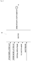
- FIG. 5 is a view illustrating an exemplary embodiment of a neural network model of the identifier of the apparatus for controlling the EGR valve according to the exemplary embodiment of the present disclosure.
- the neural network model may use a multilayer perceptron algorithm including an input layer neuron, a hidden layer neuron, and an output layer neuron.
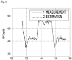
- the neural network model which completes learning, may simulate the output of the engine system 10 as it is, and this means that the engine system 10 is mathematically modeled.
- the learning of the neural network model is a process of comparing an engine system output y predicted by the neural network model with an actual engine system output y, and updating parameters of the neural network model so that the actual engine system output y becomes equal to the engine system output y predicted by the identifier 60. After the updating is completed, the neural network model shows the same behavior as the actual engine system 10.
- the learning of the neural network model may use a method widely known in the field of a back propagation learning algorithm.
- a learning pattern of the neural network model includes an input pattern and a target pattern.
- the target pattern means a value that needs to be outputted based on a particular input value when the particular input value is applied to the neural network model.
- signals are inputted to units of an input layer i, the signals are converted by the units and transmitted to a hidden layer j, and an output layer k finally outputs the signals.
- Connection strength between weights Wji and W1j is adjusted by decreasing a difference between the output value and an expected value while comparing the output value with the expected value, and then the process is performed again from the beginning. When this process is repeated, the error is decreased to an appropriate level, and the neural network model may simulate input and output behavior of the engine system 10.
- input variables which are inputted to the input layer i of the neural network model, may be inputted to the input layer i through a tapped delay line (TDL).
- TDL tapped delay line
- the input value which is to be inputted to the input layer i, has a vector form in which the current input variable value and the previous n input variable values are sequentially accumulated.
- the past values, as well as the current values may be applied to the neural network model, and as a result, learning accuracy of the neural network model may be improved.
- the neural network model may simulate the input and output behavior similar to the actual engine system 10 while iteratively performing the learning. Therefore, it is necessary to perform iterative learning in order to improve precision in the simulation of the neural network model.
- the neural network model may perform the learning by using data corresponding to various operation conditions in order to have a simulation ability with high accuracy with respect to various operation conditions that may occur in the engine system 10.
- the present exemplary embodiment describes that the identifier 60 is implemented by the neural network model, but the identifier 60 is not limited thereto, and the identifier 60 may be a black box model using various publicly known methods that may simulate the behavior of the engine system 10.
- the control calculation unit 40 compares the target amount r of fresh air with the current amount y of fresh air, and outputs a control signal for controlling the opening degree of the EGR valve 18 so that the current amount y of fresh air follows the target amount r of fresh air.
- the control calculation unit 40 may be a proportional-integral (PI) controller, but the control calculation unit 40 is not limited thereto, and the control calculation unit 40 may be various types of currently known controllers such as a proportional-integral-derivative (PID) controller. In the present exemplary embodiment, the description will be made assuming that the control calculation unit 40 is the PI controller.
- the control error e which is a difference between the target amount r of fresh air and the current amount y of fresh air
- the control calculation unit 40 receives the control error e and outputs the opening degree u of the EGR valve.
- a general PI controller which does not consider the identifier 60, calculates a proportional term based on the control error e and a proportional gain k p , calculates an integral term based on the control error e and an integral gain ki, and outputs the opening degree u of the EGR valve which is an output value
- the proportional gain k p , the control error e, the integral gain ki, and the opening degree u have the following relationship.
- the control calculation unit 40 may express the following expression in consideration of the engine system input-output sensitivity ⁇ y/ ⁇ u inputted to the control calculation unit 40 from the identifier 60 in the above expression.
- u k p ⁇ e + k i ⁇ ⁇ edt ⁇ y ⁇ u
- At least one gain which is utilized for the calculation of the control calculation unit 40, is divided by the engine system input-output sensitivity ⁇ y/ ⁇ u outputted from the identifier 60, thereby obtaining an effect in that the gain of the control calculation unit 40 is automatically corrected in accordance with a current driving state of the engine system 10.
- the gain of the control calculation unit 40 is decreased or a variation in gain is decreased.
- the proportional gain k p and the integral gain ki may be set through a gain setting unit 80, and the proportional gain k p and the integral gain ki may be changed to correspond to various operation conditions with reference to the preset lookup table.
- the lookup table which is simpler than that in the related art, may be used, such that the lookup table may be simply established.
- the control calculation unit 40 calculates operands such as a proportional term, an integral term, and a derivative term, and divides at least one of the proportional gain k p , the integral gain ki, and the differential gain kd, which are used for the operands, by the engine system input-output sensitivity ⁇ y/ ⁇ u.
- the control calculation unit 40 and the identifier 60 may be the same constituent element as the fresh air amount setting unit 30, the control calculation unit 40 and the identifier 60 may be formed as a part of the fresh air amount setting unit 30, or the control calculation unit 40 and the identifier 60 may be formed as independent constituent elements separately from the fresh air amount setting unit 30.
- the fresh air amount setting unit 30, the control calculation unit 40, and the identifier 60 may be parts of an electronic control unit (ECU) of the vehicle.
- ECU electronice control unit
- FIG. 9 is a flowchart of a method of controlling an EGR valve according to another exemplary embodiment of the present disclosure.
- the method of controlling the EGR valve according to the exemplary embodiment of the present disclosure includes measuring an operation condition of the engine system 10 and the current amount y of fresh air (S10), setting the target amount r of fresh air based on the operation condition (S22), calculating engine system input-output sensitivity ⁇ y/ ⁇ u based on the operation condition (S24), calculating the control error e by comparing the target amount of fresh air with the current amount of fresh air (S30), dividing a gain of the control calculation unit 40 by the engine system input-output sensitivity ⁇ y/ ⁇ u (S40), determining the opening degree u of the EGR valve so that the current amount y of fresh air follows the target amount r of fresh air (S50), and controlling the EGR valve 18 (S60).
- operation condition information of the engine system 10 is measured by the measurement unit, and the current amount y of fresh air is measured by the fresh air amount sensor 22.
- the measurement unit may include the engine rotational speed sensor 24 which measures the rotational speed of the engine, the fuel injection amount sensor 26 which measures the fuel injection amount, and the boost pressure sensor 28 which measures the boost pressure, and the measurement unit may include publicly known sensors for measuring various operation conditions of the engine.
- the measured operation conditions are outputted to the fresh air amount setting unit 30 and the identifier 60, and the current amount y of fresh air is outputted to the subtractor 70.
- the fresh air amount setting unit 30 may set the target amount r of fresh air by inputting the operation condition into the lookup table. Alternatively, the fresh air amount setting unit 30 may set the target amount r of fresh air by inputting the operation condition to a preset mathematical model. The set target amount r of fresh air is outputted to the subtractor 70.
- the identifier 60 calculates the engine system input-output sensitivity ⁇ y/ ⁇ u by receiving the opening degree u of the EGR valve, the current amount y of fresh air, and other operation conditions, and outputs the engine system input-output sensitivity ⁇ y/ ⁇ u to the control calculation unit 40.
- the subtractor 70 calculates the control error e by comparing the inputted target amount r of fresh air with the current amount y of fresh air.
- the calculated control error e is outputted to the control calculation unit 40.
- the control calculation unit 40 calculates the opening degree u of the EGR valve by receiving the control error e, and outputs the opening degree u of the EGR valve. Thereafter, the EGR valve 18 is controlled by a control signal related to the opening degree u of the EGR valve, which is outputted from the control calculation unit 40 (S60).
Landscapes
- Engineering & Computer Science (AREA)
- Chemical & Material Sciences (AREA)
- Combustion & Propulsion (AREA)
- Mechanical Engineering (AREA)
- General Engineering & Computer Science (AREA)
- Analytical Chemistry (AREA)
- Artificial Intelligence (AREA)
- Evolutionary Computation (AREA)
- Output Control And Ontrol Of Special Type Engine (AREA)
- Combined Controls Of Internal Combustion Engines (AREA)
Claims (12)
- Vorrichtung zum Steuern eines AGR-Ventils (16), wobei die Vorrichtung umfasst:eine Messeinheit, die dafür eingerichtet ist, mindestens eine Betriebsbedingung eines Motorsystems (10) zu messen;eine Frischluftmengen-Einstelleinheit (30), die dafür eingerichtet ist, eine Sollmenge an Frischluft auf der Grundlage der Betriebsbedingung einzustellen;einen Frischluftmengensensor (22), der dafür eingerichtet ist, eine momentane Frischluftmenge zu messen, die durch eine Ansaugleitung (12) eingeleitet wird;einen Identifizierer (60), der eingerichtet ist zum:Simulieren einer Eingabe und einer Ausgabe des Motorsystems (10), undAusgeben einer Eingabe-Ausgabe-Empfindlichkeit des Motorsystems (10), die ein Verhältnis einer Änderungsrate der momentanen Frischluftmenge zu einer Änderungsrate des Öffnungsgrades des AGR-Ventils (16) ist;eine Verstärkungseinstelleinheit (80), die dafür eingerichtet ist, mindestens eine Verstärkung gemäß einer Betriebsbedingung des Motorsystems (10) einzustellen; undeine Steuerungsberechnungseinheit (40), die eingerichtet ist zum:Korrigieren der Verstärkung gemäß der Betriebsbedingung des Motorsystems (10) durch Dividieren der Verstärkung durch die Eingabe-Ausgabe-Empfindlichkeit des Motorsystems (10),Vergleichen der Soll-Frischluftmenge mit der momentanen Frischluftmenge, um einen Steuerungsfehler (e) zu berechnen, undVerwenden der korrigierten Verstärkung und des berechneten Steuerungsfehlers (e) für ihre Berechnungen, um ein Steuersignal zum Steuern des Öffnungsgrades des AGR-Ventils (16) auszugeben, so dass die momentane Frischluftmenge der Soll-Frischluftmenge folgt.
- Vorrichtung nach Anspruch 1, wobei die Betriebsbedingung mindestens eines von einer Drehzahl eines Motors, einer Kraftstoffeinspritzmenge und einem Ladedruck umfasst, die sich auf eine Änderung der Frischluftmenge auswirken, und wobei die Betriebsbedingung in den Identifizierer (60) eingegeben wird.
- Vorrichtung nach Anspruch 1, wobei der Identifizierer (60) ein Neuronennetzmodell ist.
- Vorrichtung nach Anspruch 3, wobei das Neuronennetzmodell ein Eingabeschicht-Neuron, ein Verborgene-Schicht-Neuron und ein Ausgabeschicht-Neuron umfasst und die Betriebsbedingung über eine abgegriffene Verzögerungsleitung (Tapped Delay Line, TDL) in das Eingabeschicht-Neuron eingegeben wird, wobei das Lernen des Neuronennetzmodells das Vorhersagen der Ausgabe des Motorsystems (10), das Vergleichen der vorhergesagten Ausgabe mit der tatsächlichen Ausgabe des Motorsystems (10), und das Aktualisieren von Parametern des neuronalen Netzes umfasst, so dass die Ausgabe des Motorsystems (10) gleich der vorhergesagten Ausgabe des Motorsystems (10) wird.
- Vorrichtung nach Anspruch 1, wobei die Soll-Frischluftmenge durch Eingeben der Betriebsbedingung in eine Nachschlagetabelle erhalten wird.
- Vorrichtung nach Anspruch 1, des Weiteren umfassend:
einen Subtrahierer (70), der eingerichtet ist zum:
Berechnen eines Steuerungsfehlers durch Vergleichen der Soll-Frischluftmenge mit der momentanen Frischluftmenge und Ausgeben des Steuerungsfehlers an die Steuerungsberechnungseinheit. - Vorrichtung nach Anspruch 1, wobei die Verstärkung eine proportionale Verstärkung und eine integrale Verstärkung umfasst.
- Verfahren zum Steuern eines AGR-Ventils (16), wobei das Verfahren umfasst:Messen einer Betriebsbedingung eines Motorsystems (10) und einer momentanen Frischluftmenge, die durch eine Ansaugleitung (12) eingeleitet wird;Einstellen einer Soll-Frischluftmenge auf der Grundlage der Betriebsbedingung;Berechnen, auf der Grundlage der Betriebsbedingung, der Eingabe-Ausgabe-Empfindlichkeit des Motorsystems (10), die ein Verhältnis einer Änderungsrate der momentanen Frischluftmenge zu einer Änderungsrate eines Öffnungsgrades des AGR-Ventils (16) ist, wobei das Berechnen der Eingabe-Ausgabe-Empfindlichkeit des Motorsystems (10) das Simulieren einer Eingabe und einer Ausgabe des Motorsystems (10) umfasst;Berechnen eines Steuerungsfehlers (e) durch Vergleichen der Soll-Frischluftmenge mit der momentanen Frischluftmenge;Einstellen mindestens einer Verstärkung gemäß einer Betriebsbedingung des Motorsystems (10);Korrigieren der Verstärkung gemäß der Betriebsbedingung eines Motorsystems (10) durch Dividieren der Verstärkung durch die Eingabe-Ausgabe-Empfindlichkeit des Motorsystems (10) ;Verwenden der korrigierten Verstärkung und des berechneten Steuerungsfehlers (e) zum Steuern des Öffnungsgrades des AGR-Ventils (16), so dass die momentane Frischluftmenge der Soll-Frischluftmenge folgt.
- Verfahren nach Anspruch 8, wobei die Betriebsbedingung mindestens eines von einer Drehzahl eines Motors, einer Kraftstoffeinspritzmenge und dem Ladedruck umfasst.
- Verfahren nach Anspruch 8, wobei das Einstellen der Soll-Frischluftmenge das Erhalten der Soll-Frischluftmenge durch Eingeben der Betriebsbedingung in eine Nachschlagetabelle umfasst.
- Verfahren nach Anspruch 8, wobei die Eingabe-Ausgabe-Empfindlichkeit des Motorsystems (10) durch einen Identifizierer berechnet wird, der ein Neuronennetzmodell verwendet.
- Verfahren nach Anspruch 11, wobei das Neuronennetzmodell ein Eingabeschicht-Neuron, ein Verborgene-Schicht-Neuron und ein Ausgabeschicht-Neuron umfasst und die Betriebsbedingung über eine abgegriffene Verzögerungsleitung (Tapped Delay Line, TDL) in das Eingabeschicht-Neuron eingegeben wird.
Applications Claiming Priority (2)
| Application Number | Priority Date | Filing Date | Title |
|---|---|---|---|
| KR1020150002720A KR102216860B1 (ko) | 2015-01-08 | 2015-01-08 | Egr 밸브 제어 장치 및 제어 방법 |
| PCT/KR2016/000186 WO2016111581A1 (ko) | 2015-01-08 | 2016-01-08 | Egr 밸브 제어 장치 및 제어 방법 |
Publications (3)
| Publication Number | Publication Date |
|---|---|
| EP3244043A1 EP3244043A1 (de) | 2017-11-15 |
| EP3244043A4 EP3244043A4 (de) | 2018-12-12 |
| EP3244043B1 true EP3244043B1 (de) | 2021-09-01 |
Family
ID=56356193
Family Applications (1)
| Application Number | Title | Priority Date | Filing Date |
|---|---|---|---|
| EP16735202.0A Not-in-force EP3244043B1 (de) | 2015-01-08 | 2016-01-08 | Vorrichtung und verfahren zur steuerung eines agr-ventils |
Country Status (4)
| Country | Link |
|---|---|
| US (1) | US10337428B2 (de) |
| EP (1) | EP3244043B1 (de) |
| KR (1) | KR102216860B1 (de) |
| WO (1) | WO2016111581A1 (de) |
Families Citing this family (5)
| Publication number | Priority date | Publication date | Assignee | Title |
|---|---|---|---|---|
| CN106121840A (zh) * | 2016-08-23 | 2016-11-16 | 无锡隆盛科技股份有限公司 | 智能egr阀 |
| CN109799699B (zh) * | 2019-02-19 | 2022-06-07 | 阿波罗智能技术(北京)有限公司 | 自动驾驶系统控制参数处理方法、装置、设备、存储介质 |
| KR102121393B1 (ko) * | 2019-03-18 | 2020-06-10 | 군산대학교 산학협력단 | 위치 제어 방법 및 위치 제어기 |
| WO2021173196A1 (en) * | 2020-02-24 | 2021-09-02 | Tula Technology, Inc. | Diagnostic system and method for detecting internal combustion engine faults using exhaust pressure readings |
| CN114233486B (zh) * | 2021-11-12 | 2023-08-18 | 潍柴动力股份有限公司 | 一种egr阀的控制方法、装置及ecu |
Family Cites Families (15)
| Publication number | Priority date | Publication date | Assignee | Title |
|---|---|---|---|---|
| JPS62233465A (ja) * | 1986-04-01 | 1987-10-13 | Mitsubishi Motors Corp | 内燃機関のegr率制御方法 |
| JPH04365947A (ja) * | 1991-06-11 | 1992-12-17 | Nippondenso Co Ltd | エンジン用空燃比制御装置 |
| US5377651A (en) * | 1993-12-27 | 1995-01-03 | General Motors Corporation | Closed-loop control of a diesel engine |
| DE19603472C2 (de) * | 1996-01-31 | 2001-10-25 | Siemens Ag | Verfahren zur Steuerung einer Abgasrückführvorrichtung einer Brennkraftmaschine |
| JPH1136962A (ja) * | 1997-07-18 | 1999-02-09 | Toyota Motor Corp | ディーゼルエンジンの燃料噴射量制御装置 |
| EP2098715A4 (de) | 2006-12-28 | 2018-01-03 | Mitsubishi Electric Corporation | Agr-ventilsteuervorrichtung |
| GB2463018A (en) * | 2008-08-28 | 2010-03-03 | Gm Global Tech Operations Inc | Method for controlling the EGR and Throttle Valves in an IC E ngine |
| KR101091634B1 (ko) * | 2009-12-04 | 2011-12-08 | 현대자동차주식회사 | 디젤엔진의 저압 이지알 제어방법 |
| JP5229402B2 (ja) * | 2009-12-21 | 2013-07-03 | 富士通株式会社 | エンジン制御プログラム、方法及び装置 |
| CA2692168A1 (en) * | 2010-02-23 | 2011-08-23 | Leonardo E. Alvarino | Folding trailer |
| KR20110138919A (ko) * | 2010-06-22 | 2011-12-28 | 현대자동차주식회사 | 배기가스 재순환 밸브 제어 방법 |
| KR20130043288A (ko) * | 2011-10-20 | 2013-04-30 | 한양대학교 산학협력단 | 엔진 배기가스 재순환 제어시스템 및 제어방법 |
| US9702308B2 (en) * | 2012-04-25 | 2017-07-11 | Komatsu Ltd. | Diesel engine and method for controlling diesel engine |
| US9228511B2 (en) * | 2012-10-19 | 2016-01-05 | Cummins Inc. | Engine feedback control system and method |
| US9790877B2 (en) * | 2012-12-26 | 2017-10-17 | Doosan Infracore Co., Ltd. | Method and apparatus for controlling EGR |
-
2015
- 2015-01-08 KR KR1020150002720A patent/KR102216860B1/ko not_active Expired - Fee Related
-
2016
- 2016-01-08 EP EP16735202.0A patent/EP3244043B1/de not_active Not-in-force
- 2016-01-08 WO PCT/KR2016/000186 patent/WO2016111581A1/ko not_active Ceased
-
2017
- 2017-07-10 US US15/645,156 patent/US10337428B2/en not_active Expired - Fee Related
Also Published As
| Publication number | Publication date |
|---|---|
| KR102216860B1 (ko) | 2021-02-18 |
| EP3244043A4 (de) | 2018-12-12 |
| WO2016111581A1 (ko) | 2016-07-14 |
| KR20160085563A (ko) | 2016-07-18 |
| US10337428B2 (en) | 2019-07-02 |
| EP3244043A1 (de) | 2017-11-15 |
| US20170306870A1 (en) | 2017-10-26 |
Similar Documents
| Publication | Publication Date | Title |
|---|---|---|
| US11506138B2 (en) | Engine system with inferential sensor | |
| EP3244043B1 (de) | Vorrichtung und verfahren zur steuerung eines agr-ventils | |
| US7831371B2 (en) | Control apparatus for an internal combustion engine | |
| US6862514B2 (en) | Model generating method, model generating program, and simulation apparatus | |
| KR101974654B1 (ko) | 내연기관을 구비한 엔진 시스템에서 물리적 변수를 위한 모델링 값을 결정하는 방법 및 그 장치 | |
| EP2735486A1 (de) | Multivariables Steuersystem | |
| KR102596784B1 (ko) | 내연 기관을 갖는 엔진 시스템의 배기가스 후처리 장치를 작동시키기 위한 방법 및 장치 | |
| US20200378330A1 (en) | Abnormality detection system of exhaust gas recirculation system | |
| US9086025B2 (en) | Systems and methods for correcting mass airflow sensor drift | |
| CN113728159B (zh) | 发动机控制系统 | |
| CN113417776B (zh) | 一种流量测量方法及控制器 | |
| US20070233326A1 (en) | Engine self-tuning methods and systems | |
| Iwadare et al. | Multi-variable air-path management for a clean diesel engine using model predictive control | |
| CN101509433A (zh) | 基于Lambda闭环控制的氧传感器劣化模拟器控制偏差的校准方法 | |
| JP2013144975A (ja) | 推論検知のモデルベース較正 | |
| US20190153969A1 (en) | System and method for emissions determination and correction | |
| US20210054793A1 (en) | Method for determining the cylinder air-charge of an internal combustion engine in a non-fired operation | |
| EP3464859B1 (de) | Verfahren zur modellierung von afr zur kompensation für wraf-sensor | |
| Arsie et al. | Development and real-time implementation of recurrent neural networks for AFR prediction and control | |
| JP6234531B1 (ja) | 内燃機関制御装置 | |
| EP3112652B1 (de) | Agr-steuerungsverfahren und agr-vorrichtung | |
| KR20120103642A (ko) | 배기가스 재순환 방법 | |
| JP2007265212A (ja) | プラントの制御装置及びプラントの制御方法 | |
| Arsie et al. | Experimental validation of a neural network based A/F virtual sensor for SI engine control | |
| US10648421B2 (en) | System and method for controlling fuel injection in flex-fuel vehicle |
Legal Events
| Date | Code | Title | Description |
|---|---|---|---|
| STAA | Information on the status of an ep patent application or granted ep patent |
Free format text: STATUS: THE INTERNATIONAL PUBLICATION HAS BEEN MADE |
|
| PUAI | Public reference made under article 153(3) epc to a published international application that has entered the european phase |
Free format text: ORIGINAL CODE: 0009012 |
|
| STAA | Information on the status of an ep patent application or granted ep patent |
Free format text: STATUS: REQUEST FOR EXAMINATION WAS MADE |
|
| 17P | Request for examination filed |
Effective date: 20170803 |
|
| AK | Designated contracting states |
Kind code of ref document: A1 Designated state(s): AL AT BE BG CH CY CZ DE DK EE ES FI FR GB GR HR HU IE IS IT LI LT LU LV MC MK MT NL NO PL PT RO RS SE SI SK SM TR |
|
| AX | Request for extension of the european patent |
Extension state: BA ME |
|
| RIN1 | Information on inventor provided before grant (corrected) |
Inventor name: KIM, DUK SANG Inventor name: OH, BYOUNG GUL |
|
| DAV | Request for validation of the european patent (deleted) | ||
| DAX | Request for extension of the european patent (deleted) | ||
| REG | Reference to a national code |
Ref country code: DE Ref legal event code: R079 Ref document number: 602016063068 Country of ref document: DE Free format text: PREVIOUS MAIN CLASS: F02D0021080000 Ipc: F02D0033020000 |
|
| A4 | Supplementary search report drawn up and despatched |
Effective date: 20181114 |
|
| RIC1 | Information provided on ipc code assigned before grant |
Ipc: F02M 26/52 20160101ALI20181108BHEP Ipc: F02D 21/08 20060101ALI20181108BHEP Ipc: F02D 33/02 20060101AFI20181108BHEP Ipc: F02D 41/18 20060101ALI20181108BHEP Ipc: F02D 41/14 20060101ALI20181108BHEP Ipc: F02M 26/46 20160101ALI20181108BHEP |
|
| STAA | Information on the status of an ep patent application or granted ep patent |
Free format text: STATUS: EXAMINATION IS IN PROGRESS |
|
| 17Q | First examination report despatched |
Effective date: 20201124 |
|
| GRAP | Despatch of communication of intention to grant a patent |
Free format text: ORIGINAL CODE: EPIDOSNIGR1 |
|
| STAA | Information on the status of an ep patent application or granted ep patent |
Free format text: STATUS: GRANT OF PATENT IS INTENDED |
|
| INTG | Intention to grant announced |
Effective date: 20210406 |
|
| GRAS | Grant fee paid |
Free format text: ORIGINAL CODE: EPIDOSNIGR3 |
|
| GRAA | (expected) grant |
Free format text: ORIGINAL CODE: 0009210 |
|
| STAA | Information on the status of an ep patent application or granted ep patent |
Free format text: STATUS: THE PATENT HAS BEEN GRANTED |
|
| AK | Designated contracting states |
Kind code of ref document: B1 Designated state(s): AL AT BE BG CH CY CZ DE DK EE ES FI FR GB GR HR HU IE IS IT LI LT LU LV MC MK MT NL NO PL PT RO RS SE SI SK SM TR |
|
| REG | Reference to a national code |
Ref country code: GB Ref legal event code: FG4D |
|
| REG | Reference to a national code |
Ref country code: CH Ref legal event code: EP Ref country code: AT Ref legal event code: REF Ref document number: 1426483 Country of ref document: AT Kind code of ref document: T Effective date: 20210915 |
|
| REG | Reference to a national code |
Ref country code: DE Ref legal event code: R096 Ref document number: 602016063068 Country of ref document: DE |
|
| REG | Reference to a national code |
Ref country code: IE Ref legal event code: FG4D |
|
| REG | Reference to a national code |
Ref country code: DE Ref legal event code: R081 Ref document number: 602016063068 Country of ref document: DE Owner name: HYUNDAI DOOSAN INFRACORE CO., LTD., KR Free format text: FORMER OWNER: DOOSAN INFRACORE CO., LTD., INCHEON, KR |
|
| RAP4 | Party data changed (patent owner data changed or rights of a patent transferred) |
Owner name: HYUNDAI DOOSAN INFRACORE CO., LTD. |
|
| REG | Reference to a national code |
Ref country code: LT Ref legal event code: MG9D |
|
| REG | Reference to a national code |
Ref country code: NL Ref legal event code: MP Effective date: 20210901 |
|
| PG25 | Lapsed in a contracting state [announced via postgrant information from national office to epo] |
Ref country code: LT Free format text: LAPSE BECAUSE OF FAILURE TO SUBMIT A TRANSLATION OF THE DESCRIPTION OR TO PAY THE FEE WITHIN THE PRESCRIBED TIME-LIMIT Effective date: 20210901 Ref country code: BG Free format text: LAPSE BECAUSE OF FAILURE TO SUBMIT A TRANSLATION OF THE DESCRIPTION OR TO PAY THE FEE WITHIN THE PRESCRIBED TIME-LIMIT Effective date: 20211201 Ref country code: NO Free format text: LAPSE BECAUSE OF FAILURE TO SUBMIT A TRANSLATION OF THE DESCRIPTION OR TO PAY THE FEE WITHIN THE PRESCRIBED TIME-LIMIT Effective date: 20211201 Ref country code: ES Free format text: LAPSE BECAUSE OF FAILURE TO SUBMIT A TRANSLATION OF THE DESCRIPTION OR TO PAY THE FEE WITHIN THE PRESCRIBED TIME-LIMIT Effective date: 20210901 Ref country code: FI Free format text: LAPSE BECAUSE OF FAILURE TO SUBMIT A TRANSLATION OF THE DESCRIPTION OR TO PAY THE FEE WITHIN THE PRESCRIBED TIME-LIMIT Effective date: 20210901 Ref country code: HR Free format text: LAPSE BECAUSE OF FAILURE TO SUBMIT A TRANSLATION OF THE DESCRIPTION OR TO PAY THE FEE WITHIN THE PRESCRIBED TIME-LIMIT Effective date: 20210901 Ref country code: RS Free format text: LAPSE BECAUSE OF FAILURE TO SUBMIT A TRANSLATION OF THE DESCRIPTION OR TO PAY THE FEE WITHIN THE PRESCRIBED TIME-LIMIT Effective date: 20210901 Ref country code: SE Free format text: LAPSE BECAUSE OF FAILURE TO SUBMIT A TRANSLATION OF THE DESCRIPTION OR TO PAY THE FEE WITHIN THE PRESCRIBED TIME-LIMIT Effective date: 20210901 |
|
| REG | Reference to a national code |
Ref country code: AT Ref legal event code: MK05 Ref document number: 1426483 Country of ref document: AT Kind code of ref document: T Effective date: 20210901 |
|
| PG25 | Lapsed in a contracting state [announced via postgrant information from national office to epo] |
Ref country code: PL Free format text: LAPSE BECAUSE OF FAILURE TO SUBMIT A TRANSLATION OF THE DESCRIPTION OR TO PAY THE FEE WITHIN THE PRESCRIBED TIME-LIMIT Effective date: 20210901 Ref country code: LV Free format text: LAPSE BECAUSE OF FAILURE TO SUBMIT A TRANSLATION OF THE DESCRIPTION OR TO PAY THE FEE WITHIN THE PRESCRIBED TIME-LIMIT Effective date: 20210901 Ref country code: GR Free format text: LAPSE BECAUSE OF FAILURE TO SUBMIT A TRANSLATION OF THE DESCRIPTION OR TO PAY THE FEE WITHIN THE PRESCRIBED TIME-LIMIT Effective date: 20211202 |
|
| PG25 | Lapsed in a contracting state [announced via postgrant information from national office to epo] |
Ref country code: AT Free format text: LAPSE BECAUSE OF FAILURE TO SUBMIT A TRANSLATION OF THE DESCRIPTION OR TO PAY THE FEE WITHIN THE PRESCRIBED TIME-LIMIT Effective date: 20210901 |
|
| PGFP | Annual fee paid to national office [announced via postgrant information from national office to epo] |
Ref country code: DE Payment date: 20211214 Year of fee payment: 7 |
|
| PG25 | Lapsed in a contracting state [announced via postgrant information from national office to epo] |
Ref country code: IS Free format text: LAPSE BECAUSE OF FAILURE TO SUBMIT A TRANSLATION OF THE DESCRIPTION OR TO PAY THE FEE WITHIN THE PRESCRIBED TIME-LIMIT Effective date: 20220101 Ref country code: SM Free format text: LAPSE BECAUSE OF FAILURE TO SUBMIT A TRANSLATION OF THE DESCRIPTION OR TO PAY THE FEE WITHIN THE PRESCRIBED TIME-LIMIT Effective date: 20210901 Ref country code: SK Free format text: LAPSE BECAUSE OF FAILURE TO SUBMIT A TRANSLATION OF THE DESCRIPTION OR TO PAY THE FEE WITHIN THE PRESCRIBED TIME-LIMIT Effective date: 20210901 Ref country code: RO Free format text: LAPSE BECAUSE OF FAILURE TO SUBMIT A TRANSLATION OF THE DESCRIPTION OR TO PAY THE FEE WITHIN THE PRESCRIBED TIME-LIMIT Effective date: 20210901 Ref country code: PT Free format text: LAPSE BECAUSE OF FAILURE TO SUBMIT A TRANSLATION OF THE DESCRIPTION OR TO PAY THE FEE WITHIN THE PRESCRIBED TIME-LIMIT Effective date: 20220103 Ref country code: NL Free format text: LAPSE BECAUSE OF FAILURE TO SUBMIT A TRANSLATION OF THE DESCRIPTION OR TO PAY THE FEE WITHIN THE PRESCRIBED TIME-LIMIT Effective date: 20210901 Ref country code: EE Free format text: LAPSE BECAUSE OF FAILURE TO SUBMIT A TRANSLATION OF THE DESCRIPTION OR TO PAY THE FEE WITHIN THE PRESCRIBED TIME-LIMIT Effective date: 20210901 Ref country code: CZ Free format text: LAPSE BECAUSE OF FAILURE TO SUBMIT A TRANSLATION OF THE DESCRIPTION OR TO PAY THE FEE WITHIN THE PRESCRIBED TIME-LIMIT Effective date: 20210901 Ref country code: AL Free format text: LAPSE BECAUSE OF FAILURE TO SUBMIT A TRANSLATION OF THE DESCRIPTION OR TO PAY THE FEE WITHIN THE PRESCRIBED TIME-LIMIT Effective date: 20210901 |
|
| REG | Reference to a national code |
Ref country code: DE Ref legal event code: R097 Ref document number: 602016063068 Country of ref document: DE |
|
| PLBE | No opposition filed within time limit |
Free format text: ORIGINAL CODE: 0009261 |
|
| STAA | Information on the status of an ep patent application or granted ep patent |
Free format text: STATUS: NO OPPOSITION FILED WITHIN TIME LIMIT |
|
| PG25 | Lapsed in a contracting state [announced via postgrant information from national office to epo] |
Ref country code: IT Free format text: LAPSE BECAUSE OF FAILURE TO SUBMIT A TRANSLATION OF THE DESCRIPTION OR TO PAY THE FEE WITHIN THE PRESCRIBED TIME-LIMIT Effective date: 20210901 Ref country code: DK Free format text: LAPSE BECAUSE OF FAILURE TO SUBMIT A TRANSLATION OF THE DESCRIPTION OR TO PAY THE FEE WITHIN THE PRESCRIBED TIME-LIMIT Effective date: 20210901 |
|
| 26N | No opposition filed |
Effective date: 20220602 |
|
| PG25 | Lapsed in a contracting state [announced via postgrant information from national office to epo] |
Ref country code: SI Free format text: LAPSE BECAUSE OF FAILURE TO SUBMIT A TRANSLATION OF THE DESCRIPTION OR TO PAY THE FEE WITHIN THE PRESCRIBED TIME-LIMIT Effective date: 20210901 Ref country code: MC Free format text: LAPSE BECAUSE OF FAILURE TO SUBMIT A TRANSLATION OF THE DESCRIPTION OR TO PAY THE FEE WITHIN THE PRESCRIBED TIME-LIMIT Effective date: 20210901 |
|
| REG | Reference to a national code |
Ref country code: CH Ref legal event code: PL |
|
| GBPC | Gb: european patent ceased through non-payment of renewal fee |
Effective date: 20220108 |
|
| REG | Reference to a national code |
Ref country code: BE Ref legal event code: MM Effective date: 20220131 |
|
| PG25 | Lapsed in a contracting state [announced via postgrant information from national office to epo] |
Ref country code: LU Free format text: LAPSE BECAUSE OF NON-PAYMENT OF DUE FEES Effective date: 20220108 Ref country code: GB Free format text: LAPSE BECAUSE OF NON-PAYMENT OF DUE FEES Effective date: 20220108 |
|
| PG25 | Lapsed in a contracting state [announced via postgrant information from national office to epo] |
Ref country code: FR Free format text: LAPSE BECAUSE OF NON-PAYMENT OF DUE FEES Effective date: 20220131 Ref country code: BE Free format text: LAPSE BECAUSE OF NON-PAYMENT OF DUE FEES Effective date: 20220131 |
|
| PG25 | Lapsed in a contracting state [announced via postgrant information from national office to epo] |
Ref country code: LI Free format text: LAPSE BECAUSE OF NON-PAYMENT OF DUE FEES Effective date: 20220131 Ref country code: CH Free format text: LAPSE BECAUSE OF NON-PAYMENT OF DUE FEES Effective date: 20220131 |
|
| PG25 | Lapsed in a contracting state [announced via postgrant information from national office to epo] |
Ref country code: IE Free format text: LAPSE BECAUSE OF NON-PAYMENT OF DUE FEES Effective date: 20220108 |
|
| REG | Reference to a national code |
Ref country code: DE Ref legal event code: R119 Ref document number: 602016063068 Country of ref document: DE |
|
| PG25 | Lapsed in a contracting state [announced via postgrant information from national office to epo] |
Ref country code: DE Free format text: LAPSE BECAUSE OF NON-PAYMENT OF DUE FEES Effective date: 20230801 |
|
| PG25 | Lapsed in a contracting state [announced via postgrant information from national office to epo] |
Ref country code: HU Free format text: LAPSE BECAUSE OF FAILURE TO SUBMIT A TRANSLATION OF THE DESCRIPTION OR TO PAY THE FEE WITHIN THE PRESCRIBED TIME-LIMIT; INVALID AB INITIO Effective date: 20160108 |
|
| PG25 | Lapsed in a contracting state [announced via postgrant information from national office to epo] |
Ref country code: MK Free format text: LAPSE BECAUSE OF FAILURE TO SUBMIT A TRANSLATION OF THE DESCRIPTION OR TO PAY THE FEE WITHIN THE PRESCRIBED TIME-LIMIT Effective date: 20210901 Ref country code: CY Free format text: LAPSE BECAUSE OF FAILURE TO SUBMIT A TRANSLATION OF THE DESCRIPTION OR TO PAY THE FEE WITHIN THE PRESCRIBED TIME-LIMIT Effective date: 20210901 |
|
| PG25 | Lapsed in a contracting state [announced via postgrant information from national office to epo] |
Ref country code: MT Free format text: LAPSE BECAUSE OF FAILURE TO SUBMIT A TRANSLATION OF THE DESCRIPTION OR TO PAY THE FEE WITHIN THE PRESCRIBED TIME-LIMIT Effective date: 20210901 |
|
| PG25 | Lapsed in a contracting state [announced via postgrant information from national office to epo] |
Ref country code: TR Free format text: LAPSE BECAUSE OF FAILURE TO SUBMIT A TRANSLATION OF THE DESCRIPTION OR TO PAY THE FEE WITHIN THE PRESCRIBED TIME-LIMIT Effective date: 20210901 |