EP3244073B1 - Dispositif de fixation sur un composant - Google Patents
Dispositif de fixation sur un composant Download PDFInfo
- Publication number
- EP3244073B1 EP3244073B1 EP17163324.1A EP17163324A EP3244073B1 EP 3244073 B1 EP3244073 B1 EP 3244073B1 EP 17163324 A EP17163324 A EP 17163324A EP 3244073 B1 EP3244073 B1 EP 3244073B1
- Authority
- EP
- European Patent Office
- Prior art keywords
- sleeve
- screw
- abutment
- thread
- prevention means
- Prior art date
- Legal status (The legal status is an assumption and is not a legal conclusion. Google has not performed a legal analysis and makes no representation as to the accuracy of the status listed.)
- Active
Links
Images



Classifications
-
- F—MECHANICAL ENGINEERING; LIGHTING; HEATING; WEAPONS; BLASTING
- F16—ENGINEERING ELEMENTS AND UNITS; GENERAL MEASURES FOR PRODUCING AND MAINTAINING EFFECTIVE FUNCTIONING OF MACHINES OR INSTALLATIONS; THERMAL INSULATION IN GENERAL
- F16B—DEVICES FOR FASTENING OR SECURING CONSTRUCTIONAL ELEMENTS OR MACHINE PARTS TOGETHER, e.g. NAILS, BOLTS, CIRCLIPS, CLAMPS, CLIPS OR WEDGES; JOINTS OR JOINTING
- F16B5/00—Joining sheets or plates, e.g. panels, to one another or to strips or bars parallel to them
- F16B5/02—Joining sheets or plates, e.g. panels, to one another or to strips or bars parallel to them by means of fastening members using screw-thread
- F16B5/0216—Joining sheets or plates, e.g. panels, to one another or to strips or bars parallel to them by means of fastening members using screw-thread the position of the plates to be connected being adjustable
- F16B5/0233—Joining sheets or plates, e.g. panels, to one another or to strips or bars parallel to them by means of fastening members using screw-thread the position of the plates to be connected being adjustable allowing for adjustment perpendicular to the plane of the plates
-
- F—MECHANICAL ENGINEERING; LIGHTING; HEATING; WEAPONS; BLASTING
- F16—ENGINEERING ELEMENTS AND UNITS; GENERAL MEASURES FOR PRODUCING AND MAINTAINING EFFECTIVE FUNCTIONING OF MACHINES OR INSTALLATIONS; THERMAL INSULATION IN GENERAL
- F16B—DEVICES FOR FASTENING OR SECURING CONSTRUCTIONAL ELEMENTS OR MACHINE PARTS TOGETHER, e.g. NAILS, BOLTS, CIRCLIPS, CLAMPS, CLIPS OR WEDGES; JOINTS OR JOINTING
- F16B41/00—Measures against loss of bolts, nuts, or pins; Measures against unauthorised operation of bolts, nuts or pins
- F16B41/002—Measures against loss of bolts, nuts or pins
Definitions
- the present invention relates to a device for fixing to a component, in particular tolerance compensation element, with a first sleeve and a second sleeve attachable to and / or in the first sleeve by means of a screw connection, wherein the first sleeve and the second sleeve each have a Having passage, wherein a screw through the passages and preferably through the component into a thread of a holding means can be screwed, wherein the direction of rotation of the thread of the screw connection differs from the direction of rotation of the holding means and wherein on the second sleeve a driving device is formed with the screw can interact.
- Corresponding devices are for example from the DE 10 2013 200 999 A1 .
- the present invention is therefore the object of a device of the type mentioned in such a way and further develop that with simple design means reliable fixation of the components with ease of use is possible.
- the above object is achieved by the features of claim 1.
- the device in question is characterized in that a releasable anti-rotation is arranged and that the first sleeve and the second sleeve are held by the anti-rotation in a defined, nested position.
- the anti-rotation device is designed such that the first sleeve and the second sleeve in a predetermined position in which the sleeves are screwed into each other, are held. This ensures that the sleeves always have the same distance from each other, so that installation of the devices with concrete predetermined steps is possible. A control and adjustment of the distance of the sleeves by turning in or out of the sleeves is not necessary. Since the rotation is releasable, it can release the rotational movement between the first sleeve and second sleeve before or through the insertion / screwing of the screw.
- the term "releasable" in relation to the rotation is to be understood in that the rotation - whatever - is defined overcome, so that a rotational movement of the sleeves against each other is possible. Consequently, the anti-rotation serves in particular as a transport safety, namely blocks a rotation of the sleeves against each other, so that the distance of the sleeve is fixed predetermined.
- the anti-rotation device can be realized by a break element that extends from the first sleeve into the passage. It can be formed on the second sleeve, preferably projecting into the passage, abutment, so that the break element abuts the sleeve during rotation of the sleeves and inhibits the rotational movement.
- the abutment can fork-shaped, in particular by two projections, be realized, wherein the projections receive the fracture element between them.
- the abutment may be formed by a correspondingly shaped blocking means, so that the blocking means fulfills a dual function, namely serves as part of the rotation and as part of the driving device.
- the breaking element has two elevations, in which engages the abutment. Thus, a rotational movement in both directions is suppressed.
- the fracture element insertion bevels may be formed so that the fracture element snaps into the abutment when rotating the sleeves over the elevations.
- a force applied to the fracture element and / or the abutment can be exerted by a screw introduced into the passages, wherein the fracture element and / or the abutment can break off upon reaching a defined force and thus releases the rotational movement between the two sleeves.
- the breaking element and / or the abutment has at least one predetermined breaking point.
- the force required to break the fracture element and / or the abutment can be adjusted by the choice of geometry and / or material and / or the number of break points of the fracture element and / or the abutment.
- the rotation is formed as a clip.
- the clip may be an integral part of one of the two sleeves.
- the clip may be formed integrally with one of the sleeves, for example, as an injection molded part and engage around the other sleeve and / or engage in this.
- the clip may be constructed such that it can be broken off from the sleeve of which it is a part, in order to thus solve the rotation.
- the clip is detachably connected to both the first sleeve and the second sleeve.
- the clip can encompass or engage in the first sleeve and / or the second sleeve.
- first sleeve and the second sleeve may be integrally connected to each other in order to realize the rotation.
- an adhesive can be used to produce the integral connection. This can be selected or adapted such that the connection is released or released when a defined torque or a defined There is force between the first sleeve and the second sleeve.
- the adhesive may be applied to axially opposed surfaces of the first sleeve and the second sleeve.
- the adhesive may be applied between the threads of the first sleeve and the second sleeve that realize the screw connection.
- the threads of the first and second sleeve, which realize the screw connection at least partially not correspond to each other, so that the rotation is realized via a threaded clamp.
- the two sleeves can be screwed together with a matched torque, so that the desired Thread clamping is achieved by which the rotation is realized.
- a contact surface of the first sleeve and a, in particular axially opposite, contact surface of the second sleeve are connected to each other at least partially non-positively.
- the contact surface of the first sleeve and / or the contact surface of the second sleeve made of an elastomer, in particular rubber, and / or have elevations or depressions.
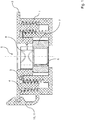
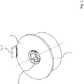
- the bracket 12 has a first leg 13 which engages in the first sleeve 1. Furthermore, a second leg 14 is formed, with which the clip surrounds the second sleeve 2, so that an anti-twist device 11 is realized. To release the anti-rotation 11, the clip 12 can be removed, for example by hand from the device.
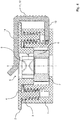
- FIGS. 6 and 7 show a further embodiment of a device according to the invention.
- the rotation 11 is realized by an adhesive which is applied in the first thread 3 and / or the second thread 4 of the first sleeve 1 and second sleeve 2.
- the adhesive is selected or tuned such that the two sleeves 1, 2 can be unscrewed when a defined torque acts on them.
- the torque is to be chosen so that the driving device 8 can transmit a correspondingly large torque from the screw to the second sleeve 2.
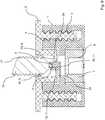
- FIG. 8 a further embodiment of a device according to the invention is shown in a schematic representation.
- the driving device 8 is realized by a protruding into the passage 5 threaded member 16 and extending into the passage blocking means 23 which is formed in the insertion direction of the screw after the threaded member 16.
- the threaded element 16 and the blocking means 23 are designed as nose or material collection.
- FIG. 8 Furthermore, serving as anti-rotation 11 break element 19 is shown, which extends from the first sleeve 1 in the passage 5 in.
- the blocking means 23 additionally serves as an abutment 20 for the break element 19.
- the blocking means 23 is fork-shaped, so that it is in both directions of rotation are locked. It is essential that the break element 19 seen in the insertion direction of the screw 18 protrudes in front of the blocking means 23, so that the screw 18 first comes into contact with the fracture element 19.
- the breaking element 19 is acted upon by the introduction or screwing in of the screw 18 with a force and breaks, in particular at the predetermined breaking point 22, when a defined force is exceeded. Once the break element 19 is broken away, the rotation 11 is released.
- the threaded member 16 serves as a mating thread for the thread 17 of the screw 18.
- the screw 18 When the screw 18 is inserted into the passage 5, it abuts against the threaded member 16, but can be moved by rotating in the axial direction. When the anti-rotation 11 is released or broken away, the screw 18 abuts the blocking means 23. By further screwing the screw 18, this is fixed between the threaded member 16 and blocking means 23 and is thus connected to the second sleeve 2. Due to the rotational movement of the screw 18, the second sleeve 2 from the first sleeve 1 can be unscrewed.
- the torque acting on the blocking means 23 or the force acting on the blocking means 23 increases as soon as the components 9 to be joined together are braced by the first sleeve 1 and the second sleeve 2.
- the blocking means 23 is designed such that it breaks upon reaching the desired bias and thus releases the screw 18 in the axial direction.
- three threaded elements 16 are circumferentially offset from each other, so that a self-centering of the screw 18 is achieved when introduced into the passage 5.
- FIG. 9 a further embodiment of a device according to the invention is shown in a schematic representation.
- the breaking element 19 has two elevations 9, between which the abutment 20 is arranged.
- the abutment 20 is contrary to the embodiment according to FIG. 8 realized as a separate component.
- the blocking means 23 serves exclusively as part of the driving device 8.
- the screw 18 presses on the abutment 20 and thus also on the breaking element 19 so that they break off.
Landscapes
- Engineering & Computer Science (AREA)
- General Engineering & Computer Science (AREA)
- Mechanical Engineering (AREA)
- Dowels (AREA)
- Connection Of Plates (AREA)
- Mutual Connection Of Rods And Tubes (AREA)
Claims (12)
- Dispositif destiné à être fixé sur un composant, plus particulièrement un élément de compensation de tolérance, avec un premier manchon (1) et un deuxième manchon (2) pouvant être fixé sur et/ou dans le premier manchon (1) au moyen d'une liaison vissée, le premier manchon (1) et le deuxième manchon (2) comprenant chacun un passage (5), une vis (18) pouvant être vissés à travers les passages (5) et de préférence à travers le composant dans un filetage (6) d'un moyen de maintien (7), le sens de rotation du filetage (3, 4) de la liaison vissée étant différent du sens de rotation du moyen de maintien (7), moyennant quoi, sur le deuxième manchon (2), est réalisé un dispositif d'entraînement (8) qui peut interagir avec la vis (18), une protection anti-rotation amovible (11) étant disposée et le premier manchon (1) et le deuxième manchon (2) étant maintenus par la protection anti-rotation (11) dans une position vissée entre eux déterminée,
caractérisé en ce que la protection anti-rotation (11) est réalisée à l'aide d'un élément de rupture (19) qui s'étend à partir du premier manchon (1) vers l'intérieur du passage (5). - Dispositif selon la revendication 1, caractérisé en ce que la protection anti-rotation (11) est réalisée sous la forme d'une agrafe (10, 12).
- Dispositif selon la revendication 2, caractérisé en ce que l'agrafe (10) fait partie intégrante d'un des deux manchons (1, 2) et entoure l'autre manchon (1, 2) et/ou s'emboîte dans l'autre manchon (1, 2).
- Dispositif selon la revendication 1 ou 2, caractérisé en ce que l'agrafe (12) est reliée de manière amovible avec le premier manchon (1) et le deuxième manchon (2).
- Dispositif selon l'une des revendications 1 à 4,
caractérisé en ce que le premier manchon (1) et le deuxième manchon (2) sont reliés entre eux par liaison de matière, par exemple par l'intermédiaire d'une colle (15), afin de réaliser la protection anti-rotation (11). - Dispositif selon la revendication 5, caractérisé en ce que la colle (15) est appliquée sur des surfaces axialement opposées du premier manchon (1) et du deuxième manchon (2) et/ou entre les filetages (3, 4), réalisant la liaison vissée, du premier manchon (1) et du deuxième manchon (2).
- Dispositif selon l'une des revendications 1 à 6,
caractérisé en ce que les filetages (3, 4), réalisant la liaison vissée, du premier manchon (1) et du deuxième manchon (2), ne correspondent pas entre eux au moins à certains endroits, de façon à ce que la protection anti-rotation (11) soit réalisée grâce à un blocage des filetages. - Dispositif selon l'une des revendications 1 à 7,
caractérisé en ce qu'une surface d'appui du premier manchon (1) et une surface d'appui du deuxième manchon (2) sont reliées entre elles par force au moins à certains endroits, afin de réaliser la protection anti-rotation (11). - Dispositif selon la revendication 8, caractérisé en ce que la surface d'appui du premier manchon (1) et/ou la surface d'appui du deuxième manchon (2) est constituée d'un élastomère, plus particulièrement de caoutchouc et/ou présente des bossages ou des creux.
- Dispositif selon l'une des revendications 1 à 9,
caractérisé en ce que, sur le deuxième manchon, est réalisé un contre-palier (20) dépassant dans le passage (5), contre lequel bute l'élément de rupture (19) lors d'une rotation des manchons (1, 2) l'un par rapport à l'autre. - Dispositif selon l'une des revendications 1 à 10,
caractérisé en ce qu'une force peut être exercée sur l'élément de rupture (19) et/ou sur le contre-palier (20) par un vis (18) insérée dans les passages (5) et en ce que l'élément de rupture (19) se rompt lorsqu'une force définie est atteinte. - Dispositif selon l'une des revendications 1 à 11,
caractérisé en ce que l'élément de rupture (19) comprend au moins un point de rupture (22).
Priority Applications (2)
| Application Number | Priority Date | Filing Date | Title |
|---|---|---|---|
| PL17163324T PL3244073T3 (pl) | 2016-05-12 | 2017-03-28 | Urządzenie do ustalania na elemencie konstrukcyjnym |
| EP18179386.0A EP3412922B1 (fr) | 2016-05-12 | 2017-03-28 | Dispositif de fixation sur un composant |
Applications Claiming Priority (1)
| Application Number | Priority Date | Filing Date | Title |
|---|---|---|---|
| DE102016208176.4A DE102016208176A1 (de) | 2016-05-12 | 2016-05-12 | Vorrichtung zum Festlegen an einem Bauteil |
Related Child Applications (2)
| Application Number | Title | Priority Date | Filing Date |
|---|---|---|---|
| EP18179386.0A Division EP3412922B1 (fr) | 2016-05-12 | 2017-03-28 | Dispositif de fixation sur un composant |
| EP18179386.0A Division-Into EP3412922B1 (fr) | 2016-05-12 | 2017-03-28 | Dispositif de fixation sur un composant |
Publications (2)
| Publication Number | Publication Date |
|---|---|
| EP3244073A1 EP3244073A1 (fr) | 2017-11-15 |
| EP3244073B1 true EP3244073B1 (fr) | 2018-09-12 |
Family
ID=58530366
Family Applications (2)
| Application Number | Title | Priority Date | Filing Date |
|---|---|---|---|
| EP18179386.0A Active EP3412922B1 (fr) | 2016-05-12 | 2017-03-28 | Dispositif de fixation sur un composant |
| EP17163324.1A Active EP3244073B1 (fr) | 2016-05-12 | 2017-03-28 | Dispositif de fixation sur un composant |
Family Applications Before (1)
| Application Number | Title | Priority Date | Filing Date |
|---|---|---|---|
| EP18179386.0A Active EP3412922B1 (fr) | 2016-05-12 | 2017-03-28 | Dispositif de fixation sur un composant |
Country Status (6)
| Country | Link |
|---|---|
| EP (2) | EP3412922B1 (fr) |
| DE (1) | DE102016208176A1 (fr) |
| ES (1) | ES2700873T3 (fr) |
| HU (1) | HUE049064T2 (fr) |
| PL (1) | PL3244073T3 (fr) |
| SI (1) | SI3412922T1 (fr) |
Families Citing this family (4)
| Publication number | Priority date | Publication date | Assignee | Title |
|---|---|---|---|---|
| CN117366073B (zh) * | 2018-12-07 | 2026-08-11 | 湖南省金为新材料科技有限公司 | 应用于内扩凹槽管的连接件 |
| CN111941058B (zh) * | 2019-12-20 | 2025-03-28 | 湖北博士隆科技股份有限公司 | 重载防松弹性限位公差调节器 |
| DE102021205410A1 (de) | 2021-05-27 | 2022-12-01 | Witte Automotive Gmbh | Vorrichtung zum Ausgleichen von Toleranzen zwischen zwei miteinander zu verbindenden Bauteilen |
| DE102021205411A1 (de) * | 2021-05-27 | 2022-12-01 | Witte Automotive Gmbh | Vorrichtung zum Ausgleichen von Toleranzen zwischen zwei miteinander zu verbindenden Bauteilen |
Family Cites Families (9)
| Publication number | Priority date | Publication date | Assignee | Title |
|---|---|---|---|---|
| FR2792039B1 (fr) | 1999-04-06 | 2001-06-08 | Coutier Moulage Gen Ind | Dispositif d'assemblage d'une piece souple sur une piece rigide |
| DE10034968B4 (de) | 2000-07-19 | 2014-03-13 | Witte-Velbert Gmbh & Co. Kg | Befestigungsclip |
| DE102007028503B3 (de) * | 2007-06-18 | 2008-09-18 | Thomas Magnete Gmbh | Haltevorrichtung |
| KR101086609B1 (ko) * | 2009-06-01 | 2011-11-23 | 현대자동차주식회사 | 카울 크로스바 마운팅 조립체 |
| US8834087B2 (en) * | 2010-10-29 | 2014-09-16 | Illinois Tool Works Inc. | Fastener clip assembly |
| DE102012102906A1 (de) * | 2012-04-03 | 2013-10-10 | Böllhoff Verbindungstechnik GmbH | Befestigungsanordnung mit Toleranzausgleich sowie Verfahren zur Vormontage und Montage |
| US9199437B2 (en) * | 2012-04-18 | 2015-12-01 | GM Global Technology Operations LLC | Panel assembly retainer and method of use |
| DE102013200999A1 (de) * | 2013-01-22 | 2014-07-24 | Witte Automotive Gmbh | Toleranzausgleichsvorrichtung |
| DE102014203274A1 (de) * | 2014-02-24 | 2015-08-27 | Bayerische Motoren Werke Aktiengesellschaft | Verfahren zum Herstellen einer Schraub-Klebverbindung unter Verwendung einer fließlochformenden Schraube, sowie hierfür verwendbare fließlochformende Schraube |
-
2016
- 2016-05-12 DE DE102016208176.4A patent/DE102016208176A1/de not_active Ceased
-
2017
- 2017-03-28 PL PL17163324T patent/PL3244073T3/pl unknown
- 2017-03-28 SI SI201730242T patent/SI3412922T1/sl unknown
- 2017-03-28 HU HUE18179386A patent/HUE049064T2/hu unknown
- 2017-03-28 EP EP18179386.0A patent/EP3412922B1/fr active Active
- 2017-03-28 EP EP17163324.1A patent/EP3244073B1/fr active Active
- 2017-03-28 ES ES17163324T patent/ES2700873T3/es active Active
Non-Patent Citations (1)
| Title |
|---|
| None * |
Also Published As
| Publication number | Publication date |
|---|---|
| PL3244073T3 (pl) | 2019-05-31 |
| EP3412922B1 (fr) | 2020-02-19 |
| HUE049064T2 (hu) | 2020-09-28 |
| ES2700873T3 (es) | 2019-02-19 |
| EP3412922A1 (fr) | 2018-12-12 |
| DE102016208176A1 (de) | 2017-11-16 |
| EP3244073A1 (fr) | 2017-11-15 |
| SI3412922T1 (sl) | 2020-07-31 |
Similar Documents
| Publication | Publication Date | Title |
|---|---|---|
| DE102009029569A1 (de) | Vorrichtung zur schwingungsdämpfenden Lagerung eines Fluidaggregats und zugehöriges Fluidaggregat | |
| EP3286440B1 (fr) | Dispositif de fixation à une pièce | |
| EP3412922B1 (fr) | Dispositif de fixation sur un composant | |
| EP2476500A1 (fr) | Elément de fixation pour un composant en forme de moyeu | |
| DE102014006088B4 (de) | Toleranzausgleichselement | |
| EP2651703B1 (fr) | Dispositif d'essuie-glace pour un véhicule automobile | |
| DE102016212547A1 (de) | Vorrichtung zum Festlegen an einem Bauteil und ein solches Bauteil | |
| DE10200376A1 (de) | Befestigungsvorrichtung | |
| DE102018220499B4 (de) | Vorrichtung zum Festlegen an mindestens einem Bauteil | |
| DE102012212930B4 (de) | Antriebseinheit mit Zwei-Komponenten-Überlastkupplung | |
| DE102021206693A1 (de) | Vorrichtung zur Befestigung an einem Bauteil | |
| DE102021206692A1 (de) | Vorrichtung zur Befestigung an einem Bauteil | |
| DE102010037755A1 (de) | Befestigungsanordnung | |
| DE102011010039A1 (de) | Kraftbetriebenes Werkzeug mit einem Stielhandgriff | |
| DE102010032895B4 (de) | Verankerungssystem | |
| EP3244075A1 (fr) | Dispositif de fixation sur un composant | |
| EP3244074B1 (fr) | Dispositif de fixation sur un composant | |
| EP3227041A1 (fr) | Mandrin de serrage | |
| EP2881596B1 (fr) | Cale de montage | |
| EP2764964A1 (fr) | Outil de décorticage destiné à décortiquer des déchets d'une presse lors de la fabrication de sections à partir d'une feuille ainsi qu'élément de sécurisation | |
| WO2014067900A1 (fr) | Ensemble raccord vissé | |
| DE102008012001B4 (de) | Kugelgewindetrieb | |
| DE102021206696A1 (de) | Vorrichtung zur Befestigung an einem Bauteil | |
| DE102004045254B4 (de) | Anhängerkupplung mit Zugstangenbefestigung | |
| EP3713820A1 (fr) | Système de fixation pour véhicule automobile pour fixer un premier composant de véhicule automobile à un deuxième composant de véhicule automobile |
Legal Events
| Date | Code | Title | Description |
|---|---|---|---|
| PUAI | Public reference made under article 153(3) epc to a published international application that has entered the european phase |
Free format text: ORIGINAL CODE: 0009012 |
|
| STAA | Information on the status of an ep patent application or granted ep patent |
Free format text: STATUS: THE APPLICATION HAS BEEN PUBLISHED |
|
| AK | Designated contracting states |
Kind code of ref document: A1 Designated state(s): AL AT BE BG CH CY CZ DE DK EE ES FI FR GB GR HR HU IE IS IT LI LT LU LV MC MK MT NL NO PL PT RO RS SE SI SK SM TR |
|
| AX | Request for extension of the european patent |
Extension state: BA ME |
|
| STAA | Information on the status of an ep patent application or granted ep patent |
Free format text: STATUS: REQUEST FOR EXAMINATION WAS MADE |
|
| 17P | Request for examination filed |
Effective date: 20171122 |
|
| RBV | Designated contracting states (corrected) |
Designated state(s): AL AT BE BG CH CY CZ DE DK EE ES FI FR GB GR HR HU IE IS IT LI LT LU LV MC MK MT NL NO PL PT RO RS SE SI SK SM TR |
|
| GRAP | Despatch of communication of intention to grant a patent |
Free format text: ORIGINAL CODE: EPIDOSNIGR1 |
|
| STAA | Information on the status of an ep patent application or granted ep patent |
Free format text: STATUS: GRANT OF PATENT IS INTENDED |
|
| INTG | Intention to grant announced |
Effective date: 20180524 |
|
| GRAS | Grant fee paid |
Free format text: ORIGINAL CODE: EPIDOSNIGR3 |
|
| GRAA | (expected) grant |
Free format text: ORIGINAL CODE: 0009210 |
|
| STAA | Information on the status of an ep patent application or granted ep patent |
Free format text: STATUS: THE PATENT HAS BEEN GRANTED |
|
| AK | Designated contracting states |
Kind code of ref document: B1 Designated state(s): AL AT BE BG CH CY CZ DE DK EE ES FI FR GB GR HR HU IE IS IT LI LT LU LV MC MK MT NL NO PL PT RO RS SE SI SK SM TR |
|
| REG | Reference to a national code |
Ref country code: GB Ref legal event code: FG4D Free format text: NOT ENGLISH |
|
| REG | Reference to a national code |
Ref country code: CH Ref legal event code: EP |
|
| REG | Reference to a national code |
Ref country code: IE Ref legal event code: FG4D Free format text: LANGUAGE OF EP DOCUMENT: GERMAN |
|
| REG | Reference to a national code |
Ref country code: DE Ref legal event code: R096 Ref document number: 502017000166 Country of ref document: DE |
|
| REG | Reference to a national code |
Ref country code: AT Ref legal event code: REF Ref document number: 1040943 Country of ref document: AT Kind code of ref document: T Effective date: 20181015 |
|
| REG | Reference to a national code |
Ref country code: RO Ref legal event code: EPE |
|
| REG | Reference to a national code |
Ref country code: NL Ref legal event code: MP Effective date: 20180912 |
|
| REG | Reference to a national code |
Ref country code: LT Ref legal event code: MG4D |
|
| PG25 | Lapsed in a contracting state [announced via postgrant information from national office to epo] |
Ref country code: NO Free format text: LAPSE BECAUSE OF FAILURE TO SUBMIT A TRANSLATION OF THE DESCRIPTION OR TO PAY THE FEE WITHIN THE PRESCRIBED TIME-LIMIT Effective date: 20181212 Ref country code: SE Free format text: LAPSE BECAUSE OF FAILURE TO SUBMIT A TRANSLATION OF THE DESCRIPTION OR TO PAY THE FEE WITHIN THE PRESCRIBED TIME-LIMIT Effective date: 20180912 Ref country code: BG Free format text: LAPSE BECAUSE OF FAILURE TO SUBMIT A TRANSLATION OF THE DESCRIPTION OR TO PAY THE FEE WITHIN THE PRESCRIBED TIME-LIMIT Effective date: 20181212 Ref country code: FI Free format text: LAPSE BECAUSE OF FAILURE TO SUBMIT A TRANSLATION OF THE DESCRIPTION OR TO PAY THE FEE WITHIN THE PRESCRIBED TIME-LIMIT Effective date: 20180912 Ref country code: GR Free format text: LAPSE BECAUSE OF FAILURE TO SUBMIT A TRANSLATION OF THE DESCRIPTION OR TO PAY THE FEE WITHIN THE PRESCRIBED TIME-LIMIT Effective date: 20181213 Ref country code: RS Free format text: LAPSE BECAUSE OF FAILURE TO SUBMIT A TRANSLATION OF THE DESCRIPTION OR TO PAY THE FEE WITHIN THE PRESCRIBED TIME-LIMIT Effective date: 20180912 Ref country code: LT Free format text: LAPSE BECAUSE OF FAILURE TO SUBMIT A TRANSLATION OF THE DESCRIPTION OR TO PAY THE FEE WITHIN THE PRESCRIBED TIME-LIMIT Effective date: 20180912 |
|
| REG | Reference to a national code |
Ref country code: ES Ref legal event code: FG2A Ref document number: 2700873 Country of ref document: ES Kind code of ref document: T3 Effective date: 20190219 |
|
| PG25 | Lapsed in a contracting state [announced via postgrant information from national office to epo] |
Ref country code: HR Free format text: LAPSE BECAUSE OF FAILURE TO SUBMIT A TRANSLATION OF THE DESCRIPTION OR TO PAY THE FEE WITHIN THE PRESCRIBED TIME-LIMIT Effective date: 20180912 Ref country code: AL Free format text: LAPSE BECAUSE OF FAILURE TO SUBMIT A TRANSLATION OF THE DESCRIPTION OR TO PAY THE FEE WITHIN THE PRESCRIBED TIME-LIMIT Effective date: 20180912 Ref country code: LV Free format text: LAPSE BECAUSE OF FAILURE TO SUBMIT A TRANSLATION OF THE DESCRIPTION OR TO PAY THE FEE WITHIN THE PRESCRIBED TIME-LIMIT Effective date: 20180912 |
|
| PG25 | Lapsed in a contracting state [announced via postgrant information from national office to epo] |
Ref country code: IS Free format text: LAPSE BECAUSE OF FAILURE TO SUBMIT A TRANSLATION OF THE DESCRIPTION OR TO PAY THE FEE WITHIN THE PRESCRIBED TIME-LIMIT Effective date: 20190112 Ref country code: NL Free format text: LAPSE BECAUSE OF FAILURE TO SUBMIT A TRANSLATION OF THE DESCRIPTION OR TO PAY THE FEE WITHIN THE PRESCRIBED TIME-LIMIT Effective date: 20180912 Ref country code: EE Free format text: LAPSE BECAUSE OF FAILURE TO SUBMIT A TRANSLATION OF THE DESCRIPTION OR TO PAY THE FEE WITHIN THE PRESCRIBED TIME-LIMIT Effective date: 20180912 |
|
| PG25 | Lapsed in a contracting state [announced via postgrant information from national office to epo] |
Ref country code: PT Free format text: LAPSE BECAUSE OF FAILURE TO SUBMIT A TRANSLATION OF THE DESCRIPTION OR TO PAY THE FEE WITHIN THE PRESCRIBED TIME-LIMIT Effective date: 20190112 Ref country code: SK Free format text: LAPSE BECAUSE OF FAILURE TO SUBMIT A TRANSLATION OF THE DESCRIPTION OR TO PAY THE FEE WITHIN THE PRESCRIBED TIME-LIMIT Effective date: 20180912 Ref country code: SM Free format text: LAPSE BECAUSE OF FAILURE TO SUBMIT A TRANSLATION OF THE DESCRIPTION OR TO PAY THE FEE WITHIN THE PRESCRIBED TIME-LIMIT Effective date: 20180912 |
|
| REG | Reference to a national code |
Ref country code: DE Ref legal event code: R097 Ref document number: 502017000166 Country of ref document: DE |
|
| PLBE | No opposition filed within time limit |
Free format text: ORIGINAL CODE: 0009261 |
|
| STAA | Information on the status of an ep patent application or granted ep patent |
Free format text: STATUS: NO OPPOSITION FILED WITHIN TIME LIMIT |
|
| PG25 | Lapsed in a contracting state [announced via postgrant information from national office to epo] |
Ref country code: DK Free format text: LAPSE BECAUSE OF FAILURE TO SUBMIT A TRANSLATION OF THE DESCRIPTION OR TO PAY THE FEE WITHIN THE PRESCRIBED TIME-LIMIT Effective date: 20180912 |
|
| 26N | No opposition filed |
Effective date: 20190613 |
|
| PG25 | Lapsed in a contracting state [announced via postgrant information from national office to epo] |
Ref country code: SI Free format text: LAPSE BECAUSE OF FAILURE TO SUBMIT A TRANSLATION OF THE DESCRIPTION OR TO PAY THE FEE WITHIN THE PRESCRIBED TIME-LIMIT Effective date: 20180912 |
|
| PG25 | Lapsed in a contracting state [announced via postgrant information from national office to epo] |
Ref country code: MC Free format text: LAPSE BECAUSE OF FAILURE TO SUBMIT A TRANSLATION OF THE DESCRIPTION OR TO PAY THE FEE WITHIN THE PRESCRIBED TIME-LIMIT Effective date: 20180912 |
|
| PG25 | Lapsed in a contracting state [announced via postgrant information from national office to epo] |
Ref country code: LU Free format text: LAPSE BECAUSE OF NON-PAYMENT OF DUE FEES Effective date: 20190328 |
|
| REG | Reference to a national code |
Ref country code: BE Ref legal event code: MM Effective date: 20190331 |
|
| PG25 | Lapsed in a contracting state [announced via postgrant information from national office to epo] |
Ref country code: IE Free format text: LAPSE BECAUSE OF NON-PAYMENT OF DUE FEES Effective date: 20190328 |
|
| PG25 | Lapsed in a contracting state [announced via postgrant information from national office to epo] |
Ref country code: BE Free format text: LAPSE BECAUSE OF NON-PAYMENT OF DUE FEES Effective date: 20190331 |
|
| PG25 | Lapsed in a contracting state [announced via postgrant information from national office to epo] |
Ref country code: TR Free format text: LAPSE BECAUSE OF FAILURE TO SUBMIT A TRANSLATION OF THE DESCRIPTION OR TO PAY THE FEE WITHIN THE PRESCRIBED TIME-LIMIT Effective date: 20180912 |
|
| PG25 | Lapsed in a contracting state [announced via postgrant information from national office to epo] |
Ref country code: MT Free format text: LAPSE BECAUSE OF FAILURE TO SUBMIT A TRANSLATION OF THE DESCRIPTION OR TO PAY THE FEE WITHIN THE PRESCRIBED TIME-LIMIT Effective date: 20180912 |
|
| REG | Reference to a national code |
Ref country code: CH Ref legal event code: PL |
|
| PG25 | Lapsed in a contracting state [announced via postgrant information from national office to epo] |
Ref country code: CH Free format text: LAPSE BECAUSE OF NON-PAYMENT OF DUE FEES Effective date: 20200331 Ref country code: LI Free format text: LAPSE BECAUSE OF NON-PAYMENT OF DUE FEES Effective date: 20200331 |
|
| PG25 | Lapsed in a contracting state [announced via postgrant information from national office to epo] |
Ref country code: CY Free format text: LAPSE BECAUSE OF FAILURE TO SUBMIT A TRANSLATION OF THE DESCRIPTION OR TO PAY THE FEE WITHIN THE PRESCRIBED TIME-LIMIT Effective date: 20180912 |
|
| GBPC | Gb: european patent ceased through non-payment of renewal fee |
Effective date: 20210328 |
|
| PG25 | Lapsed in a contracting state [announced via postgrant information from national office to epo] |
Ref country code: GB Free format text: LAPSE BECAUSE OF NON-PAYMENT OF DUE FEES Effective date: 20210328 |
|
| PG25 | Lapsed in a contracting state [announced via postgrant information from national office to epo] |
Ref country code: MK Free format text: LAPSE BECAUSE OF FAILURE TO SUBMIT A TRANSLATION OF THE DESCRIPTION OR TO PAY THE FEE WITHIN THE PRESCRIBED TIME-LIMIT Effective date: 20180912 |
|
| P01 | Opt-out of the competence of the unified patent court (upc) registered |
Effective date: 20230530 |
|
| PGFP | Annual fee paid to national office [announced via postgrant information from national office to epo] |
Ref country code: AT Payment date: 20260319 Year of fee payment: 10 |
|
| PGFP | Annual fee paid to national office [announced via postgrant information from national office to epo] |
Ref country code: RO Payment date: 20260320 Year of fee payment: 10 |
|
| PGFP | Annual fee paid to national office [announced via postgrant information from national office to epo] |
Ref country code: HU Payment date: 20260320 Year of fee payment: 10 |
|
| PGFP | Annual fee paid to national office [announced via postgrant information from national office to epo] |
Ref country code: FR Payment date: 20260324 Year of fee payment: 10 |
|
| PGFP | Annual fee paid to national office [announced via postgrant information from national office to epo] |
Ref country code: CZ Payment date: 20260316 Year of fee payment: 10 |
|
| PGFP | Annual fee paid to national office [announced via postgrant information from national office to epo] |
Ref country code: PL Payment date: 20260302 Year of fee payment: 10 |
|
| PGFP | Annual fee paid to national office [announced via postgrant information from national office to epo] |
Ref country code: ES Payment date: 20260420 Year of fee payment: 10 |
|
| PGFP | Annual fee paid to national office [announced via postgrant information from national office to epo] |
Ref country code: IT Payment date: 20260331 Year of fee payment: 10 |
|
| PGFP | Annual fee paid to national office [announced via postgrant information from national office to epo] |
Ref country code: DE Payment date: 20260522 Year of fee payment: 10 |