EP3244111B1 - Snap-fit positioning structure for pipe joints - Google Patents
Snap-fit positioning structure for pipe joints Download PDFInfo
- Publication number
- EP3244111B1 EP3244111B1 EP16169475.7A EP16169475A EP3244111B1 EP 3244111 B1 EP3244111 B1 EP 3244111B1 EP 16169475 A EP16169475 A EP 16169475A EP 3244111 B1 EP3244111 B1 EP 3244111B1
- Authority
- EP
- European Patent Office
- Prior art keywords
- snap
- hole
- fit
- handle
- positioning
- Prior art date
- Legal status (The legal status is an assumption and is not a legal conclusion. Google has not performed a legal analysis and makes no representation as to the accuracy of the status listed.)
- Active
Links
Images



Classifications
-
- F—MECHANICAL ENGINEERING; LIGHTING; HEATING; WEAPONS; BLASTING
- F16—ENGINEERING ELEMENTS AND UNITS; GENERAL MEASURES FOR PRODUCING AND MAINTAINING EFFECTIVE FUNCTIONING OF MACHINES OR INSTALLATIONS; THERMAL INSULATION IN GENERAL
- F16L—PIPES; JOINTS OR FITTINGS FOR PIPES; SUPPORTS FOR PIPES, CABLES OR PROTECTIVE TUBING; MEANS FOR THERMAL INSULATION IN GENERAL
- F16L23/00—Flanged joints
- F16L23/04—Flanged joints the flanges being connected by members tensioned in the radial plane
- F16L23/06—Flanged joints the flanges being connected by members tensioned in the radial plane connected by toggle-action levers
-
- F—MECHANICAL ENGINEERING; LIGHTING; HEATING; WEAPONS; BLASTING
- F16—ENGINEERING ELEMENTS AND UNITS; GENERAL MEASURES FOR PRODUCING AND MAINTAINING EFFECTIVE FUNCTIONING OF MACHINES OR INSTALLATIONS; THERMAL INSULATION IN GENERAL
- F16L—PIPES; JOINTS OR FITTINGS FOR PIPES; SUPPORTS FOR PIPES, CABLES OR PROTECTIVE TUBING; MEANS FOR THERMAL INSULATION IN GENERAL
- F16L37/00—Couplings of the quick-acting type
- F16L37/08—Couplings of the quick-acting type in which the connection between abutting or axially overlapping ends is maintained by locking members
- F16L37/12—Couplings of the quick-acting type in which the connection between abutting or axially overlapping ends is maintained by locking members using hooks, pawls, or other movable or insertable locking members
- F16L37/20—Joints tightened by toggle-action levers
Definitions
- the present invention generally relates to a snap-fit positioning structure for pipe joints; in particular, it relates to a snap-fit structure capable of enabling a tightly snap-fitted connection between two pipe joints and preventing loose and detachment issues at the connection portion of such two pipe joints.
- CN 203 770 888 U discloses a snap-fit positioning structure for pipe joints, comprising an annular adaptor body, a snap-fit handle, a push board, a pivotal connection shaft and a single latch pin assembly.
- the invention is directed to a snap-fit positioning structure for pipe joints according to appended claim 1.
- the adaptor body is a wider-top-narrower-bottomed annular body, with a ledge extending inwardly at the bottom thereof.
- the movement space formed about the surrounding area of a sidewall surface on the handle body at the accommodation hole has a recessed structure.
- a push-in standard position marking is set up on the handle body and a push-in position mark is also installed on the positioning plate such that it is necessary to place the push-in position mark and push-in standard position marking at the same height when pushing up the plate body, and in the case that the push-in position mark is aligned with the push-in standard position marking, it indicates the top surface on the positioning plate of the push plate body has abutted against the inside of the first positioning groove.
- a generally vertical first abutting surface and a second abutting surface are formed on the shaft body of the pivotal connection shaft, in which the first abutting surface and the second abutting surface are located near the center of the shaft body thus allowing to be abutted against by the upper latch pin component.
- to switch the snap-fit handle from the lockup state to the unlock state it is required to displace the push board downwardly a distance such that the top surface of the positioning plate on the push plate body can detach from the first positioning groove, then move the push board upwardly so that the upper latch pin component can transit from the first abutting surface to move and abut against the second abutting face, and when the top surface of the positioning plate on the push plate body abuts against the inside of the second positioning groove, it is possible to allow the snap member of the snap-fit handle to leave from the inside of the snap hole in the adaptor body.
- to switch the snap-fit handle from the unlock state to the lockup state it is required to displace the push plate body downwardly a distance such that, by means of the guiding surface on the positioning plate of the push plate body, the top surface of the positioning plate on the push plate body can detach from the inside of the second positioning groove in order to displace the snap-fit handle, and the upper latch pin component can transit from the second abutting surface to move and abut against the first abutting face, and when the top surface of the positioning plate on the push plate body abuts against the inside of the first positioning groove, it is possible to insert the top surface of the push plate body into the first positioning groove of the pivotal connection shaft by using the elastic force from the elastic component thus firmly inserting the snap-fit handle into the snap hole of the adaptor body.
- the guiding surface is an inclined surface operating collaboratively with the curved outer surface of the pivotal connection shaft.
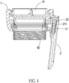
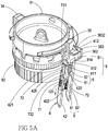
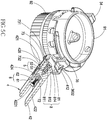
- the adaptor body 3 is a wider-top-narrower-bottomed annular body and a ledge 33 extends inwardly at the bottom thereof, wherein the adaptor body 3 includes an inner wall surface 31 and an outer wall surface 32, two corresponding buckles 34, 35 are configured on a top surface, the outer wall surface 32 has a pivotal connection seat 36, the pivotal connection seat 36 has two corresponding lugs 361, 362 and a cover 363 connecting the top surfaces of such two lugs 361, 362, such that an accommodation space is formed between the two lugs 361, 362 and the cover 363, and a first through-hole 3611 and corresponding second through-hole 3621 are respectively configured on the lugs 361 and 362, a mounting hole 36
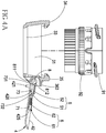
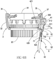
- the pivotal connection seat 36 of the adaptor body 3 is connected to a snap-fit handle 4 which includes a head part 41 and a handle body 42, wherein the head part 41 has a horizontal shaft hole 411 and a head part through-hole 412, a snap member 421 extending from the handle body (42) towards the adaptor body (3) and a mounting part 422 having a mounting part through-hole 4221 and the inside of the handle body 42 is also configured with a vertical channel 423 corresponding to the head part through-hole 412; moreover, a sidewall surface of the handle body 42 is configured with an accommodation hole 424 penetrating into the mounting part 422, and the surrounding area of a sidewall surface on the handle body 42 at the accommodation hole 424 is further formed with a movement space 425, such that the head part 41 of the snap-fit handle 4 can be combined into the accommodation space in the pivotal connection seat 36 of the adaptor body 3 thereby allowing the horizontal shaft hole 411 of the head part 41 to correspond to the first through-hole 3611 and the second
- an upper latch pin assembly 5 may further penetrate into the head part through-hole 412 of the head part 41, and the upper latch pin assembly 5 comprises an upper latch pin component 51 and an elastic component 52, in which the elastic component 52 can be sleeve placed onto the upper latch pin component 51 and inserted into the vertical channel 423 of the handle body 42 via the head part through-hole 412 on the head part 41 of the snap-fit handle 4.
- a push board 7 can vertically move within the movement space 425 and include a push plate body 71, an insertion plate 72 having an opening 721 extends from the push plate body 71 towards the snap-fit handle 4 so as to penetrate into the accommodation hole 424 on a sidewall surface of the handle body 42, and a positioning plate 73 extends upwardly from the push plate body 71, wherein the top surface 731 of the positioning plate 73 acts as a guiding surface (the movement space 425 has a narrower-top-wider-bottomed structure, and the structural width at the narrower portion thereof corresponds to the width of the positioning plate 73), and the guiding surface may be an inclined surface.
- a lower latch pin assembly 6 may further penetrate the mounting part through-hole 4221 on the mounting part 422 of the handle body 42, which includes a lower latch pin component 61 and an elastic component 62, wherein the elastic component 62 of the lower latch pin assembly 6 can be sleeve placed onto the lower latch pin component 61 and inserted into the accommodation hole 424 of the handle body 42 via the mounting part through-hole on the mounting part 422 of the handle body 42 so that the front end of the lower latch pin component 61 can go through the opening 721 of the insertion plate 72 on the push board 7.
- a pivotal connection shaft 8 can penetrate the first through-hole 3611 and second through-hole 3621 on the lugs 361, 362 of the adaptor body 3 as well as the horizontal shaft hole 411 in the head part 41 of the snap-fit handle 4 (and then further through the mounting hole 3631 and the first positioning hole 815 by means of a stationary axle 3632 so as to fix the pivotal connection shaft 8 into the pivotal connection seat 36 of the adaptor body 3 without rotation), in which a first positioning groove 811 (see A-A in Figure 2A ), a second positioning groove 812, a first abutting surface 813 (see A-A in Figure 2A ), a second abutting surface 814 and a first positioning hole 815 are configured on the shaft body 81 of the pivotal connection shaft 8, and the first positioning groove 811 and the second positioning groove 812 are located on one side of the shaft body 81 of the pivotal connection shaft 8, while the first positioning hole 815 located on the other side of the shaft body 81 of the pivotal connection shaft 8.
- pivotal connection shaft 8 allows the snap-fit handle 4 to rotate on the pivotal connection seat 36 of the adaptor body 3; meanwhile, by controlling the up-down movement of the push board 7, it is possible to switch between the lockup state or unlock state in the snap member 421 of the snap-fit handle 4 and allow the snap member 421 to penetrate into or depart from the inside of the snap hole 37 in the adaptor body 3.
- the snap-fit handle 4 should be in the unlock state, then, after connecting the two pipe joints 91, 92, the adaptor body 3 can be sleeve installed onto the two connected pipe joints 91, 92, then the snap-fit handle 4 is pulled downwardly, as shown in Figure 3B , so that the buckles 34, 35 of the adaptor body 3 can be snap fixed onto the pipe joints 91, 92, wherein, when the snap-fit handle 4 is in the lockup state and perpendicular with respect to the adaptor body 3, the snap member 421 of the snap-fit handle 4 can be inserted into the snap hole 37 of the adaptor body 3; under such a circumstance, the upper latch pin component 51 abuts against the first abutting surface 813 and the snap-fit handle 4 is in the lockup state because the top surface 731 of the positioning plate 73 in the push plate body 71 can insert and
- a push-in standard position marking 426 is denoted on the handle body 42 (indicated by a black dot in the present embodiment, but can be a line segment or other marks to indicate the required standard push-in position), and the positioning plate 73 includes a push-in position mark 732 as well (indicated by a black dot in the present embodiment, but can be a line segment or other marks to represent the position currently being pushed in).
- the top surface 731 of the positioning plate 73 operates as a guiding surface, it is possible to following the arc-wise rotation of the pivotal connection shaft 8 by means of the elastic force generated by the elastic component 52; as a result, when the top surface 731 of the positioning plate 73 engages with the first positioning groove 811 and the upper latch pin component 51 contacts the first abutting surface 813, the elastic components 52, 62 can have sufficient space for elastic restorations thereby naturally pushing the top surface 731 of the positioning plate 73 to be inserted and positioned within the first positioning groove 811 and allowing the upper latch pin component 51 to abut against the first abutting surface 813.
- the snap-fit handle 4 can be perpendicular with respect to the adaptor body 3 and the snap member 421 of the snap-fit handle 4 can be inserted into the snap hole 37 of the adaptor body 3, and further snap latched onto the surface of the pipe joint 92, wherein the pipe joint 92 is fixed by means of the snap member 421, while the pipe joint 92 is secured via the buckles 34, 35 of the adaptor body 3, thus up-down mutually jointed so as to provide a tight snap connection between the two pipe joints 91, 92 thereby eliminating possible loose or detachment issues at the connection portion of such two pipe joints 91, 92.
- the snap-fit positioning structure for pipe joints according to the present invention provides the following advantages:
- the snap-fit positioning structure for pipe joints according to the present invention applies a more stable snap-fit position structure to snap fit two pipe joints in connection, and because of such a special structure, it is possible to effectively prevent the occurrence of loose or detachment issues at the connection portion of the pipe joints, no matter due to human factors, vibrations or impacts from external forces.
Landscapes
- Engineering & Computer Science (AREA)
- General Engineering & Computer Science (AREA)
- Mechanical Engineering (AREA)
- Quick-Acting Or Multi-Walled Pipe Joints (AREA)
Priority Applications (2)
| Application Number | Priority Date | Filing Date | Title |
|---|---|---|---|
| EP16169475.7A EP3244111B1 (en) | 2016-05-13 | 2016-05-13 | Snap-fit positioning structure for pipe joints |
| PL16169475T PL3244111T3 (pl) | 2016-05-13 | 2016-05-13 | Struktura pozycjonowania zatrzaskowego dla złączy rurowych |
Applications Claiming Priority (1)
| Application Number | Priority Date | Filing Date | Title |
|---|---|---|---|
| EP16169475.7A EP3244111B1 (en) | 2016-05-13 | 2016-05-13 | Snap-fit positioning structure for pipe joints |
Publications (2)
| Publication Number | Publication Date |
|---|---|
| EP3244111A1 EP3244111A1 (en) | 2017-11-15 |
| EP3244111B1 true EP3244111B1 (en) | 2020-09-02 |
Family
ID=56026660
Family Applications (1)
| Application Number | Title | Priority Date | Filing Date |
|---|---|---|---|
| EP16169475.7A Active EP3244111B1 (en) | 2016-05-13 | 2016-05-13 | Snap-fit positioning structure for pipe joints |
Country Status (2)
| Country | Link |
|---|---|
| EP (1) | EP3244111B1 (pl) |
| PL (1) | PL3244111T3 (pl) |
Families Citing this family (4)
| Publication number | Priority date | Publication date | Assignee | Title |
|---|---|---|---|---|
| CN108461168B (zh) * | 2018-04-18 | 2023-10-27 | 中国工程物理研究院激光聚变研究中心 | 一种偏心锁紧靶盒 |
| CN112205948B (zh) * | 2019-07-11 | 2025-01-21 | 杭州创辉医疗电子设备有限公司 | 一种卡扣和具有该卡扣的内窥镜 |
| CN114379785B (zh) * | 2021-12-30 | 2024-07-12 | 哈瓦国际航空技术(深圳)有限公司 | 锁扣结构、搭载平台及无人机 |
| WO2026081527A1 (zh) * | 2024-10-18 | 2026-04-23 | 比亚迪股份有限公司 | 流体用联接件 |
Family Cites Families (3)
| Publication number | Priority date | Publication date | Assignee | Title |
|---|---|---|---|---|
| US7828340B2 (en) * | 2006-10-18 | 2010-11-09 | Allegheny Coupling Company | Coupling |
| DE102013200765A1 (de) * | 2013-01-18 | 2014-07-24 | Pfeiffer Vacuum Gmbh | Verbindungsvorrichtung |
| CN203770888U (zh) * | 2014-03-04 | 2014-08-13 | 上虞联广橡塑金属制品有限公司 | 用于管接头的卡扣定位结构 |
-
2016
- 2016-05-13 PL PL16169475T patent/PL3244111T3/pl unknown
- 2016-05-13 EP EP16169475.7A patent/EP3244111B1/en active Active
Non-Patent Citations (1)
| Title |
|---|
| None * |
Also Published As
| Publication number | Publication date |
|---|---|
| EP3244111A1 (en) | 2017-11-15 |
| PL3244111T3 (pl) | 2021-04-19 |
Similar Documents
| Publication | Publication Date | Title |
|---|---|---|
| EP3244111A1 (en) | Snap-fit positioning structure for pipe joints | |
| US9742140B2 (en) | Connector assembly for a plasma arc torch | |
| US20080273922A1 (en) | Arrangement for fixing components detachably to a ceiling or wall | |
| JP2008194450A (ja) | インスリンポンプのためのバヨネット型ルアー係止結合部材 | |
| JP5270129B2 (ja) | 押しボタンスイッチの取付構造 | |
| JP5355471B2 (ja) | エンドキャップ及びモール | |
| CA3087759C (en) | Torque wrench and reaction arm assembly | |
| US9211003B1 (en) | Slide rail assembly | |
| KR20140087420A (ko) | 커넥터 및 이를 구비하는 커넥터 조립체 | |
| US11398702B2 (en) | Connector with interlock circuit | |
| EP3041328A1 (en) | Slide rail assembly | |
| JPH10208806A (ja) | 防水コネクタ | |
| US20160123361A1 (en) | Connector | |
| JP4340328B2 (ja) | 流路連通用ロックコネクタ装置 | |
| US6394814B2 (en) | Electrical plug-in connector for providing an electrical connection between two regions separated by a partition wall | |
| JP2006066155A (ja) | レバースイッチの取付構造 | |
| CN205504289U (zh) | 管接头的卡扣定位结构 | |
| KR20230071421A (ko) | 딘레일 장착구조체 | |
| US7250912B2 (en) | Fixing structure | |
| KR102796356B1 (ko) | 커넥터 | |
| US9991659B2 (en) | Hand-operated tool, ground contact mounting set and method for mounting a terminal onto a ground stud contact, in particular for a car body | |
| KR20160000952U (ko) | 딘레일 탈거기구가 구비된 회로차단기 | |
| JP2006185796A (ja) | 接続状態維持具 | |
| EP1884288A1 (en) | Spray head for manual sprayers | |
| JP4382056B2 (ja) | 牛の鼻輪取付具 |
Legal Events
| Date | Code | Title | Description |
|---|---|---|---|
| PUAI | Public reference made under article 153(3) epc to a published international application that has entered the european phase |
Free format text: ORIGINAL CODE: 0009012 |
|
| STAA | Information on the status of an ep patent application or granted ep patent |
Free format text: STATUS: THE APPLICATION HAS BEEN PUBLISHED |
|
| AK | Designated contracting states |
Kind code of ref document: A1 Designated state(s): AL AT BE BG CH CY CZ DE DK EE ES FI FR GB GR HR HU IE IS IT LI LT LU LV MC MK MT NL NO PL PT RO RS SE SI SK SM TR |
|
| AX | Request for extension of the european patent |
Extension state: BA ME |
|
| STAA | Information on the status of an ep patent application or granted ep patent |
Free format text: STATUS: REQUEST FOR EXAMINATION WAS MADE |
|
| 17P | Request for examination filed |
Effective date: 20180515 |
|
| RBV | Designated contracting states (corrected) |
Designated state(s): AL AT BE BG CH CY CZ DE DK EE ES FI FR GB GR HR HU IE IS IT LI LT LU LV MC MK MT NL NO PL PT RO RS SE SI SK SM TR |
|
| GRAP | Despatch of communication of intention to grant a patent |
Free format text: ORIGINAL CODE: EPIDOSNIGR1 |
|
| STAA | Information on the status of an ep patent application or granted ep patent |
Free format text: STATUS: GRANT OF PATENT IS INTENDED |
|
| RIC1 | Information provided on ipc code assigned before grant |
Ipc: F16L 23/06 20060101AFI20200228BHEP Ipc: F16L 37/20 20060101ALI20200228BHEP |
|
| INTG | Intention to grant announced |
Effective date: 20200324 |
|
| GRAS | Grant fee paid |
Free format text: ORIGINAL CODE: EPIDOSNIGR3 |
|
| GRAA | (expected) grant |
Free format text: ORIGINAL CODE: 0009210 |
|
| STAA | Information on the status of an ep patent application or granted ep patent |
Free format text: STATUS: THE PATENT HAS BEEN GRANTED |
|
| AK | Designated contracting states |
Kind code of ref document: B1 Designated state(s): AL AT BE BG CH CY CZ DE DK EE ES FI FR GB GR HR HU IE IS IT LI LT LU LV MC MK MT NL NO PL PT RO RS SE SI SK SM TR |
|
| REG | Reference to a national code |
Ref country code: GB Ref legal event code: FG4D |
|
| REG | Reference to a national code |
Ref country code: AT Ref legal event code: REF Ref document number: 1309216 Country of ref document: AT Kind code of ref document: T Effective date: 20200915 Ref country code: CH Ref legal event code: EP |
|
| REG | Reference to a national code |
Ref country code: DE Ref legal event code: R096 Ref document number: 602016043051 Country of ref document: DE |
|
| REG | Reference to a national code |
Ref country code: IE Ref legal event code: FG4D |
|
| REG | Reference to a national code |
Ref country code: NL Ref legal event code: FP |
|
| REG | Reference to a national code |
Ref country code: LT Ref legal event code: MG4D |
|
| PG25 | Lapsed in a contracting state [announced via postgrant information from national office to epo] |
Ref country code: GR Free format text: LAPSE BECAUSE OF FAILURE TO SUBMIT A TRANSLATION OF THE DESCRIPTION OR TO PAY THE FEE WITHIN THE PRESCRIBED TIME-LIMIT Effective date: 20201203 Ref country code: NO Free format text: LAPSE BECAUSE OF FAILURE TO SUBMIT A TRANSLATION OF THE DESCRIPTION OR TO PAY THE FEE WITHIN THE PRESCRIBED TIME-LIMIT Effective date: 20201202 Ref country code: BG Free format text: LAPSE BECAUSE OF FAILURE TO SUBMIT A TRANSLATION OF THE DESCRIPTION OR TO PAY THE FEE WITHIN THE PRESCRIBED TIME-LIMIT Effective date: 20201202 Ref country code: SE Free format text: LAPSE BECAUSE OF FAILURE TO SUBMIT A TRANSLATION OF THE DESCRIPTION OR TO PAY THE FEE WITHIN THE PRESCRIBED TIME-LIMIT Effective date: 20200902 Ref country code: FI Free format text: LAPSE BECAUSE OF FAILURE TO SUBMIT A TRANSLATION OF THE DESCRIPTION OR TO PAY THE FEE WITHIN THE PRESCRIBED TIME-LIMIT Effective date: 20200902 Ref country code: LT Free format text: LAPSE BECAUSE OF FAILURE TO SUBMIT A TRANSLATION OF THE DESCRIPTION OR TO PAY THE FEE WITHIN THE PRESCRIBED TIME-LIMIT Effective date: 20200902 Ref country code: HR Free format text: LAPSE BECAUSE OF FAILURE TO SUBMIT A TRANSLATION OF THE DESCRIPTION OR TO PAY THE FEE WITHIN THE PRESCRIBED TIME-LIMIT Effective date: 20200902 |
|
| REG | Reference to a national code |
Ref country code: AT Ref legal event code: MK05 Ref document number: 1309216 Country of ref document: AT Kind code of ref document: T Effective date: 20200902 |
|
| PG25 | Lapsed in a contracting state [announced via postgrant information from national office to epo] |
Ref country code: LV Free format text: LAPSE BECAUSE OF FAILURE TO SUBMIT A TRANSLATION OF THE DESCRIPTION OR TO PAY THE FEE WITHIN THE PRESCRIBED TIME-LIMIT Effective date: 20200902 Ref country code: RS Free format text: LAPSE BECAUSE OF FAILURE TO SUBMIT A TRANSLATION OF THE DESCRIPTION OR TO PAY THE FEE WITHIN THE PRESCRIBED TIME-LIMIT Effective date: 20200902 |
|
| PG25 | Lapsed in a contracting state [announced via postgrant information from national office to epo] |
Ref country code: SM Free format text: LAPSE BECAUSE OF FAILURE TO SUBMIT A TRANSLATION OF THE DESCRIPTION OR TO PAY THE FEE WITHIN THE PRESCRIBED TIME-LIMIT Effective date: 20200902 Ref country code: RO Free format text: LAPSE BECAUSE OF FAILURE TO SUBMIT A TRANSLATION OF THE DESCRIPTION OR TO PAY THE FEE WITHIN THE PRESCRIBED TIME-LIMIT Effective date: 20200902 Ref country code: PT Free format text: LAPSE BECAUSE OF FAILURE TO SUBMIT A TRANSLATION OF THE DESCRIPTION OR TO PAY THE FEE WITHIN THE PRESCRIBED TIME-LIMIT Effective date: 20210104 Ref country code: CZ Free format text: LAPSE BECAUSE OF FAILURE TO SUBMIT A TRANSLATION OF THE DESCRIPTION OR TO PAY THE FEE WITHIN THE PRESCRIBED TIME-LIMIT Effective date: 20200902 Ref country code: EE Free format text: LAPSE BECAUSE OF FAILURE TO SUBMIT A TRANSLATION OF THE DESCRIPTION OR TO PAY THE FEE WITHIN THE PRESCRIBED TIME-LIMIT Effective date: 20200902 |
|
| PG25 | Lapsed in a contracting state [announced via postgrant information from national office to epo] |
Ref country code: IS Free format text: LAPSE BECAUSE OF FAILURE TO SUBMIT A TRANSLATION OF THE DESCRIPTION OR TO PAY THE FEE WITHIN THE PRESCRIBED TIME-LIMIT Effective date: 20210102 Ref country code: AT Free format text: LAPSE BECAUSE OF FAILURE TO SUBMIT A TRANSLATION OF THE DESCRIPTION OR TO PAY THE FEE WITHIN THE PRESCRIBED TIME-LIMIT Effective date: 20200902 Ref country code: AL Free format text: LAPSE BECAUSE OF FAILURE TO SUBMIT A TRANSLATION OF THE DESCRIPTION OR TO PAY THE FEE WITHIN THE PRESCRIBED TIME-LIMIT Effective date: 20200902 Ref country code: ES Free format text: LAPSE BECAUSE OF FAILURE TO SUBMIT A TRANSLATION OF THE DESCRIPTION OR TO PAY THE FEE WITHIN THE PRESCRIBED TIME-LIMIT Effective date: 20200902 |
|
| REG | Reference to a national code |
Ref country code: DE Ref legal event code: R097 Ref document number: 602016043051 Country of ref document: DE |
|
| PG25 | Lapsed in a contracting state [announced via postgrant information from national office to epo] |
Ref country code: SK Free format text: LAPSE BECAUSE OF FAILURE TO SUBMIT A TRANSLATION OF THE DESCRIPTION OR TO PAY THE FEE WITHIN THE PRESCRIBED TIME-LIMIT Effective date: 20200902 |
|
| PLBE | No opposition filed within time limit |
Free format text: ORIGINAL CODE: 0009261 |
|
| STAA | Information on the status of an ep patent application or granted ep patent |
Free format text: STATUS: NO OPPOSITION FILED WITHIN TIME LIMIT |
|
| 26N | No opposition filed |
Effective date: 20210603 |
|
| PG25 | Lapsed in a contracting state [announced via postgrant information from national office to epo] |
Ref country code: SI Free format text: LAPSE BECAUSE OF FAILURE TO SUBMIT A TRANSLATION OF THE DESCRIPTION OR TO PAY THE FEE WITHIN THE PRESCRIBED TIME-LIMIT Effective date: 20200902 Ref country code: DK Free format text: LAPSE BECAUSE OF FAILURE TO SUBMIT A TRANSLATION OF THE DESCRIPTION OR TO PAY THE FEE WITHIN THE PRESCRIBED TIME-LIMIT Effective date: 20200902 |
|
| PG25 | Lapsed in a contracting state [announced via postgrant information from national office to epo] |
Ref country code: IT Free format text: LAPSE BECAUSE OF FAILURE TO SUBMIT A TRANSLATION OF THE DESCRIPTION OR TO PAY THE FEE WITHIN THE PRESCRIBED TIME-LIMIT Effective date: 20200902 |
|
| REG | Reference to a national code |
Ref country code: CH Ref legal event code: PL |
|
| GBPC | Gb: european patent ceased through non-payment of renewal fee |
Effective date: 20210513 |
|
| PG25 | Lapsed in a contracting state [announced via postgrant information from national office to epo] |
Ref country code: CH Free format text: LAPSE BECAUSE OF NON-PAYMENT OF DUE FEES Effective date: 20210531 Ref country code: LI Free format text: LAPSE BECAUSE OF NON-PAYMENT OF DUE FEES Effective date: 20210531 Ref country code: MC Free format text: LAPSE BECAUSE OF FAILURE TO SUBMIT A TRANSLATION OF THE DESCRIPTION OR TO PAY THE FEE WITHIN THE PRESCRIBED TIME-LIMIT Effective date: 20200902 Ref country code: LU Free format text: LAPSE BECAUSE OF NON-PAYMENT OF DUE FEES Effective date: 20210513 |
|
| PG25 | Lapsed in a contracting state [announced via postgrant information from national office to epo] |
Ref country code: IE Free format text: LAPSE BECAUSE OF NON-PAYMENT OF DUE FEES Effective date: 20210513 Ref country code: GB Free format text: LAPSE BECAUSE OF NON-PAYMENT OF DUE FEES Effective date: 20210513 |
|
| PG25 | Lapsed in a contracting state [announced via postgrant information from national office to epo] |
Ref country code: FR Free format text: LAPSE BECAUSE OF NON-PAYMENT OF DUE FEES Effective date: 20210531 |
|
| PG25 | Lapsed in a contracting state [announced via postgrant information from national office to epo] |
Ref country code: HU Free format text: LAPSE BECAUSE OF FAILURE TO SUBMIT A TRANSLATION OF THE DESCRIPTION OR TO PAY THE FEE WITHIN THE PRESCRIBED TIME-LIMIT; INVALID AB INITIO Effective date: 20160513 |
|
| PG25 | Lapsed in a contracting state [announced via postgrant information from national office to epo] |
Ref country code: CY Free format text: LAPSE BECAUSE OF FAILURE TO SUBMIT A TRANSLATION OF THE DESCRIPTION OR TO PAY THE FEE WITHIN THE PRESCRIBED TIME-LIMIT Effective date: 20200902 |
|
| PG25 | Lapsed in a contracting state [announced via postgrant information from national office to epo] |
Ref country code: MK Free format text: LAPSE BECAUSE OF FAILURE TO SUBMIT A TRANSLATION OF THE DESCRIPTION OR TO PAY THE FEE WITHIN THE PRESCRIBED TIME-LIMIT Effective date: 20200902 |
|
| PG25 | Lapsed in a contracting state [announced via postgrant information from national office to epo] |
Ref country code: MT Free format text: LAPSE BECAUSE OF FAILURE TO SUBMIT A TRANSLATION OF THE DESCRIPTION OR TO PAY THE FEE WITHIN THE PRESCRIBED TIME-LIMIT Effective date: 20200902 |
|
| PG25 | Lapsed in a contracting state [announced via postgrant information from national office to epo] |
Ref country code: TR Free format text: LAPSE BECAUSE OF FAILURE TO SUBMIT A TRANSLATION OF THE DESCRIPTION OR TO PAY THE FEE WITHIN THE PRESCRIBED TIME-LIMIT Effective date: 20200902 |
|
| PGFP | Annual fee paid to national office [announced via postgrant information from national office to epo] |
Ref country code: NL Payment date: 20260530 Year of fee payment: 11 |
|
| PGFP | Annual fee paid to national office [announced via postgrant information from national office to epo] |
Ref country code: PL Payment date: 20260602 Year of fee payment: 11 |
|
| PGFP | Annual fee paid to national office [announced via postgrant information from national office to epo] |
Ref country code: DE Payment date: 20260601 Year of fee payment: 11 |
|
| PGFP | Annual fee paid to national office [announced via postgrant information from national office to epo] |
Ref country code: BE Payment date: 20260530 Year of fee payment: 11 |