EP3244143A1 - Dispositif de refroidissement - Google Patents
Dispositif de refroidissement Download PDFInfo
- Publication number
- EP3244143A1 EP3244143A1 EP17167700.8A EP17167700A EP3244143A1 EP 3244143 A1 EP3244143 A1 EP 3244143A1 EP 17167700 A EP17167700 A EP 17167700A EP 3244143 A1 EP3244143 A1 EP 3244143A1
- Authority
- EP
- European Patent Office
- Prior art keywords
- pressure
- fan
- compressors
- circuit module
- condenser
- Prior art date
- Legal status (The legal status is an assumption and is not a legal conclusion. Google has not performed a legal analysis and makes no representation as to the accuracy of the status listed.)
- Withdrawn
Links
Images


Classifications
-
- F—MECHANICAL ENGINEERING; LIGHTING; HEATING; WEAPONS; BLASTING
- F25—REFRIGERATION OR COOLING; COMBINED HEATING AND REFRIGERATION SYSTEMS; HEAT PUMP SYSTEMS; MANUFACTURE OR STORAGE OF ICE; LIQUEFACTION SOLIDIFICATION OF GASES
- F25B—REFRIGERATION MACHINES, PLANTS OR SYSTEMS; COMBINED HEATING AND REFRIGERATION SYSTEMS; HEAT PUMP SYSTEMS
- F25B49/00—Arrangement or mounting of control or safety devices
- F25B49/02—Arrangement or mounting of control or safety devices for compression type machines, plants or systems
- F25B49/027—Condenser control arrangements
-
- F—MECHANICAL ENGINEERING; LIGHTING; HEATING; WEAPONS; BLASTING
- F25—REFRIGERATION OR COOLING; COMBINED HEATING AND REFRIGERATION SYSTEMS; HEAT PUMP SYSTEMS; MANUFACTURE OR STORAGE OF ICE; LIQUEFACTION SOLIDIFICATION OF GASES
- F25B—REFRIGERATION MACHINES, PLANTS OR SYSTEMS; COMBINED HEATING AND REFRIGERATION SYSTEMS; HEAT PUMP SYSTEMS
- F25B2400/00—Component parts or details not otherwise provided for in this subclass
- F25B2400/07—Details of compressors or related parts
- F25B2400/075—Details of compressors or related parts with parallel compressors
-
- F—MECHANICAL ENGINEERING; LIGHTING; HEATING; WEAPONS; BLASTING
- F25—REFRIGERATION OR COOLING; COMBINED HEATING AND REFRIGERATION SYSTEMS; HEAT PUMP SYSTEMS; MANUFACTURE OR STORAGE OF ICE; LIQUEFACTION SOLIDIFICATION OF GASES
- F25B—REFRIGERATION MACHINES, PLANTS OR SYSTEMS; COMBINED HEATING AND REFRIGERATION SYSTEMS; HEAT PUMP SYSTEMS
- F25B2500/00—Problems to be solved
- F25B2500/07—Exceeding a certain pressure value in a refrigeration component or cycle
-
- F—MECHANICAL ENGINEERING; LIGHTING; HEATING; WEAPONS; BLASTING
- F25—REFRIGERATION OR COOLING; COMBINED HEATING AND REFRIGERATION SYSTEMS; HEAT PUMP SYSTEMS; MANUFACTURE OR STORAGE OF ICE; LIQUEFACTION SOLIDIFICATION OF GASES
- F25B—REFRIGERATION MACHINES, PLANTS OR SYSTEMS; COMBINED HEATING AND REFRIGERATION SYSTEMS; HEAT PUMP SYSTEMS
- F25B2600/00—Control issues
- F25B2600/11—Fan speed control
- F25B2600/111—Fan speed control of condenser fans
-
- F—MECHANICAL ENGINEERING; LIGHTING; HEATING; WEAPONS; BLASTING
- F25—REFRIGERATION OR COOLING; COMBINED HEATING AND REFRIGERATION SYSTEMS; HEAT PUMP SYSTEMS; MANUFACTURE OR STORAGE OF ICE; LIQUEFACTION SOLIDIFICATION OF GASES
- F25B—REFRIGERATION MACHINES, PLANTS OR SYSTEMS; COMBINED HEATING AND REFRIGERATION SYSTEMS; HEAT PUMP SYSTEMS
- F25B2600/00—Control issues
- F25B2600/11—Fan speed control
- F25B2600/112—Fan speed control of evaporator fans
-
- F—MECHANICAL ENGINEERING; LIGHTING; HEATING; WEAPONS; BLASTING
- F25—REFRIGERATION OR COOLING; COMBINED HEATING AND REFRIGERATION SYSTEMS; HEAT PUMP SYSTEMS; MANUFACTURE OR STORAGE OF ICE; LIQUEFACTION SOLIDIFICATION OF GASES
- F25B—REFRIGERATION MACHINES, PLANTS OR SYSTEMS; COMBINED HEATING AND REFRIGERATION SYSTEMS; HEAT PUMP SYSTEMS
- F25B2600/00—Control issues
- F25B2600/25—Control of valves
- F25B2600/2513—Expansion valves
-
- F—MECHANICAL ENGINEERING; LIGHTING; HEATING; WEAPONS; BLASTING
- F25—REFRIGERATION OR COOLING; COMBINED HEATING AND REFRIGERATION SYSTEMS; HEAT PUMP SYSTEMS; MANUFACTURE OR STORAGE OF ICE; LIQUEFACTION SOLIDIFICATION OF GASES
- F25B—REFRIGERATION MACHINES, PLANTS OR SYSTEMS; COMBINED HEATING AND REFRIGERATION SYSTEMS; HEAT PUMP SYSTEMS
- F25B2700/00—Sensing or detecting of parameters; Sensors therefor
- F25B2700/19—Pressures
- F25B2700/193—Pressures of the compressor
- F25B2700/1931—Discharge pressures
-
- F—MECHANICAL ENGINEERING; LIGHTING; HEATING; WEAPONS; BLASTING
- F25—REFRIGERATION OR COOLING; COMBINED HEATING AND REFRIGERATION SYSTEMS; HEAT PUMP SYSTEMS; MANUFACTURE OR STORAGE OF ICE; LIQUEFACTION SOLIDIFICATION OF GASES
- F25B—REFRIGERATION MACHINES, PLANTS OR SYSTEMS; COMBINED HEATING AND REFRIGERATION SYSTEMS; HEAT PUMP SYSTEMS
- F25B2700/00—Sensing or detecting of parameters; Sensors therefor
- F25B2700/19—Pressures
- F25B2700/197—Pressures of the evaporator
-
- Y—GENERAL TAGGING OF NEW TECHNOLOGICAL DEVELOPMENTS; GENERAL TAGGING OF CROSS-SECTIONAL TECHNOLOGIES SPANNING OVER SEVERAL SECTIONS OF THE IPC; TECHNICAL SUBJECTS COVERED BY FORMER USPC CROSS-REFERENCE ART COLLECTIONS [XRACs] AND DIGESTS
- Y02—TECHNOLOGIES OR APPLICATIONS FOR MITIGATION OR ADAPTATION AGAINST CLIMATE CHANGE
- Y02B—CLIMATE CHANGE MITIGATION TECHNOLOGIES RELATED TO BUILDINGS, e.g. HOUSING, HOUSE APPLIANCES OR RELATED END-USER APPLICATIONS
- Y02B30/00—Energy efficient heating, ventilation or air conditioning [HVAC]
- Y02B30/70—Efficient control or regulation technologies, e.g. for control of refrigerant flow, motor or heating
Definitions
- the present invention relates to a cooling device, in particular a cooling device for a transport unit, according to the preamble of claim 1.
- cooling devices or refrigeration systems have powerful compressors in their refrigeration circuit.
- a power reduction of the compressor is necessary. This is conventionally realized by a speed reduction, the use of a bypass or other measures reducing the refrigerant mass flow to the heat exchangers.
- the cooling device comprises at least one cooling circuit module with at least one cooling circuit, wherein the cooling circuit module has two compressors connected in parallel.
- the cooling device is characterized in that the two compressors connected in parallel are independently switchable.
- the cooling circuit module is not limited to the exact number of two compressors connected in parallel, but may have two or more compressors connected in parallel with each other.
- Two or more compressors per refrigeration module allow to set the required refrigeration capacity exactly as it is also possible to switch off one of the several compressors or to operate not all compressors. For example, when operating only a portion of the compressors present in the refrigeration cycle, the effective heat-transferring area is relatively increased.
- the cooling device comprises at least one second cooling circuit module which, like the first cooling circuit module, has at least two compressors connected in parallel.
- This construction is particularly flexible and can be a special due to the additional presence of the other condenser and condensers Provide low cooling capacity, if necessary. Thus, at high outside temperatures, the air drawn in for the cooling of the condenser is often too warm to maintain the refrigerant circuit.
- the at least one cooling circuit module comprises an evaporator, a condenser and a throttle.
- the refrigeration circuit module describes a refrigerant circuit in which a refrigerant circulates.
- the refrigerant is typically supplied by means of a compressor under increased pressure to a condenser.
- the gaseous refrigerant condenses on the condenser and changes to the liquid state.
- the energy released during the phase change is dissipated to the outside of the condenser to the ambient air via heat.
- the pressure state of the refrigerant changes abruptly, so that the evaporation temperature of the refrigerant is lowered.
- the energy required for the transition in the gaseous state is removed from the ambient air of the evaporator, resulting in a reduction in temperature in the environment of the evaporator. Subsequently, the gaseous refrigerant is sucked in again by the compressor and the cycle starts from the beginning.
- the refrigeration circuit module comprises a throttle in the form of an expansion valve, preferably in the form of an electronic expansion valve.
- the refrigeration circuit module has a variable speed fan for pressurizing an evaporator with air and / or a variable speed fan for applying a condenser with air so that an air quantity to be delivered by the respective fan can be set as a function of the speed of the fan.
- the device comprises a control unit for influencing a pressure in the refrigeration circuit of the at least one refrigeration circuit module.
- control unit it is possible, for example, for the control unit to be designed to control an evaporator fan, a condenser fan or to communicate with the at least two compressors and to actuate them accordingly, depending on the pressure.
- the device has a means for determining a pressure in the refrigeration circuit of the at least one refrigeration circuit module.
- the means for determining the pressure is a pressure sensor which measures the pressure prevailing in the refrigerant circuit and transmits the measured pressure value to the control unit.
- the control unit undertakes appropriate control actions to maintain the pressure below a critical pressure value. If the pressure were to rise above the critical pressure value, it would be necessary to switch off the cooling device in order to protect it from being damaged by the excessive pressure.
- control unit is adapted to change a speed of a condenser fan and / or a speed of an evaporator fan depending on a pressure in the refrigerant circuit of the at least one refrigeration circuit module.
- the control of the fan on the condenser / condenser controls the load applied and thus the heat which has to be dissipated at the condenser in addition to the input power of the compressor. Varying the amount of air flow directed to the condenser thus has an influence on the pressure prevailing in the refrigerant circuit. If you increase the speed of the condenser fan, the efficiently dissipated during the condensation process of the refrigerant heat energy, thereby counteracting a further increase in the pressure level in the refrigerant circuit.
- control unit is adapted to change an opening state of a throttle in the refrigeration cycle in response to a pressure in the refrigeration circuit of the at least one refrigeration cycle to regulate a refrigerant mass flow in the refrigeration cycle.
- a throttle in the refrigerant circuit By further opening or closing a throttle in the refrigerant circuit, it is possible to compensate for the prevailing in the refrigerant circuit pressure level. If, for example, the pressure level rises in a critical range, opening the throttle with a concomitant increase in the refrigerant mass flow flowing through the throttle leads to a pressure reduction. This is mainly due to the typical architecture of the refrigeration circuit, in which the at least two compressors connected in parallel are short-circuited via the throttle (as well as all other components mentioned above). Opening the throttle thus reduces the pressure in the high pressure region of the refrigerant circuit, which extends from the output of a compressor to the throttle.
- control unit is designed to put at least one of the compressors in an on state or an off state and / or a compressor cycle of at least one of the compressors depending on a pressure in the refrigerant circuit of the at least one refrigeration circuit module to change, preferably reduce.
- the presence of at least two compressors per refrigeration circuit provides a very effective means of adjusting the refrigeration capacity by providing the ability to shut off one of the at least two compressors.
- the effective, heat-transferring area which is mainly due to the condenser, is increased for the compressor (s) not switched off.
- the timing of a compressor can be varied in order to achieve a stable level in the case of a critical pressure level in the refrigerant circuit.
- control unit is designed to rotate the condenser fan at maximum speed when a predetermined pressure is exceeded.
- Maximum condenser ventilation achieved by driving the speed of the condenser fan to its maximum value, effectively removes the heat released to the air near the condenser, which is created during the condensation process of the refrigerant.
- control unit when a predetermined pressure is exceeded, the control unit is configured to rotate or stop the evaporator fan at a minimum speed.
- control unit is designed, when a predetermined pressure is exceeded, to transfer one of the at least two compressors from an on state to an off state and / or to reduce a compressor cycle.
- the selective switching off of one of a plurality of compressors associated with a refrigeration circuit has a direct effect on the refrigeration capacity generated by the refrigeration circuit, so that at a low power requirement no excess of the refrigeration capacity is generated, which is typically responsible for the rise of a pressure level in the refrigerant circuit.
- the situation is similar with the reduction of a compressor clock of at least one of the plurality of compressors associated with a refrigeration circuit.
- control unit when a predetermined pressure is exceeded, is further configured to increase a mass flow of the refrigerant in the refrigerant circuit by changing an opening state of a throttle.
- the cooling device is a cooling device for a transport unit, in particular for a refrigerated semitrailer, a refrigerated trailer or a refrigerated transport container.
- Fig. 1 shows a refrigeration circuit module 1, which has a refrigeration circuit.
- the refrigeration circuit module 1 comprises at least one compressor 2, a condenser 4 (also called condenser), a throttle 5 and an evaporator 3. These components are in the order compressor 2, condenser 4, throttle 5, evaporator 3 and again compressor 2 with each other via lines connected and thus form a refrigeration cycle.
- a refrigerant flows, which has a different boiling or condensation temperature in the condenser 4 and the evaporator 3 due to the compression.
- the refrigeration circuit module 1 has an evaporator fan 6, which can act on the evaporator 3 with an air flow.
- the air cooled in the vicinity of the evaporator 3 is blown out, for example, into a space to be cooled and at the same time supplies the surroundings of the evaporator 3 with not yet cooled air or reheated air.
- the condenser 4 may also have a condenser fan 7, which dissipates the air heated by the condenser 4.
- the cooling device of the invention comprises at least two compressors 2 connected in parallel, which can be switched independently of one another. It is therefore not possible to operate all of the at least two compressors 2, so that the total compressor output of the at least two compressors 2 can be varied.
- the refrigeration circuit module 1 shows a filter drier 9, which is arranged between the throttle 5 and the condenser 4.
- a refrigerant tank 8 is located between the filter drier 9 and the condenser 4.
- the pressure on the high-pressure side of the refrigerant circuit which extends from the output of the compressors 2 to the throttle 5, can be effectively controlled.
- one of the two compressors 2 is put into an off state so as not to further increase or lower the pressure level in the refrigeration circuit.
- the advantage here is that despite the shutdown of a compressor 2, the refrigeration cycle continues to circulate. It is thus possible to reduce the cooling capacity of the refrigeration cycle without completely stopping the refrigeration cycle. This is achieved in a particularly advantageous manner by the parallel arrangement of the at least two compressors 2.
- Fig. 2 shows a pyramidal representation, which are arranged on the different means for controlling or influencing the pressure level one above the other.
- the most effective means that is, those which can greatly affect the pressure level, are located at the bottom of the pyramid, with the effectiveness of the agent decreasing towards the top. If one follows all the steps of this pyramid from bottom to top, one also obtains a start procedure of a refrigeration cycle module of the invention at high outside temperatures.
- the most effective means for determining the pressure is therefore the switching on or off of a single compressor.
- the control of the refrigerant mass flow which is preferably caused by a variation of the opening state of the throttle 5, which may be an electronic expansion valve.
- the measure is arranged, according to which the evaporator fan is adjusted during operation of the refrigeration circuit with a compressor 2.
- the next measure is then the switching of the refrigeration cycle from operation with a compressor in the tandem operation so the parallel operation of the two compressors 2.
- Further influencing the pressure factor is then the rules of the evaporator fan 6 provided in a tandem operation refrigeration cycle, the top of the Pyramid is characterized by adjusting the condenser fan 7 to its maximum speed.
- Fig. 3 shows a flowchart for a state if in the high pressure region of the refrigeration cycle, a critical value is exceeded.
- the capacity of the evaporator fan is set to the state that the pressure pHD is equal to the limit pressure pHD, max and at the same time the throttle in the form of an expansion valve is set to an overheat condition.
- the superheat condition of the throttle or the expansion valve is a state in which the throttle is open or slightly more open compared to its previous position.
- S7 then proceeds, wherein it is checked here whether the rotational speed of the evaporator fan is below a lower threshold RPM, min. If not, it is checked in S8 whether the rotational speed RPM is greater than an upper threshold RPM, max of the evaporator fan. If this is not the case, the system branches again to S6. If the condition checked in S8 is satisfied, the system branches to S9 and proceeds to a continuous operating mode.
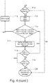
- Fig. 4 shows a flow chart for starting a cooling device at a high outside temperature. For better clarity, the flowchart extends over two pages of the drawing.
- T1 it is decided that a start-up designed for high ambient temperatures is required. Accordingly, in T2, the capacity of the condenser fan is set to maximum, the evaporator fan is put in the off state, the throttle in the form of an electric expansion valve is closed, and both compressors are put in the off state. Starting from this state, it is checked in T3 whether the pressure pHD in the high-pressure zone of the refrigeration circuit is less than or equal to a limiting pressure pHD, max minus a pressure hysteresis value pHyst for clocking a compressor. If this condition is not fulfilled, the system branches to T2.
- the first compressor is started in T4 and subsequently checked again in T5, if the pressure pHD is less than or equal to the limit pressure pHD, max minus the hysteresis pressure pHyst. If this is not the case, the compressor is stopped and the expansion valve is closed (T6) before branching again to T3.
- a branch takes place in T7.
- the low pressure pND of the refrigeration cycle is less than or equal to an upper threshold value pND, max of the low pressure minus a hysteresis value pHyst. If this is not the case, the system branches to T5. Otherwise, the position of the throttle is set to accommodate the subsequent conditions, wherein the high pressure value of the refrigeration cycle is smaller than the upper limit pressure of the high pressure value and the low pressure value of the refrigeration cycle is smaller than an upper limit pressure value of the low pressure and the hot gas temperature THG of the compressor is less than one upper threshold of the hot gas temperature THG, max of the compressor is.
- T9 it is checked whether the high pressure value is less than or equal to the upper threshold value of the high pressure minus a hysteresis pressure for clocking a compressor, if the low pressure value is equal to or lower than the upper threshold of a low pressure value minus a hysteresis pressure value for clocking a compressor, and if the Hot gas temperature of the compressor is less than or equal to the upper threshold of the hot gas temperature of the compressor minus a hysteresis value for clocking the compressor. If these conditions are not fulfilled, the system branches to T5.
- the power of the evaporative fan is controlled to reach a high pressure value equal to the upper threshold of the high pressure value and a position of the choke for an overheat condition. It is then checked in T11 whether the revolution speed of the evaporator fan is equal to or greater than a lower threshold value of the revolution speed. If this is not the case, a branch is made in T9.
- T12 it is checked in T12 whether the revolution speed of the evaporator fan is greater than or equal to an upper threshold value of the revolution speed of the evaporator fan. If this is not the case, the system branches to T10. Otherwise, T13 checks if tandem operation of compressors connected in parallel is required. If not, a branch is made in T20 and a continuous mode of operation is continued.
- the evaporator fan power in T17 is set to a state where the high-pressure side pressure is equal to the upper high-pressure side threshold and the expansion valve is set to overheat temperature.
- the revolution speed of the evaporator fan is examined in T17 and checked whether it is greater than or equal to a lower threshold value for the rotational speed of the evaporator fan. If this is not the case, the system branches to T15.
Landscapes
- Engineering & Computer Science (AREA)
- Physics & Mathematics (AREA)
- Mechanical Engineering (AREA)
- Thermal Sciences (AREA)
- General Engineering & Computer Science (AREA)
- Devices That Are Associated With Refrigeration Equipment (AREA)
Applications Claiming Priority (1)
| Application Number | Priority Date | Filing Date | Title |
|---|---|---|---|
| DE102016005958.3A DE102016005958A1 (de) | 2016-05-13 | 2016-05-13 | Kühlvorrichtung |
Publications (1)
| Publication Number | Publication Date |
|---|---|
| EP3244143A1 true EP3244143A1 (fr) | 2017-11-15 |
Family
ID=58632804
Family Applications (1)
| Application Number | Title | Priority Date | Filing Date |
|---|---|---|---|
| EP17167700.8A Withdrawn EP3244143A1 (fr) | 2016-05-13 | 2017-04-24 | Dispositif de refroidissement |
Country Status (2)
| Country | Link |
|---|---|
| EP (1) | EP3244143A1 (fr) |
| DE (1) | DE102016005958A1 (fr) |
Cited By (1)
| Publication number | Priority date | Publication date | Assignee | Title |
|---|---|---|---|---|
| CN116963450A (zh) * | 2022-04-14 | 2023-10-27 | 腾讯科技(深圳)有限公司 | 冷却单元、冷却控制方法、装置、设备、介质及冷却系统 |
Families Citing this family (1)
| Publication number | Priority date | Publication date | Assignee | Title |
|---|---|---|---|---|
| DE102020115273A1 (de) | 2020-06-09 | 2021-12-09 | Stiebel Eltron Gmbh & Co. Kg | Verfahren zum Betrieb einer Kompressionskälteanlage und Kompressionskälteanlage |
Citations (7)
| Publication number | Priority date | Publication date | Assignee | Title |
|---|---|---|---|---|
| EP1452810A1 (fr) * | 2003-02-28 | 2004-09-01 | Delphi Technologies, Inc. | Méthode pour régler la pression de refoulement dans un système de réfrigération à cycle transcritique |
| US20090084120A1 (en) * | 2007-09-28 | 2009-04-02 | Hobart Brothers Company | Parked aircraft climate control system and method |
| EP2306122A1 (fr) * | 2008-06-24 | 2011-04-06 | Mitsubishi Electric Corporation | Appareil à cycle de réfrigération, et climatiseur |
| EP2320151A1 (fr) * | 2008-07-29 | 2011-05-11 | Daikin Industries, Ltd. | Dispositif de climatisation |
| WO2011056371A2 (fr) * | 2009-11-03 | 2011-05-12 | Carrier Corporation | Réduction des pointes de pression pour systèmes de réfrigérant comprenant un échangeur de chaleur à microcanaux |
| WO2015065643A1 (fr) * | 2013-11-04 | 2015-05-07 | Carrier Corporation | Système hybride à énergie cinétique pour transport réfrigéré |
| US20150267953A1 (en) * | 2014-03-21 | 2015-09-24 | Lennox Industries Inc. | System for operating an hvac system having tandem compressors |
Family Cites Families (5)
| Publication number | Priority date | Publication date | Assignee | Title |
|---|---|---|---|---|
| US4621505A (en) * | 1985-08-01 | 1986-11-11 | Hussmann Corporation | Flow-through surge receiver |
| DD266153A1 (de) * | 1987-09-25 | 1989-03-22 | Schkeuditz Masch & Apparate | Energie- und materialeinsparende schaltung einer kaelteanlage fuer universell genutzte kuehlraeume mit gesichertem notbetrieb, insbesondere fuer kuehlfahrzeuge mit autonomer energieversorgung |
| DE4294880T1 (de) * | 1992-04-23 | 1994-06-09 | Richard H Alsenz | Kühlsystem unter Verwendung einer Entspannungsvorrichtung im Verdampfer |
| DE102005036350A1 (de) * | 2004-09-01 | 2006-03-02 | Behr Gmbh & Co. Kg | Kraftfahrzeug-Standklimaanlage |
| DE102007028851A1 (de) * | 2007-06-22 | 2008-12-24 | Konvekta Ag | Klimaanlage |
-
2016
- 2016-05-13 DE DE102016005958.3A patent/DE102016005958A1/de not_active Withdrawn
-
2017
- 2017-04-24 EP EP17167700.8A patent/EP3244143A1/fr not_active Withdrawn
Patent Citations (7)
| Publication number | Priority date | Publication date | Assignee | Title |
|---|---|---|---|---|
| EP1452810A1 (fr) * | 2003-02-28 | 2004-09-01 | Delphi Technologies, Inc. | Méthode pour régler la pression de refoulement dans un système de réfrigération à cycle transcritique |
| US20090084120A1 (en) * | 2007-09-28 | 2009-04-02 | Hobart Brothers Company | Parked aircraft climate control system and method |
| EP2306122A1 (fr) * | 2008-06-24 | 2011-04-06 | Mitsubishi Electric Corporation | Appareil à cycle de réfrigération, et climatiseur |
| EP2320151A1 (fr) * | 2008-07-29 | 2011-05-11 | Daikin Industries, Ltd. | Dispositif de climatisation |
| WO2011056371A2 (fr) * | 2009-11-03 | 2011-05-12 | Carrier Corporation | Réduction des pointes de pression pour systèmes de réfrigérant comprenant un échangeur de chaleur à microcanaux |
| WO2015065643A1 (fr) * | 2013-11-04 | 2015-05-07 | Carrier Corporation | Système hybride à énergie cinétique pour transport réfrigéré |
| US20150267953A1 (en) * | 2014-03-21 | 2015-09-24 | Lennox Industries Inc. | System for operating an hvac system having tandem compressors |
Cited By (1)
| Publication number | Priority date | Publication date | Assignee | Title |
|---|---|---|---|---|
| CN116963450A (zh) * | 2022-04-14 | 2023-10-27 | 腾讯科技(深圳)有限公司 | 冷却单元、冷却控制方法、装置、设备、介质及冷却系统 |
Also Published As
| Publication number | Publication date |
|---|---|
| DE102016005958A1 (de) | 2017-11-16 |
Similar Documents
| Publication | Publication Date | Title |
|---|---|---|
| EP3697635B1 (fr) | Procédé servant à faire fonctionner un circuit frigorifique ainsi qu'une installation de réfrigération de véhicule | |
| DE102015103032B4 (de) | Wärmeverteilungsvorrichtung für ein Fahrzeug | |
| EP3833562B1 (fr) | Procédé de fonctionnement d'une installation de refroidissement pour un véhicule comportant un circuit d'agent réfrigérant comprenant une fonction de pompe à chaleur | |
| EP1526974B1 (fr) | Installation de climatisation pour vehicule automobile | |
| DE102018126933A1 (de) | Dampfeinspritzungswärmepumpe und Steuerverfahren | |
| DE102020203909A1 (de) | Fahrzeugseitige temperatursteuervorrichtung | |
| EP2928710B1 (fr) | Procédé servant à faire fonctionner un circuit de fluide de refroidissement comme une pompe à chaleur | |
| DE102019107192A1 (de) | Steuerungssystem für ein Wärmesystem sowie Verfahren zum Betrieb eines Wärmesystems | |
| DE112017002025B4 (de) | Klimaanlage für ein Fahrzeug | |
| EP2199706B1 (fr) | Appareil de climatisation d'un dispositif de commutation et une méthode d'utilisation de l'appareil | |
| DE112017002008B4 (de) | Klimaanlage für ein Fahrzeug | |
| EP3597019A1 (fr) | Procédé de refroidissement d'un convertisseur, en particulier d'un convertisseur de fréquence dans un circuit de pompe à chaleur | |
| DE102014106864A1 (de) | Steuerverfahren eines Klimatisierungssystems für ein Fahrzeug | |
| DE102017101218A1 (de) | Fahrzeuginnenraumluftklimatisierungs- und batteriekühlsystem | |
| DE102013219146A1 (de) | Fahrzeug-wärmepumpensystem und -steuerverfahren | |
| DE102024100643A1 (de) | Fahrzeuginternes temperatursteuerungssystem | |
| DE102017213973B4 (de) | Verfahren zum Betreiben einer Kälteanlage eines Fahrzeugs mit einem eine Kühl- und Heizfunktion aufweisenden Kältemittelkreislauf | |
| DE102020206728A1 (de) | System zur Regelung eines Thermomanagements in einem elektrifizierten Fahrzeug | |
| DE102016005958A1 (de) | Kühlvorrichtung | |
| DE102016123782B4 (de) | Verfahren zum Steuern eines Klimakompressors | |
| DE102014205005B4 (de) | Verfahren zum Betrieb der Klimaanlage eines Kraftfahrzeugs, Klimaanlage für ein Kraftfahrzeug | |
| EP4227612A1 (fr) | Procédé de contrôle d'un disjoncteur haute pression de sécurité | |
| DE102017208296B4 (de) | Verfahren zur Begrenzung eines aus einem Kältemittelkreislauf einer Fahrzeugklimaanlage austretenden Kältemittels sowie Fahrzeugklimaanlage | |
| DE102023126181A1 (de) | Dampfinjektions-kältemittelsysteme | |
| EP2986460B1 (fr) | Installation de pompe à chaleur pour véhicule et procédé de fonctionnement d'une installation de pompe à chaleur correspondante |
Legal Events
| Date | Code | Title | Description |
|---|---|---|---|
| PUAI | Public reference made under article 153(3) epc to a published international application that has entered the european phase |
Free format text: ORIGINAL CODE: 0009012 |
|
| AK | Designated contracting states |
Kind code of ref document: A1 Designated state(s): AL AT BE BG CH CY CZ DE DK EE ES FI FR GB GR HR HU IE IS IT LI LT LU LV MC MK MT NL NO PL PT RO RS SE SI SK SM TR |
|
| AX | Request for extension of the european patent |
Extension state: BA ME |
|
| 17P | Request for examination filed |
Effective date: 20180515 |
|
| RIN1 | Information on inventor provided before grant (corrected) |
Inventor name: SCHOENHOFER, STEFAN Inventor name: SCHILLING, FLORIAN Inventor name: RADLER, DOMINIK Inventor name: NITTNAUS, FERDINAND |
|
| 17Q | First examination report despatched |
Effective date: 20180710 |
|
| STAA | Information on the status of an ep patent application or granted ep patent |
Free format text: STATUS: THE APPLICATION IS DEEMED TO BE WITHDRAWN |
|
| 18D | Application deemed to be withdrawn |
Effective date: 20190122 |