EP3244502B1 - Gehäusebausatz für elektrische einrichtungen, insbesondere steckvorrichtungen und sicherungen umfassend - Google Patents
Gehäusebausatz für elektrische einrichtungen, insbesondere steckvorrichtungen und sicherungen umfassend Download PDFInfo
- Publication number
- EP3244502B1 EP3244502B1 EP17177970.5A EP17177970A EP3244502B1 EP 3244502 B1 EP3244502 B1 EP 3244502B1 EP 17177970 A EP17177970 A EP 17177970A EP 3244502 B1 EP3244502 B1 EP 3244502B1
- Authority
- EP
- European Patent Office
- Prior art keywords
- housing
- mounting
- kit
- mounting plate
- locking mechanism
- Prior art date
- Legal status (The legal status is an assumption and is not a legal conclusion. Google has not performed a legal analysis and makes no representation as to the accuracy of the status listed.)
- Active
Links
Images




Classifications
-
- H—ELECTRICITY
- H02—GENERATION; CONVERSION OR DISTRIBUTION OF ELECTRIC POWER
- H02G—INSTALLATION OF ELECTRIC CABLES OR LINES, OR OF COMBINED OPTICAL AND ELECTRIC CABLES OR LINES
- H02G3/00—Installations of electric cables or lines or protective tubing therefor in or on buildings, equivalent structures or vehicles
- H02G3/02—Details
- H02G3/08—Distribution boxes; Connection or junction boxes
- H02G3/081—Bases, casings or covers
-
- H—ELECTRICITY
- H05—ELECTRIC TECHNIQUES NOT OTHERWISE PROVIDED FOR
- H05K—PRINTED CIRCUITS; CASINGS OR CONSTRUCTIONAL DETAILS OF ELECTRIC APPARATUS; MANUFACTURE OF ASSEMBLAGES OF ELECTRICAL COMPONENTS
- H05K7/00—Constructional details common to different types of electric apparatus
- H05K7/14—Mounting supporting structure in casing or on frame or rack
- H05K7/1438—Back panels or connecting means therefor; Terminals; Coding means to avoid wrong insertion
-
- H—ELECTRICITY
- H02—GENERATION; CONVERSION OR DISTRIBUTION OF ELECTRIC POWER
- H02G—INSTALLATION OF ELECTRIC CABLES OR LINES, OR OF COMBINED OPTICAL AND ELECTRIC CABLES OR LINES
- H02G3/00—Installations of electric cables or lines or protective tubing therefor in or on buildings, equivalent structures or vehicles
- H02G3/02—Details
- H02G3/08—Distribution boxes; Connection or junction boxes
- H02G3/086—Assembled boxes
-
- H—ELECTRICITY
- H02—GENERATION; CONVERSION OR DISTRIBUTION OF ELECTRIC POWER
- H02G—INSTALLATION OF ELECTRIC CABLES OR LINES, OR OF COMBINED OPTICAL AND ELECTRIC CABLES OR LINES
- H02G3/00—Installations of electric cables or lines or protective tubing therefor in or on buildings, equivalent structures or vehicles
- H02G3/02—Details
- H02G3/08—Distribution boxes; Connection or junction boxes
- H02G3/14—Fastening of cover or lid to box
-
- H—ELECTRICITY
- H02—GENERATION; CONVERSION OR DISTRIBUTION OF ELECTRIC POWER
- H02G—INSTALLATION OF ELECTRIC CABLES OR LINES, OR OF COMBINED OPTICAL AND ELECTRIC CABLES OR LINES
- H02G3/00—Installations of electric cables or lines or protective tubing therefor in or on buildings, equivalent structures or vehicles
- H02G3/02—Details
- H02G3/08—Distribution boxes; Connection or junction boxes
- H02G3/18—Distribution boxes; Connection or junction boxes providing line outlets
- H02G3/185—Floor outlets and access cups
Definitions
- the invention relates to a housing kit for electrical devices, which e.g. Include plugs and fuses.
- Known plug and socket combinations contain a housing having recesses for the installation of plug devices or sockets on its upper side and is set up, for example, for attachment to a wall. If in the housing also electrical fuses, such. Circuit breakers, residual current circuit breakers, fuses, etc., to be housed, it also has a larger rectangular recess for the installation of a hinged transparent window.
- kits for various plug-in device combination eg from the DE 103 10 630 B3 known. Accordingly, a kit disclosed therein comprises a housing with at least one installation opening, a mounting plate on which at least one plug-in device can be mounted and a built-in mounting plate with at least partially transparent material mounting plate, wherein both the mounting plate on which at least one plug-in device can be mounted, as well as designed as a build-in window mounting plate for installation in the mounting hole of the housing are set up.
- Another, in the DE 103 10 630 B3 described kit for plug-in device combinations comprises two differently designed housing, each having at least one similar mounting hole and a mounting plate on which at least one plug-in device can be mounted, and which is adapted for mounting in the mounting hole of the housing.
- plug-in device combinations With regard to any application-specific use of such plug-in device combinations, however, this results in the highest demands on the actual assembly, in particular also in relation to any pre-installation of electrical equipment in the respective housing.
- a kit for a single housing thus suitable for plug-in device mounting plates and mounting plates formed as windows that fit into one and the same housing opening or contained within a kit for at least two differently designed housing mounting plates, each in a housing opening of the fit a housing or in a similar housing opening of the other, differently designed housing is given at a mounting of the plug-in device combinations essentially no more technical security by the components themselves, so that eg pre-installations are installed at the correct positions within the housing, various security measures , Such as minimum distances, are complied with and for electrical equipment within the housing, only the mounting plates with suitability of predetermined for these electrical devices Steckvorrichtun be used.
- An essential object of the invention is therefore a housing kit for electrical equipment such as e.g. to provide for connectors and fuses, which also allows flexible production of combinations of electrical equipment in a housing, but in addition provides technical security elements that are used in the assembly.
- the invention provides a housing kit for electrical devices, in particular for electrical devices, which comprise at least one plug-in device and / or a fuse, comprising a housing base body with a number of mounting holes and a number of mounting plates, wherein at least one mounting plate for Suitability of mounting at least one plug-in device is formed and / or at least one mounting plate is at least partially made of transparent material and / or at least one mounting plate is completely closed and / or at least one mounting plate has ventilation passages and / or at least one mounting plate has a frame on which an actuating flap is pivotally mounted by means of a hinge joint.
- each first coding means of a mounting hole within the housing kit a unique first coding and each second coding means of a mounting plate within the housing kit has a unique second coding, such that within the housing kit every second coding means of a mounting plate to a maximum of a first coding means of a mounting hole is complementary, and at least within the housing kit every second coding means of a mounting plate, which at least partially is made of transparent material, is complementary to a first coding means of another mounting opening, as each second coding means of a mounting plate, which is designed to suit the mounting of at least one plug-in device.
- a significant advantage is thus that an arbitrary and thus false to dangerous arrangement of at least the mounting plates, which are suitable for the assembly of plug devices and the window formed as mounting plates, for example. for underlying fuses, such as Automatic circuit breaker is excluded. Consequently, when mounting a housing kit according to the invention an unintentional, false or dangerous arrangement and the arranged behind these mounting plates facilities in a simple way already in advance and thus easily excludable.
- a particularly preferred embodiment further provides that in at least one mounting plate having frames on which an actuating flap is pivotally mounted, the frame has a locking mechanism cooperating with the actuating flap and a locking mechanism, wherein the locking mechanism prevents activation of the locking mechanism, as long as the Actuation flap is open.
- an actuating flap is only closed by deliberate closing of the same, by a closure mechanism which prevents unwanted closing of the actuating flap.
- the frame further has a seal and the locking mechanism is designed to activate the closing mechanism during pivoting of the actuating flap for closing this actuating flap, so that in the subsequently activated state the latter presses the actuating flap onto the seal during further closing of the actuating flap.
- the locking mechanism in the closed state of the actuating flap, namely for opening the actuating flap, activatable.
- the first and second coding means can be provided in a particularly simple manner already by different sizes and / or shapes of the mounting openings or mounting plates, wherein particularly preferably the first and second coding means are each provided by unique arrangements of pin-like extensions or receptacles for receiving pin-like extensions, so that the sole use of the latter possibility for unique coding can also be used on basically always recurring basic components in the production of the housing base body and the mounting plates.
- first and second coding means are each provided by unique arrangements of pin-like extensions or receptacles for receiving pin-like extensions, so that the sole use of the latter possibility for unique coding can also be used on basically always recurring basic components in the production of the housing base body and the mounting plates.
- initially provisionally arranged pin-like extensions for unique coding can be removed.
- assemblable housing kits for electrical devices in particular for electrical devices which comprise at least one plug-in device and / or a fuse, such as e.g. a circuit breaker, residual current circuit breaker, fuses, etc., described.
- Such housing kits contain a housing base body, which may be constructed in one or more parts and, for example, has an upper housing part and a lower housing part, which are reversibly connected together.
- a housing base body which may be constructed in one or more parts and, for example, has an upper housing part and a lower housing part, which are reversibly connected together.
- FIGS. 1a to 1d show respective upper housing parts of such a housing base body, which are reversibly connectable to a respective lower housing part (not shown).
- Such a housing lower part can be constructed like a box, for example similar to Housing bases according to DE 103 10 630 B3 , It should be noted, however, that depending on the type of electrical equipment to be housed, a lower housing part can be formed with at least one mounting hole in the invention and / or the main body can also be formed in one piece.
- the housing tops according to FIGS. 1a to 1d comprise, in addition to connection means 10, 11 for connection to a suitable housing lower part, in each case a number of installation openings 101 to 104 (FIG. FIG. 1a ), 105 to 107 ( FIG. 1b ), 108 and 109 ( Figure c) and 110 ( Figure 1d ).
- the mounting openings 102a and 102b of the upper housing part on Fig. 1a based kit and the mounting openings 106a and 106b of the upper housing part on Fig. 1b based kit by an additional, suitably permanently previously attached to the upper housing part, in particular molded bar 150 and 152 separated from each other. Accordingly, with an otherwise on Fig. 1a or on Fig. 1b Alternatively, the previous permanent attachment, in particular injection molding, of the web 150 or 152 on the upper housing part is omitted so that, instead of the mounting openings 102a and 102b or 106a and 106b, an installation opening 102 or 106 is present.
- the bridge 150 or 152 offset in parallel, elsewhere, for example, at the indicated with 151 or 153 dashed line previously permanently attached to the upper housing part, in particular injection-molded, so that instead of the illustrated size of the mounting openings 102a, 106a, 102b and 106b, the mounting openings 102a or 106a enlarged or the mounting openings 102b or 106b are reduced.
- a highly individual housing kit can be assembled based on one or on differently designed housing basic bodies with corresponding mounting openings each with unique coding means and with equally unique second coding means owning mounting plates.
- the installation opening 101 has receptacles for receiving pin-like extensions at the predetermined positions 202, 203, 204, 205, 206, 207, 208, 209 and 210.
- the installation opening 101 has no receptacle, but is there rather not suitable for receiving such pin-like extensions.
- the installation opening 102a has receptacles at the same predetermined positions 201, 203, 206, 207 and 208 corresponding to the installation opening 101. At the same predetermined position 202 corresponding to the installation opening 101, however, the installation opening 102a has no receptacle but is there rather not suitable for receiving such pin-like extensions.
- the installation opening 102b has receptacles at the same predetermined positions 204, 205, and 210 corresponding to the installation opening 101. At the same predetermined position 209 corresponding to the installation opening 101, on the other hand, the installation opening 102b has no receptacle but is rather there for Recording of such pin-like extensions not suitable.
- the installation openings 102a and 102b are not separated from one another by the web 150, but together form a single installation opening 102, such an installation opening has receptacles for receiving pin-like extensions at the same predetermined positions 201, 203 corresponding to the installation opening 101, 204, 205, 206, 207, 208 and 210, however, at the predetermined positions 202 and 209 no recordings, but there is not suitable for receiving such pin-like extensions.
- the installation opening 103 has no receptacle at the same predetermined position 203 corresponding to the installation opening 101, but rather is not suitable for receiving such pin-like extensions. At all other predetermined positions with respect to the installation opening 101, the installation opening 103 has a receptacle for receiving pin-like extensions.
- the installation opening 104 has no receptacle at the same predetermined position 204 corresponding to the installation opening 101, but rather is not suitable for receiving such pin-like extensions. At all other predetermined positions with respect to the installation opening 101, the installation opening 104 has a receptacle for receiving pin-like extensions.
- the installation opening 105 has no receptacle at the same predetermined position 205 corresponding to the installation opening 101, but rather is not suitable for receiving such pin-like extensions. At all other predetermined positions with respect to the installation opening 101, the installation opening 105 has a receptacle for receiving pin-like extensions.
- the installation openings 106a, 106b, 107, 108, 109 and 110 also have no receptacle at the same predetermined position 206, 204, 207, 208, 209 or 210 with respect to the installation opening 101, but rather are there for receiving such pin-like extensions not suitable. At all other predetermined positions with respect to the installation opening 101, the installation openings 106a, 106b, 107, 108, 109 and 110 each have a receptacle for receiving pin-like extensions.
- the installation openings 106a and 106b not separated by the web 152 from each other, but together form a single installation opening 106 has such a mounting opening at the same with respect to the installation opening 101 predetermined positions 206 and 204, but there is for Recording of such pin-like extensions not suitable. However, at all other same predetermined positions with respect to the installation openings 101, the installation opening 106 has a receptacle for receiving pin-like extensions.
- first coding means even with the same size, juxtaposed installation openings within a building kit, which only includes a housing body, ie based on, for example Fig. 1a . Fig. 1b . Fig. 1c or Fig. 1d It is always ensured that every first coding device within this building kit with only one housing base is already unique.
- the first coding means also within a building kit with differently designed housing basic bodies, based at least Fig. 1a and Fig. 1d or based on Fig. 1b .
- Fig. 1c and or Fig. 1d always ensure that each first coding means then within this building kit with at least two differently designed housing basic bodies is unique. If, instead of the installation openings 102a and 102b or 106a and 106b, there is in each case an installation opening 102 or 106, then, within a building construction kit with differently designed housing basic bodies, based on Fig. 1a . Fig. 1b . Fig. 1c and or Fig. 1d always ensures that each first coding means is unique within this building kit with differently designed housing basic bodies.
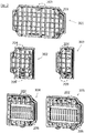
- FIG. 2 Figure 3 shows a number of mounting plates suitable for assembling a housing kit within the scope of the invention, with only sealed mounting plates 301, 302 and 303 and vented mounting plates 304 and 305 shown for simplicity. It should be noted, however, that in the same way also different types of mounting plates are provided for an individually assembled housing kit within the scope of the invention, preferably mounting plates that are suitable for mounting at least one plug device (eg plug or socket), as for example, in of the DE 103 10 630 B3 is described, mounting plates which are at least partially made of transparent material and / or mounting plates having at least one frame on which by means of a hinge joint, an actuating flap is pivotally mounted.
- plug device eg plug or socket
- the mounting plates 301, 302, 303, 304 and 305 each have with respect to the mounting holes according to FIGS. 1a to 1d same predetermined positions 201, 202, 203, 204, 205, 206, 207, 208, 209 or 210 pin-like extensions.
- a housing kit assembled according to the invention in which e.g. a mounting plate 301 is correctly mounted only in the mounting hole 101, therefore, the pin-like extension is there removed at the position 201 for unique coding and the remaining extensions remain earmarked as permanent pin-like extensions.
- another mounting plate 301 can be mounted correctly only in the mounting hole 103, in this further mounting plate 301 is thus removed at the position 203 for unique coding the local pin-like extension and the remaining extensions remain earmarked as permanent pin-like extensions.
- housing kit in which, for example, only the mounting plate 302 is correctly mounted in the mounting hole 102b, therefore, the local pin-like extension is removed at position 209 for unique coding and the remaining extensions remain earmarked and durable. If, on the other hand, a mounting plate contained in a housing set according to the invention and mounted on the mounting plate 302 can only be mounted in the mounting opening 106b, then the pin-like extension is removed at the position 204 for unique coding and the remaining extensions remain earmarked as permanent pen-like extensions.
- the bridge 150 may be permanently permanently attached to the top of the housing 150 parallel to the dashed line marked 151, and if only the mounting plate 303 is to be mounted correctly in the thus reduced mounting opening 102b, then it is correspondingly attached to the mounting plate 303 at the position 209 for unique coding the local pin-like extension removed and the remaining extensions remain earmarked and durable. In a similar way is at one else on Fig.
- the pin-like extension is removed at the position 202 for unique coding and the remaining extensions remain dedicated as permanent pin-like Extensions.
- a mounting plate based on the mounting plate 304 can only be mounted in the mounting opening 106a, then the pin-like extension is removed there at the position 206 for unique coding, and the remaining extensions remain earmarked as permanent pin-like extensions.
- the bridge 150 may be permanently permanently attached to the top of the housing 150 parallel to the dashed line marked 151, and if only the mounting plate 305 is to be correctly mounted in the thus enlarged mounting opening 102a, it will thus be correspondingly attached to the mounting plate 305 at the position 202 for unique coding the local pin-like extension removed and the remaining extensions remain earmarked and durable.
- the bridge 150 may be permanently permanently attached to the top of the housing 150 parallel to the dashed line marked 151, and if only the mounting plate 305 is to be correctly mounted in the thus enlarged mounting opening 102a, it will thus be correspondingly attached to the mounting plate 305 at the position 202 for unique coding the local pin-like extension removed and the remaining extensions remain earmarked and durable.
- each mounting plates are assembled, each having a second unique coding within the housing kit, which ensures in cooperation with the first coding means that within the inventively assembled housing kit every second coding means of a mounting plate to a maximum of a first coding means a mounting hole is formed complementary, and that at least within a housing kit every second coding means of a mounting plate, which is at least partially made of transparent material, complementary to a first coding means of another mounting hole, as every second coding means of a mounting plate, which at least one to the suitability of the assembly Plug device is formed.
- housing kits are made possible in a simple manner, within which each first coding means of a mounting plate to a second encoding means of a mounting hole is complementary formed, so that within the housing kit in each of the number of mounting holes only a single mounting plate from the number of mounting plates is mounted.
- a building kit that includes only a housing body, eg based on Fig. 1a . Fig. 1b . Fig. 1c or Fig. 1d Always make sure that inside the case kit in each of the number of mounting holes only a single mounting plate from the number of mounting plates is mountable.
- every second coding means of a mounting plate within the housing kit is designed to be complementary to at most a first coding means of a mounting opening, so that within the housing kit each of the number of mounting plates can be mounted only in a single mounting opening.
- every second coding means of a mounting plate within the housing kit is designed to be complementary to at most a first coding means of a mounting opening, so that within the housing kit each of the number of mounting plates can be mounted only in a single mounting opening.
- FIG. 3a to 3e show in the context of the invention, various partially sectional views of a second encoding means further mounting plate 306 with a frame 310 in which an actuating flap 311 pivotally and a locking mechanism and a locking mechanism, with the Actuating flap cooperating, are arranged, wherein the locking mechanism preferably prevents activation of the shutter mechanism, as long as the actuating flap is opened.
- Fig. 3a are pin-like extensions on the mounting plate as part of the second coding means, for example, at the same with respect to the mounting hole 101 same predetermined positions 202 and 207 ( Fig. 3a ) to recognize.
- the illustrated actuator flap may be partially made of transparent material to form a window 312.
- the shutter mechanism in the illustrated embodiment comprises two pulleys 350 each rotatably disposed on and rotatable with a rotary lever 360 and aligned with respect to the closed state of the actuator door substantially parallel thereto.
- the actuating flap has a receptacle 314 into which the closure mechanism can engage to close the actuating flap.
- Fig. 3a are the receptacles 314 on the side opposite to the pivot axis 313 side, to which also the shutter mechanism is formed adjacent to the frame.
- Each of the disks 350 has a recessed segment, so that in a rotational position of the disks, the recessed segment in each case points in the direction of the receptacle and thus the disks can not engage in the receptacles 314 (FIG. Fig. 3d ) and in a further rotational position of the discs 350 each of the recessed segment opposite Side of the disc has in the direction of the recordings and thus the discs 350 can engage in the receptacles 314.
- the receptacles 314 are further bounded in each case by a side surface 315 and by an outer surface 316 which in the direction of the installation opening when viewed in the closed state.
- a projection 317 is expediently formed, which in the closed state in a frame disposed on the seal 318 can be pressed. Both the projection 317 and the seal 318 preferably extend all around.
- the locking mechanism comprises in the illustrated embodiment, two hinged to the frame projections 340, wherein each of the projections can be brought into a locked state in which a locking action of the projection 340 is deactivated and can be brought into a swung-out state in which the locking action of the projection 340 is activated is.
- Each of the projections 340 is in this case adjacent to a disc 350 hinged to the frame such that each projection 340 engages in the locked state in a formed on the circumference of the disc 350 groove 351 ( Fig. 3d ) and each projection 340 in the pivoted state is pushed out of this groove 350 formed on the circumference of the disk 350 ( Fig. 3b ).
- the groove 351 is for this purpose formed at a position on the circumference of the disc 350, so that in the locked state of the projections 340 each have the recessed segment in the direction of the receptacle 314 and thus the discs can not engage in the receptacles 314 ( Fig. 3d ). Since the projections 340 in the pivoted state from the on the periphery the disc 350 formed groove 351 are pushed out ( Fig. 3b ), the rotary lever 360 can be rotated in principle, up to the rotational position of the discs 350, in which in each case the opposite side of the recessed segment of a disc in the direction of the recordings.
- the discs 350 can engage in the receptacles 314, wherein in this case also the projection 317 is pressed into the seal 318.
- the discs 350 may be tapered radially outwardly and / or have a pitch at the top and / or bottom thereof. which define a kind of screw thread.
- the rotary lever 360 In order to bring the projections 340 back into the locked state, the rotary lever 360 is rotated again in the opposite direction until each projection 340 engages in the associated groove 351.
- the rotary levers 360 are biased in the locked state of the projections 340 and more relaxed in the pivoted state from the locked state, e.g. by means of a spring means 355, e.g. on the one hand on the rotary lever 360 mounted, can be deflected around this and on the other hand fixed to the frame 310.
- the side surfaces 315 of the receptacles 314 and the protrusions 340 are arranged in relation to one another such that the side surfaces 315 first encounter the protrusions 340 when the actuating flap 311 is closed, and give them away until they have taken the pivoted state and are thus pushed out of the grooves 351 ( Fig. 3b ).
- the rotary lever 360 is thus rotatable, and thus when the actuating flap is closed, the discs 350 can engage in the receptacles 314.
- the spring means 355 can cause the necessary rotation in this case.
- a preferred trained locking and locking mechanism thus operates as follows.
- the protrusions 350 In the open state of the actuating flap ( Fig. 3a ) are the protrusions 350 in the locked state, such as in Fig. 3d so that the recessed segments of the discs 350 face toward the seats 314.
- the locking mechanism thus prevents activation of the locking mechanism as long as the actuating flap is opened.
- the outer surfaces 316 and / or the side surfaces 315 strike the projection 340 and pivot it out of the groove 351, the projection 340 e.g. is driven to the side.
- the locking mechanism is thus configured to activate the locking mechanism during pivoting of the actuating flap 311 for closing the actuating plate, wherein the locking mechanism is again designed, in the then activated state, to press the actuating flap 311 onto the seal 318 when closing the actuating plate.
- the rotary lever 360 serves as an adjusting device, in order to activate the locking mechanism again when the actuating flap 311 is still closed, specifically to deactivate the locking mechanism (FIG. Fig. 3d and 3e ), ie in the example described, until the sides of the discs 350 opposite the recessed segments have been unscrewed from the receptacles 314 and released, so that the actuating flap 311 can be raised and the projection 340 is locked again.
- the locking mechanism then remains activated when the actuating flap is open.
Landscapes
- Engineering & Computer Science (AREA)
- Architecture (AREA)
- Civil Engineering (AREA)
- Structural Engineering (AREA)
- Microelectronics & Electronic Packaging (AREA)
- Connector Housings Or Holding Contact Members (AREA)
- Casings For Electric Apparatus (AREA)
- Fuses (AREA)
- Details Of Connecting Devices For Male And Female Coupling (AREA)
- Telephone Set Structure (AREA)
Priority Applications (5)
| Application Number | Priority Date | Filing Date | Title |
|---|---|---|---|
| RS20200055A RS59975B1 (sr) | 2012-02-03 | 2013-01-29 | Sklop kućišta za električne uređaje, posebno one koji sadrže element za spajanje i učvršćenje |
| SI201331673T SI3244502T1 (sl) | 2012-02-03 | 2013-01-29 | Komplet ohišja za električne priprave, ki obsegajo zlasti vtične naprave in varovalke |
| PL17177970T PL3244502T3 (pl) | 2012-02-03 | 2013-01-29 | Zestaw obudów dla urządzeń elektrycznych, zwłaszcza zawierających urządzenia wtykowe i bezpieczniki |
| SM20200240T SMT202000240T1 (it) | 2012-02-03 | 2013-01-29 | Kit di alloggiamento per dispositivi elettrici, in particolare comprendente prese a innesto e interruttori di sicurezza |
| HRP20192324TT HRP20192324T1 (hr) | 2012-02-03 | 2019-12-23 | Ugradni komplet kućišta za električne uređaje, koji posebno obuhvaća priključke i osigurače |
Applications Claiming Priority (3)
| Application Number | Priority Date | Filing Date | Title |
|---|---|---|---|
| DE202012001075U DE202012001075U1 (de) | 2012-02-03 | 2012-02-03 | Gehäusebausatz für elektrische Einrichtungen, insbesondere Steckvorrichtungen und Sicherungen umfassend |
| EP13702745.4A EP2754215B1 (de) | 2012-02-03 | 2013-01-29 | Gehäusebausatz für elektrische einrichtungen, insbesondere steckvorrichtungen und sicherungen umfassend |
| PCT/EP2013/000253 WO2013113490A2 (de) | 2012-02-03 | 2013-01-29 | Gehäusebausatz für elektrische einrichtungen, insbesondere steckvorrichtungen und sicherungen umfassend |
Related Parent Applications (2)
| Application Number | Title | Priority Date | Filing Date |
|---|---|---|---|
| EP13702745.4A Division EP2754215B1 (de) | 2012-02-03 | 2013-01-29 | Gehäusebausatz für elektrische einrichtungen, insbesondere steckvorrichtungen und sicherungen umfassend |
| EP13702745.4A Division-Into EP2754215B1 (de) | 2012-02-03 | 2013-01-29 | Gehäusebausatz für elektrische einrichtungen, insbesondere steckvorrichtungen und sicherungen umfassend |
Publications (2)
| Publication Number | Publication Date |
|---|---|
| EP3244502A1 EP3244502A1 (de) | 2017-11-15 |
| EP3244502B1 true EP3244502B1 (de) | 2019-12-04 |
Family
ID=45971593
Family Applications (2)
| Application Number | Title | Priority Date | Filing Date |
|---|---|---|---|
| EP17177970.5A Active EP3244502B1 (de) | 2012-02-03 | 2013-01-29 | Gehäusebausatz für elektrische einrichtungen, insbesondere steckvorrichtungen und sicherungen umfassend |
| EP13702745.4A Active EP2754215B1 (de) | 2012-02-03 | 2013-01-29 | Gehäusebausatz für elektrische einrichtungen, insbesondere steckvorrichtungen und sicherungen umfassend |
Family Applications After (1)
| Application Number | Title | Priority Date | Filing Date |
|---|---|---|---|
| EP13702745.4A Active EP2754215B1 (de) | 2012-02-03 | 2013-01-29 | Gehäusebausatz für elektrische einrichtungen, insbesondere steckvorrichtungen und sicherungen umfassend |
Country Status (18)
| Country | Link |
|---|---|
| US (2) | US9595818B2 (da) |
| EP (2) | EP3244502B1 (da) |
| CN (2) | CN104094490B (da) |
| CY (2) | CY1122383T1 (da) |
| DE (1) | DE202012001075U1 (da) |
| DK (2) | DK2754215T3 (da) |
| ES (2) | ES2765416T3 (da) |
| HR (2) | HRP20171569T1 (da) |
| HU (1) | HUE048926T2 (da) |
| IN (1) | IN2014KN01385A (da) |
| LT (2) | LT3244502T (da) |
| NO (1) | NO2854398T3 (da) |
| PL (2) | PL2754215T3 (da) |
| PT (2) | PT2754215T (da) |
| RS (2) | RS59975B1 (da) |
| SI (2) | SI3244502T1 (da) |
| SM (2) | SMT201800001T1 (da) |
| WO (1) | WO2013113490A2 (da) |
Families Citing this family (4)
| Publication number | Priority date | Publication date | Assignee | Title |
|---|---|---|---|---|
| DE102013108206A1 (de) | 2013-07-31 | 2015-02-26 | E-Volo Gmbh | Fluggerät, insbesondere Multicopter und Verwendung eines solchen, insbesondere für ein Flug-Fahrgeschäft |
| DE102013108207A1 (de) | 2013-07-31 | 2015-02-05 | E-Volo Gmbh | Fluggerät, insbesondere Multicopter |
| DE102013108204A1 (de) | 2013-07-31 | 2015-02-05 | E-Volo Gmbh | Bergungsvorrichtung für die Verwendung an einem Fluggerät und Fluggerät, insbesondere Multicopter |
| CN113710015B (zh) * | 2020-05-21 | 2023-04-14 | 上海海拉电子有限公司 | 一种汽车电路板用外壳及汽车控制器 |
Family Cites Families (16)
| Publication number | Priority date | Publication date | Assignee | Title |
|---|---|---|---|---|
| US2300509A (en) * | 1941-06-26 | 1942-11-03 | Excelsior Hardware Company | Fastener with lockable camming hasp |
| DE3817869A1 (de) | 1988-05-26 | 1989-11-30 | Rutenbeck Wilhelm Gmbh & Co | Fernmeldetechnische installationsdose |
| US5736676A (en) * | 1995-07-13 | 1998-04-07 | Stelter; Michael S. | Floor structure electrical junction apparatus |
| DE19716137C1 (de) | 1997-04-17 | 1998-10-22 | Siemens Ag | Modul zum Anschluß von Aktoren und/oder Sensoren |
| US5910642A (en) * | 1997-08-29 | 1999-06-08 | Lucent Technologies Inc. | Expandable enclosure for telecommunications applications |
| JP3344326B2 (ja) * | 1998-09-25 | 2002-11-11 | 松下電工株式会社 | 配線装置台 |
| US20030111476A1 (en) * | 2001-12-19 | 2003-06-19 | Donald Serio | Air sealable container with automatically actuable pressure equalizing valve |
| DE10310630B3 (de) | 2003-03-10 | 2004-12-16 | Aloys Mennekes Anlagengesellschaft Mbh & Co. Kg | Bausatz für eine Steckvorrichtungen-Kombination |
| US6806426B1 (en) * | 2003-08-25 | 2004-10-19 | Arlington Industries, Inc. | Two-way electrical box cover |
| JP4460935B2 (ja) | 2004-04-02 | 2010-05-12 | 東芝モバイルディスプレイ株式会社 | 平面表示装置等の電子・電気製品の製造方法、及びこのための帯状収納体 |
| CN2696182Y (zh) * | 2004-04-06 | 2005-04-27 | 邱万友 | 暗线盒 |
| US20070099492A1 (en) * | 2005-11-01 | 2007-05-03 | Eric Clifton | Easy-access service outlet housings |
| US8277001B2 (en) * | 2006-06-13 | 2012-10-02 | Thureon Limited | Storage unit for electronic devices |
| JP5090685B2 (ja) | 2006-08-02 | 2012-12-05 | 矢崎総業株式会社 | 電気装置の搭載構造 |
| US8210387B2 (en) * | 2009-10-09 | 2012-07-03 | The Stanley Works Israel Ltd. | Organizer |
| CN102098893B (zh) * | 2009-12-14 | 2015-04-08 | 南陵县生产力促进中心有限公司 | 具锁合机构的电子装置 |
-
2012
- 2012-02-03 DE DE202012001075U patent/DE202012001075U1/de not_active Expired - Lifetime
-
2013
- 2013-01-29 SM SM20180001T patent/SMT201800001T1/it unknown
- 2013-01-29 PL PL13702745T patent/PL2754215T3/pl unknown
- 2013-01-29 SI SI201331673T patent/SI3244502T1/sl unknown
- 2013-01-29 SM SM20200240T patent/SMT202000240T1/it unknown
- 2013-01-29 IN IN1385KON2014 patent/IN2014KN01385A/en unknown
- 2013-01-29 CN CN201380007949.8A patent/CN104094490B/zh active Active
- 2013-01-29 WO PCT/EP2013/000253 patent/WO2013113490A2/de not_active Ceased
- 2013-01-29 RS RS20200055A patent/RS59975B1/sr unknown
- 2013-01-29 CN CN201611199056.XA patent/CN107105592B/zh active Active
- 2013-01-29 PL PL17177970T patent/PL3244502T3/pl unknown
- 2013-01-29 ES ES17177970T patent/ES2765416T3/es active Active
- 2013-01-29 HR HRP20171569TT patent/HRP20171569T1/hr unknown
- 2013-01-29 PT PT137027454T patent/PT2754215T/pt unknown
- 2013-01-29 PT PT171779705T patent/PT3244502T/pt unknown
- 2013-01-29 SI SI201330778T patent/SI2754215T1/sl unknown
- 2013-01-29 US US14/370,183 patent/US9595818B2/en active Active
- 2013-01-29 LT LTEP17177970.5T patent/LT3244502T/lt unknown
- 2013-01-29 LT LTEP13702745.4T patent/LT2754215T/lt unknown
- 2013-01-29 DK DK13702745.4T patent/DK2754215T3/da active
- 2013-01-29 EP EP17177970.5A patent/EP3244502B1/de active Active
- 2013-01-29 DK DK17177970.5T patent/DK3244502T3/da active
- 2013-01-29 ES ES13702745.4T patent/ES2640714T3/es active Active
- 2013-01-29 RS RS20170982A patent/RS56442B1/sr unknown
- 2013-01-29 HU HUE17177970A patent/HUE048926T2/hu unknown
- 2013-01-29 EP EP13702745.4A patent/EP2754215B1/de active Active
- 2013-06-11 NO NO13804347A patent/NO2854398T3/no unknown
-
2017
- 2017-01-04 US US15/398,428 patent/US10554028B2/en active Active
- 2017-10-12 CY CY20171101066T patent/CY1122383T1/el unknown
-
2019
- 2019-12-23 HR HRP20192324TT patent/HRP20192324T1/hr unknown
-
2020
- 2020-01-30 CY CY20201100081T patent/CY1122540T1/el unknown
Non-Patent Citations (1)
| Title |
|---|
| None * |
Also Published As
Similar Documents
| Publication | Publication Date | Title |
|---|---|---|
| EP2182144B1 (de) | Tür- oder Fensterbeschlag | |
| DE102020208653A1 (de) | Luftauslass, Heiz- oder Klimaanlage mit einem solchen Luftauslass, Wohnmobil mit Luftauslass, Heiz- und/oder Klimaanlage und Verfahren zum Befestigen, Betreiben und Umbauen eines Luftauslasses | |
| DE19837248A1 (de) | Türschloß für ein elektrisches Haushaltsgerät | |
| EP2754215B1 (de) | Gehäusebausatz für elektrische einrichtungen, insbesondere steckvorrichtungen und sicherungen umfassend | |
| DE19849883B4 (de) | Elektrische Steckdose mit einer Kindersicherung | |
| DE69800329T2 (de) | Gehäuse für elektrische Geräte mit abnehmbarem Deckel und Deckelbefestigungsanordnung | |
| EP3277899A1 (de) | Türgriffanordnung für ein kraftfahrzeug | |
| EP1249570B1 (de) | Verschlussvorrichtung | |
| DE102010017388A1 (de) | Vorrichtung zur Kupplung und Entkupplung eines Türaußendrückers | |
| DE69210072T2 (de) | Elektrisches Verbindergehäuse | |
| DE102007009548A1 (de) | Verschluß-System für eine Leuchtenabdeckung | |
| EP0692846A2 (de) | Verriegelbare Steckverbindung | |
| AT500918B1 (de) | Steckdose mit sicherheitsverschluss und multifunktionsrahmen | |
| DE102019206287A1 (de) | Verschließvorrichtung | |
| EP1994542B1 (de) | Schaltgerät | |
| EP3686908A1 (de) | Elektroinstallationsgerät mit sockelaufsatz | |
| EP3480410A1 (de) | Schlupftür | |
| EP2750269A1 (de) | Pumpenaggregat | |
| DE102011085606B4 (de) | Rotorgehäuse eines elektrischen Schaltgerätes sowie elektrisches Schaltgerät | |
| DE3731588A1 (de) | Steckdose mit abdeckvorrichtung | |
| EP3990738A1 (de) | Gehäuse für einen antrieb sowie antrieb | |
| DE10215940B4 (de) | Schlüsselschalter | |
| DE2805609A1 (de) | Schalter mit einem mehrteiligen gehaeuse | |
| EP0697133A1 (de) | Schalter | |
| DE1165124B (de) | Mehrteilige elektrische Einrichtung |
Legal Events
| Date | Code | Title | Description |
|---|---|---|---|
| PUAI | Public reference made under article 153(3) epc to a published international application that has entered the european phase |
Free format text: ORIGINAL CODE: 0009012 |
|
| STAA | Information on the status of an ep patent application or granted ep patent |
Free format text: STATUS: THE APPLICATION HAS BEEN PUBLISHED |
|
| AC | Divisional application: reference to earlier application |
Ref document number: 2754215 Country of ref document: EP Kind code of ref document: P |
|
| AK | Designated contracting states |
Kind code of ref document: A1 Designated state(s): AL AT BE BG CH CY CZ DE DK EE ES FI FR GB GR HR HU IE IS IT LI LT LU LV MC MK MT NL NO PL PT RO RS SE SI SK SM TR |
|
| STAA | Information on the status of an ep patent application or granted ep patent |
Free format text: STATUS: REQUEST FOR EXAMINATION WAS MADE |
|
| 17P | Request for examination filed |
Effective date: 20180213 |
|
| RBV | Designated contracting states (corrected) |
Designated state(s): AL AT BE BG CH CY CZ DE DK EE ES FI FR GB GR HR HU IE IS IT LI LT LU LV MC MK MT NL NO PL PT RO RS SE SI SK SM TR |
|
| GRAP | Despatch of communication of intention to grant a patent |
Free format text: ORIGINAL CODE: EPIDOSNIGR1 |
|
| STAA | Information on the status of an ep patent application or granted ep patent |
Free format text: STATUS: GRANT OF PATENT IS INTENDED |
|
| RIC1 | Information provided on ipc code assigned before grant |
Ipc: H02G 3/08 20060101AFI20190606BHEP |
|
| INTG | Intention to grant announced |
Effective date: 20190704 |
|
| GRAJ | Information related to disapproval of communication of intention to grant by the applicant or resumption of examination proceedings by the epo deleted |
Free format text: ORIGINAL CODE: EPIDOSDIGR1 |
|
| STAA | Information on the status of an ep patent application or granted ep patent |
Free format text: STATUS: REQUEST FOR EXAMINATION WAS MADE |
|
| GRAS | Grant fee paid |
Free format text: ORIGINAL CODE: EPIDOSNIGR3 |
|
| STAA | Information on the status of an ep patent application or granted ep patent |
Free format text: STATUS: GRANT OF PATENT IS INTENDED |
|
| INTC | Intention to grant announced (deleted) | ||
| GRAP | Despatch of communication of intention to grant a patent |
Free format text: ORIGINAL CODE: EPIDOSNIGR1 |
|
| GRAA | (expected) grant |
Free format text: ORIGINAL CODE: 0009210 |
|
| STAA | Information on the status of an ep patent application or granted ep patent |
Free format text: STATUS: THE PATENT HAS BEEN GRANTED |
|
| INTG | Intention to grant announced |
Effective date: 20191025 |
|
| AC | Divisional application: reference to earlier application |
Ref document number: 2754215 Country of ref document: EP Kind code of ref document: P |
|
| AK | Designated contracting states |
Kind code of ref document: B1 Designated state(s): AL AT BE BG CH CY CZ DE DK EE ES FI FR GB GR HR HU IE IS IT LI LT LU LV MC MK MT NL NO PL PT RO RS SE SI SK SM TR |
|
| REG | Reference to a national code |
Ref country code: GB Ref legal event code: FG4D Free format text: NOT ENGLISH |
|
| REG | Reference to a national code |
Ref country code: CH Ref legal event code: EP |
|
| REG | Reference to a national code |
Ref country code: AT Ref legal event code: REF Ref document number: 1210609 Country of ref document: AT Kind code of ref document: T Effective date: 20191215 |
|
| REG | Reference to a national code |
Ref country code: HR Ref legal event code: TUEP Ref document number: P20192324T Country of ref document: HR |
|
| REG | Reference to a national code |
Ref country code: IE Ref legal event code: FG4D Free format text: LANGUAGE OF EP DOCUMENT: GERMAN |
|
| REG | Reference to a national code |
Ref country code: DE Ref legal event code: R096 Ref document number: 502013014036 Country of ref document: DE |
|
| REG | Reference to a national code |
Ref country code: CH Ref legal event code: NV Representative=s name: BOVARD AG PATENT- UND MARKENANWAELTE, CH |
|
| REG | Reference to a national code |
Ref country code: RO Ref legal event code: EPE |
|
| REG | Reference to a national code |
Ref country code: FI Ref legal event code: FGE |
|
| REG | Reference to a national code |
Ref country code: HR Ref legal event code: ODRP Ref document number: P20192324T Country of ref document: HR Payment date: 20200123 Year of fee payment: 8 |
|
| REG | Reference to a national code |
Ref country code: DK Ref legal event code: T3 Effective date: 20200306 Ref country code: PT Ref legal event code: SC4A Ref document number: 3244502 Country of ref document: PT Date of ref document: 20200309 Kind code of ref document: T Free format text: AVAILABILITY OF NATIONAL TRANSLATION Effective date: 20200302 |
|
| REG | Reference to a national code |
Ref country code: SE Ref legal event code: TRGR |
|
| REG | Reference to a national code |
Ref country code: NL Ref legal event code: FP |
|
| REG | Reference to a national code |
Ref country code: NO Ref legal event code: T2 Effective date: 20191204 |
|
| REG | Reference to a national code |
Ref country code: EE Ref legal event code: FG4A Ref document number: E018859 Country of ref document: EE Effective date: 20200218 |
|
| REG | Reference to a national code |
Ref country code: GR Ref legal event code: EP Ref document number: 20200400226 Country of ref document: GR Effective date: 20200511 |
|
| REG | Reference to a national code |
Ref country code: HR Ref legal event code: T1PR Ref document number: P20192324 Country of ref document: HR |
|
| REG | Reference to a national code |
Ref country code: SK Ref legal event code: T3 Ref document number: E 33658 Country of ref document: SK |
|
| REG | Reference to a national code |
Ref country code: ES Ref legal event code: FG2A Ref document number: 2765416 Country of ref document: ES Kind code of ref document: T3 Effective date: 20200609 |
|
| REG | Reference to a national code |
Ref country code: EE Ref legal event code: HC1A Ref document number: E018859 Country of ref document: EE |
|
| REG | Reference to a national code |
Ref country code: DE Ref legal event code: R097 Ref document number: 502013014036 Country of ref document: DE |
|
| REG | Reference to a national code |
Ref country code: HU Ref legal event code: AG4A Ref document number: E048926 Country of ref document: HU |
|
| PLBE | No opposition filed within time limit |
Free format text: ORIGINAL CODE: 0009261 |
|
| STAA | Information on the status of an ep patent application or granted ep patent |
Free format text: STATUS: NO OPPOSITION FILED WITHIN TIME LIMIT |
|
| 26N | No opposition filed |
Effective date: 20200907 |
|
| REG | Reference to a national code |
Ref country code: HR Ref legal event code: ODRP Ref document number: P20192324 Country of ref document: HR Payment date: 20210119 Year of fee payment: 9 |
|
| REG | Reference to a national code |
Ref country code: HR Ref legal event code: ODRP Ref document number: P20192324 Country of ref document: HR Payment date: 20220121 Year of fee payment: 10 |
|
| REG | Reference to a national code |
Ref country code: HR Ref legal event code: ODRP Ref document number: P20192324 Country of ref document: HR Payment date: 20230117 Year of fee payment: 11 |
|
| P01 | Opt-out of the competence of the unified patent court (upc) registered |
Effective date: 20230524 |
|
| REG | Reference to a national code |
Ref country code: HR Ref legal event code: ODRP Ref document number: P20192324 Country of ref document: HR Payment date: 20240119 Year of fee payment: 12 |
|
| REG | Reference to a national code |
Ref country code: HR Ref legal event code: ODRP Ref document number: P20192324 Country of ref document: HR Payment date: 20250122 Year of fee payment: 13 |
|
| PGFP | Annual fee paid to national office [announced via postgrant information from national office to epo] |
Ref country code: MC Payment date: 20250129 Year of fee payment: 13 |
|
| PGFP | Annual fee paid to national office [announced via postgrant information from national office to epo] |
Ref country code: RO Payment date: 20250115 Year of fee payment: 13 Ref country code: SM Payment date: 20250120 Year of fee payment: 13 Ref country code: LT Payment date: 20250116 Year of fee payment: 13 |
|
| PGFP | Annual fee paid to national office [announced via postgrant information from national office to epo] |
Ref country code: BG Payment date: 20250121 Year of fee payment: 13 |
|
| PGFP | Annual fee paid to national office [announced via postgrant information from national office to epo] |
Ref country code: EE Payment date: 20250121 Year of fee payment: 13 Ref country code: LV Payment date: 20250121 Year of fee payment: 13 Ref country code: SI Payment date: 20250120 Year of fee payment: 13 |
|
| PGFP | Annual fee paid to national office [announced via postgrant information from national office to epo] |
Ref country code: MT Payment date: 20250122 Year of fee payment: 13 |
|
| PGFP | Annual fee paid to national office [announced via postgrant information from national office to epo] |
Ref country code: AL Payment date: 20250117 Year of fee payment: 13 |
|
| PGFP | Annual fee paid to national office [announced via postgrant information from national office to epo] |
Ref country code: CY Payment date: 20250123 Year of fee payment: 13 |
|
| PGFP | Annual fee paid to national office [announced via postgrant information from national office to epo] |
Ref country code: MK Payment date: 20250116 Year of fee payment: 13 |
|
| REG | Reference to a national code |
Ref country code: CH Ref legal event code: U11 Free format text: ST27 STATUS EVENT CODE: U-0-0-U10-U11 (AS PROVIDED BY THE NATIONAL OFFICE) Effective date: 20260201 |
|
| PGFP | Annual fee paid to national office [announced via postgrant information from national office to epo] |
Ref country code: LU Payment date: 20260121 Year of fee payment: 14 Ref country code: NL Payment date: 20260121 Year of fee payment: 14 |
|
| PGFP | Annual fee paid to national office [announced via postgrant information from national office to epo] |
Ref country code: HU Payment date: 20260126 Year of fee payment: 14 |
|
| REG | Reference to a national code |
Ref country code: HR Ref legal event code: ODRP Ref document number: P20192324 Country of ref document: HR Payment date: 20260122 Year of fee payment: 14 |
|
| PGFP | Annual fee paid to national office [announced via postgrant information from national office to epo] |
Ref country code: SE Payment date: 20260121 Year of fee payment: 14 |
|
| PGFP | Annual fee paid to national office [announced via postgrant information from national office to epo] |
Ref country code: GB Payment date: 20260122 Year of fee payment: 14 |
|
| PGFP | Annual fee paid to national office [announced via postgrant information from national office to epo] |
Ref country code: ES Payment date: 20260217 Year of fee payment: 14 |
|
| PGFP | Annual fee paid to national office [announced via postgrant information from national office to epo] |
Ref country code: DE Payment date: 20260128 Year of fee payment: 14 Ref country code: NO Payment date: 20260120 Year of fee payment: 14 Ref country code: IE Payment date: 20260121 Year of fee payment: 14 Ref country code: DK Payment date: 20260121 Year of fee payment: 14 |
|
| PGFP | Annual fee paid to national office [announced via postgrant information from national office to epo] |
Ref country code: AT Payment date: 20260119 Year of fee payment: 14 Ref country code: HR Payment date: 20260122 Year of fee payment: 14 |
|
| PGFP | Annual fee paid to national office [announced via postgrant information from national office to epo] |
Ref country code: FI Payment date: 20260120 Year of fee payment: 14 Ref country code: BE Payment date: 20260121 Year of fee payment: 14 Ref country code: IT Payment date: 20260130 Year of fee payment: 14 |
|
| PGFP | Annual fee paid to national office [announced via postgrant information from national office to epo] |
Ref country code: RS Payment date: 20260121 Year of fee payment: 14 |
|
| PGFP | Annual fee paid to national office [announced via postgrant information from national office to epo] |
Ref country code: FR Payment date: 20260127 Year of fee payment: 14 Ref country code: IS Payment date: 20260121 Year of fee payment: 14 |
|
| PGFP | Annual fee paid to national office [announced via postgrant information from national office to epo] |
Ref country code: TR Payment date: 20260126 Year of fee payment: 14 |
|
| PGFP | Annual fee paid to national office [announced via postgrant information from national office to epo] |
Ref country code: PT Payment date: 20260128 Year of fee payment: 14 Ref country code: CZ Payment date: 20260116 Year of fee payment: 14 Ref country code: CH Payment date: 20260201 Year of fee payment: 14 |
|
| PGFP | Annual fee paid to national office [announced via postgrant information from national office to epo] |
Ref country code: GR Payment date: 20260119 Year of fee payment: 14 Ref country code: PL Payment date: 20260121 Year of fee payment: 14 |
|
| PGFP | Annual fee paid to national office [announced via postgrant information from national office to epo] |
Ref country code: SK Payment date: 20260122 Year of fee payment: 14 |