EP3244504B1 - Schutzvorrichtung gegen vorübergehende überspannungen - Google Patents
Schutzvorrichtung gegen vorübergehende überspannungen Download PDFInfo
- Publication number
- EP3244504B1 EP3244504B1 EP17170561.9A EP17170561A EP3244504B1 EP 3244504 B1 EP3244504 B1 EP 3244504B1 EP 17170561 A EP17170561 A EP 17170561A EP 3244504 B1 EP3244504 B1 EP 3244504B1
- Authority
- EP
- European Patent Office
- Prior art keywords
- varistor
- electrode
- discharge tube
- blade
- spark gap
- Prior art date
- Legal status (The legal status is an assumption and is not a legal conclusion. Google has not performed a legal analysis and makes no representation as to the accuracy of the status listed.)
- Active
Links
Images




Classifications
-
- H—ELECTRICITY
- H01—ELECTRIC ELEMENTS
- H01H—ELECTRIC SWITCHES; RELAYS; SELECTORS; EMERGENCY PROTECTIVE DEVICES
- H01H85/00—Protective devices in which the current flows through a part of fusible material and this current is interrupted by displacement of the fusible material when this current becomes excessive
- H01H85/02—Details
- H01H85/0241—Structural association of a fuse and another component or apparatus
-
- H—ELECTRICITY
- H02—GENERATION; CONVERSION OR DISTRIBUTION OF ELECTRIC POWER
- H02H—EMERGENCY PROTECTIVE CIRCUIT ARRANGEMENTS
- H02H9/00—Emergency protective circuit arrangements for limiting excess current or voltage without disconnection
- H02H9/04—Emergency protective circuit arrangements for limiting excess current or voltage without disconnection responsive to excess voltage
- H02H9/041—Emergency protective circuit arrangements for limiting excess current or voltage without disconnection responsive to excess voltage using a short-circuiting device
-
- H—ELECTRICITY
- H01—ELECTRIC ELEMENTS
- H01C—RESISTORS
- H01C1/00—Details
- H01C1/14—Terminals or tapping points specially adapted for resistors; Arrangements of terminals or tapping points on resistors
-
- H—ELECTRICITY
- H01—ELECTRIC ELEMENTS
- H01C—RESISTORS
- H01C7/00—Non-adjustable resistors formed as one or more layers or coatings; Non-adjustable resistors made from powdered conducting material or powdered semi-conducting material with or without insulating material
- H01C7/10—Non-adjustable resistors formed as one or more layers or coatings; Non-adjustable resistors made from powdered conducting material or powdered semi-conducting material with or without insulating material voltage responsive, i.e. varistors
- H01C7/12—Overvoltage protection resistors; Arresters
-
- H—ELECTRICITY
- H01—ELECTRIC ELEMENTS
- H01H—ELECTRIC SWITCHES; RELAYS; SELECTORS; EMERGENCY PROTECTIVE DEVICES
- H01H85/00—Protective devices in which the current flows through a part of fusible material and this current is interrupted by displacement of the fusible material when this current becomes excessive
- H01H85/02—Details
- H01H85/04—Fuses, i.e. expendable parts of the protective device, e.g. cartridges
- H01H85/05—Component parts thereof
- H01H85/055—Fusible members
-
- H—ELECTRICITY
- H01—ELECTRIC ELEMENTS
- H01H—ELECTRIC SWITCHES; RELAYS; SELECTORS; EMERGENCY PROTECTIVE DEVICES
- H01H85/00—Protective devices in which the current flows through a part of fusible material and this current is interrupted by displacement of the fusible material when this current becomes excessive
- H01H85/02—Details
- H01H85/20—Bases for supporting the fuse; Separate parts thereof
- H01H85/203—Bases for supporting the fuse; Separate parts thereof for fuses with blade type terminals
-
- H—ELECTRICITY
- H02—GENERATION; CONVERSION OR DISTRIBUTION OF ELECTRIC POWER
- H02H—EMERGENCY PROTECTIVE CIRCUIT ARRANGEMENTS
- H02H5/00—Emergency protective circuit arrangements for automatic disconnection directly responsive to an undesired change from normal non-electric working conditions with or without subsequent reconnection
- H02H5/04—Emergency protective circuit arrangements for automatic disconnection directly responsive to an undesired change from normal non-electric working conditions with or without subsequent reconnection responsive to abnormal temperature
-
- H—ELECTRICITY
- H02—GENERATION; CONVERSION OR DISTRIBUTION OF ELECTRIC POWER
- H02H—EMERGENCY PROTECTIVE CIRCUIT ARRANGEMENTS
- H02H9/00—Emergency protective circuit arrangements for limiting excess current or voltage without disconnection
- H02H9/04—Emergency protective circuit arrangements for limiting excess current or voltage without disconnection responsive to excess voltage
- H02H9/042—Emergency protective circuit arrangements for limiting excess current or voltage without disconnection responsive to excess voltage comprising means to limit the absorbed power or indicate damaged over-voltage protection device
-
- H—ELECTRICITY
- H02—GENERATION; CONVERSION OR DISTRIBUTION OF ELECTRIC POWER
- H02H—EMERGENCY PROTECTIVE CIRCUIT ARRANGEMENTS
- H02H9/00—Emergency protective circuit arrangements for limiting excess current or voltage without disconnection
- H02H9/04—Emergency protective circuit arrangements for limiting excess current or voltage without disconnection responsive to excess voltage
- H02H9/06—Emergency protective circuit arrangements for limiting excess current or voltage without disconnection responsive to excess voltage using spark-gap arresters
Definitions
- the invention relates to the field of surge protection components for electrical equipment.
- a metal oxide varistor in particular zinc oxide, mounted in series on the one hand with an element. hot melt disconnection, and secondly with a gas spark gap.
- the gas spark gap withstands practically all the AC voltage of the sector.
- the parasitic capacitance of the spark gap is of the order of picofarad while the parasitic capacitance of the varistor is from a few to a few tens of nanofarads.
- the end of life corresponds to a short-circuit.
- the end of its life can result in an explosion for impulse phenomena or by a sharp decrease in its internal resistance (tending to short-circuit) which can often go as far as its ignition.
- the gas spark gap can be designed so that its ability to flow energy pulses linked to overvoltages is lower than that of the varistor. In this way, it is the gas spark gap which arrives first at the end of its life and which is short-circuited.
- the mains voltage is then completely transferred to the varistor, which heats up and causes the melting of the hot-melt element and thermal disconnection, that is to say the deactivation of the protection device.
- An idea at the basis of the invention is to provide a device for protection against transient overvoltages ensuring total disconnection at the end of the life of the components, by better sensitivity to disconnection.
- the transient overvoltage protection device is protected against a possible fire caused by the varistor when it reaches the end of its life.
- the device is particularly advantageous in that it is made very sensitive to thermal disconnection by the fact that the hot-melt solder is placed between the varistor and the spark gap, each of which can cause it to melt.
- a protection device There are many items of equipment that can be protected by a protection device according to the invention. For example, electronic, telephone, computer, photovoltaic, light-emitting diode lighting, wind power, radio communications and other equipment.
- the blade is adapted to move from the blade connected position to the blade disconnected position in any direction. In one embodiment, the blade is adapted to move from the blade connection position to the blade disconnection position in a direction substantially perpendicular to a plane of the first spark gap or varistor electrode. In one embodiment, the blade is adapted to move from the blade connection position to the blade disconnection position in a direction substantially parallel to a plane of the first spark gap or varistor electrode.
- the blade is an elastic blade which is prestressed in its connection position so as to exert an intrinsic restoring force towards its disconnection position.
- the return member is a spring acting on the blade, and configured to return the blade to its disconnected position.
- the spring is a coil spring constrained between the leaf and a surface parallel to the first varistor electrode.
- the device further comprises an insulator capable of being inserted between the first spark gap electrode and the first varistor electrode when the hot-melt solder melts. Thanks to these characteristics, a possible electric arc between the varistor and the spark gap during the melting of the hot-melt solder is avoided.
- Such an insulator notably has an electric arc cutting function.
- the insulator comprises an insulating tablet mounted to move from a non-interposed position to an interposed position in which the insulating tablet is disposed between the first varistor and spark gap electrodes under the effect of a restoring force exerted by a spring.
- the insulator comprises an insulating tablet which is mounted movably under the effect of gravity from a non-interposed position to an interposed position in which the insulating tablet is disposed between the first electrodes. varistor and spark gap.
- the insulating tablet is mounted so as to be able to rotate between the non-interposed position and the interposed position.
- the insulating tablet is plastic.
- the return member is a spring acting on the insulator and forcing the insulator against the spark gap so that, upon melting of the hot-melt solder, the insulator moves the spark gap. and pulling the first electrode of the varistor away from the first spark gap electrode.
- the blade is a flexible blade which is prestressed in its disconnected position so as to exert a restoring force towards its connection position.
- the device comprises one or more return members selected from the list consisting of: the elastic blade, the spring exerting the return force on the insulating tablet, the spring acting on the blade.
- the device further comprises a housing in which are arranged the varistor, the hot-melt solder and the spark gap and two connection terminals projecting out of the case respectively connected to the second spark gap electrode and to the second.
- varistor electrode and intended respectively to be connected to the first electric line and to the second electric line. Thanks to these characteristics, the device is compact.
- one of the connection terminals is formed integrally with the elastic blade.
- welds or solders made between any pair of elements of the component selected from the connection terminals, spark gap electrodes or varistors are electrically conductive solders or solders.
- the welds or solders are made of metal, the melting point of which is higher than the melting temperature of the hot-melt solder.
- the hot-melt solder comprises an alloy of which tin is the main constituent.
- the alloy also comprises one or more elements selected from the list constituting: Pb, Cu, Zn, Ag, Bi, In, Sb in order to select a melting temperature of the hot-melt solder which is lower than the melting temperature of tin.
- the hot-melt solder comprises one of the alloys selected from the list constituting: SnPbAg, SnCuAg, and SnBi.
- the varistor body is made of metal oxide.
- the spark gap is a gas spark gap, also called in English “gas discharge tube (GDT)” or “Gas-filled Spark Gap (GSG)”.
- GDT gas discharge tube
- GSG Gas-filled Spark Gap
- the varistor is selected from the group comprising a varistor of any possible dimensional shape, for example of circular, tubular, rectangular, square or various other shapes.
- the varistor is a zinc oxide (ZnO) varistor.
- a device 1 intended to protect electrical equipment against overvoltages will now be presented with reference to the figures.
- the equivalent electrical diagram of a protection device 1 will be described in relation to the figure 11 .
- the device 1 comprises a spark gap 4, a varistor 2 and a hot-melt solder 3 mounted in series between two electrical lines 5 and 6 of the circuit or electrical equipment to be protected.
- the electric lines 5 and 6 can be any conductor used to supply electrical energy at low or medium voltage to electrical equipment.
- the hot-melt solder 3 is connected to a first electrode of the spark gap 4 and to a first electrode of the varistor 2.
- a first thermal bridge 7 makes it possible to diffuse the heat emitted by the varistor 2 towards the hot-melt solder 3.
- a second thermal bridge 8 makes it possible to diffuse the heat emitted by the spark gap 4 towards the hot-melt solder 3.
- the hot-melt solder is sensitive to the heating of the varistor 2 and of the spark-gap 4.
- a second electrode of the spark-gap 4 is connected to the power line 6 to be protected.
- a second electrode of the varistor 2 is connected to the electric line 5 to be protected.
- Such a protection device 1 comprises a varistor 2, for example a rectangular varistor, comprising a rectangular zinc oxide wafer 9 and two electrodes 10 and 11 also rectangular placed on either side of the oxide wafer. zinc 9, as shown in figure 2 .
- a varistor 2 for example a rectangular varistor, comprising a rectangular zinc oxide wafer 9 and two electrodes 10 and 11 also rectangular placed on either side of the oxide wafer. zinc 9, as shown in figure 2 .
- the device 1 also comprises a gas spark gap 4 in particular shown in the figures 5 and 6 , comprising a cylindrical body 12 and two electrodes 13 and 14 on either side of this cylindrical body 12.
- the gas spark gap 4 is of small dimensions.
- the gas spark gap 4 is a bipolar type spark gap.
- the gas spark gap 4 is selected from the reference gas spark gaps BA, BB, BH, BG, BF of the CITEL brand.
- the first electrode 13 of the spark gap 4 and the first electrode 10 of the varistor 2 are arranged one on top of the other, and fixed by means of the hot-melt solder 3 electrically conductive.
- the electrical connection is ensured between the two first electrodes 10 and 13.
- the device 1 is arranged in a box 32 shown in figure 1 .
- the device 1 also comprises two connection terminals 15 and 16 respectively electrically connected to the second electrodes 11 and 14 of the spark gap 4 and of the varistor 2.
- the connection terminal 15 comprises an elastic strip 34, for example made of copper alloy.
- the elastic blade 34 is fixed to the second electrode 14 of the spark gap 4, for example by a solder.
- the connection terminal 15 has a first end 35 which is intended to connect the device 1 to an electric line.
- the elastic blade 34 has a second end 36 which extends beyond the attachment of the elastic blade 34 to the second electrode 14 of the spark gap 4.
- the elastic blade 34 is formed from in one piece with the end 35 of the connection terminal intended to ensure the connection of the device to one of the lines.
- the connection terminal 15 is in one piece and includes the elastic blade 34 having the first end 35 and the second end 36.
- connection terminal 15 is formed of two distinct elements, namely an elastic blade 34 and an element 35 intended to ensure the connection of the device to one of the lines, welded to each other. other.
- the elastic blade 34 is fixed by an electrically conductive fixing member 33 on the second electrode 14 of the spark gap 4.
- the elastic blade 34 is thus constrained by the intermediary of the fixing member 33 when the hot-melt solder 3 fixes the two first spark gap and varistor electrodes 13 and 10 to one another.
- the elastic blade 34 is also able to effect a movement perpendicular to a plane of the first varistor electrode 10 2, in the direction of the distance from the first varistor 10 and spark gap electrodes 13, under the effect of a restoring force when the hot-melt solder 3 no longer fixes the first two spark-gap and varistor electrodes 13 and 10 to one another.
- the fixing member 33 consists of a stamped and perforated portion and a weld made in the stamped portion and passing through the hole to overflow onto the second spark gap electrode 14, as represented on the figures 6 to 10 .
- the housing element 19 has two orifices 22 and 23 in which the end 35 of the connection terminal 15 and one end of the connection terminal 16 are respectively arranged. Thus, the two ends of the connection terminals 15 and 16 form projection of the housing 32. The two ends of the connection terminals 15 and 16 are intended to be respectively connected to the first electric line 6 and to the second electric line 5.
- the housing comprises a sock 21 in which is housed a housing element 19 represented on the figure 4 .
- the housing element 19 has in particular a wall having a lower surface 25 and an upper surface 24, the wall being open to an area 26.
- the wall of the housing element 19 has a main plane oriented parallel to a plane of the body.
- first varistor electrode 10 2 The varistor 2 is arranged below this plane, the first varistor electrode 10 being in contact with the lower wall surface 25.
- the zone 26 provides access for fixing the spark gap 4 on the first varistor electrode 10.
- the device 1 also comprises a return member capable of separating the first varistor 2 and spark gap 4 electrodes when the hot-melt solder 3 is melted.
- a return member is in the present case a helical spring 28 which cooperates. with the end 36 of the elastic blade 34.
- the helical spring 28 is prestressed against a wall 30 of a housing 31 of the housing element 19.
- the housing 31 is of cylindrical shape with an axis perpendicular to the wall 24 in order to to guide the helical spring 28.
- the end 36 of the elastic blade 34 also has a second stamped portion forming a guide pin. Said guide pin is inserted into the helical spring 28 and thus makes it possible to ensure that it is held in position.
- the device 1 further comprises a plastic insulator 17 shown in figure 3 .
- the insulator 17 is able to prevent the appearance of an electric arc between two electrodes when it is placed between them.
- the insulator 17 is mounted so as to be able to rotate in the device 1, as will be described in more detail.
- the insulator 17 has a substantially planar insulating blade 27 and a cylindrical tube 18 of axis X perpendicular to the plane of the insulating blade 27.
- the cylindrical tube 18 is threaded onto the rod 20 of the housing element.
- the cylindrical tube 18 is thus guided in rotation on the rod 20 so that the insulator can pivot about the X axis.
- a torsion spring 29 forces the insulator 17 to rotate around the X axis, as shown in the figure 5 .
- the torsion spring 29 is threaded onto the rod 18 and has one end resting on the housing element 19 and one end resting on a wall of the insulator 17.
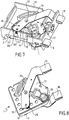
- a first state which will be called “connected state” will be described with reference to the figures 7 and 8 .
- a second state which will be referred to as the “disconnected state” will be described with reference to the figures 9 and 10 .
- the device In its connected state, the device allows the electrical connection between the first electrode 13 of spark gap 4 and the first electrode 10 of varistor 2 by means of the hot-melt solder 3.
- the elastic blade 34 and the helical spring 28 are elastically prestressed.
- the insulator 17 is held elastically in abutment on the body of the spark gap 12 by the spring 29.
- spark gap 4 passes from the state of very high impedance to a state close to short-circuit during the application of a voltage greater than a voltage threshold between the line. electric 5 and the electric line 6.
- this overvoltage induces a current which passes through the varistor 2 and the spark gap 4.
- the current flowing through the varistor 2 and the spark gap 4 then induces a progressive heating of the varistor 2 and of the spark gap 4, and, by conduction , a progressive heating of the hot-melt solder 3 via the thermal bridges 7 and 8.
- the hot-melt solder 3 goes into a liquid state and no longer fixes the varistor 2 and the spark gap 4.
- the insulation between the electric lines 5 and 6 is effective.
- the device In its disconnected state, the device no longer allows the electrical connection between the first electrode 13 of spark gap 4 and the first electrode 10 of varistor 2 because the hot-melt solder 3 is melted.
- connection terminal 15 and the coil spring 28 elastically return to a free state in which they are no longer preloaded. In doing so, the connection terminal 15 drives the spark gap 4 via the fixing member 33, in a direction perpendicular to the plane of the first varistor electrode 10 and in the direction of the distance from the first electrodes. 10 and 13 of spark gap 4 and varistor 2.
- the insulating blade 27 is no longer in abutment on the spark gap body 12 and is inserted between the first electrodes 10 and 13 of spark gap 4 and of varistor 2.
- the insulating blade 27 therefore isolates the first electrodes 10 and 13 d spark gap 4 and varistor 2 from each other.
- the insulating blade 27 thus prevents the appearance of an electric arc between the first spark gap and varistor electrodes.
- the device 1 is able to protect the lines 5 and 6 from fires by completely disconnecting them when the temperature rises beyond a temperature threshold.
- connection terminal 15 is formed of two distinct parts: a flexible strip 134 and a terminal 135 intended to ensure the connection of the device to one of the lines
- the flexible blade 134 and the terminal 135 are fixed to each other by a retaining member 100 formed integrally with the terminal 135.
- the retaining member 100 shown is formed of a folded rectangular metal plate. on a first end of the flexible blade in order to prevent relative movement between the first end of the flexible blade 134 and the terminal 135.
- the retaining member 100 can be a weld made between the flexible blade 134 and the terminal 135.
- a second end 136 of the flexible blade 134 is fixed by a solder or solder to the second spark gap electrode 14.
- the flexible blade 134 is for example made of copper.
- the figure 12 shows the protection device in a housing 191 almost identical to the housing 19.
- a notable difference of this embodiment compared to that shown with reference to figures 1 to 10 is that the return member capable of separating the first varistor 2 and spark gap 4 electrodes when the hot-melt solder 3 is melted is not a helical spring but is here merged with the torsion spring 29 of the 'insulator 17.
- the flexible blade 134 performs the function of electrically connecting the connection terminal 15 with the second spark gap electrode 14.
- the insulator 17 is thus able to exert during the melting of the hot-melt solder 3, on the one hand, the function of electrical insulator between the first electrode 10 of varistor 2 and the first electrode 13 of spark gap 4 and, d 'on the other hand, thanks to the torsion spring 29, the return function capable of separating the first varistor 2 and spark gap 4 electrodes.
- the elastic blade 134 does not have an end cooperating with a helical spring exerting on the elastic blade 134 a force tending to move said end away from the first electrode 10 of the varistor 13.
- the protective device shown in figures 12 and 13 works in particular as described below.
- the insulator 17 has a portion 170 of decreasing thickness having a ramp function ?. In the connected state of the device, the portion 170 of the insulator 17 is resiliently held in abutment against the spark gap body 12 or against the first spark gap electrode 13 by the force of the torsion spring 29.
- the return force of the torsion spring 29 results in a force exerted by the portion 170 of the insulator 17 on the spark gap body 12 or against the first spark gap electrode 13.
- the portion 170 of the insulator is no longer retained by the spark gap body 12 or against the first spark gap electrode 13 and forces the spark gap 4 to move vertically towards the top of the device.
- the portion 170 of the insulator 17 is then inserted between the first electrode 10 of the varistor 2 and the first electrode 13 of the spark gap 4 in order to act as an insulator, or even an arc cutter.
- the second end 136 of the flexible blade 134 is fixed by means of a retaining member 101 to the second spark gap electrode 14.
- This retaining member 101 is an electrically conductive metal plate, also called a thimble, separate from the flexible blade 134 and fixed to the latter by a portion 102 of the holding member 101.
- the portion 102 of the holder 101 is a rectangular metal plate folded over the second end 136 of the flexible blade 134 in order to prevent relative movement between the second end 136 of the flexible blade 134 and the holder 101. .
- the retaining member 101 also has a second portion 103 of circular shape comprising a fixing member 33 for fixing the second spark gap electrode 14 and providing the electrical connection between the flexible blade 134 and the second spark gap electrode 14.
- This fixing member 33 consists of a stamped and perforated portion and a weld made in the stamped portion and passing through the hole to overflow onto the second spark gap electrode 14.
- the embodiment of the device shown in figures 14 and 15 works in the same way as that shown on the figures 12 and 13 regarding the passage of the device from a connected state to a disconnected state.
Landscapes
- Engineering & Computer Science (AREA)
- Microelectronics & Electronic Packaging (AREA)
- Physics & Mathematics (AREA)
- Electromagnetism (AREA)
- Power Engineering (AREA)
- Thermistors And Varistors (AREA)
- Fuses (AREA)
Claims (11)
- Schutzvorrichtung (1) gegen vorübergehende Überspannungen umfassend:- einen Varistor (2), umfassend einen Varistorkörper (9) und eine erste und eine zweite beiderseits des Varistorkörpers angeordnete Elektrode (10, 11), wobei der Varistorkörper (9) einen Temperaturanstieg zeigt, wenn die zwischen den beiden Elektroden (10, 11) angelegte Spannung eine erste Schwelle überschreitet,- eine Funkenstrecke (4), umfassend einen Funkenstreckenkörper und eine erste und eine zweite beiderseits der Funkenstrecke angeordnete Funkenstreckenelektrode (13, 14), wobei durch die Funkenstrecke ein Lichtbogen zwischen den zwei Elektroden herstellbar ist (13, 14) und sich die Funkenstrecke erwärmt, wenn die zwischen den beiden Elektroden (13, 14) angelegte Spannung eine zweite Schwelle überschreitet,- wobei die zweite Elektrode des Varistors (11) verbindbar mit einer ersten elektrischen Leitung (5) und die zweite Elektrode des Varistors (14) verbindbar mit einer zweiten elektrischen Leitung (6) ist, wobei die Schutzvorrichtung dadurch gekennzeichnet ist, dass er umfasst:- eine wärmeschmelzbare Lötstelle (3), welche die erste Elektrode (13) der Funkenstrecke (4) und die erste Elektrode (10) des Varistors befestigt, wobei die wärmeschmelzbare Lötstelle (3) elektrizitätsleitend und über einer Temperaturschwelle schmelzbar ist, wenn sich der Varistor oder die Funkenstrecke erwärmt, und- ein Rückstellorgan (28, 15, 29), welches eine Rückstellkraft ausübt, um die erste Elektrode (10) des Varistors (2) von der ersten Funkenstreckenelektrode (4, 13) beabstandet zu halten, um eine Trennung zwischen der ersten Elektrode (10) des Varistors und der ersten Funkenstreckenelektrode (13) während einer Fusion der wärmeschmelzbaren Lötstelle (3) zu ermöglichen.
- Schutzvorrichtung gemäß Anspruch 1, umfassend weiterhin ein mit der Funkenstrecke verbundenes Kontaktteil (34), wobei das Kontaktteil (34) während der Fusion der schmelzbaren Lötstelle von einer Verbindungsposition, in der die erste Funkenstreckenelektrode (10, 13) und die erste Elektrode des Varistors durch die wärmeschmelzbare Lötstelle (3) angebracht sind, in eine Trennungsposition, in der die erste Funkenstreckenelektrode (10, 13) und die erste Elektrode des Varistors voneinander beabstandet sind, bewegbar ist.
- Schutzvorrichtung gemäß Anspruch 2, wobei das Kontaktteil durch die zweite Elektroden an der Funkenstrecke angebracht und elektrizitätsleitend ist zur Herstellung einer elektrischen Verbindung zwischen der zweiten Funkenstreckenelektrode (14) und der zweiten elektrischen Leitung (6).
- Schutzvorrichtung gemäß Anspruch 2 oder 3, wobei das Kontaktteil von der Verbindungsposition des Kontaktteils (34) zu der Trennungsposition des Kontaktteils bewegbar in einer im Wesentlichen senkrechten Richtung auf einer Ebene der ersten Funkenstreckenelektrode (13) oder der ersten Elektrode des Varistors (10) ist.
- Schutzvorrichtung gemäß einem der Ansprüche 2 bis 4, wobei das Kontaktteil (34) ein elastisches Teil ist, welches in seiner Verbindungsposition vorgespannt ist, so dass es eine Rückstellkraft auf seine Trennungsposition ausübt.
- Schutzvorrichtung gemäß einem der Ansprüche 1 bis 5, umfassend weiterhin einen Isolator, welcher zwischen der ersten Funkenstreckenelektrode (13) und der ersten Elektrode (1) des Varistors einschiebbar ist, während die wärmeschmelzbare Lötstelle (3) schmilzt.
- Schutzvorrichtung gemäß Anspruch 6, wobei das Rückstellorgan eine Feder (29) ist, welche auf den Isolator (17) einwirkt und den Isolator (17) dazu zwingt, während der Fusion der wärmeschmelzbaren Lötstelle (3) die Funkenstrecke (4) zu bewegen und die erste Elektrode (10) des Varistors (2) von der ersten Funkenstreckenelektrode (4, 13) zu beabstanden.
- Schutzvorrichtung gemäß einem der Ansprüche 2 bis 5, wobei das Rückstellorgan eine Feder (28) ist, welche auf das Kontaktteil (34) einwirkt und dazu konfiguriert ist, das Kontaktteil in seine Trennungsposition zurückzustellen.
- Schutzvorrichtung gemäß Anspruch 6 oder 7, wobei der Isolator (17) eine Isolationsfläche (27) umfasst, welche bewegbar von einer nicht eingeschobenen Position zu einer eingeschobenen Position angeordnet ist, wobei die Isolationsfläche unter Wirkung einer durch eine Feder (29) ausgeübten Rückstellkraft zwischen der ersten Elektrode des Varistors und der ersten Funkenstreckenelektrode angeordnet ist.
- Schutzvorrichtung gemäß Anspruch 9, wobei die Isolationsfläche in Rotation zwischen der nicht eingeschobenen Position und der eingeschobenen Position angeordnet ist.
- Schutzvorrichtung gemäß einem der vorstehenden Ansprüche, umfassend weiterhin ein Gehäuse, in welchem der Varistor, die wärmeschmelzbare Lötstelle und die Funkenstrecke und zwei Verbindungsklemmen (15, 16), welche über das Gehäuse überstehen und jeweils mit der zweiten Funkenstreckenelektrode und der zweiten Elektrode des Varistors verbunden sind und jeweils mit der ersten elektrischen Leitung (5) und der zweiten elektrischen Leitung (6) verbindbar sind, angeordnet sind.
Priority Applications (1)
| Application Number | Priority Date | Filing Date | Title |
|---|---|---|---|
| DE17170561.9T DE17170561T1 (de) | 2016-05-12 | 2017-05-11 | Schutzvorrichtung gegen vorübergehende Überspannungen |
Applications Claiming Priority (1)
| Application Number | Priority Date | Filing Date | Title |
|---|---|---|---|
| FR1654243A FR3051292B1 (fr) | 2016-05-12 | 2016-05-12 | Dispositif de protection contre les surtensions transitoires |
Publications (2)
| Publication Number | Publication Date |
|---|---|
| EP3244504A1 EP3244504A1 (de) | 2017-11-15 |
| EP3244504B1 true EP3244504B1 (de) | 2021-08-11 |
Family
ID=57348756
Family Applications (1)
| Application Number | Title | Priority Date | Filing Date |
|---|---|---|---|
| EP17170561.9A Active EP3244504B1 (de) | 2016-05-12 | 2017-05-11 | Schutzvorrichtung gegen vorübergehende überspannungen |
Country Status (6)
| Country | Link |
|---|---|
| US (1) | US10056217B2 (de) |
| EP (1) | EP3244504B1 (de) |
| CN (1) | CN107370140B (de) |
| DE (1) | DE17170561T1 (de) |
| ES (1) | ES2672626T1 (de) |
| FR (1) | FR3051292B1 (de) |
Families Citing this family (7)
| Publication number | Priority date | Publication date | Assignee | Title |
|---|---|---|---|---|
| FR3094148B1 (fr) * | 2019-03-20 | 2021-04-16 | Citel | Dispositif de protection contre les surtensions |
| FR3094147B1 (fr) * | 2019-03-20 | 2023-01-06 | Citel | Dispositif de protection contre les surtensions |
| CN219105843U (zh) * | 2022-04-20 | 2023-05-30 | 厦门赛尔特电子有限公司 | 一种热保护型压敏电阻 |
| US12418175B2 (en) | 2022-09-14 | 2025-09-16 | Ripd Ip Development Ltd | Surge protective devices |
| EP4339990B1 (de) * | 2022-09-14 | 2026-05-06 | RIPD IP Development Ltd | Überspannungsschutzvorrichtungen |
| FR3140489B1 (fr) | 2022-09-29 | 2026-03-06 | Citel | Dispositif de protection contre les surtensions et procédé de fabrication d’un tel dispositif |
| FR3146036B1 (fr) | 2023-02-16 | 2025-02-07 | Citel | Dispositif de protection contre les surtensions |
Family Cites Families (12)
| Publication number | Priority date | Publication date | Assignee | Title |
|---|---|---|---|---|
| FR2766986B1 (fr) * | 1997-08-01 | 1999-10-22 | Soule Materiel Electr | Perfectionnement en dispositif de protection contre les surtensions |
| US6430019B1 (en) * | 1998-06-08 | 2002-08-06 | Ferraz S.A. | Circuit protection device |
| FR2813454B1 (fr) * | 2000-08-29 | 2002-12-06 | Citel | Dispositif de protection contre les surtensions |
| DE20220908U1 (de) * | 2001-12-17 | 2004-07-29 | Phoenix Contact Gmbh & Co. Kg | Überspannungsschutzeinrichtung |
| FR2851369B1 (fr) * | 2003-02-13 | 2008-08-08 | Hager Electro Sas | Ensemble de protection contre les surtensions dues a la foudre |
| FR2871932B1 (fr) * | 2004-06-18 | 2006-08-04 | Schneider Electric Ind Sas | Dispositif de protection contre les surtensions |
| US7483252B2 (en) * | 2006-12-05 | 2009-01-27 | Ferraz Shawmut S.A. | Circuit protection device |
| CN101834434B (zh) * | 2009-07-27 | 2012-05-23 | 佛山市浦斯电子有限公司 | 一种具有热保护装置的电涌保护器 |
| FR2958788B1 (fr) * | 2010-04-09 | 2015-01-30 | Abb France | Varistance comprenant une electrode avec une partie en saillie formant pole et parafoudre comprenant une telle varistance |
| FR2958787B1 (fr) * | 2010-04-09 | 2012-05-11 | Abb France | Dispositif de protection contre les surtensions a deconnecteurs thermiques dedoubles |
| CN102332347B (zh) * | 2010-07-12 | 2013-09-11 | 施耐德电器工业公司 | 过电压保护装置 |
| CN204089185U (zh) * | 2014-06-27 | 2015-01-07 | 菲尼克斯亚太电气(南京)有限公司 | 防浪涌保护器 |
-
2016
- 2016-05-12 FR FR1654243A patent/FR3051292B1/fr not_active Expired - Fee Related
-
2017
- 2017-05-11 EP EP17170561.9A patent/EP3244504B1/de active Active
- 2017-05-11 DE DE17170561.9T patent/DE17170561T1/de active Pending
- 2017-05-11 ES ES17170561.9T patent/ES2672626T1/es active Pending
- 2017-05-11 US US15/592,761 patent/US10056217B2/en active Active
- 2017-05-12 CN CN201710335632.7A patent/CN107370140B/zh active Active
Also Published As
| Publication number | Publication date |
|---|---|
| CN107370140A (zh) | 2017-11-21 |
| FR3051292A1 (fr) | 2017-11-17 |
| US10056217B2 (en) | 2018-08-21 |
| US20170330719A1 (en) | 2017-11-16 |
| DE17170561T1 (de) | 2018-08-09 |
| ES2672626T1 (es) | 2018-06-15 |
| CN107370140B (zh) | 2020-10-09 |
| EP3244504A1 (de) | 2017-11-15 |
| FR3051292B1 (fr) | 2020-09-11 |
Similar Documents
| Publication | Publication Date | Title |
|---|---|---|
| EP3319194B1 (de) | Schutzvorrichtung gegen vorübergehende überspannungen | |
| EP3244504A1 (de) | Schutzvorrichtung gegen vorübergehende überspannungen | |
| EP2375425B1 (de) | Schutzvorrichtung gegen vorübergehende überlastspannung mit verbessertem thermoabschalter | |
| EP2375426B1 (de) | Varistor, der eine Elektrode mit einem vorstehenden Teil umfasst, der einen Kontakt bildet und Blitzableiter, der einen solchen Varistor umfasst | |
| EP2375424B1 (de) | Schutzvorrichtung gegen Überlastspannung mit parallelen Thermoabschaltern | |
| EP3316431B1 (de) | Kapselung eines bauteils, welches einen thermisch geschützten varistor und eine funkenstrecke in serie beeinhaltet | |
| EP1826793B1 (de) | Vorrichtung zum Schutz gegen Überspannungen mit Thermoschalter mit doppelter Kontaktfläche | |
| CA2355485A1 (fr) | Dispositif de protection contre les surtensions | |
| EP1743346B1 (de) | Überspannungsschutzeinrichtung mit lichtbogenlöschelementen | |
| EP1579542A1 (de) | Einrichtung zum schutz vor überspannungen | |
| FR3023988A3 (de) | ||
| FR3094148A1 (fr) | Dispositif de protection contre les surtensions | |
| FR2914108A1 (fr) | Fusible thermique pour boitier electronique et procede d'implantation d'un tel fusible dans un boitier electronique | |
| EP0027061B1 (de) | Blitzableitervorrichtung, welche ein äusserliches Kurzschliessen erlaubt, und entsprechende Schutzeinheit | |
| FR2982705A1 (fr) | Dispositif de protection d'un circuit electrique alimente par un courant alternatif integrable dans un contacteur. | |
| FR3140489A1 (fr) | Dispositif de protection contre les surtensions et procédé de fabrication d’un tel dispositif | |
| FR2877154A1 (fr) | Dispositif perfectionne de protection d'appareils electriques contre des surtensions | |
| EP3185275A1 (de) | Vorrichtung zur montage eines bimetallstreifens und eines teils, das einen träger dieses bimetallstreifens bildet, und elektrische schutzvorrichtung, die eine solche vorrichtung umfasst | |
| EP1698029B1 (de) | Überspannungsschutzvorrichtung mit klemmanordnung | |
| FR2758420A1 (fr) | Dispositif de protection a base de varistance | |
| FR2763438A1 (fr) | Dispositif de protection de ligne a coupure integree | |
| FR2723642A1 (fr) | Dispositif pour detecter et exploiter un courant de foudre circulant sur une ligne electrique | |
| FR2484695A1 (fr) | Parafoudre permettant une mise en court-circuit exterieure | |
| FR2986380A1 (fr) | Dispositif de protection de ligne electrique |
Legal Events
| Date | Code | Title | Description |
|---|---|---|---|
| PUAI | Public reference made under article 153(3) epc to a published international application that has entered the european phase |
Free format text: ORIGINAL CODE: 0009012 |
|
| STAA | Information on the status of an ep patent application or granted ep patent |
Free format text: STATUS: THE APPLICATION HAS BEEN PUBLISHED |
|
| AK | Designated contracting states |
Kind code of ref document: A1 Designated state(s): AL AT BE BG CH CY CZ DE DK EE ES FI FR GB GR HR HU IE IS IT LI LT LU LV MC MK MT NL NO PL PT RO RS SE SI SK SM TR |
|
| AX | Request for extension of the european patent |
Extension state: BA ME |
|
| STAA | Information on the status of an ep patent application or granted ep patent |
Free format text: STATUS: REQUEST FOR EXAMINATION WAS MADE |
|
| REG | Reference to a national code |
Ref country code: ES Ref legal event code: BA2A Ref document number: 2672626 Country of ref document: ES Kind code of ref document: T1 Effective date: 20180615 |
|
| 17P | Request for examination filed |
Effective date: 20180514 |
|
| RBV | Designated contracting states (corrected) |
Designated state(s): AL AT BE BG CH CY CZ DE DK EE ES FI FR GB GR HR HU IE IS IT LI LT LU LV MC MK MT NL NO PL PT RO RS SE SI SK SM TR |
|
| REG | Reference to a national code |
Ref legal event code: R210 Ref country code: DE Ref legal event code: R210 Ref document number: 602017043693 Country of ref document: DE |
|
| GRAP | Despatch of communication of intention to grant a patent |
Free format text: ORIGINAL CODE: EPIDOSNIGR1 |
|
| STAA | Information on the status of an ep patent application or granted ep patent |
Free format text: STATUS: GRANT OF PATENT IS INTENDED |
|
| RIC1 | Information provided on ipc code assigned before grant |
Ipc: H02H 9/06 20060101ALI20210304BHEP Ipc: H02H 9/04 20060101AFI20210304BHEP |
|
| INTG | Intention to grant announced |
Effective date: 20210324 |
|
| GRAS | Grant fee paid |
Free format text: ORIGINAL CODE: EPIDOSNIGR3 |
|
| GRAA | (expected) grant |
Free format text: ORIGINAL CODE: 0009210 |
|
| STAA | Information on the status of an ep patent application or granted ep patent |
Free format text: STATUS: THE PATENT HAS BEEN GRANTED |
|
| REG | Reference to a national code |
Ref country code: DE Ref legal event code: R082 Ref document number: 602017043693 Country of ref document: DE Ref country code: DE Ref legal event code: R082 Ref document number: 602017043693 Country of ref document: DE Representative=s name: GESKES PATENT- UND RECHTSANWAELTE, DE |
|
| AK | Designated contracting states |
Kind code of ref document: B1 Designated state(s): AL AT BE BG CH CY CZ DE DK EE ES FI FR GB GR HR HU IE IS IT LI LT LU LV MC MK MT NL NO PL PT RO RS SE SI SK SM TR |
|
| REG | Reference to a national code |
Ref country code: CH Ref legal event code: EP |
|
| REG | Reference to a national code |
Ref country code: DE Ref legal event code: R082 Ref document number: 602017043693 Country of ref document: DE Representative=s name: GESKES PATENT- UND RECHTSANWAELTE, DE |
|
| REG | Reference to a national code |
Ref country code: DE Ref legal event code: R096 Ref document number: 602017043693 Country of ref document: DE |
|
| REG | Reference to a national code |
Ref country code: IE Ref legal event code: FG4D Free format text: LANGUAGE OF EP DOCUMENT: FRENCH Ref country code: AT Ref legal event code: REF Ref document number: 1420372 Country of ref document: AT Kind code of ref document: T Effective date: 20210915 |
|
| REG | Reference to a national code |
Ref country code: LT Ref legal event code: MG9D |
|
| REG | Reference to a national code |
Ref country code: NL Ref legal event code: MP Effective date: 20210811 |
|
| REG | Reference to a national code |
Ref country code: AT Ref legal event code: MK05 Ref document number: 1420372 Country of ref document: AT Kind code of ref document: T Effective date: 20210811 |
|
| PG25 | Lapsed in a contracting state [announced via postgrant information from national office to epo] |
Ref country code: NO Free format text: LAPSE BECAUSE OF FAILURE TO SUBMIT A TRANSLATION OF THE DESCRIPTION OR TO PAY THE FEE WITHIN THE PRESCRIBED TIME-LIMIT Effective date: 20211111 Ref country code: PT Free format text: LAPSE BECAUSE OF FAILURE TO SUBMIT A TRANSLATION OF THE DESCRIPTION OR TO PAY THE FEE WITHIN THE PRESCRIBED TIME-LIMIT Effective date: 20211213 Ref country code: HR Free format text: LAPSE BECAUSE OF FAILURE TO SUBMIT A TRANSLATION OF THE DESCRIPTION OR TO PAY THE FEE WITHIN THE PRESCRIBED TIME-LIMIT Effective date: 20210811 Ref country code: ES Free format text: LAPSE BECAUSE OF FAILURE TO SUBMIT A TRANSLATION OF THE DESCRIPTION OR TO PAY THE FEE WITHIN THE PRESCRIBED TIME-LIMIT Effective date: 20210811 Ref country code: FI Free format text: LAPSE BECAUSE OF FAILURE TO SUBMIT A TRANSLATION OF THE DESCRIPTION OR TO PAY THE FEE WITHIN THE PRESCRIBED TIME-LIMIT Effective date: 20210811 Ref country code: LT Free format text: LAPSE BECAUSE OF FAILURE TO SUBMIT A TRANSLATION OF THE DESCRIPTION OR TO PAY THE FEE WITHIN THE PRESCRIBED TIME-LIMIT Effective date: 20210811 Ref country code: AT Free format text: LAPSE BECAUSE OF FAILURE TO SUBMIT A TRANSLATION OF THE DESCRIPTION OR TO PAY THE FEE WITHIN THE PRESCRIBED TIME-LIMIT Effective date: 20210811 Ref country code: BG Free format text: LAPSE BECAUSE OF FAILURE TO SUBMIT A TRANSLATION OF THE DESCRIPTION OR TO PAY THE FEE WITHIN THE PRESCRIBED TIME-LIMIT Effective date: 20211111 Ref country code: RS Free format text: LAPSE BECAUSE OF FAILURE TO SUBMIT A TRANSLATION OF THE DESCRIPTION OR TO PAY THE FEE WITHIN THE PRESCRIBED TIME-LIMIT Effective date: 20210811 Ref country code: SE Free format text: LAPSE BECAUSE OF FAILURE TO SUBMIT A TRANSLATION OF THE DESCRIPTION OR TO PAY THE FEE WITHIN THE PRESCRIBED TIME-LIMIT Effective date: 20210811 |
|
| PG25 | Lapsed in a contracting state [announced via postgrant information from national office to epo] |
Ref country code: PL Free format text: LAPSE BECAUSE OF FAILURE TO SUBMIT A TRANSLATION OF THE DESCRIPTION OR TO PAY THE FEE WITHIN THE PRESCRIBED TIME-LIMIT Effective date: 20210811 Ref country code: LV Free format text: LAPSE BECAUSE OF FAILURE TO SUBMIT A TRANSLATION OF THE DESCRIPTION OR TO PAY THE FEE WITHIN THE PRESCRIBED TIME-LIMIT Effective date: 20210811 Ref country code: GR Free format text: LAPSE BECAUSE OF FAILURE TO SUBMIT A TRANSLATION OF THE DESCRIPTION OR TO PAY THE FEE WITHIN THE PRESCRIBED TIME-LIMIT Effective date: 20211112 |
|
| PG25 | Lapsed in a contracting state [announced via postgrant information from national office to epo] |
Ref country code: NL Free format text: LAPSE BECAUSE OF FAILURE TO SUBMIT A TRANSLATION OF THE DESCRIPTION OR TO PAY THE FEE WITHIN THE PRESCRIBED TIME-LIMIT Effective date: 20210811 |
|
| PG25 | Lapsed in a contracting state [announced via postgrant information from national office to epo] |
Ref country code: DK Free format text: LAPSE BECAUSE OF FAILURE TO SUBMIT A TRANSLATION OF THE DESCRIPTION OR TO PAY THE FEE WITHIN THE PRESCRIBED TIME-LIMIT Effective date: 20210811 |
|
| REG | Reference to a national code |
Ref country code: DE Ref legal event code: R097 Ref document number: 602017043693 Country of ref document: DE |
|
| PG25 | Lapsed in a contracting state [announced via postgrant information from national office to epo] |
Ref country code: SM Free format text: LAPSE BECAUSE OF FAILURE TO SUBMIT A TRANSLATION OF THE DESCRIPTION OR TO PAY THE FEE WITHIN THE PRESCRIBED TIME-LIMIT Effective date: 20210811 Ref country code: SK Free format text: LAPSE BECAUSE OF FAILURE TO SUBMIT A TRANSLATION OF THE DESCRIPTION OR TO PAY THE FEE WITHIN THE PRESCRIBED TIME-LIMIT Effective date: 20210811 Ref country code: RO Free format text: LAPSE BECAUSE OF FAILURE TO SUBMIT A TRANSLATION OF THE DESCRIPTION OR TO PAY THE FEE WITHIN THE PRESCRIBED TIME-LIMIT Effective date: 20210811 Ref country code: EE Free format text: LAPSE BECAUSE OF FAILURE TO SUBMIT A TRANSLATION OF THE DESCRIPTION OR TO PAY THE FEE WITHIN THE PRESCRIBED TIME-LIMIT Effective date: 20210811 Ref country code: CZ Free format text: LAPSE BECAUSE OF FAILURE TO SUBMIT A TRANSLATION OF THE DESCRIPTION OR TO PAY THE FEE WITHIN THE PRESCRIBED TIME-LIMIT Effective date: 20210811 Ref country code: AL Free format text: LAPSE BECAUSE OF FAILURE TO SUBMIT A TRANSLATION OF THE DESCRIPTION OR TO PAY THE FEE WITHIN THE PRESCRIBED TIME-LIMIT Effective date: 20210811 |
|
| PLBE | No opposition filed within time limit |
Free format text: ORIGINAL CODE: 0009261 |
|
| STAA | Information on the status of an ep patent application or granted ep patent |
Free format text: STATUS: NO OPPOSITION FILED WITHIN TIME LIMIT |
|
| 26N | No opposition filed |
Effective date: 20220512 |
|
| PG25 | Lapsed in a contracting state [announced via postgrant information from national office to epo] |
Ref country code: IT Free format text: LAPSE BECAUSE OF FAILURE TO SUBMIT A TRANSLATION OF THE DESCRIPTION OR TO PAY THE FEE WITHIN THE PRESCRIBED TIME-LIMIT Effective date: 20210811 |
|
| PG25 | Lapsed in a contracting state [announced via postgrant information from national office to epo] |
Ref country code: SI Free format text: LAPSE BECAUSE OF FAILURE TO SUBMIT A TRANSLATION OF THE DESCRIPTION OR TO PAY THE FEE WITHIN THE PRESCRIBED TIME-LIMIT Effective date: 20210811 |
|
| REG | Reference to a national code |
Ref country code: CH Ref legal event code: PL |
|
| REG | Reference to a national code |
Ref country code: BE Ref legal event code: MM Effective date: 20220531 |
|
| GBPC | Gb: european patent ceased through non-payment of renewal fee |
Effective date: 20220511 |
|
| PG25 | Lapsed in a contracting state [announced via postgrant information from national office to epo] |
Ref country code: MC Free format text: LAPSE BECAUSE OF FAILURE TO SUBMIT A TRANSLATION OF THE DESCRIPTION OR TO PAY THE FEE WITHIN THE PRESCRIBED TIME-LIMIT Effective date: 20210811 Ref country code: LU Free format text: LAPSE BECAUSE OF NON-PAYMENT OF DUE FEES Effective date: 20220511 Ref country code: LI Free format text: LAPSE BECAUSE OF NON-PAYMENT OF DUE FEES Effective date: 20220531 Ref country code: CH Free format text: LAPSE BECAUSE OF NON-PAYMENT OF DUE FEES Effective date: 20220531 |
|
| PG25 | Lapsed in a contracting state [announced via postgrant information from national office to epo] |
Ref country code: IE Free format text: LAPSE BECAUSE OF NON-PAYMENT OF DUE FEES Effective date: 20220511 |
|
| PG25 | Lapsed in a contracting state [announced via postgrant information from national office to epo] |
Ref country code: GB Free format text: LAPSE BECAUSE OF NON-PAYMENT OF DUE FEES Effective date: 20220511 Ref country code: BE Free format text: LAPSE BECAUSE OF NON-PAYMENT OF DUE FEES Effective date: 20220531 |
|
| PG25 | Lapsed in a contracting state [announced via postgrant information from national office to epo] |
Ref country code: HU Free format text: LAPSE BECAUSE OF FAILURE TO SUBMIT A TRANSLATION OF THE DESCRIPTION OR TO PAY THE FEE WITHIN THE PRESCRIBED TIME-LIMIT; INVALID AB INITIO Effective date: 20170511 |
|
| REG | Reference to a national code |
Ref country code: DE Ref legal event code: R081 Ref document number: 602017043693 Country of ref document: DE Owner name: CITEL S.A.S., FR Free format text: FORMER OWNER: CITEL, SEVRES, FR |
|
| PG25 | Lapsed in a contracting state [announced via postgrant information from national office to epo] |
Ref country code: MK Free format text: LAPSE BECAUSE OF FAILURE TO SUBMIT A TRANSLATION OF THE DESCRIPTION OR TO PAY THE FEE WITHIN THE PRESCRIBED TIME-LIMIT Effective date: 20210811 Ref country code: CY Free format text: LAPSE BECAUSE OF FAILURE TO SUBMIT A TRANSLATION OF THE DESCRIPTION OR TO PAY THE FEE WITHIN THE PRESCRIBED TIME-LIMIT Effective date: 20210811 |
|
| PG25 | Lapsed in a contracting state [announced via postgrant information from national office to epo] |
Ref country code: TR Free format text: LAPSE BECAUSE OF FAILURE TO SUBMIT A TRANSLATION OF THE DESCRIPTION OR TO PAY THE FEE WITHIN THE PRESCRIBED TIME-LIMIT Effective date: 20210811 |
|
| PG25 | Lapsed in a contracting state [announced via postgrant information from national office to epo] |
Ref country code: MT Free format text: LAPSE BECAUSE OF FAILURE TO SUBMIT A TRANSLATION OF THE DESCRIPTION OR TO PAY THE FEE WITHIN THE PRESCRIBED TIME-LIMIT Effective date: 20210811 |
|
| PGFP | Annual fee paid to national office [announced via postgrant information from national office to epo] |
Ref country code: DE Payment date: 20260513 Year of fee payment: 10 |
|
| PGFP | Annual fee paid to national office [announced via postgrant information from national office to epo] |
Ref country code: FR Payment date: 20260528 Year of fee payment: 10 |