EP3244520B1 - Dämpfung von schwingungen in einem filter eines elektrischen antriebssystems - Google Patents
Dämpfung von schwingungen in einem filter eines elektrischen antriebssystems Download PDFInfo
- Publication number
- EP3244520B1 EP3244520B1 EP17168370.9A EP17168370A EP3244520B1 EP 3244520 B1 EP3244520 B1 EP 3244520B1 EP 17168370 A EP17168370 A EP 17168370A EP 3244520 B1 EP3244520 B1 EP 3244520B1
- Authority
- EP
- European Patent Office
- Prior art keywords
- damping
- filter
- switch
- power conversion
- conversion system
- Prior art date
- Legal status (The legal status is an assumption and is not a legal conclusion. Google has not performed a legal analysis and makes no representation as to the accuracy of the status listed.)
- Active
Links
Images






Classifications
-
- H—ELECTRICITY
- H02—GENERATION; CONVERSION OR DISTRIBUTION OF ELECTRIC POWER
- H02M—APPARATUS FOR CONVERSION BETWEEN AC AND AC, BETWEEN AC AND DC, OR BETWEEN DC AND DC, AND FOR USE WITH MAINS OR SIMILAR POWER SUPPLY SYSTEMS; CONVERSION OF DC OR AC INPUT POWER INTO SURGE OUTPUT POWER; CONTROL OR REGULATION THEREOF
- H02M3/00—Conversion of DC power input into DC power output
- H02M3/22—Conversion of DC power input into DC power output with intermediate conversion into AC
- H02M3/24—Conversion of DC power input into DC power output with intermediate conversion into AC by static converters
-
- H—ELECTRICITY
- H02—GENERATION; CONVERSION OR DISTRIBUTION OF ELECTRIC POWER
- H02M—APPARATUS FOR CONVERSION BETWEEN AC AND AC, BETWEEN AC AND DC, OR BETWEEN DC AND DC, AND FOR USE WITH MAINS OR SIMILAR POWER SUPPLY SYSTEMS; CONVERSION OF DC OR AC INPUT POWER INTO SURGE OUTPUT POWER; CONTROL OR REGULATION THEREOF
- H02M1/00—Details of apparatus for conversion
- H02M1/12—Arrangements for reducing harmonics from AC input or output
-
- H—ELECTRICITY
- H02—GENERATION; CONVERSION OR DISTRIBUTION OF ELECTRIC POWER
- H02M—APPARATUS FOR CONVERSION BETWEEN AC AND AC, BETWEEN AC AND DC, OR BETWEEN DC AND DC, AND FOR USE WITH MAINS OR SIMILAR POWER SUPPLY SYSTEMS; CONVERSION OF DC OR AC INPUT POWER INTO SURGE OUTPUT POWER; CONTROL OR REGULATION THEREOF
- H02M1/00—Details of apparatus for conversion
- H02M1/36—Means for starting or stopping converters
-
- H—ELECTRICITY
- H02—GENERATION; CONVERSION OR DISTRIBUTION OF ELECTRIC POWER
- H02M—APPARATUS FOR CONVERSION BETWEEN AC AND AC, BETWEEN AC AND DC, OR BETWEEN DC AND DC, AND FOR USE WITH MAINS OR SIMILAR POWER SUPPLY SYSTEMS; CONVERSION OF DC OR AC INPUT POWER INTO SURGE OUTPUT POWER; CONTROL OR REGULATION THEREOF
- H02M5/00—Conversion of AC power input into AC power output, e.g. for change of voltage, for change of frequency, for change of number of phases
- H02M5/40—Conversion of AC power input into AC power output, e.g. for change of voltage, for change of frequency, for change of number of phases with intermediate conversion into DC
Definitions
- DE 27 04 112 A1 discloses a circuit that has a capacitive voltage divider, an inductor, an intermediate transformer and a damping load divided into several sections. At least one section of the damping load switched by a switch consists of at least one temperature sensitive resistor with a series impedance. Four-terminal networks may be provided, which hold the damping load connected until at least the temperature sensitive resistor has reached a specified resistance owing to its heating by the power dissipated in it.
- the present invention provides a damping circuit to control damping of a filter circuit of a power conversion system according to claim 1, and a method to automatically control damping of a filter circuit of a power conversion system according to claim 12.
- Preferred embodiments are defined in the dependent claims.
- the present disclosure provides power conversion systems, damping circuits and methods to selectively damp oscillations and/or transients of an input filter using a secondary winding magnetically coupled with a filter inductor winding in a series circuit with a damping resistor and a switch.
- FIG. 1 shows a power system 100 including a three-phase AC power source 102 providing AC input power along phase lines A, B and C to a motor drive power conversion system 110 to drive a motor load 104.
- the power conversion system 110 includes a three-phase input filter circuit 112 that delivers AC power along lines U, V and W to the input of a three-phase active front end (AFE) rectifier 114.
- the filter circuit 112 includes active damping circuitry 118, and the drive 110 includes a damping control circuit or controller 120.
- the rectifier 114 has an input to receive AC input power along the lines U, V and W, as well as an output to provide a DC output signal.
- An intermediate DC circuit, or DC bus is connected to the DC output of the rectifier 114, and in one example includes a capacitor CDC connected between positive and negative DC bus lines.
- FIG. 3 shows a current source converter implementation of the motor drive 110, including one or more DC link chokes or inductors LDC in the intermediate circuit between the output of the rectifier 114 and the input of an inverter 116.
- the inverter 116 in FIGs. 1 and 3 includes an input coupled to the output of the rectifier 114 through the intermediate circuit, and an output coupleable to the motor load 104 to provide an AC output signal.
- the inverter 116 provides a three-phase output signal to drive the motor load 104.
- a single phase AC output signal can be provided by the output of the inverter to drive a load.
- the power conversion system 110 can use a variety of different input filter topologies or configurations 112.
- an inductor - capacitor (LC) or inductor - capacitor - inductor (LCL) input filter circuitry can be associated with each AC input phase to control the harmonic content of a connected power grid.
- LCL or LC filters may be used in voltage source converters, such as the motor drive 110 of FIG. 1 , and LC filters are often used with current source converters as shown in FIG. 3 .
- Such filter circuits are subject to damage or degradation of the filter capacitors, such as by voltage surges or other transients. Filter capacitor degradation, in turn, may be costly in terms of replacement component costs, labor for inspection and replacement, as well as downtime for the power conversion system and any associated machinery.
- filter capacitors may be degraded by oscillation or resonance and/or transient voltages seen by the filter circuit 112.
- oscillation and/or resonance conditions in the motor drive 110 can lead to damage or degradation of one or more components of the AFE rectifier circuit 114 and/or a DC bus capacitor CDC ( FIG. 1 ).
- the present disclosure provides damping circuitry 118 and damping controllers 120 to selectively damp the filter circuit 112 either proactively (e.g., at system startup) and/or in response to one or more detected conditions in the power conversion system 110 as detailed further below.
- FIG. 2 shows a single phase portion of the filter circuit 112.
- the filter circuit 112 in one example is an LC filter with a filter inductor LP and a capacitor C. Similar LC filters are provided for each of the filter input and output connections A/U, B/V, C/W in the system 110 of FIG. 1 .
- the filter inductor LP is connected between a filter input line 201 and a rectifier side filter output line 202, and conducts a first current I1 between the AC input (labeled as GRID SIDE in FIG. 2 ) and the rectifier 114 (RECTIFIER SIDE in FIG. 2 ).
- the secondary winding LS includes a secondary winding LS wound on a common core 204 with the filter inductor LP the, where LP and LS form a transformer with the filter inductor LP forming a primary winding.
- the secondary winding LS is magnetically coupled with the filter inductor LP to conduct a second current I2 induced by flow of the first current I1 through the filter inductor LP.
- the secondary winding is connected in a series circuit with a damping resistor R and a switch S. Any suitable switch can be used, such as a thyristor or other semiconductor-based switch operable according to a damping control signal DCS from the damping control circuit 120.
- the switch S is closed when the DCS signal is in a first state to allow flow of the second current I2 through the damping resistor R.
- the damping control signal DCS is in a different second state, the switch S is opened to prevent the second current 12 from flowing through the damping resistor R.
- the damping controller 120 provides the DCS signal to the switch S to control damping of the filter 112.
- the disclosed examples can use low voltage components including the resistor R and the switch S to effectively combat transients and unwanted resonant conditions in the motor drive 110.
- the damping circuitry 118 can be constructed using low voltage components which are cost-effective and do not occupy large amounts of volume within an enclosure of the motor drive system 110.
- closure of the switch S allows the second current I2 to flow in the damping resistor R, thus presenting increased impedance to the grid side of the filter circuit 112.
- This added impedance can be advantageously employed to control or mitigate (e.g., damp) oscillations or transient events in the motor drive power conversion system 110.
- transient conditions in the AC input power can occur when the conversion system 110 is started up, such as by closing an input contactor or breaker (not shown) to apply AC input power to the drive 110.
- transients or oscillations can occur on the grid side based on load changes elsewhere in the grid, such as a different motor drive turning on or off.
- the filter circuit 112 may implement a low pass filter function with a cutoff frequency set above the fundamental frequency of the AC input source 102, and the filter circuit 112 may undergo resonance at one or more harmonics of the AC input frequency (e.g., fifth harmonic resonance).
- resonance and/or extreme transient voltage conditions associated with the input filter circuit 112 can degrade components of the filter circuit 112 including the filter capacitor C, the active front end rectifier 114 and/or the DC capacitor CDC in certain conditions.
- Selective application of damping by the controller 120 can be used to mitigate or eliminate such harmonic resonance by engaging the active damping circuit 118.
- the controller 120 in certain examples provides the damping control signal DCS to the switch S of the individual active damping circuits 118 to turn on the associated switch S and thereby implement active damping in a continuous fashion.
- the controller 120 provides the DCS signal as an alternating pulse width modulated signal with controlled on-time in order to control damping of the filter circuit 112.
- the controller 120 can initiate such continuous on-time or pulse width modulation damping control (e.g., duty cycle control) according to any suitable open loop or closed loop control configuration.
- the controller 120 in one example controls or regulates the on-time of the damping circuit switch S according to a detected oscillation or transient condition in the power conversion system 110.
- the controller 120 receives sensor information from one or more system sensors (not shown) indicating transients in the DC link or intermediate circuit, such as transient voltage rises on the DC link capacitor CDC, and in response, selectively controls an on-time of the switch S by providing a pulse width modulated DCS signal.
- the on-time of the signal DCS is regulated in one example according to a magnitude of a detected voltage rise on the DC link capacitor CDC.
- the controller 120 responsively provides a pulse width modulated or continuous on-time damping control signal DCS to turn on the damping switch S based on detected resonance in the system 110.
- the controller 120 further monitors one or more system conditions and discontinues active damping operation once a detected transient or resonance condition has been remedied. In this fashion, the controller 120 and the damping circuitry 118 provide active damping on demand capabilities to selectively employ damping when needed. Also, as further described below in connection with FIG. 4 , the controller 120 may provide automatic damping activation at system turn on in certain embodiments.
- the controller 120 advantageously activates the damping circuit 118 by turning on the associated switch S continuously or with a pulse width modulation controlled on-time at startup of the power conversion system 120.
- damping is employed to mitigate the onset of resonance as the filter circuit 112 is initially energized.
- This damping moreover, can also mitigate the likelihood that other circuits and systems connected to the power source 102 (e.g., supply grid) will be subjected to transients or resonance conditions when the power conversion system 110 is started.
- a method or process 400 is illustrated for automatically controlling damping of a filter circuit 112 of the power conversion system 110.
- the illustrated method 400 can be implemented, for example, by the damping control circuit 120 in the motor drive 110 of FIG. 1 or FIG. 3 .
- the drive is turned on at 402 in FIG. 4 , for example, using a contactor or circuit breaker (not shown) between the AC input source 102 and the input filter circuit 112.
- the controller 120 activates the damping circuit 118, either fully on or using duty cycle control via a pulse width modulated control signal DCS to control an on-time during which the damping circuit switch S is turned on.
- the controller 120 can activate the active damping circuit 118 prior to, contemporaneous with, or sometime after, startup of the motor drive 110. Each of these conditions is considered to be "at startup" of the power conversion system 110 is used herein. This operation with the damping circuit activated at 404 may continue in one example for a predetermined time sufficient to ensure that the filter circuit 112 and the host motor drive system 110 will not undergo resonance or unwanted transient conditions based on energization of the filter circuit 112.
- the controller 120 deactivates the damping circuits 118, for example, by placing the associated DCS signals in the second state to turn off the associated damping circuit switches S.
- the power conversion system 110 undergoes various startup procedures (e.g., precharging of the DC link capacitor CDC in the example of FIG. 1 ), and assumes normal drive operation at 408.
- the controller 120 determines whether a transient or oscillation condition has been detected in the system 110. If not (NO at 410), the normal drive operation continues. Once a transient or oscillation condition has been detected in the system 110 (YES at 410), the controller 120 activates the damping circuitry 118 using full on or duty cycle control at 412.
- the controller 120 provides active damping on demand in a responsive manner to accommodate changing conditions in the motor drive 110 and/or the grid side AC power source 102.
- the controller 120 makes a further determination at 414 as to whether the transient or oscillation condition remains. If so (YES at 414), operation continues with the damping circuits 118 activated. Otherwise, if the transient or oscillation condition has subsided (NO at 414), the process 400 returns to deactivate the damping circuits 118 at 406 and normal drive operation is resumed at 408.
- FIGs. 5-12 various example three-phase filter circuits and associated active damping circuits 118 are illustrated. These examples are non-limiting, and other single or multiphase examples can be used in a given system, in which a filter inductor and an associated secondary winding provide a transformer with a switch selectable damping resistance in a secondary circuit.
- FIG. 5 shows an example LC filter circuit 112 in which the filter capacitors CA, CB and CC are connected in a "Y" configuration with a filter neutral N.
- a first filter inductor LPA is connected between a first input phase line 201A (A) and a first rectifier input line 202A (U), and the filter capacitor CA is connected between the line 202A and the neutral N.
- An active damping circuit 118A is associated with the filter inductor LPA, including a secondary winding LSA wound on a common core with a winding of the inductor LPA, as well as a first damping resistor RA and a switch SA operated according to a damping control signal DCSA from the damping control circuit 120.
- the filter circuit 112 in this example further includes a second filter inductor LPAB connected between lines 201B (B) and 202B (V), with the filter capacitor CB connected between the line 202B and the neutral N.
- a second active damping circuit 118B is provided, including a secondary winding LSB magnetically coupled with the second filter inductor LPB via winding around a common core, and the secondary winding LSB is in a series circuit with a second damping resistor RB and a second switch SB operated according to a control signal DCSB.
- the filter circuit 112 also includes a third inductor LPC connected between the grid side line 201C (C) and the rectifier side line 202C (W), with the filter capacitor CC connected between the line 202C and the neutral N.
- a third active damping circuit 118C includes a secondary winding LSC magnetically coupled with the inductor LPC, and the secondary winding LSC is in a series circuit with a third damping resistor RC and a third switch SC operated according to a control signal DCSC from the controller 120.
- FIG. 6 shows another example three-phase LC implementation of the filter circuit 112 and the damping control circuitry 118, similar in most respects to the example of FIG. 5 .
- the controller 120 operates as described above in connection with FIGs. 1-4 in order to provide continuous on-time and/or pulse width modulated control of the individual damping circuits 118 in the systems 110 of FIGs. 5 and 6 via signals DCS in a proactive manner (e.g., on system startup) and/or in response to one or more detected conditions, such as detected transient and/or oscillation conditions in the system 110.
- the controller 120 may, but need not, synchronize the respective damping control signals DCSA, DCSB and DCSC with one another.
- FIGs. 7 and 8 respectively show Y and Delta-connected LCL filter circuits 112 and associated damping circuitry 118 which can be used in the systems 110 of FIGs. 1 and/or 3 above.
- the first phase line of the filter circuit 112 (e.g., from A to U) includes a first filter inductor LPA-1 with an associated low-voltage damping circuit 118A, and a second filter inductor LA-2 connected between an intermediate node 203A and the rectifier side line 202A.
- the B/V and C/W phases include first filter inductors LPB-1 and LPC-1 as well as second filter inductors LB-2 and LC-2 connected between the intermediate nodes 203B, 203C and the rectifier side lines 202B and 202C as shown in FIG. 7 .
- the B/V and C/W phases also include damping circuits 118B and 118C providing secondary circuits to the first filter inductors LPB-1 and LPC-1, respectively.
- the filter capacitor CA is connected between the line 203A and the neutral N
- capacitor CB is connected between the line 203B and the neutral N
- the capacitor CC is connected between the line 203C and the neutral N.
- FIG. 8 illustrates a Delta filter circuit example 112, in which the filter capacitors CAB, CBC, and CCA are interconnected in a Delta configuration.
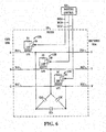
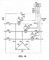
- FIGs. 9 and 10 respectively show Y and Delta-connected LCL filter circuits 112 along with associated damping circuitry 118A, 118B and 118C.
- the damping circuitry 118 in FIGs. 9 and 10 are individually associated with the second filter inductors on the rectifier side of the filter circuit 112.
- the A/U phase of the filter 112 includes a first filter inductor LA-1 and a second filter inductor LPA-2 connected between the intermediate node 203A and the rectifier side output line 202A, with an associated secondary circuit providing a damping circuit 118A.
- the B/V and C/W phases include first filter inductors LPB-1 and LPC-1 as well as second filter inductors LB-2 and LC-2 connected between the intermediate nodes 203B, 203C and the rectifier side lines 202B and 202C as shown in FIG. 7 .
- the filter capacitors CA, CB and CC are connected in a Y configuration with a neutral connection N, whereas the filter capacitors CAB, CBC and CCA are connected in a Delta configuration in the filter 112 of FIG. 10 .
- FIGs. 11 and 12 illustrate further example LCL filters 112, each including first filter inductors LPA-1, LPB-1 and LPC-1 as well as second filter inductors LPA-2, LPB-2 and LPC-2.
- damping circuits 118 are individually associated with each of the first and second filter inductors.
- the first phase includes a first damping circuit 118A-1 including a secondary winding LSA-1, a damping resistor RA-1 and a switch SA-1 operated according to a control signal DCSA-1, as well as a second damping circuit 118A-2 including a secondary winding LSA-2, a damping resistor RA-2 and a switch SA-2 operated according to a damping control signal DCSA-2.
- the second phase includes a first damping circuit 118B-1 with a secondary winding LSB-1, a damping resistor RB-1 and a switch SB-1 operated according to a control signal DCSB-1, and a second damping circuit 118B-2 including a secondary winding LSB-2, a damping resistor RB-2 and a switch SB-2 operated according to a damping control signal DCSB-2.
- the third phase includes a first damping circuit 118C-1 with a secondary winding LSC-1 magnetically coupled with the inductor LPC-1, a damping resistor RC-1 and a switch SC-1 operated according to a control signal DCSC-1, and a second damping circuit 118C-2 including a secondary winding LSC-2 magnetically coupled with the filter inductor LPC-2, a damping resistor RC-2 and a switch SC-2 operated according to a damping control signal DCSC-2.
- the filter 112 of FIG. 11 includes filter capacitors CA, CB and CC connected in a Y configuration with a neutral connection N. In the filter 112 of FIG. 12 , the filter capacitors CAB, CBC and CCA are connected in a Delta configuration.
Landscapes
- Engineering & Computer Science (AREA)
- Power Engineering (AREA)
- Inverter Devices (AREA)
- Power Conversion In General (AREA)
Claims (15)
- Dämpfungsschaltung zum Steuern der Dämpfung einer Filterschaltung eines Leistungsumwandlungssystems, wobei die Dämpfungsschaltung umfasst:
einen Transformator, der beinhaltet:eine Primärwicklung (LP), die um einen Kern (204) gewickelt ist, um einen ersten Strom (I1) zu leiten, der in einer Filterschaltung (112) zwischen einem Wechselstromeingang und einem Gleichrichter (114) eines Leistungsumwandlungssystems (110) fließt,einen Sekundärwicklung (LS), die um den Kern (204) gewickelt ist, um einen zweiten Strom (I2) zu leiten, der dadurch induziert wird, dass Strom (I1) in der Primärwicklung (LP) fließt,einen Dämpfungswiderstand (R), undeinen Schalter (S), der in einer Reihenschaltung mit der Sekundärwicklung (LS) und dem Dämpfungswiderstand (R) verbunden ist; undeine Steuerung (120), die dazu konfiguriert ist, den Schalter (S) selektiv zu schließen, um die Dämpfung der Filterschaltung (120) zu steuern. - Dämpfungsschaltung nach Anspruch 1, wobei die Steuerung zu Folgendem konfiguriert ist:Steuern einer Einschaltzeit des Schalters, um die Dämpfung der Filterschaltung zu steuern; und/oderselektives Schließen des Schalters als Reaktion auf eine ermittelte Oszillation oder Transiente in dem Leistungsumwandlungssystem.
- Leistungsumwandlungssystem (110), umfassend die Dämpfungsschaltung nach Anspruch 1, wobei das Leistungsumwandlungssystem (110) umfasst:einen Wechselstromeingang (102), der mit einer Stromquelle (102) gekoppelt und dazu konfiguriert ist, eine Wechselstromeingangsleistung von der Stromquelle (102) zu empfangen;einen Gleichrichter (114) mit einem Eingang, der dazu konfiguriert ist, eine Wechselstromeingangsleistung zu empfangen, und einem Ausgang, der dazu konfiguriert ist, ein Gleichstromausgangssignal bereitzustellen;einen Wechselrichter (116) mit einem Eingang, der mit dem Ausgang des Gleichrichters (114) verbunden ist, und einem Ausgang, der mit einer Last (104) verbunden ist, wobei der Ausgang dazu konfiguriert ist, ein Wechselstromausgangssignal bereitzustellen; unddie Filterschaltung (20), die zwischen dem Wechselstromeingang und dem Gleichrichter (114) gekoppelt ist, wobei die Filterschaltung (112) beinhaltet:eine Filterdrosselspule (LP), welche die Primärwicklung (LP) bildet, undeinen Filterkondensator (C), der mit der Filterdrosselspule (LP) gekoppelt ist,wobei der Schalter (S) dazu konfiguriert ist, in Funktion, wenn sich ein Dämpfungssteuersignal in einem ersten Zustand befindet, zuzulassen, dass der zweite Strom (12) durch den Dämpfungswiderstand (R) fließt, und der Schalter (S) dazu konfiguriert ist, in Funktion, wenn sich das Dämpfungssteuersignal in einem zweiten Zustand befindet, zu verhindern, dass der zweite Strom (12) durch den Dämpfungswiderstand (R) fließt.
- Leistungsumwandlungssystem (110) nach Anspruch 3, wobei die Steuerung dazu konfiguriert ist, in Funktion das Dämpfungssteuersignal für den Schalter als ein alternierendes pulsbreitenmoduliertes Signal bereitzustellen, um die Dämpfung der Filterschaltung zu steuern.
- Leistungsumwandlungssystem (110) nach Anspruch 4, wobei die Steuerung dazu konfiguriert ist, in Funktion selektiv eine Einschaltzeit des Schalters zu steuern, wenn sich das alternierende pulsbreitenmodulierte Dämpfungssteuersignal in dem ersten Zustand befindet, als Reaktion auf eine ermittelte Oszillation oder Transiente in dem Leistungsumwandlungssystem.
- Leistungsumwandlungssystem (110) nach Anspruch 4 oder 5, wobei die Steuerung dazu konfiguriert ist, in Funktion selektiv eine Einschaltzeit des Schalters zu steuern, wenn sich das alternierende pulsbreitenmodulierte Dämpfungssteuersignal beim Hochfahren des Leistungsumwandlungssystems in dem ersten Zustand befindet.
- Leistungsumwandlungssystem nach einem der Ansprüche 3 bis 6, wobei die Filterschaltung ein LC-Filter ist und wobei die Filterdrosselspule zwischen dem Wechselstromeingang und dem Gleichrichter gekoppelt ist.
- Leistungsumwandlungssystem nach einem der Ansprüche 3 bis 6, wobei die Filterschaltung ein LCL-Filter mit einer zweiten Filterdrosselspule ist, die in Reihe mit der Filterdrosselspule zwischen dem Wechselstromeingang und dem Gleichrichter gekoppelt ist.
- Leistungsumwandlungssystem nach einem der Ansprüche 3 bis 8, wobei die Steuerung dazu konfiguriert ist, in Funktion das Dämpfungssteuersignal in den ersten Zustand beim Hochfahren des Leistungsumwandlungssystems bereitzustellen.
- Leistungsumwandlungssystem nach einem der Ansprüche 8 bis 9, wobei die Dämpfungsschaltung beinhaltet:eine weitere Sekundärwicklung, die magnetisch mit der zweiten Filterdrosselspule gekoppelt und dazu konfiguriert ist, einen dritten Strom zu leiten, der dadurch induziert wird, dass Strom in der zweiten Filterdrosselspule fließt,einen zweiten Dämpfungswiderstand, undeinen zweiten Schalter, der in einer Reihenschaltung mit der weiteren Sekundärwicklung und dem zweiten Dämpfungswiderstand gekoppelt ist, wobei der zweite Schalter in Funktion, wenn sich ein zweites Dämpfungssteuersignal in dem ersten Zustand befindet, zulässt, dass der dritte Strom durch den zweiten Dämpfungswiderstand fließt, und der zweite Schalter dazu konfiguriert ist, in Funktion, wenn sich das zweite Dämpfungssteuersignal in einem zweiten Zustand befindet, zu verhindern, dass der dritte Strom durch den zweiten Dämpfungswiderstand fließt; undwobei die Steuerung dazu konfiguriert ist, in Funktion das zweite Dämpfungssteuersignal an den zweiten Schalter bereitzustellen, um die Dämpfung der Filterschaltung zu steuern.
- Leistungswandlungssystem nach einem der Ansprüche 3 bis 10, wobei die Sekundärwicklung und die Filterdrosselspule auf einen gemeinsamen Kern gewickelt sind.
- Verfahren (400) zum automatischen Steuern der Dämpfung einer Filterschaltung (112) eines Leistungsumwandlungssystems (110), wobei das Verfahren (400) umfasst:Bereitstellen eines Dämpfungswiderstands (R) und eines Schalters (S) in einer Reihenschaltung mit einer Sekundärwicklung (LS), die magnetisch mit einer Filterdrosselspule (LP) einer Filterschaltung (112) des Leistungsumwandlungssystems (110) gekoppelt ist, um einen zweiten Strom (12) zu leiten, der durch einen ersten Strom (11) induziert wird, der in der Filterdrosselspule (LP) fließt, wobei die Filterdrosselspule (LP) den ersten Strom (11) leitet, der in der Filterschaltung (112) zwischen einem Wechselstromeingang und einem Gleichrichter fließt;selektives Einschalten des Schalters, damit der zweite Strom in dem Dämpfungswiderstand fließen kann, um die Dämpfung der Filterschaltung zu steuern.
- Verfahren nach Anspruch 12, des Weiteren umfassend das Steuern einer Einschaltzeit des Schalters, um die Dämpfung der Filterschaltung zu steuern.
- Verfahren nach Anspruch 12, des Weiteren umfassend das selektive Einschalten des Schalters als Reaktion auf eine ermittelte Oszillation oder Transiente in dem Leistungsumwandlungssystem, und
des Weiteren umfassend das Steuern einer Einschaltzeit des Schalters, um die Dämpfung der Filterschaltung als Reaktion auf die ermittelte Oszillation oder Transiente in dem Leistungsumwandlungssystem zu steuern. - Verfahren nach Anspruch 12, des Weiteren umfassend das Einschalten des Schalters beim Hochfahren des Leistungsumwandlungssystems, und
des Weiteren umfassend das Steuern einer Einschaltzeit des Schalters, um die Dämpfung der Filterschaltung beim Hochfahren des Leistungsumwandlungssystems zu steuern.
Applications Claiming Priority (1)
| Application Number | Priority Date | Filing Date | Title |
|---|---|---|---|
| US15/149,384 US9923469B2 (en) | 2016-05-09 | 2016-05-09 | Motor drive filter damping |
Publications (2)
| Publication Number | Publication Date |
|---|---|
| EP3244520A1 EP3244520A1 (de) | 2017-11-15 |
| EP3244520B1 true EP3244520B1 (de) | 2021-08-18 |
Family
ID=58701402
Family Applications (1)
| Application Number | Title | Priority Date | Filing Date |
|---|---|---|---|
| EP17168370.9A Active EP3244520B1 (de) | 2016-05-09 | 2017-04-27 | Dämpfung von schwingungen in einem filter eines elektrischen antriebssystems |
Country Status (3)
| Country | Link |
|---|---|
| US (1) | US9923469B2 (de) |
| EP (1) | EP3244520B1 (de) |
| CN (1) | CN107370348B (de) |
Cited By (1)
| Publication number | Priority date | Publication date | Assignee | Title |
|---|---|---|---|---|
| FR3165633A1 (fr) * | 2024-08-15 | 2026-02-20 | Airbus Operations (Sas) | Filtre de mode différentiel à impédance variable |
Families Citing this family (7)
| Publication number | Priority date | Publication date | Assignee | Title |
|---|---|---|---|---|
| CN209358448U (zh) * | 2016-05-04 | 2019-09-06 | 西门子股份公司 | 具有星形中性点形成器的变换器装置 |
| US10320306B1 (en) * | 2017-12-22 | 2019-06-11 | Hamilton Sundstrand Corporation | Matrix converter system with current control mode operation |
| EP3820042B1 (de) | 2019-11-05 | 2023-09-20 | Hamilton Sundstrand Corporation | Mehrzweckbremse |
| DE102020120396A1 (de) | 2020-08-03 | 2022-02-03 | Vacon Oy | Verfahren und Vorrichtung zur Dämpfung eines LCL-Filters während des Anlaufens eines elektronischen Gerätes |
| US11404865B2 (en) * | 2021-01-05 | 2022-08-02 | Rockwell Automation Technologies, Inc. | Direct current bus capacitor breakdown protection circuit for drives |
| FR3130100B1 (fr) * | 2021-12-02 | 2024-12-13 | Renault Sas | Dispositif de compensation active, convertisseur, véhicule automobile et procédé associés |
| CN119362888A (zh) * | 2024-12-24 | 2025-01-24 | 苏州元脑智能科技有限公司 | 直流转换电路及其控制方法、电子设备以及服务器 |
Family Cites Families (35)
| Publication number | Priority date | Publication date | Assignee | Title |
|---|---|---|---|---|
| CH604349A5 (de) | 1977-01-19 | 1978-09-15 | Micafil Ag | |
| JPH0265601A (ja) | 1988-08-29 | 1990-03-06 | Toshiba Corp | 車両用電力変換装置 |
| US5343381A (en) | 1993-02-25 | 1994-08-30 | Hydro-Quebec | Electrical dampening circuit for dampening resonance of a power signal in a power distribution network |
| JPH07322484A (ja) | 1994-05-20 | 1995-12-08 | Toshiba Corp | 電力変換装置 |
| US6021053A (en) | 1998-07-24 | 2000-02-01 | Ajax Magnethermic Corporation | Method and apparatus for switching circuit system including a saturable core device with multiple advantages |
| US6269010B1 (en) | 2000-02-29 | 2001-07-31 | Rockwell Technologies, Llc | CSI based drive having feedforward control of inverter input voltage |
| US6166929A (en) | 2000-02-29 | 2000-12-26 | Rockwell Technologies, Llc | CSI based drive having active damping control |
| US6822427B2 (en) * | 2002-05-01 | 2004-11-23 | Technical Witts, Inc. | Circuits and circuit elements for high efficiency power conversion |
| AU2002368340A1 (en) | 2002-11-11 | 2004-06-03 | The Circle For The Promotion Of Science And Engineering | Filter device |
| ATE508512T1 (de) * | 2003-02-11 | 2011-05-15 | Det Int Holding Ltd | Aktiv-snubber |
| US6842351B2 (en) * | 2003-02-20 | 2005-01-11 | Sun Microsystems, Inc. | Method and apparatus for I/O resonance compensation |
| US6934167B2 (en) | 2003-05-01 | 2005-08-23 | Delta Electronics, Inc. | Contactless electrical energy transmission system having a primary side current feedback control and soft-switched secondary side rectifier |
| US7016205B2 (en) * | 2003-10-01 | 2006-03-21 | General Electric Company | Ripple-current reduction schemes for AC converters |
| WO2005096480A1 (ja) * | 2004-03-30 | 2005-10-13 | Rohm Co., Ltd | 電源装置および表示装置 |
| US7502238B2 (en) | 2005-03-31 | 2009-03-10 | Rockwell Automation Technologies, Inc. | Rectifier for reducing current harmonics from unbalanced source |
| US7190143B2 (en) | 2005-05-27 | 2007-03-13 | Rockwell Automation Technologies, Inc. | Pulse width modulation (PWM) rectifier with variable switching frequency |
| US7602622B2 (en) | 2005-08-02 | 2009-10-13 | Rockwell Automation Technologies, Inc. | Compensator with filter for use with a three-phase drive powering a one-phase load |
| US7274576B1 (en) | 2006-03-01 | 2007-09-25 | Rockwell Automation Technologies, Inc. | Power converter with reduced common mode voltage |
| US7728544B2 (en) * | 2007-05-08 | 2010-06-01 | Rockwell Automation Technologies, Inc. | System and method for controlling input line harmonics in a motor drive |
| JP4240141B1 (ja) | 2007-10-09 | 2009-03-18 | ダイキン工業株式会社 | 直接形交流電力変換装置 |
| US7990097B2 (en) | 2008-09-29 | 2011-08-02 | Rockwell Automation Technologies, Inc. | Power conversion system and method for active damping of common mode resonance |
| US8536730B2 (en) * | 2010-07-12 | 2013-09-17 | Hamilton Sundstrand Corporation | Electric power generating and distribution system comprising a decoupling filter and a solid state power controller |
| CN102097963B (zh) | 2011-01-18 | 2012-12-05 | 江苏省电力公司常州供电公司 | 三相全控整流装置及其整流限流方法 |
| US8669743B2 (en) * | 2011-08-25 | 2014-03-11 | Hamilton Sundstrand Corporation | Direct current electric power system with active damping |
| US8952570B2 (en) * | 2011-08-25 | 2015-02-10 | Hamilton Sundstrand Corporation | Active damping with a switched capacitor |
| KR101260608B1 (ko) | 2011-09-26 | 2013-05-03 | 엘에스산전 주식회사 | 고압 인버터의 순시정전 보상방법 및 이를 이용한 고압 인버터 시스템 |
| US8816631B2 (en) | 2012-03-13 | 2014-08-26 | Rockwell Automation Technologies, Inc. | Apparatus and method for energy efficient motor drive standby operation |
| US9653984B2 (en) | 2012-04-30 | 2017-05-16 | Rockwell Automation Technologies, Inc. | Filter capacitor degradation detection apparatus and method |
| US9667128B2 (en) | 2012-04-30 | 2017-05-30 | Rockwell Automation Technologies, Inc. | Power converter resonance detection apparatus and method |
| US10404165B2 (en) * | 2013-01-29 | 2019-09-03 | Semtech Corporation | Adaptive switching frequency adjustment for a power supply |
| US9461559B2 (en) | 2013-03-15 | 2016-10-04 | Rockwell Automation Technologies, Inc. | Active front end power converter with boost mode derating to protect filter inductor |
| US9054586B2 (en) | 2013-03-15 | 2015-06-09 | Rockwell Automation Technologies, Inc. | Methods and apparatus for continuous and discontinuous active rectifier boost operation to increase power converter rating |
| TW201440576A (zh) * | 2013-04-04 | 2014-10-16 | Richtek Technology Corp | 發光元件電源供應電路與用於其中之減幅電路及其驅動方法 |
| CN204441884U (zh) | 2015-03-03 | 2015-07-01 | 邯郸市恒山通用电气有限公司 | 一种消弧线圈接地补偿限压装置 |
| US9595949B2 (en) * | 2015-05-27 | 2017-03-14 | Nec Energy Solutions, Inc. | Control of a clamp circuit during transient conditions |
-
2016
- 2016-05-09 US US15/149,384 patent/US9923469B2/en active Active
-
2017
- 2017-04-27 EP EP17168370.9A patent/EP3244520B1/de active Active
- 2017-05-05 CN CN201710312704.6A patent/CN107370348B/zh active Active
Cited By (2)
| Publication number | Priority date | Publication date | Assignee | Title |
|---|---|---|---|---|
| FR3165633A1 (fr) * | 2024-08-15 | 2026-02-20 | Airbus Operations (Sas) | Filtre de mode différentiel à impédance variable |
| EP4701058A1 (de) * | 2024-08-15 | 2026-02-25 | Airbus Operations SAS | Differentialmodusfilter mit variabler impedanz |
Also Published As
| Publication number | Publication date |
|---|---|
| CN107370348A (zh) | 2017-11-21 |
| EP3244520A1 (de) | 2017-11-15 |
| US20170324333A1 (en) | 2017-11-09 |
| US9923469B2 (en) | 2018-03-20 |
| CN107370348B (zh) | 2019-08-13 |
Similar Documents
| Publication | Publication Date | Title |
|---|---|---|
| EP3244520B1 (de) | Dämpfung von schwingungen in einem filter eines elektrischen antriebssystems | |
| US10355585B2 (en) | Variable frequency drive circuit with overvoltage protection | |
| EP3595117B1 (de) | Robuste wechselrichtertopologie | |
| KR101828225B1 (ko) | 전원 시스템 | |
| US8395917B2 (en) | Redundant parallel non-isolated input converters | |
| EP3595115B1 (de) | Erdungsfehlerminimierung | |
| JP5875214B2 (ja) | 電力変換システム | |
| JP6517862B2 (ja) | 短絡故障検出機能を備えたコンバータ装置及びコンバータ装置の短絡故障検出方法 | |
| US20210359632A1 (en) | Dc bus precharge system | |
| JP5040287B2 (ja) | 三相交流−交流変換装置 | |
| CN107370389B (zh) | 用于克服异常电网状况的电力转换系统及其操作方法 | |
| WO2014056742A2 (en) | Controlling a mocular converter | |
| TWI614977B (zh) | 不斷電電源裝置 | |
| KR102292553B1 (ko) | 모듈러 멀티레벨 컨버터 | |
| US3999078A (en) | Interruption free inverter power supply | |
| CN100359778C (zh) | 电压补偿装置 | |
| JP2005354756A (ja) | 無停電電源装置 | |
| WO2018109805A1 (ja) | 高調波電流補償装置および空気調和システム | |
| JP7411778B2 (ja) | 電力変換装置 | |
| JP4774961B2 (ja) | 無停電電源装置 | |
| KR101936564B1 (ko) | 멀티레벨 인버터 제어장치 | |
| JP4932604B2 (ja) | 電圧補償装置 | |
| KR101738064B1 (ko) | 전력 조절 시스템 및 그 구동 방법 | |
| JP2011088708A (ja) | エレベータ用電源の欠相検出装置 | |
| KR100889262B1 (ko) | 고조파 저감 및 과전압 제어용 전원장치 |
Legal Events
| Date | Code | Title | Description |
|---|---|---|---|
| PUAI | Public reference made under article 153(3) epc to a published international application that has entered the european phase |
Free format text: ORIGINAL CODE: 0009012 |
|
| STAA | Information on the status of an ep patent application or granted ep patent |
Free format text: STATUS: THE APPLICATION HAS BEEN PUBLISHED |
|
| AK | Designated contracting states |
Kind code of ref document: A1 Designated state(s): AL AT BE BG CH CY CZ DE DK EE ES FI FR GB GR HR HU IE IS IT LI LT LU LV MC MK MT NL NO PL PT RO RS SE SI SK SM TR |
|
| AX | Request for extension of the european patent |
Extension state: BA ME |
|
| STAA | Information on the status of an ep patent application or granted ep patent |
Free format text: STATUS: REQUEST FOR EXAMINATION WAS MADE |
|
| 17P | Request for examination filed |
Effective date: 20180511 |
|
| RBV | Designated contracting states (corrected) |
Designated state(s): AL AT BE BG CH CY CZ DE DK EE ES FI FR GB GR HR HU IE IS IT LI LT LU LV MC MK MT NL NO PL PT RO RS SE SI SK SM TR |
|
| REG | Reference to a national code |
Ref country code: DE Ref legal event code: R079 Ref document number: 602017044139 Country of ref document: DE Free format text: PREVIOUS MAIN CLASS: H02M0001120000 Ipc: H02M0001000000 |
|
| GRAP | Despatch of communication of intention to grant a patent |
Free format text: ORIGINAL CODE: EPIDOSNIGR1 |
|
| STAA | Information on the status of an ep patent application or granted ep patent |
Free format text: STATUS: GRANT OF PATENT IS INTENDED |
|
| RIC1 | Information provided on ipc code assigned before grant |
Ipc: H02M 1/00 20060101AFI20210223BHEP |
|
| INTG | Intention to grant announced |
Effective date: 20210317 |
|
| GRAS | Grant fee paid |
Free format text: ORIGINAL CODE: EPIDOSNIGR3 |
|
| GRAA | (expected) grant |
Free format text: ORIGINAL CODE: 0009210 |
|
| STAA | Information on the status of an ep patent application or granted ep patent |
Free format text: STATUS: THE PATENT HAS BEEN GRANTED |
|
| AK | Designated contracting states |
Kind code of ref document: B1 Designated state(s): AL AT BE BG CH CY CZ DE DK EE ES FI FR GB GR HR HU IE IS IT LI LT LU LV MC MK MT NL NO PL PT RO RS SE SI SK SM TR |
|
| REG | Reference to a national code |
Ref country code: GB Ref legal event code: FG4D |
|
| REG | Reference to a national code |
Ref country code: CH Ref legal event code: EP |
|
| REG | Reference to a national code |
Ref country code: DE Ref legal event code: R096 Ref document number: 602017044139 Country of ref document: DE |
|
| REG | Reference to a national code |
Ref country code: IE Ref legal event code: FG4D Ref country code: AT Ref legal event code: REF Ref document number: 1422522 Country of ref document: AT Kind code of ref document: T Effective date: 20210915 |
|
| REG | Reference to a national code |
Ref country code: LT Ref legal event code: MG9D |
|
| REG | Reference to a national code |
Ref country code: NL Ref legal event code: MP Effective date: 20210818 |
|
| REG | Reference to a national code |
Ref country code: AT Ref legal event code: MK05 Ref document number: 1422522 Country of ref document: AT Kind code of ref document: T Effective date: 20210818 |
|
| PG25 | Lapsed in a contracting state [announced via postgrant information from national office to epo] |
Ref country code: RS Free format text: LAPSE BECAUSE OF FAILURE TO SUBMIT A TRANSLATION OF THE DESCRIPTION OR TO PAY THE FEE WITHIN THE PRESCRIBED TIME-LIMIT Effective date: 20210818 Ref country code: SE Free format text: LAPSE BECAUSE OF FAILURE TO SUBMIT A TRANSLATION OF THE DESCRIPTION OR TO PAY THE FEE WITHIN THE PRESCRIBED TIME-LIMIT Effective date: 20210818 Ref country code: AT Free format text: LAPSE BECAUSE OF FAILURE TO SUBMIT A TRANSLATION OF THE DESCRIPTION OR TO PAY THE FEE WITHIN THE PRESCRIBED TIME-LIMIT Effective date: 20210818 Ref country code: BG Free format text: LAPSE BECAUSE OF FAILURE TO SUBMIT A TRANSLATION OF THE DESCRIPTION OR TO PAY THE FEE WITHIN THE PRESCRIBED TIME-LIMIT Effective date: 20211118 Ref country code: LT Free format text: LAPSE BECAUSE OF FAILURE TO SUBMIT A TRANSLATION OF THE DESCRIPTION OR TO PAY THE FEE WITHIN THE PRESCRIBED TIME-LIMIT Effective date: 20210818 Ref country code: PT Free format text: LAPSE BECAUSE OF FAILURE TO SUBMIT A TRANSLATION OF THE DESCRIPTION OR TO PAY THE FEE WITHIN THE PRESCRIBED TIME-LIMIT Effective date: 20211220 Ref country code: NO Free format text: LAPSE BECAUSE OF FAILURE TO SUBMIT A TRANSLATION OF THE DESCRIPTION OR TO PAY THE FEE WITHIN THE PRESCRIBED TIME-LIMIT Effective date: 20211118 Ref country code: ES Free format text: LAPSE BECAUSE OF FAILURE TO SUBMIT A TRANSLATION OF THE DESCRIPTION OR TO PAY THE FEE WITHIN THE PRESCRIBED TIME-LIMIT Effective date: 20210818 Ref country code: FI Free format text: LAPSE BECAUSE OF FAILURE TO SUBMIT A TRANSLATION OF THE DESCRIPTION OR TO PAY THE FEE WITHIN THE PRESCRIBED TIME-LIMIT Effective date: 20210818 Ref country code: HR Free format text: LAPSE BECAUSE OF FAILURE TO SUBMIT A TRANSLATION OF THE DESCRIPTION OR TO PAY THE FEE WITHIN THE PRESCRIBED TIME-LIMIT Effective date: 20210818 |
|
| PG25 | Lapsed in a contracting state [announced via postgrant information from national office to epo] |
Ref country code: PL Free format text: LAPSE BECAUSE OF FAILURE TO SUBMIT A TRANSLATION OF THE DESCRIPTION OR TO PAY THE FEE WITHIN THE PRESCRIBED TIME-LIMIT Effective date: 20210818 Ref country code: LV Free format text: LAPSE BECAUSE OF FAILURE TO SUBMIT A TRANSLATION OF THE DESCRIPTION OR TO PAY THE FEE WITHIN THE PRESCRIBED TIME-LIMIT Effective date: 20210818 Ref country code: GR Free format text: LAPSE BECAUSE OF FAILURE TO SUBMIT A TRANSLATION OF THE DESCRIPTION OR TO PAY THE FEE WITHIN THE PRESCRIBED TIME-LIMIT Effective date: 20211119 |
|
| PG25 | Lapsed in a contracting state [announced via postgrant information from national office to epo] |
Ref country code: NL Free format text: LAPSE BECAUSE OF FAILURE TO SUBMIT A TRANSLATION OF THE DESCRIPTION OR TO PAY THE FEE WITHIN THE PRESCRIBED TIME-LIMIT Effective date: 20210818 |
|
| PG25 | Lapsed in a contracting state [announced via postgrant information from national office to epo] |
Ref country code: DK Free format text: LAPSE BECAUSE OF FAILURE TO SUBMIT A TRANSLATION OF THE DESCRIPTION OR TO PAY THE FEE WITHIN THE PRESCRIBED TIME-LIMIT Effective date: 20210818 |
|
| REG | Reference to a national code |
Ref country code: DE Ref legal event code: R097 Ref document number: 602017044139 Country of ref document: DE |
|
| PG25 | Lapsed in a contracting state [announced via postgrant information from national office to epo] |
Ref country code: SM Free format text: LAPSE BECAUSE OF FAILURE TO SUBMIT A TRANSLATION OF THE DESCRIPTION OR TO PAY THE FEE WITHIN THE PRESCRIBED TIME-LIMIT Effective date: 20210818 Ref country code: SK Free format text: LAPSE BECAUSE OF FAILURE TO SUBMIT A TRANSLATION OF THE DESCRIPTION OR TO PAY THE FEE WITHIN THE PRESCRIBED TIME-LIMIT Effective date: 20210818 Ref country code: RO Free format text: LAPSE BECAUSE OF FAILURE TO SUBMIT A TRANSLATION OF THE DESCRIPTION OR TO PAY THE FEE WITHIN THE PRESCRIBED TIME-LIMIT Effective date: 20210818 Ref country code: EE Free format text: LAPSE BECAUSE OF FAILURE TO SUBMIT A TRANSLATION OF THE DESCRIPTION OR TO PAY THE FEE WITHIN THE PRESCRIBED TIME-LIMIT Effective date: 20210818 Ref country code: CZ Free format text: LAPSE BECAUSE OF FAILURE TO SUBMIT A TRANSLATION OF THE DESCRIPTION OR TO PAY THE FEE WITHIN THE PRESCRIBED TIME-LIMIT Effective date: 20210818 Ref country code: AL Free format text: LAPSE BECAUSE OF FAILURE TO SUBMIT A TRANSLATION OF THE DESCRIPTION OR TO PAY THE FEE WITHIN THE PRESCRIBED TIME-LIMIT Effective date: 20210818 |
|
| PLBE | No opposition filed within time limit |
Free format text: ORIGINAL CODE: 0009261 |
|
| STAA | Information on the status of an ep patent application or granted ep patent |
Free format text: STATUS: NO OPPOSITION FILED WITHIN TIME LIMIT |
|
| 26N | No opposition filed |
Effective date: 20220519 |
|
| PG25 | Lapsed in a contracting state [announced via postgrant information from national office to epo] |
Ref country code: IT Free format text: LAPSE BECAUSE OF FAILURE TO SUBMIT A TRANSLATION OF THE DESCRIPTION OR TO PAY THE FEE WITHIN THE PRESCRIBED TIME-LIMIT Effective date: 20210818 |
|
| PG25 | Lapsed in a contracting state [announced via postgrant information from national office to epo] |
Ref country code: SI Free format text: LAPSE BECAUSE OF FAILURE TO SUBMIT A TRANSLATION OF THE DESCRIPTION OR TO PAY THE FEE WITHIN THE PRESCRIBED TIME-LIMIT Effective date: 20210818 |
|
| REG | Reference to a national code |
Ref country code: CH Ref legal event code: PL |
|
| REG | Reference to a national code |
Ref country code: BE Ref legal event code: MM Effective date: 20220430 |
|
| PG25 | Lapsed in a contracting state [announced via postgrant information from national office to epo] |
Ref country code: MC Free format text: LAPSE BECAUSE OF FAILURE TO SUBMIT A TRANSLATION OF THE DESCRIPTION OR TO PAY THE FEE WITHIN THE PRESCRIBED TIME-LIMIT Effective date: 20210818 Ref country code: LU Free format text: LAPSE BECAUSE OF NON-PAYMENT OF DUE FEES Effective date: 20220427 Ref country code: LI Free format text: LAPSE BECAUSE OF NON-PAYMENT OF DUE FEES Effective date: 20220430 Ref country code: CH Free format text: LAPSE BECAUSE OF NON-PAYMENT OF DUE FEES Effective date: 20220430 |
|
| PG25 | Lapsed in a contracting state [announced via postgrant information from national office to epo] |
Ref country code: BE Free format text: LAPSE BECAUSE OF NON-PAYMENT OF DUE FEES Effective date: 20220430 |
|
| PG25 | Lapsed in a contracting state [announced via postgrant information from national office to epo] |
Ref country code: IE Free format text: LAPSE BECAUSE OF NON-PAYMENT OF DUE FEES Effective date: 20220427 |
|
| P01 | Opt-out of the competence of the unified patent court (upc) registered |
Effective date: 20230404 |
|
| PG25 | Lapsed in a contracting state [announced via postgrant information from national office to epo] |
Ref country code: HU Free format text: LAPSE BECAUSE OF FAILURE TO SUBMIT A TRANSLATION OF THE DESCRIPTION OR TO PAY THE FEE WITHIN THE PRESCRIBED TIME-LIMIT; INVALID AB INITIO Effective date: 20170427 |
|
| PG25 | Lapsed in a contracting state [announced via postgrant information from national office to epo] |
Ref country code: MK Free format text: LAPSE BECAUSE OF FAILURE TO SUBMIT A TRANSLATION OF THE DESCRIPTION OR TO PAY THE FEE WITHIN THE PRESCRIBED TIME-LIMIT Effective date: 20210818 Ref country code: CY Free format text: LAPSE BECAUSE OF FAILURE TO SUBMIT A TRANSLATION OF THE DESCRIPTION OR TO PAY THE FEE WITHIN THE PRESCRIBED TIME-LIMIT Effective date: 20210818 |
|
| PG25 | Lapsed in a contracting state [announced via postgrant information from national office to epo] |
Ref country code: MT Free format text: LAPSE BECAUSE OF FAILURE TO SUBMIT A TRANSLATION OF THE DESCRIPTION OR TO PAY THE FEE WITHIN THE PRESCRIBED TIME-LIMIT Effective date: 20210818 |
|
| PGFP | Annual fee paid to national office [announced via postgrant information from national office to epo] |
Ref country code: DE Payment date: 20250319 Year of fee payment: 9 |
|
| PG25 | Lapsed in a contracting state [announced via postgrant information from national office to epo] |
Ref country code: TR Free format text: LAPSE BECAUSE OF FAILURE TO SUBMIT A TRANSLATION OF THE DESCRIPTION OR TO PAY THE FEE WITHIN THE PRESCRIBED TIME-LIMIT Effective date: 20210818 |
|
| PGFP | Annual fee paid to national office [announced via postgrant information from national office to epo] |
Ref country code: GB Payment date: 20260319 Year of fee payment: 10 |
|
| PGFP | Annual fee paid to national office [announced via postgrant information from national office to epo] |
Ref country code: FR Payment date: 20260320 Year of fee payment: 10 |