EP3244521B1 - Stromwandlersystem mit gleichstrombusregelung für durchfahren abnormaler netzbedingungen - Google Patents
Stromwandlersystem mit gleichstrombusregelung für durchfahren abnormaler netzbedingungen Download PDFInfo
- Publication number
- EP3244521B1 EP3244521B1 EP17169431.8A EP17169431A EP3244521B1 EP 3244521 B1 EP3244521 B1 EP 3244521B1 EP 17169431 A EP17169431 A EP 17169431A EP 3244521 B1 EP3244521 B1 EP 3244521B1
- Authority
- EP
- European Patent Office
- Prior art keywords
- mode
- rectifier
- inverter
- voltage
- circuit
- Prior art date
- Legal status (The legal status is an assumption and is not a legal conclusion. Google has not performed a legal analysis and makes no representation as to the accuracy of the status listed.)
- Active
Links
Images


Classifications
-
- H—ELECTRICITY
- H02—GENERATION; CONVERSION OR DISTRIBUTION OF ELECTRIC POWER
- H02M—APPARATUS FOR CONVERSION BETWEEN AC AND AC, BETWEEN AC AND DC, OR BETWEEN DC AND DC, AND FOR USE WITH MAINS OR SIMILAR POWER SUPPLY SYSTEMS; CONVERSION OF DC OR AC INPUT POWER INTO SURGE OUTPUT POWER; CONTROL OR REGULATION THEREOF
- H02M5/00—Conversion of AC power input into AC power output, e.g. for change of voltage, for change of frequency, for change of number of phases
- H02M5/40—Conversion of AC power input into AC power output, e.g. for change of voltage, for change of frequency, for change of number of phases with intermediate conversion into DC
- H02M5/42—Conversion of AC power input into AC power output, e.g. for change of voltage, for change of frequency, for change of number of phases with intermediate conversion into DC by static converters
- H02M5/44—Conversion of AC power input into AC power output, e.g. for change of voltage, for change of frequency, for change of number of phases with intermediate conversion into DC by static converters using discharge tubes or semiconductor devices to convert the intermediate DC into AC
- H02M5/453—Conversion of AC power input into AC power output, e.g. for change of voltage, for change of frequency, for change of number of phases with intermediate conversion into DC by static converters using discharge tubes or semiconductor devices to convert the intermediate DC into AC using devices of a triode or transistor type requiring continuous application of a control signal
- H02M5/458—Conversion of AC power input into AC power output, e.g. for change of voltage, for change of frequency, for change of number of phases with intermediate conversion into DC by static converters using discharge tubes or semiconductor devices to convert the intermediate DC into AC using devices of a triode or transistor type requiring continuous application of a control signal using semiconductor devices only
- H02M5/4585—Conversion of AC power input into AC power output, e.g. for change of voltage, for change of frequency, for change of number of phases with intermediate conversion into DC by static converters using discharge tubes or semiconductor devices to convert the intermediate DC into AC using devices of a triode or transistor type requiring continuous application of a control signal using semiconductor devices only having a rectifier with controlled elements
-
- H—ELECTRICITY
- H02—GENERATION; CONVERSION OR DISTRIBUTION OF ELECTRIC POWER
- H02M—APPARATUS FOR CONVERSION BETWEEN AC AND AC, BETWEEN AC AND DC, OR BETWEEN DC AND DC, AND FOR USE WITH MAINS OR SIMILAR POWER SUPPLY SYSTEMS; CONVERSION OF DC OR AC INPUT POWER INTO SURGE OUTPUT POWER; CONTROL OR REGULATION THEREOF
- H02M5/00—Conversion of AC power input into AC power output, e.g. for change of voltage, for change of frequency, for change of number of phases
- H02M5/40—Conversion of AC power input into AC power output, e.g. for change of voltage, for change of frequency, for change of number of phases with intermediate conversion into DC
- H02M5/42—Conversion of AC power input into AC power output, e.g. for change of voltage, for change of frequency, for change of number of phases with intermediate conversion into DC by static converters
- H02M5/44—Conversion of AC power input into AC power output, e.g. for change of voltage, for change of frequency, for change of number of phases with intermediate conversion into DC by static converters using discharge tubes or semiconductor devices to convert the intermediate DC into AC
-
- H—ELECTRICITY
- H02—GENERATION; CONVERSION OR DISTRIBUTION OF ELECTRIC POWER
- H02M—APPARATUS FOR CONVERSION BETWEEN AC AND AC, BETWEEN AC AND DC, OR BETWEEN DC AND DC, AND FOR USE WITH MAINS OR SIMILAR POWER SUPPLY SYSTEMS; CONVERSION OF DC OR AC INPUT POWER INTO SURGE OUTPUT POWER; CONTROL OR REGULATION THEREOF
- H02M1/00—Details of apparatus for conversion
- H02M1/08—Circuits specially adapted for the generation of control voltages for semiconductor devices incorporated in static converters
-
- H—ELECTRICITY
- H02—GENERATION; CONVERSION OR DISTRIBUTION OF ELECTRIC POWER
- H02M—APPARATUS FOR CONVERSION BETWEEN AC AND AC, BETWEEN AC AND DC, OR BETWEEN DC AND DC, AND FOR USE WITH MAINS OR SIMILAR POWER SUPPLY SYSTEMS; CONVERSION OF DC OR AC INPUT POWER INTO SURGE OUTPUT POWER; CONTROL OR REGULATION THEREOF
- H02M1/00—Details of apparatus for conversion
- H02M1/32—Means for protecting converters other than automatic disconnection
-
- H—ELECTRICITY
- H02—GENERATION; CONVERSION OR DISTRIBUTION OF ELECTRIC POWER
- H02M—APPARATUS FOR CONVERSION BETWEEN AC AND AC, BETWEEN AC AND DC, OR BETWEEN DC AND DC, AND FOR USE WITH MAINS OR SIMILAR POWER SUPPLY SYSTEMS; CONVERSION OF DC OR AC INPUT POWER INTO SURGE OUTPUT POWER; CONTROL OR REGULATION THEREOF
- H02M5/00—Conversion of AC power input into AC power output, e.g. for change of voltage, for change of frequency, for change of number of phases
- H02M5/40—Conversion of AC power input into AC power output, e.g. for change of voltage, for change of frequency, for change of number of phases with intermediate conversion into DC
- H02M5/42—Conversion of AC power input into AC power output, e.g. for change of voltage, for change of frequency, for change of number of phases with intermediate conversion into DC by static converters
- H02M5/44—Conversion of AC power input into AC power output, e.g. for change of voltage, for change of frequency, for change of number of phases with intermediate conversion into DC by static converters using discharge tubes or semiconductor devices to convert the intermediate DC into AC
- H02M5/453—Conversion of AC power input into AC power output, e.g. for change of voltage, for change of frequency, for change of number of phases with intermediate conversion into DC by static converters using discharge tubes or semiconductor devices to convert the intermediate DC into AC using devices of a triode or transistor type requiring continuous application of a control signal
- H02M5/458—Conversion of AC power input into AC power output, e.g. for change of voltage, for change of frequency, for change of number of phases with intermediate conversion into DC by static converters using discharge tubes or semiconductor devices to convert the intermediate DC into AC using devices of a triode or transistor type requiring continuous application of a control signal using semiconductor devices only
-
- H—ELECTRICITY
- H02—GENERATION; CONVERSION OR DISTRIBUTION OF ELECTRIC POWER
- H02P—CONTROL OR REGULATION OF ELECTRIC MOTORS, ELECTRIC GENERATORS OR DYNAMO-ELECTRIC CONVERTERS; CONTROLLING TRANSFORMERS, REACTORS OR CHOKE COILS
- H02P27/00—Arrangements or methods for the control of AC motors characterised by the kind of supply voltage
- H02P27/04—Arrangements or methods for the control of AC motors characterised by the kind of supply voltage using variable-frequency supply voltage, e.g. inverter or converter supply voltage
- H02P27/06—Arrangements or methods for the control of AC motors characterised by the kind of supply voltage using variable-frequency supply voltage, e.g. inverter or converter supply voltage using DC to AC converters or inverters
- H02P27/08—Arrangements or methods for the control of AC motors characterised by the kind of supply voltage using variable-frequency supply voltage, e.g. inverter or converter supply voltage using DC to AC converters or inverters with pulse width modulation
-
- H—ELECTRICITY
- H02—GENERATION; CONVERSION OR DISTRIBUTION OF ELECTRIC POWER
- H02P—CONTROL OR REGULATION OF ELECTRIC MOTORS, ELECTRIC GENERATORS OR DYNAMO-ELECTRIC CONVERTERS; CONTROLLING TRANSFORMERS, REACTORS OR CHOKE COILS
- H02P29/00—Arrangements for regulating or controlling electric motors, appropriate for both AC and DC motors
- H02P29/02—Providing protection against overload without automatic interruption of supply
- H02P29/024—Detecting a fault condition, e.g. short circuit, locked rotor, open circuit or loss of load
- H02P29/025—Detecting a fault condition, e.g. short circuit, locked rotor, open circuit or loss of load the fault being a power interruption
-
- H—ELECTRICITY
- H02—GENERATION; CONVERSION OR DISTRIBUTION OF ELECTRIC POWER
- H02P—CONTROL OR REGULATION OF ELECTRIC MOTORS, ELECTRIC GENERATORS OR DYNAMO-ELECTRIC CONVERTERS; CONTROLLING TRANSFORMERS, REACTORS OR CHOKE COILS
- H02P29/00—Arrangements for regulating or controlling electric motors, appropriate for both AC and DC motors
- H02P29/02—Providing protection against overload without automatic interruption of supply
- H02P29/024—Detecting a fault condition, e.g. short circuit, locked rotor, open circuit or loss of load
- H02P29/026—Detecting a fault condition, e.g. short circuit, locked rotor, open circuit or loss of load the fault being a power fluctuation
-
- H—ELECTRICITY
- H02—GENERATION; CONVERSION OR DISTRIBUTION OF ELECTRIC POWER
- H02M—APPARATUS FOR CONVERSION BETWEEN AC AND AC, BETWEEN AC AND DC, OR BETWEEN DC AND DC, AND FOR USE WITH MAINS OR SIMILAR POWER SUPPLY SYSTEMS; CONVERSION OF DC OR AC INPUT POWER INTO SURGE OUTPUT POWER; CONTROL OR REGULATION THEREOF
- H02M1/00—Details of apparatus for conversion
- H02M1/32—Means for protecting converters other than automatic disconnection
- H02M1/325—Means for protecting converters other than automatic disconnection with means for allowing continuous operation despite a fault, i.e. fault tolerant converters
-
- H—ELECTRICITY
- H02—GENERATION; CONVERSION OR DISTRIBUTION OF ELECTRIC POWER
- H02P—CONTROL OR REGULATION OF ELECTRIC MOTORS, ELECTRIC GENERATORS OR DYNAMO-ELECTRIC CONVERTERS; CONTROLLING TRANSFORMERS, REACTORS OR CHOKE COILS
- H02P2201/00—Indexing scheme relating to controlling arrangements characterised by the converter used
- H02P2201/03—AC-DC converter stage controlled to provide a defined DC link voltage
-
- H—ELECTRICITY
- H02—GENERATION; CONVERSION OR DISTRIBUTION OF ELECTRIC POWER
- H02P—CONTROL OR REGULATION OF ELECTRIC MOTORS, ELECTRIC GENERATORS OR DYNAMO-ELECTRIC CONVERTERS; CONTROLLING TRANSFORMERS, REACTORS OR CHOKE COILS
- H02P27/00—Arrangements or methods for the control of AC motors characterised by the kind of supply voltage
- H02P27/04—Arrangements or methods for the control of AC motors characterised by the kind of supply voltage using variable-frequency supply voltage, e.g. inverter or converter supply voltage
- H02P27/06—Arrangements or methods for the control of AC motors characterised by the kind of supply voltage using variable-frequency supply voltage, e.g. inverter or converter supply voltage using DC to AC converters or inverters
Definitions
- the following relates to motor drives, active front-end power converters, and abnormal grid conditions.
- US 2013/0134910 A1 describes a motor drive apparatus including includes a 120-degree conduction mode rectifier which converts AC power supplied from an AC side to DC power for output or, during regenerative operation, converts DC power supplied from a DC side to AC power for output, an inverter which converts the DC power output by the rectifier to AC power supplied to a motor, or which, during regenerative operation, returns AC power recovered from the motor to the rectifier.
- a 120-degree conduction mode rectifier which converts AC power supplied from an AC side to DC power for output or, during regenerative operation, converts DC power supplied from a DC side to AC power for output
- an inverter which converts the DC power output by the rectifier to AC power supplied to a motor, or which, during regenerative operation, returns AC power recovered from the motor to the rectifier.
- the motor drive apparatus further includes a DC voltage detection unit which detects a DC voltage on the DC output side of the rectifier, an AC voltage detection unit which detects an AC voltage on the AC output side of the rectifier, a frequency calculation unit which calculates the frequency of the AC voltage detected by the AC voltage detection unit, a storage unit which stores as a reference value the DC voltage detected by the DC voltage detection unit at the start of the regenerative operation of the rectifier, and a power failure detection unit which determines the presence or absence of a power failure on the AC side of the rectifier during the regenerative operation of the rectifier by using the DC voltage detected by the DC voltage detection unit, the reference value stored in the storage unit, and the AC voltage frequency calculated by the frequency calculation unit.
- a DC voltage detection unit which detects a DC voltage on the DC output side of the rectifier
- an AC voltage detection unit which detects an AC voltage on the AC output side of the rectifier
- a frequency calculation unit which calculates the frequency of the AC voltage detected by the AC voltage detection unit
- a storage unit which
- WO 2009/116235 A1 discloses a power conversion device, which is provided with a converter circuit that contains switching elements and with an inverter circuit, designed so that, even when an anomaly occurs in said converter circuit, operation control can be performed that corresponds to the degree of the anomaly.
- the power conversion device is equipped with a converter microcomputer to control the operation of the aforementioned converter circuit, which is provided with a plurality of switching elements, an inverter microcomputer that controls the driving and not-driving of the aforementioned inverter circuit, and a control microcomputer.
- the aforementioned converter microcomputer is designed to be able to output different signals according to the degree of the anomaly that has occurred in the aforementioned converter circuit.
- the aforementioned inverter microcomputer and control microcomputer are designed so that the driving and not-driving of the aforementioned inverter circuit can be controlled according to the signals that have been output from the aforementioned converter microcomputer.
- US 7,081,734 B1 relates to a ride-through method and system for a chiller/refrigeration system.
- a method of providing ride-through capability in a chiller/refrigeration system employs a variable speed drive with an active converter stage, a DC link stage and an inverter stage for providing variable frequency and voltage to power at least one motor.
- An induction motor is coupled to the output of the inverter stage for driving a compressor in the chiller/refrigeration system.
- the ride-through method comprises operating the active converter to regulate the DC link voltage of the DC link stage to a predetermined voltage level until the current through the active converter equals a predetermined current limit, then transferring regulation of the DC link to the inverter upon reaching the current limit of the converter.
- the compressor is unloaded, and the power flow through the inverter is reversed to maintain the voltage level of the DC link stage.
- the present disclosure provides power conversion systems and methods for ride through of abnormal grid conditions or disturbances, in which the system operates in a first or normal mode in which an active rectifier regulates a DC voltage of an intermediate DC circuit, and an inverter converts DC power from the intermediate DC circuit to provide AC output power to drive a load.
- the system In response to a detected abnormal grid condition, the system changes to a second mode in which the rectifier is turned off and the inverter regulates the DC voltage of the intermediate DC circuit using power from the load.
- FIG. 1 shows a motor drive type power conversion system 10 receiving three-phase AC input power from a three-phase source 2, and the drive 10 operates in a normal operating mode to drive a motor load 4.
- the motor drive 10 includes a three-phase LCL input filter circuit 20 coupled between the AC input terminals and AC input terminals of an active or switching rectifier circuit 30 (alternately referred to as a converter).
- the drive input 4 has three input phase terminals which are connected through the LCL input filter circuit 20 to the AC input of the rectifier circuit 30.
- L-C filters can be used.
- the LCL filter circuit 20 includes inductors L1-L6 as well as Y-connected filter capacitors C1-C3.
- the example LCL filter circuit 20 includes three series circuits individually connected between the power converter input 4 and the corresponding phase of the rectifier AC input. Each series circuit includes a pair of filter inductors, with the first circuit including inductor L1 connected to the first power converter input terminal and a second filter inductor L4 connected between L1 and a phase input of the rectifier 30".
- the second series circuit includes a first inductor L2 connected to the second power converter input terminal and a second filter inductor L5.
- the third series circuit includes a first inductor L3 connected to the third power converter input terminal and a third filter inductor L6.
- the filter circuit 20 includes three capacitors C1, C2, C3 individually connected between a corresponding one of the filter phases and a common connection point, such as a neutral, as shown.
- the filter capacitors C1-C3 can be connected in a Delta configuration (not shown).
- the drive 10 further includes an intermediate DC bus circuit 40, an inverter 50, and a controller 60 that includes a rectifier control component 62 and an inverter control component 66 to provide rectifier and inverter switching control signal 62a and 66a to operate the rectifier 30 and the inverter 50 in various modes as detailed further hereinafter.
- the active front-end (AFE) rectifier 30 can be connected to provide a shared DC output for driving one or more loads, such as a plurality of inverters within a single system.
- the power conversion system 10 includes advanced control capabilities implemented by the controller 60 for riding through abnormal grid conditions or other grid disturbances, in which a system rectifier 30 is operated in a first mode to regulate a DC voltage Vdc of an intermediate DC circuit 40, an inverter is operated in the first mode to convert DC power from the intermediate DC circuit 40 to provide AC output power to drive a load 4.
- a system rectifier 30 is operated in a first mode to regulate a DC voltage Vdc of an intermediate DC circuit 40
- an inverter is operated in the first mode to convert DC power from the intermediate DC circuit 40 to provide AC output power to drive a load 4.
- the system changes to a second mode in which the rectifier 30 is turned off and the inverter 50 regulates the DC voltage Vdc of the intermediate DC circuit 40 using the Kinetic energy from the mechanical load 4.
- the controller 60 uses kinetic energy from a spinning motor load 4 in order to prop up the DC bus voltage Vdc in the intermediate circuit 40 to help the system 10 ride through sagging grid voltages or other abnormal grid condition associated with the AC input source 2.
- This operation can advantageously enhance robustness and reliability of the power conversion system 10 during power disturbance transients.
- the controller 60 implements fault detection functionality 68 via a processor 64 and programming instructions in an associated memory 66 to detect abnormal grid conditions or disturbances.
- the fault detection component or function 68 receives one or more sensor signals or values indicating the amplitude of the AC input voltage on one or more of the input lines.
- the controller 60 selectively identifies abnormal grid conditions when the AC input voltage amplitude drops by a certain threshold amount from an expected level.
- Other suitable abnormal grid condition detection algorithms and techniques can be used in other embodiments.
- the controller 60 implements motor control functions to convert AC input power from the source 2 into DC power using the rectifier 30, and to convert DC power from the intermediate circuit 40 using the inverter 50 to generate variable frequency, variable amplitude three-phase AC output voltages and currents to drive the motor load 4.
- the switching rectifier 30 includes switching devices S1-S6 individually coupled between a corresponding one of the AC input phases and a corresponding DC bus terminal (DC+ or DC-) of the DC link circuit 40.
- the drive controller 60 includes a rectifier controller 62 that operates the rectifier 30 in a switching mode according to pulse width modulated (PWM) rectifier switching control signal 62a provided to the rectifier switches S1-S6 to cause the rectifier 30 to convert received three-phase AC input power to provide a DC voltage Vdc across a DC bus capacitance C4 of the link circuit 40 using any suitable pulse width modulation technique.
- the inverter 50 receives DC input power from the intermediate DC circuit 40 and includes inverter switches S7-S12 individually coupled between one of the positive or negative DC bus terminals and a corresponding output phase coupled in this example to the motor load 6. In certain examples, the inverter outputs are connected directly to the leads of the motor load 6.
- one or more intervening components may be connected between the output of the inverter 50 and the motor load 4, such as a filter and/or a transformer (not shown).
- the inverter switches S7-S12 are operated according to inverter switching control signals 66a provided by an inverter control component 66 of the drive controller 60.
- the controller 60 generates the signals 66a according to any suitable pulse width modulation technique to convert DC power from the link circuit 40 to provide variable frequency, variable amplitude AC output power to drive the motor load 4.
- the switching rectifier 30 and the inverter 50 may employ any suitable form of switching devices S1-S12 including without limitation insulated gate bipolar transistors (IGBTs), silicon controlled rectifiers (SCRs), gate turn-off thyristors (GTOs), integrated gate commutated thyristors (IGCTs), etc.
- IGBTs insulated gate bipolar transistors
- SCRs silicon controlled rectifiers
- GTOs gate turn-off thyristors
- IGCTs integrated gate commutated thyristors
- the controller 60 may include one or more components, which may be implemented as software and/or firmware components in execution, programmable logic, etc., including comparison logic operating to compare one or more computer calculated and/or measured values to one or more thresholds to facilitate detection of actual or suspected phase loss conditions.
- the controller 60 may provide an output signal (not shown) indicating that a phase is lost, and may also indicate which particular phase is lost.
- remedial action may be taken, such as shutting down the motor drive 10 and/or providing an alert or warning signal or other indication, for instance, to a user interface associated with the motor drive 10 and/or to a connected network (not shown).
- FIG. 2 shows an example process or method 200 to operate a power conversion system.
- the method 200 can be implemented by the controller 60 in order to operate the motor drive 10 shown in FIG. 1 .
- the process or method 200 includes operation in a first or normal mode in which the controller 60 operates the rectifier to regulate the DC voltage Vdc of the intermediate circuit 40 while the inverter 50 is operated to convert DC power from the circuit 40 to provide AC output power to drive the motor load 40.
- the method 200 further includes operation in a second mode, in response to detection of an abnormal grid condition, in which the controller 60 turns the switches S1-S6 of the rectifier 30 off, and provides switching control signals 66a to operate the inverter 50 to regulate the DC bus voltage Vdc.
- the method 200 starts in the first or normal operating mode, and the controller 60 monitors one or more line voltages at 201.
- the controller 60 assesses the line voltage to identify dips or sags in the AC input voltages
- the controller 60 implements the fault detection component 68 ( FIG. 1 ) to determine whether an abnormal grid condition has been detected. If not (NO at 202), the controller 60 continues normal operating mode at 201 and 202.
- the controller 60 If the controller 60 detects an abnormal grid condition (YES at 202), the controller 60 optionally checks if an abnormal grid condition ride through feature is enabled at 204. If so (YES at 202 and 204), the controller 60 changes from the first mode to the second mode in response to detecting the abnormal grid condition.
- This mode switch involves disabling the rectifier switches S1-S6 at 206 (e.g., using the suitable control signal 62a from the rectifier controller 62 in FIG. 1 ), In addition, the controller 60 in one implementation measures the DC bus voltage Vdc at 208 at or near the time the fault was detected.
- the controller 60 employs the inverter controller 66 to provide inverter switching control signals 66a to operate the switches S7-S12 of the inverter 50 to regulate the DC bus voltage Vdc.
- the rectifier and inverter controllers 62 and 66 perform handshaking to exchange a DC bus regulation point or setpoint reference value during changeover from the first mode to the second mode, and the inverter controller 66 regulates the DC bus voltage in the second mode to the same setpoint reference value used by the rectifier controller 62 in the first mode.
- the inverter controller 66 regulates the DC bus voltage at 210 according to the DC bus voltage value measured at 208. Any suitable pulse width modulated switching control algorithm can be used by the inverter controller 66 at 210 in order to selectively transfer power from the rotating motor load 4 to selectively charge the DC bus capacitor C4 in a controlled fashion to regulate the DC bus voltage Vdc.
- the controller 60 in certain examples continues monitoring the input line voltage or voltages while the inverter 50 regulates the DC bus voltage.
- the controller 60 makes a determination at 212 in FIG. 2 as to whether the previously detected abnormal grid condition or disturbance condition has been cleared. If not (NO at 212), the controller 60 continues to operate the inverter controller to regulate the DC bus voltage while the rectifier 30 remains off at 210. Once the controller 60 determines that the fault condition has been cleared (YES at 212), the controller 60 again measures the DC bus voltage at 214. Also, the controller 60 switches from the second mode back to the first mode by ceasing or discontinuing DC bus regulation via the inverter 50 at 214 and resuming DC bus regulation via the rectifier 30 at 216.
- the controller begins rectifier-based DC bus regulation at 216 at the second measured voltage level. Thereafter, the controller 60 ramps the DC bus regulation setpoint or reference value up or down to a nominal setpoint value at 218. This advantageously mitigates current spikes associated with abrupt step changes in the operation of the rectifier 30 and the inverter 50 in controlling and regulating the DC bus voltage level Vdc.
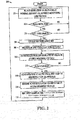
- FIG. 3 shows graphs 300, 310, 320 and 330 illustrating waveforms and state changes in the power conversion system 10 during operation according to the process 200.
- the graph 300 illustrates a DC bus voltage curve 302 representing the voltage Vdc.
- a curve 312 in the graph 310 shows a rectifier setpoint value used by the rectifier controller 62 in regulating the DC bus voltage in the first mode
- a curve 322 in graph 320 shows the operating state (OR) of the rectifier 30 in the first and second modes.
- the graph 330 includes a curve tree 22 showing the control operating state of the inverter 50, which transitions between controlling the AC output in the first mode and controlling or regulating the DC bus voltage in the second mode.
- an abnormal grid condition is detected at time T1
- the controller 60 responds by changing from the first mode operation to the second mode operation, including turning off the rectifier and causing the inverter 50 to control the DC bus voltage.
- the DC bus voltage curve 302 undergoes an increase from T1 through T2 during regulation by the inverter 50.
- the inverter 50 may regulate the DC bus voltage using closed loop control regulation to provide a more stable DC bus voltage level than as shown in the example of FIG. 3 .
- the controller 60 may obtain a measurement of the DC bus voltage Vdc in response to detection of an abnormal grid condition, and use this value as a setpoint reference for regulation by the inverter controller 66 in the second mode.
- the controller 60 detects clearance of the fault condition (YES at 212 in FIG. 2 above), and in response to this fault clearance detection, changes from the second mode to the first mode.
- the controller 60 again measures the DC bus voltage at 214, shown in the graphs 300 and 310 of FIG. 3 as the measured voltage VM.
- the first mode DC bus voltage regulation by the rectifier controller 62 uses a nominal reference voltage or setpoint shown in graphs 300 and 310 as VNOM. Changeover from inverter regulation to rectifier regulation following time T2 may lead to a slight ramp down in the DC bus voltage from T2 through T3 as shown in the curve 302 in FIG. 3 .
- the controller 60 begins the resumption of rectifier-based DC bus voltage regulation at T2 according to a setpoint value that is set to the measured value VM. Thereafter, from T2 through T4, the controller 60 ramps down the setpoint value (e.g., curve 312 in FIG. 3 ) to the nominal value VNOM, and the closed loop regulation of the DC bus voltage curve 302 generally tracks this ramped setpoint. Absent this ramp operation, the rectifier 30 may begin operation at T2 using the nominal setpoint, which can be significantly different from the current operating level of the DC bus circuit 40. In that case, the rectifier control can attempt to overcompensate for the setpoint difference, leading to excessive rectifier currents.
- the setpoint value e.g., curve 312 in FIG. 3
- High rectifier currents can lead to undesired tripping of the motor drive power conversion system 10.
- the regulation of the DC bus voltage during brief or transitory abnormal grid conditions helps to avoid or mitigate undesired tripping based on low DC bus voltage levels in the intermediate circuit 40.
- the concepts of the present disclosure provide advanced abnormal grid condition ride through functions using pre-existing hardware in the motor drive 10 to facilitate continued operation of the system 10 and reduce the likelihood of shutdowns due to overcurrent or under voltage trips during transient grid voltage disturbances or faults.
- the terms (including a reference to a "means") used to describe such components are intended to correspond, unless otherwise indicated, to any component, such as hardware, processor-executed software, or combinations thereof, which performs the specified function of the described component (i.e., that is functionally equivalent), even though not structurally equivalent to the disclosed structure which performs the function in the illustrated implementations of the disclosure.
- any component such as hardware, processor-executed software, or combinations thereof, which performs the specified function of the described component (i.e., that is functionally equivalent), even though not structurally equivalent to the disclosed structure which performs the function in the illustrated implementations of the disclosure.
- a particular feature of the disclosure may have been disclosed with respect to only one of several implementations, such feature may be combined with one or more other features of the other implementations as may be desired and advantageous for any given or particular application.
Landscapes
- Engineering & Computer Science (AREA)
- Power Engineering (AREA)
- Inverter Devices (AREA)
Claims (9)
- Leistungsumwandlungssystem (10), umfassend:eine AC-Eingabe, die koppelbar ist, um eine AC-Eingabeleistung von einer Leistungsquelle zu empfangen;einen Gleichrichter (30), der beinhaltet: mehrere AC-Eingabeanschlüsse, erste und zweite DC-Ausgabeanschlüsse und mehrere Gleichrichterschaltvorrichtungen (S1 bis S6), die einzeln zwischen einem entsprechenden der AC-Eingabeanschlüsse und einem der ersten und zweiten DC-Ausgabeanschlüsse gekoppelt sind;eine Filterschaltung (20), die zwischen der AC-Eingabe und dem Gleichrichter gekoppelt ist;einen Inverter (50), der beinhaltet: erste und zweite DC-Eingabeanschlüsse, mehrere AC-Ausgabeanschlüsse und mehrere Inverterschaltvorrichtungen (S7 bis S12), die einzeln zwischen einem entsprechenden der DC-Eingabeanschlüsse und einem der AC-Ausgabeanschlüsse gekoppelt sind;eine Zwischen-DC-Schaltung (40), die einen Kondensator beinhaltet, der zwischen den ersten und zweiten DC-Ausgabeanschlüssen des Gleichrichters gekoppelt ist; undeine Steuerung (60), die in einem ersten Modus dazu betreibbar ist, Gleichrichterschaltsteuersignale (62a) dafür bereitzustellen, die Gleichrichterschaltvorrichtungen (S1 bis S6) dazu zu betreiben, eine DC-Spannung der Zwischen-DC-Schaltung (40) entsprechend einem Einstellpunktwert zu regulieren, und Inverterschaltsteuersignale dafür bereitzustellen, die Inverterschaltvorrichtungen (S7 bis S12) dazu zu betreiben, die DC-Leistung von der Zwischen-DC-Schaltung (40) umzuwandeln, um eine AC-Ausgabeleistung für die AC-Ausgabeanschlüsse bereitzustellen;wobei die Steuerung (60) in einem zweiten Modus dazu betreibbar ist, die Gleichrichterschaltsteuersignale (62a) dafür bereitzustellen, die Gleichrichterschaltvorrichtungen (S1 bis S6) abzuschalten, und die Inverterschaltsteuersignale (66a) dafür bereitzustellen, die Inverterschaltvorrichtungen dazu zu betreiben, die DC-Spannung der Zwischen-DC-Schaltung (40) zu regulieren,wobei die Steuerung dazu betreibbar ist, eine Beseitigung einer anomalen Netzbedingung zu detektieren und von dem zweiten Modus zu dem ersten Modus in Reaktion auf eine Detektion einer Beseitigung der anomalen Netzbedingung zu wechseln,wobei die Steuerung des Weiteren betreibbar ist zum:Messen der DC-Spannung in Reaktion auf eine Detektion einer Beseitigung der anomalen Netzbedingung,anfänglichen Einstellen des Einstellpunktwertes auf den gemessenen DC-Spannungswert beim Wechseln von dem zweiten Modus zu dem ersten Modus, undVerschieben des Einstellpunktwertes zu einem nominalen Einstellpunktwert nach dem Wechseln von dem zweiten Modus zu dem ersten Modus.
- Leistungsumwandlungssystem nach Anspruch 1, wobei die Steuerung dazu betreibbar ist, die anomale Netzbedingung zu detektieren und von dem ersten Modus zu dem zweiten Modus in Reaktion auf eine Detektion der anomalen Netzbedingung zu wechseln.
- Leistungsumwandlungssystem nach Anspruch 1 oder 2, wobei die Steuerung (60) in dem zweiten Modus dazu betreibbar ist, die Inverterschaltsteuersignale dafür bereitzustellen, die Inverterschaltvorrichtungen (S7 bis S12) dazu zu betreiben, die DC-Spannung der Zwischen-DC-Schaltung (40) entsprechend einem Wert der DC-Spannung mit Messung in Reaktion auf eine Detektion einer anomalen Netzbedingung zu regulieren.
- Verfahren zum Betreiben eines Leistungsumwandlungssystems mit einem Gleichrichter (30), einem Inverter (50) und einer Zwischen-DC-Schaltung (40), die zwischen dem Gleichrichter (30) und dem Inverter (50) gekoppelt ist, wobei das Verfahren umfasst:in einem ersten Modus:Betreiben des Gleichrichters (30) dazu, eine DC-Spannung der Zwischen-DC-Schaltung (40) zu regulieren, undBetreiben des Inverters (50) dazu, eine DC-Leistung von der Zwischen-DC-Schaltung (40) umzuwandeln, um eine AC-Ausgabeleistung zum Antreiben einer Last (4) bereitzustellen;Betreiben des Gleichrichters (30) dazu, die DC-Spannung entsprechend einem Einstellpunktwert zu regulieren; undin einem zweiten Modus:Abschalten (206) des Gleichrichters (30), undBetreiben des Inverters (50) dazu, die DC-Spannung der Zwischen-DC-Schaltung (40) unter Nutzung von Leistung von der Last (4) zu regulieren, wobei das Verfahren des Weiteren umfasst:Detektieren (212) einer Beseitigung einer anomalen Netzbedingung; undWechseln von dem zweiten Modus zu dem ersten Modus in Reaktion auf eine Detektion einer Beseitigung der anomalen Netzbedingung,Messen (214) der DC-Spannung in Reaktion auf eine Detektion einer Beseitigung der anomalen Netzbedingung;anfängliches Einstellen (216) des Einstellpunktwertes auf den gemessenen DC-Spannungswert beim Wechseln von dem zweiten Modus zu dem ersten Modus; undVerschieben (218) des Einstellpunktwertes zu einem nominalen Einstellpunktwert nach dem Wechseln von dem zweiten Modus zu dem ersten Modus.
- Verfahren nach Anspruch 4, des Weiteren umfassend:Detektieren der anomalen Netzbedingung; undWechseln von dem ersten Modus zu dem zweiten Modus in Reaktion auf das Detektieren der anomalen Netzbedingung.
- Verfahren nach Anspruch 5, des Weiteren umfassend:in dem zweiten Modus erfolgendes Betreiben des Inverters (50) dazu, die DC-Spannung entsprechend einem Wert der DC-Spannung mit Messung in Reaktion auf das Detektieren einer anomalen Netzbedingung zu regulieren.
- Nichttemporäres computerlesbares Medium mit computerausführbaren Anweisungen zum Betreiben eines Leistungsumwandlungssystems mit einem Gleichrichter (30), einem Inverter (50) und einer Zwischen-DC-Schaltung (40), die zwischen dem Gleichrichter (30) und dem Inverter (50) gekoppelt ist, wobei das computerlesbare Medium computerausführbare Anweisungen umfasst zum:in einem ersten Modus:Betreiben des Gleichrichters (30) dazu, eine DC-Spannung der Zwischen-DC-Schaltung (40) zu regulieren, undBetreiben des Inverters (50) dazu, eine DC-Leistung von der Zwischen-DC-Schaltung (40) umzuwandeln, um eine AC-Ausgabeleistung zum Antreiben einer Last bereitzustellen;Betreiben des Gleichrichters (30) dazu, die DC-Spannung entsprechend einem Einstellpunktwert zu regulieren; undin einem zweiten Modus:Abschalten des Gleichrichters (30), undBetreiben des Inverters (50) dazu, die DC-Spannung der Zwischen-DC-Schaltung (40) unter Nutzung einer Leistung von der Last (4) zu regulieren, wobei das nichttemporäre computerlesbare Medium weitere computerausführbare Anweisungen umfasst zum:Detektieren (212) einer Beseitigung einer anomalen Netzbedingung; undWechseln von dem zweiten Modus zu dem ersten Modus in Reaktion auf das Detektieren einer Beseitigung der anomalen Netzbedingung,Messen (214) der DC-Spannung in Reaktion auf das Detektieren einer Beseitigung der anomalen Netzbedingung;anfänglichen Einstellen (216) des Einstellpunktwertes auf den gemessenen DC-Spannungswert beim Wechseln von dem zweiten Modus zu dem ersten Modus; undVerschieben (218) des Einstellpunktwertes zu einem nominalen Einstellpunktwert nach dem Wechseln von dem zweiten Modus zu dem ersten Modus.
- Nichttemporäres computerlesbares Medium nach Anspruch 7, des Weiteren umfassend computerausführbare Anweisungen zum:Detektieren der anomalen Netzbedingung;Wechseln von dem ersten Modus zu dem zweiten Modus in Reaktion auf das Detektieren der anomalen Netzbedingung.
- Nichttemporäres computerlesbares Medium nach Anspruch 8, des Weiteren umfassend computerausführbare Anweisungen zum:in dem zweiten Modus erfolgenden Betreiben des Inverters dazu, die DC-Spannung entsprechend einem Wert der DC-Spannung mit Messung in Reaktion auf das Detektieren einer anomalen Netzspannung zu regulieren.
Applications Claiming Priority (1)
| Application Number | Priority Date | Filing Date | Title |
|---|---|---|---|
| US15/152,961 US9847733B2 (en) | 2016-05-12 | 2016-05-12 | Power conversion system with DC bus regulation for abnormal grid condition ride through |
Publications (2)
| Publication Number | Publication Date |
|---|---|
| EP3244521A1 EP3244521A1 (de) | 2017-11-15 |
| EP3244521B1 true EP3244521B1 (de) | 2021-08-11 |
Family
ID=58669711
Family Applications (1)
| Application Number | Title | Priority Date | Filing Date |
|---|---|---|---|
| EP17169431.8A Active EP3244521B1 (de) | 2016-05-12 | 2017-05-04 | Stromwandlersystem mit gleichstrombusregelung für durchfahren abnormaler netzbedingungen |
Country Status (3)
| Country | Link |
|---|---|
| US (1) | US9847733B2 (de) |
| EP (1) | EP3244521B1 (de) |
| CN (1) | CN107370389B (de) |
Families Citing this family (6)
| Publication number | Priority date | Publication date | Assignee | Title |
|---|---|---|---|---|
| GB201610369D0 (en) * | 2016-06-15 | 2016-07-27 | Rolls Royce Plc | Control of an electrical converter |
| RU2686475C1 (ru) * | 2018-04-25 | 2019-04-29 | Фёдор Андреевич Гельвер | Преобразователь частоты с несимметричной схемой инвертора |
| DE102019118927A1 (de) * | 2019-07-12 | 2021-01-14 | Vacon Oy | Gleichstromzwischenkreisladeanordnung und Verfahren zum Laden eines Gleichstromzwischenkreiskondensators |
| US11146180B2 (en) | 2019-11-01 | 2021-10-12 | Rockwell Automation Technologies, Inc. | Linear and nonlinear dynamic bus control for AFE applications |
| CN111799787B (zh) * | 2020-07-13 | 2023-06-20 | 重庆理工大学 | 一种电网综合负荷系统的分析方法 |
| CN113629703B (zh) * | 2021-07-28 | 2024-05-07 | 南方电网科学研究院有限责任公司 | 一种常规直流系统故障恢复控制的优化方法 |
Citations (2)
| Publication number | Priority date | Publication date | Assignee | Title |
|---|---|---|---|---|
| US20030098668A1 (en) * | 2001-11-27 | 2003-05-29 | York International Corporation | Control loop and method for variable speed drive ride - through capability improvement |
| US7081734B1 (en) * | 2005-09-02 | 2006-07-25 | York International Corporation | Ride-through method and system for HVACandR chillers |
Family Cites Families (41)
| Publication number | Priority date | Publication date | Assignee | Title |
|---|---|---|---|---|
| US3757197A (en) | 1972-07-25 | 1973-09-04 | Gen Electric | Amping voltage on series compensating capacitor series parallel compensated current source inverter with means for cl |
| JPS605151B2 (ja) | 1978-04-05 | 1985-02-08 | 株式会社日立製作所 | 多重化電流形インバ−タの制御方法 |
| US4434376A (en) | 1979-07-23 | 1984-02-28 | Electric Power Research Institute, Inc. | Method and means for damping subsynchronous oscillations and DC offset in an AC power system |
| US4545002A (en) | 1983-06-28 | 1985-10-01 | General Electric Company | Thyristor voltage limiter for current source inverter |
| US4496899A (en) | 1983-06-28 | 1985-01-29 | General Electric Company | Control for a force commutated current source var generator |
| US4833389A (en) | 1988-09-26 | 1989-05-23 | Westinghouse Electric Corp. | Current source inverter control system for load commutated induction motor drive |
| US4870338A (en) | 1988-09-26 | 1989-09-26 | Westinghouse Electric Corp. | Load commutated inverter (LCI) induction motor drive |
| US5005115A (en) | 1989-07-28 | 1991-04-02 | Westinghouse Electric Corp. | Forced-commutated current-source converter and AC motor drive using the same |
| US5041959A (en) | 1990-08-14 | 1991-08-20 | General Electric Company | Control system for a current source converter supplying an AC bus |
| GB2298533A (en) | 1994-07-29 | 1996-09-04 | Texas Instruments Ltd | Overvoltage protector |
| DE19821887B4 (de) * | 1997-05-20 | 2015-03-05 | Kimo Industrie-Elektronik Gmbh | Verfahren zum Betrieb einer Umrichter-Schaltungsanordnung zur Ansteuerung eines Elektromotors |
| US6005362A (en) | 1998-02-13 | 1999-12-21 | The Texas A&M University Systems | Method and system for ride-through of an adjustable speed drive for voltage sags and short-term power interruption |
| US6118676A (en) | 1998-11-06 | 2000-09-12 | Soft Switching Technologies Corp. | Dynamic voltage sag correction |
| US6275391B1 (en) | 2000-04-06 | 2001-08-14 | General Electric Company | Compact push-pull converter and crowbar circuit, and control therefor |
| CN100356683C (zh) | 2002-01-29 | 2007-12-19 | 威斯塔斯风力系统公开有限公司 | 用于风力装置中的电路结构 |
| US7129599B2 (en) | 2002-10-15 | 2006-10-31 | Soft Switching Technologies Corporation | Dual feed power supply systems with enhanced power quality |
| FI116174B (fi) | 2003-04-08 | 2005-09-30 | Abb Oy | Kokoonpano ja menetelmä suuntaajavälineiden suojaamiseksi |
| EP1625457A4 (de) | 2003-05-02 | 2015-04-22 | Xantrex Technology Inc | Steuersystem für zweifach gespeisten induktionsgenerator |
| EP1499009B1 (de) | 2003-07-15 | 2007-10-31 | Gamesa Innovation & Technology, S.L. Unipersonal | Steuer- und Schutzgerät für ein doppelgespeistes Induktionsgeneratorsystem |
| US7164254B2 (en) | 2005-02-28 | 2007-01-16 | Rockwell Automation Technologies, Inc. | Modulation methods and apparatus for reducing common mode voltages |
| US7173399B2 (en) | 2005-04-19 | 2007-02-06 | General Electric Company | Integrated torsional mode damping system and method |
| US7514907B2 (en) | 2005-05-24 | 2009-04-07 | Satcon Technology Corporation | Device, system, and method for providing a low-voltage fault ride-through for a wind generator farm |
| ES2296483B1 (es) | 2005-11-21 | 2009-03-01 | Ingeteam Technology, S.A. | Un sistema de control y proteccion ante faltas simetricas y asimetricas, para generadores de tipo asincrono. |
| US7253537B2 (en) | 2005-12-08 | 2007-08-07 | General Electric Company | System and method of operating double fed induction generators |
| US7423412B2 (en) | 2006-01-31 | 2008-09-09 | General Electric Company | Method, apparatus and computer program product for injecting current |
| US7193387B1 (en) | 2006-03-14 | 2007-03-20 | Rockwell Automation Technologies, Inc. | System and method for motor speed estimation using hybrid model reference adaptive system |
| US7649756B2 (en) | 2006-05-17 | 2010-01-19 | Rockwell Automation Technologies, Inc. | Common mode noise reduction in converter systems through modification of single phase switching signal |
| US7358700B2 (en) | 2006-09-14 | 2008-04-15 | Rockwell Automation Technologies, Inc. | Induction motor controller |
| US7622815B2 (en) | 2006-12-29 | 2009-11-24 | Ingeteam Energy, S.A. | Low voltage ride through system for a variable speed wind turbine having an exciter machine and a power converter not connected to the grid |
| US8203304B2 (en) | 2007-08-31 | 2012-06-19 | Rockwell Automation Technologies, Inc. | Control method and system with feedback indicative of load flux |
| JP2009225581A (ja) | 2008-03-17 | 2009-10-01 | Daikin Ind Ltd | 電力変換装置 |
| US8030791B2 (en) | 2008-07-31 | 2011-10-04 | Rockwell Automation Technologies, Inc. | Current source converter-based wind energy system |
| CN101383576B (zh) | 2008-10-28 | 2010-12-29 | 华北电力大学(保定) | 一种大型风力发电机组穿越电网低电压故障的方法 |
| US8259426B2 (en) * | 2010-05-28 | 2012-09-04 | Rockwell Automation Technologies, Inc. | Variable frequency drive and methods for filter capacitor fault detection |
| US9184685B2 (en) | 2010-10-28 | 2015-11-10 | Vestas Wind Systems A/S | Wind turbine generator |
| US8570003B2 (en) | 2011-04-13 | 2013-10-29 | Rockwell Automation Technologies, Inc. | Double fed induction generator converter and method for suppressing transient in deactivation of crowbar circuit for grid fault ridethrough |
| CN102214931B (zh) | 2011-05-24 | 2014-06-11 | 浙江大学 | 双馈感应风力发电机系统低电压穿越的方法 |
| JP5260719B2 (ja) | 2011-11-30 | 2013-08-14 | ファナック株式会社 | 停電の有無を判定する停電判定部を有するモータ駆動装置 |
| US8907510B2 (en) * | 2012-03-09 | 2014-12-09 | General Electric Company | Method and systems for operating a wind turbine |
| US9041234B2 (en) | 2012-03-26 | 2015-05-26 | Rockwell Automation Technologies, Inc. | Double fed induction generator (DFIG) converter and method for improved grid fault ridethrough |
| EP2842221A4 (de) * | 2012-04-26 | 2016-05-11 | Gen Electric | Stromwandlersystem, dämpfungssystem und verfahren zum betrieb eines stromwandlersystems |
-
2016
- 2016-05-12 US US15/152,961 patent/US9847733B2/en active Active
-
2017
- 2017-05-04 EP EP17169431.8A patent/EP3244521B1/de active Active
- 2017-05-12 CN CN201710333799.XA patent/CN107370389B/zh active Active
Patent Citations (2)
| Publication number | Priority date | Publication date | Assignee | Title |
|---|---|---|---|---|
| US20030098668A1 (en) * | 2001-11-27 | 2003-05-29 | York International Corporation | Control loop and method for variable speed drive ride - through capability improvement |
| US7081734B1 (en) * | 2005-09-02 | 2006-07-25 | York International Corporation | Ride-through method and system for HVACandR chillers |
Also Published As
| Publication number | Publication date |
|---|---|
| US9847733B2 (en) | 2017-12-19 |
| CN107370389B (zh) | 2019-06-28 |
| US20170331389A1 (en) | 2017-11-16 |
| EP3244521A1 (de) | 2017-11-15 |
| CN107370389A (zh) | 2017-11-21 |
Similar Documents
| Publication | Publication Date | Title |
|---|---|---|
| EP3244521B1 (de) | Stromwandlersystem mit gleichstrombusregelung für durchfahren abnormaler netzbedingungen | |
| US8937796B2 (en) | Variable frequency drive and methods for filter capacitor fault detection | |
| US10063161B2 (en) | Active neutral point clamped converter control system and method | |
| US8970159B2 (en) | Method for compensating instantaneous power failure in medium voltage inverter and medium voltage inverter system by using the same | |
| US11128237B2 (en) | Electrically coupling a first electrical supply network to a second electrical supply network | |
| US11031896B2 (en) | Motor driving apparatus and refrigeration cycle equipment | |
| JP6075067B2 (ja) | 電力変換装置 | |
| CN112840522B (zh) | 电源装置以及交流电源的异常检测方法 | |
| US12113395B2 (en) | Power converter | |
| JP2010239736A (ja) | 電力変換装置 | |
| EP3011674B1 (de) | Antrieb mit zwei leistungsbetriebsarten | |
| CN114447979B (zh) | 一种功率变换装置和功率变换装置的控制方法 | |
| JP5302905B2 (ja) | 電力変換装置 | |
| EP3264559A1 (de) | Steuerung des betriebs eines leistungswandlers basierend auf netzbedingungen | |
| JP3773798B2 (ja) | 電力変換装置 | |
| US20200235674A1 (en) | Power supply control device, power conversion system, and power supply control method | |
| KR20150005822A (ko) | H-브리지 멀티 레벨 인버터의 순간정전 제어 장치 및 방법 | |
| JP5652975B1 (ja) | モータ制御装置 | |
| JP2019062660A (ja) | 電圧調整装置 | |
| JP3650566B2 (ja) | 電力変換装置 | |
| US9425702B2 (en) | System and method for safe switching in an AC-to-AC converter | |
| EP3584916B1 (de) | Verfahren zur steuerung eines wechselrichters | |
| JP4235910B2 (ja) | 巻線形誘導電動機の制御装置 | |
| US20240380352A1 (en) | Power converter, motor drive system, and power conversion method | |
| PH12018000166A1 (en) | Motor control apparatus |
Legal Events
| Date | Code | Title | Description |
|---|---|---|---|
| PUAI | Public reference made under article 153(3) epc to a published international application that has entered the european phase |
Free format text: ORIGINAL CODE: 0009012 |
|
| STAA | Information on the status of an ep patent application or granted ep patent |
Free format text: STATUS: THE APPLICATION HAS BEEN PUBLISHED |
|
| AK | Designated contracting states |
Kind code of ref document: A1 Designated state(s): AL AT BE BG CH CY CZ DE DK EE ES FI FR GB GR HR HU IE IS IT LI LT LU LV MC MK MT NL NO PL PT RO RS SE SI SK SM TR |
|
| AX | Request for extension of the european patent |
Extension state: BA ME |
|
| STAA | Information on the status of an ep patent application or granted ep patent |
Free format text: STATUS: REQUEST FOR EXAMINATION WAS MADE |
|
| 17P | Request for examination filed |
Effective date: 20180515 |
|
| RBV | Designated contracting states (corrected) |
Designated state(s): AL AT BE BG CH CY CZ DE DK EE ES FI FR GB GR HR HU IE IS IT LI LT LU LV MC MK MT NL NO PL PT RO RS SE SI SK SM TR |
|
| STAA | Information on the status of an ep patent application or granted ep patent |
Free format text: STATUS: EXAMINATION IS IN PROGRESS |
|
| 17Q | First examination report despatched |
Effective date: 20190404 |
|
| GRAP | Despatch of communication of intention to grant a patent |
Free format text: ORIGINAL CODE: EPIDOSNIGR1 |
|
| STAA | Information on the status of an ep patent application or granted ep patent |
Free format text: STATUS: GRANT OF PATENT IS INTENDED |
|
| RIC1 | Information provided on ipc code assigned before grant |
Ipc: H02P 29/024 20160101ALI20210121BHEP Ipc: H02P 29/00 20160101ALI20210121BHEP Ipc: H02P 27/06 20060101ALI20210121BHEP Ipc: H02M 5/458 20060101ALI20210121BHEP Ipc: H02M 1/08 20060101ALN20210121BHEP Ipc: H02M 1/32 20070101AFI20210121BHEP |
|
| RIC1 | Information provided on ipc code assigned before grant |
Ipc: H02P 27/06 20060101ALI20210126BHEP Ipc: H02M 1/32 20070101AFI20210126BHEP Ipc: H02P 29/00 20160101ALI20210126BHEP Ipc: H02P 29/024 20160101ALI20210126BHEP Ipc: H02M 1/08 20060101ALN20210126BHEP Ipc: H02M 5/458 20060101ALI20210126BHEP |
|
| INTG | Intention to grant announced |
Effective date: 20210212 |
|
| GRAS | Grant fee paid |
Free format text: ORIGINAL CODE: EPIDOSNIGR3 |
|
| GRAA | (expected) grant |
Free format text: ORIGINAL CODE: 0009210 |
|
| STAA | Information on the status of an ep patent application or granted ep patent |
Free format text: STATUS: THE PATENT HAS BEEN GRANTED |
|
| AK | Designated contracting states |
Kind code of ref document: B1 Designated state(s): AL AT BE BG CH CY CZ DE DK EE ES FI FR GB GR HR HU IE IS IT LI LT LU LV MC MK MT NL NO PL PT RO RS SE SI SK SM TR |
|
| REG | Reference to a national code |
Ref country code: CH Ref legal event code: EP |
|
| REG | Reference to a national code |
Ref country code: DE Ref legal event code: R096 Ref document number: 602017043692 Country of ref document: DE |
|
| REG | Reference to a national code |
Ref country code: IE Ref legal event code: FG4D Ref country code: AT Ref legal event code: REF Ref document number: 1420412 Country of ref document: AT Kind code of ref document: T Effective date: 20210915 |
|
| REG | Reference to a national code |
Ref country code: LT Ref legal event code: MG9D |
|
| REG | Reference to a national code |
Ref country code: NL Ref legal event code: MP Effective date: 20210811 |
|
| REG | Reference to a national code |
Ref country code: AT Ref legal event code: MK05 Ref document number: 1420412 Country of ref document: AT Kind code of ref document: T Effective date: 20210811 |
|
| PG25 | Lapsed in a contracting state [announced via postgrant information from national office to epo] |
Ref country code: RS Free format text: LAPSE BECAUSE OF FAILURE TO SUBMIT A TRANSLATION OF THE DESCRIPTION OR TO PAY THE FEE WITHIN THE PRESCRIBED TIME-LIMIT Effective date: 20210811 Ref country code: SE Free format text: LAPSE BECAUSE OF FAILURE TO SUBMIT A TRANSLATION OF THE DESCRIPTION OR TO PAY THE FEE WITHIN THE PRESCRIBED TIME-LIMIT Effective date: 20210811 Ref country code: FI Free format text: LAPSE BECAUSE OF FAILURE TO SUBMIT A TRANSLATION OF THE DESCRIPTION OR TO PAY THE FEE WITHIN THE PRESCRIBED TIME-LIMIT Effective date: 20210811 Ref country code: ES Free format text: LAPSE BECAUSE OF FAILURE TO SUBMIT A TRANSLATION OF THE DESCRIPTION OR TO PAY THE FEE WITHIN THE PRESCRIBED TIME-LIMIT Effective date: 20210811 Ref country code: HR Free format text: LAPSE BECAUSE OF FAILURE TO SUBMIT A TRANSLATION OF THE DESCRIPTION OR TO PAY THE FEE WITHIN THE PRESCRIBED TIME-LIMIT Effective date: 20210811 Ref country code: PT Free format text: LAPSE BECAUSE OF FAILURE TO SUBMIT A TRANSLATION OF THE DESCRIPTION OR TO PAY THE FEE WITHIN THE PRESCRIBED TIME-LIMIT Effective date: 20211213 Ref country code: NO Free format text: LAPSE BECAUSE OF FAILURE TO SUBMIT A TRANSLATION OF THE DESCRIPTION OR TO PAY THE FEE WITHIN THE PRESCRIBED TIME-LIMIT Effective date: 20211111 Ref country code: AT Free format text: LAPSE BECAUSE OF FAILURE TO SUBMIT A TRANSLATION OF THE DESCRIPTION OR TO PAY THE FEE WITHIN THE PRESCRIBED TIME-LIMIT Effective date: 20210811 Ref country code: BG Free format text: LAPSE BECAUSE OF FAILURE TO SUBMIT A TRANSLATION OF THE DESCRIPTION OR TO PAY THE FEE WITHIN THE PRESCRIBED TIME-LIMIT Effective date: 20211111 Ref country code: LT Free format text: LAPSE BECAUSE OF FAILURE TO SUBMIT A TRANSLATION OF THE DESCRIPTION OR TO PAY THE FEE WITHIN THE PRESCRIBED TIME-LIMIT Effective date: 20210811 |
|
| PG25 | Lapsed in a contracting state [announced via postgrant information from national office to epo] |
Ref country code: PL Free format text: LAPSE BECAUSE OF FAILURE TO SUBMIT A TRANSLATION OF THE DESCRIPTION OR TO PAY THE FEE WITHIN THE PRESCRIBED TIME-LIMIT Effective date: 20210811 Ref country code: LV Free format text: LAPSE BECAUSE OF FAILURE TO SUBMIT A TRANSLATION OF THE DESCRIPTION OR TO PAY THE FEE WITHIN THE PRESCRIBED TIME-LIMIT Effective date: 20210811 Ref country code: GR Free format text: LAPSE BECAUSE OF FAILURE TO SUBMIT A TRANSLATION OF THE DESCRIPTION OR TO PAY THE FEE WITHIN THE PRESCRIBED TIME-LIMIT Effective date: 20211112 |
|
| PG25 | Lapsed in a contracting state [announced via postgrant information from national office to epo] |
Ref country code: NL Free format text: LAPSE BECAUSE OF FAILURE TO SUBMIT A TRANSLATION OF THE DESCRIPTION OR TO PAY THE FEE WITHIN THE PRESCRIBED TIME-LIMIT Effective date: 20210811 |
|
| PG25 | Lapsed in a contracting state [announced via postgrant information from national office to epo] |
Ref country code: DK Free format text: LAPSE BECAUSE OF FAILURE TO SUBMIT A TRANSLATION OF THE DESCRIPTION OR TO PAY THE FEE WITHIN THE PRESCRIBED TIME-LIMIT Effective date: 20210811 |
|
| REG | Reference to a national code |
Ref country code: DE Ref legal event code: R097 Ref document number: 602017043692 Country of ref document: DE |
|
| PG25 | Lapsed in a contracting state [announced via postgrant information from national office to epo] |
Ref country code: SM Free format text: LAPSE BECAUSE OF FAILURE TO SUBMIT A TRANSLATION OF THE DESCRIPTION OR TO PAY THE FEE WITHIN THE PRESCRIBED TIME-LIMIT Effective date: 20210811 Ref country code: SK Free format text: LAPSE BECAUSE OF FAILURE TO SUBMIT A TRANSLATION OF THE DESCRIPTION OR TO PAY THE FEE WITHIN THE PRESCRIBED TIME-LIMIT Effective date: 20210811 Ref country code: RO Free format text: LAPSE BECAUSE OF FAILURE TO SUBMIT A TRANSLATION OF THE DESCRIPTION OR TO PAY THE FEE WITHIN THE PRESCRIBED TIME-LIMIT Effective date: 20210811 Ref country code: EE Free format text: LAPSE BECAUSE OF FAILURE TO SUBMIT A TRANSLATION OF THE DESCRIPTION OR TO PAY THE FEE WITHIN THE PRESCRIBED TIME-LIMIT Effective date: 20210811 Ref country code: CZ Free format text: LAPSE BECAUSE OF FAILURE TO SUBMIT A TRANSLATION OF THE DESCRIPTION OR TO PAY THE FEE WITHIN THE PRESCRIBED TIME-LIMIT Effective date: 20210811 Ref country code: AL Free format text: LAPSE BECAUSE OF FAILURE TO SUBMIT A TRANSLATION OF THE DESCRIPTION OR TO PAY THE FEE WITHIN THE PRESCRIBED TIME-LIMIT Effective date: 20210811 |
|
| PLBE | No opposition filed within time limit |
Free format text: ORIGINAL CODE: 0009261 |
|
| STAA | Information on the status of an ep patent application or granted ep patent |
Free format text: STATUS: NO OPPOSITION FILED WITHIN TIME LIMIT |
|
| 26N | No opposition filed |
Effective date: 20220512 |
|
| PG25 | Lapsed in a contracting state [announced via postgrant information from national office to epo] |
Ref country code: IT Free format text: LAPSE BECAUSE OF FAILURE TO SUBMIT A TRANSLATION OF THE DESCRIPTION OR TO PAY THE FEE WITHIN THE PRESCRIBED TIME-LIMIT Effective date: 20210811 |
|
| PG25 | Lapsed in a contracting state [announced via postgrant information from national office to epo] |
Ref country code: SI Free format text: LAPSE BECAUSE OF FAILURE TO SUBMIT A TRANSLATION OF THE DESCRIPTION OR TO PAY THE FEE WITHIN THE PRESCRIBED TIME-LIMIT Effective date: 20210811 |
|
| REG | Reference to a national code |
Ref country code: CH Ref legal event code: PL |
|
| REG | Reference to a national code |
Ref country code: BE Ref legal event code: MM Effective date: 20220531 |
|
| PG25 | Lapsed in a contracting state [announced via postgrant information from national office to epo] |
Ref country code: MC Free format text: LAPSE BECAUSE OF FAILURE TO SUBMIT A TRANSLATION OF THE DESCRIPTION OR TO PAY THE FEE WITHIN THE PRESCRIBED TIME-LIMIT Effective date: 20210811 Ref country code: LU Free format text: LAPSE BECAUSE OF NON-PAYMENT OF DUE FEES Effective date: 20220504 Ref country code: LI Free format text: LAPSE BECAUSE OF NON-PAYMENT OF DUE FEES Effective date: 20220531 Ref country code: CH Free format text: LAPSE BECAUSE OF NON-PAYMENT OF DUE FEES Effective date: 20220531 |
|
| PG25 | Lapsed in a contracting state [announced via postgrant information from national office to epo] |
Ref country code: IE Free format text: LAPSE BECAUSE OF NON-PAYMENT OF DUE FEES Effective date: 20220504 |
|
| PG25 | Lapsed in a contracting state [announced via postgrant information from national office to epo] |
Ref country code: BE Free format text: LAPSE BECAUSE OF NON-PAYMENT OF DUE FEES Effective date: 20220531 |
|
| P01 | Opt-out of the competence of the unified patent court (upc) registered |
Effective date: 20230404 |
|
| PG25 | Lapsed in a contracting state [announced via postgrant information from national office to epo] |
Ref country code: HU Free format text: LAPSE BECAUSE OF FAILURE TO SUBMIT A TRANSLATION OF THE DESCRIPTION OR TO PAY THE FEE WITHIN THE PRESCRIBED TIME-LIMIT; INVALID AB INITIO Effective date: 20170504 |
|
| PG25 | Lapsed in a contracting state [announced via postgrant information from national office to epo] |
Ref country code: MK Free format text: LAPSE BECAUSE OF FAILURE TO SUBMIT A TRANSLATION OF THE DESCRIPTION OR TO PAY THE FEE WITHIN THE PRESCRIBED TIME-LIMIT Effective date: 20210811 Ref country code: CY Free format text: LAPSE BECAUSE OF FAILURE TO SUBMIT A TRANSLATION OF THE DESCRIPTION OR TO PAY THE FEE WITHIN THE PRESCRIBED TIME-LIMIT Effective date: 20210811 |
|
| PG25 | Lapsed in a contracting state [announced via postgrant information from national office to epo] |
Ref country code: TR Free format text: LAPSE BECAUSE OF FAILURE TO SUBMIT A TRANSLATION OF THE DESCRIPTION OR TO PAY THE FEE WITHIN THE PRESCRIBED TIME-LIMIT Effective date: 20210811 |
|
| PG25 | Lapsed in a contracting state [announced via postgrant information from national office to epo] |
Ref country code: MT Free format text: LAPSE BECAUSE OF FAILURE TO SUBMIT A TRANSLATION OF THE DESCRIPTION OR TO PAY THE FEE WITHIN THE PRESCRIBED TIME-LIMIT Effective date: 20210811 |
|
| PGFP | Annual fee paid to national office [announced via postgrant information from national office to epo] |
Ref country code: DE Payment date: 20250423 Year of fee payment: 9 |
|
| PGFP | Annual fee paid to national office [announced via postgrant information from national office to epo] |
Ref country code: GB Payment date: 20250423 Year of fee payment: 9 |
|
| PGFP | Annual fee paid to national office [announced via postgrant information from national office to epo] |
Ref country code: FR Payment date: 20250423 Year of fee payment: 9 |