EP3244523B1 - Dispositif photovoltaïque courant alternatif-courant continu - Google Patents
Dispositif photovoltaïque courant alternatif-courant continu Download PDFInfo
- Publication number
- EP3244523B1 EP3244523B1 EP17163347.2A EP17163347A EP3244523B1 EP 3244523 B1 EP3244523 B1 EP 3244523B1 EP 17163347 A EP17163347 A EP 17163347A EP 3244523 B1 EP3244523 B1 EP 3244523B1
- Authority
- EP
- European Patent Office
- Prior art keywords
- pwm
- switching circuit
- power switching
- direct current
- photovoltaic
- Prior art date
- Legal status (The legal status is an assumption and is not a legal conclusion. Google has not performed a legal analysis and makes no representation as to the accuracy of the status listed.)
- Active
Links
Images





Classifications
-
- H—ELECTRICITY
- H02—GENERATION; CONVERSION OR DISTRIBUTION OF ELECTRIC POWER
- H02S—GENERATION OF ELECTRIC POWER BY CONVERSION OF INFRARED RADIATION, VISIBLE LIGHT OR ULTRAVIOLET LIGHT, e.g. USING PHOTOVOLTAIC [PV] MODULES
- H02S40/00—Components or accessories in combination with PV modules, not provided for in groups H02S10/00 - H02S30/00
- H02S40/30—Electrical components
-
- H—ELECTRICITY
- H02—GENERATION; CONVERSION OR DISTRIBUTION OF ELECTRIC POWER
- H02M—APPARATUS FOR CONVERSION BETWEEN AC AND AC, BETWEEN AC AND DC, OR BETWEEN DC AND DC, AND FOR USE WITH MAINS OR SIMILAR POWER SUPPLY SYSTEMS; CONVERSION OF DC OR AC INPUT POWER INTO SURGE OUTPUT POWER; CONTROL OR REGULATION THEREOF
- H02M3/00—Conversion of DC power input into DC power output
- H02M3/02—Conversion of DC power input into DC power output without intermediate conversion into AC
- H02M3/04—Conversion of DC power input into DC power output without intermediate conversion into AC by static converters
- H02M3/10—Conversion of DC power input into DC power output without intermediate conversion into AC by static converters using discharge tubes with control electrode or semiconductor devices with control electrode
- H02M3/145—Conversion of DC power input into DC power output without intermediate conversion into AC by static converters using discharge tubes with control electrode or semiconductor devices with control electrode using devices of a triode or transistor type requiring continuous application of a control signal
- H02M3/155—Conversion of DC power input into DC power output without intermediate conversion into AC by static converters using discharge tubes with control electrode or semiconductor devices with control electrode using devices of a triode or transistor type requiring continuous application of a control signal using semiconductor devices only
- H02M3/156—Conversion of DC power input into DC power output without intermediate conversion into AC by static converters using discharge tubes with control electrode or semiconductor devices with control electrode using devices of a triode or transistor type requiring continuous application of a control signal using semiconductor devices only with automatic control of output voltage or current, e.g. switching regulators
- H02M3/158—Conversion of DC power input into DC power output without intermediate conversion into AC by static converters using discharge tubes with control electrode or semiconductor devices with control electrode using devices of a triode or transistor type requiring continuous application of a control signal using semiconductor devices only with automatic control of output voltage or current, e.g. switching regulators including plural semiconductor devices as final control devices for a single load
-
- F—MECHANICAL ENGINEERING; LIGHTING; HEATING; WEAPONS; BLASTING
- F21—LIGHTING
- F21S—NON-PORTABLE LIGHTING DEVICES; SYSTEMS THEREOF; VEHICLE LIGHTING DEVICES SPECIALLY ADAPTED FOR VEHICLE EXTERIORS
- F21S8/00—Lighting devices intended for fixed installation
- F21S8/08—Lighting devices intended for fixed installation with a standard
- F21S8/085—Lighting devices intended for fixed installation with a standard of high-built type, e.g. street light
-
- F—MECHANICAL ENGINEERING; LIGHTING; HEATING; WEAPONS; BLASTING
- F21—LIGHTING
- F21S—NON-PORTABLE LIGHTING DEVICES; SYSTEMS THEREOF; VEHICLE LIGHTING DEVICES SPECIALLY ADAPTED FOR VEHICLE EXTERIORS
- F21S9/00—Lighting devices with a built-in power supply; Systems employing lighting devices with a built-in power supply
- F21S9/02—Lighting devices with a built-in power supply; Systems employing lighting devices with a built-in power supply the power supply being a battery or accumulator
- F21S9/03—Lighting devices with a built-in power supply; Systems employing lighting devices with a built-in power supply the power supply being a battery or accumulator rechargeable by exposure to light
-
- H—ELECTRICITY
- H02—GENERATION; CONVERSION OR DISTRIBUTION OF ELECTRIC POWER
- H02J—ELECTRIC POWER NETWORKS; CIRCUIT ARRANGEMENTS OR SYSTEMS FOR SUPPLYING OR DISTRIBUTING ELECTRIC POWER; SYSTEMS FOR STORING ELECTRIC ENERGY
- H02J1/00—Circuit arrangements for DC mains or DC distribution networks
- H02J1/10—Parallel operation of DC sources
-
- H—ELECTRICITY
- H02—GENERATION; CONVERSION OR DISTRIBUTION OF ELECTRIC POWER
- H02J—ELECTRIC POWER NETWORKS; CIRCUIT ARRANGEMENTS OR SYSTEMS FOR SUPPLYING OR DISTRIBUTING ELECTRIC POWER; SYSTEMS FOR STORING ELECTRIC ENERGY
- H02J3/00—Circuit arrangements for AC mains or AC distribution networks
- H02J3/38—Arrangements for feeding a single network from two or more generators or sources in parallel; Arrangements for feeding already energised networks from additional generators or sources in parallel
- H02J3/381—Dispersed generators
-
- H—ELECTRICITY
- H02—GENERATION; CONVERSION OR DISTRIBUTION OF ELECTRIC POWER
- H02M—APPARATUS FOR CONVERSION BETWEEN AC AND AC, BETWEEN AC AND DC, OR BETWEEN DC AND DC, AND FOR USE WITH MAINS OR SIMILAR POWER SUPPLY SYSTEMS; CONVERSION OF DC OR AC INPUT POWER INTO SURGE OUTPUT POWER; CONTROL OR REGULATION THEREOF
- H02M7/00—Conversion of AC power input into DC power output; Conversion of DC power input into AC power output
- H02M7/42—Conversion of DC power input into AC power output without possibility of reversal
- H02M7/44—Conversion of DC power input into AC power output without possibility of reversal by static converters
- H02M7/48—Conversion of DC power input into AC power output without possibility of reversal by static converters using discharge tubes with control electrode or semiconductor devices with control electrode
- H02M7/53—Conversion of DC power input into AC power output without possibility of reversal by static converters using discharge tubes with control electrode or semiconductor devices with control electrode using devices of a triode or transistor type requiring continuous application of a control signal
- H02M7/537—Conversion of DC power input into AC power output without possibility of reversal by static converters using discharge tubes with control electrode or semiconductor devices with control electrode using devices of a triode or transistor type requiring continuous application of a control signal using semiconductor devices only, e.g. single switched pulse inverters
- H02M7/5387—Conversion of DC power input into AC power output without possibility of reversal by static converters using discharge tubes with control electrode or semiconductor devices with control electrode using devices of a triode or transistor type requiring continuous application of a control signal using semiconductor devices only, e.g. single switched pulse inverters in a bridge configuration
- H02M7/53871—Conversion of DC power input into AC power output without possibility of reversal by static converters using discharge tubes with control electrode or semiconductor devices with control electrode using devices of a triode or transistor type requiring continuous application of a control signal using semiconductor devices only, e.g. single switched pulse inverters in a bridge configuration with automatic control of output voltage or current
-
- H—ELECTRICITY
- H02—GENERATION; CONVERSION OR DISTRIBUTION OF ELECTRIC POWER
- H02P—CONTROL OR REGULATION OF ELECTRIC MOTORS, ELECTRIC GENERATORS OR DYNAMO-ELECTRIC CONVERTERS; CONTROLLING TRANSFORMERS, REACTORS OR CHOKE COILS
- H02P7/00—Arrangements for regulating or controlling the speed or torque of electric DC motors
- H02P7/06—Arrangements for regulating or controlling the speed or torque of electric DC motors for regulating or controlling an individual DC dynamo-electric motor by varying field or armature current
- H02P7/18—Arrangements for regulating or controlling the speed or torque of electric DC motors for regulating or controlling an individual DC dynamo-electric motor by varying field or armature current by master control with auxiliary power
- H02P7/24—Arrangements for regulating or controlling the speed or torque of electric DC motors for regulating or controlling an individual DC dynamo-electric motor by varying field or armature current by master control with auxiliary power using discharge tubes or semiconductor devices
- H02P7/28—Arrangements for regulating or controlling the speed or torque of electric DC motors for regulating or controlling an individual DC dynamo-electric motor by varying field or armature current by master control with auxiliary power using discharge tubes or semiconductor devices using semiconductor devices
-
- H—ELECTRICITY
- H02—GENERATION; CONVERSION OR DISTRIBUTION OF ELECTRIC POWER
- H02S—GENERATION OF ELECTRIC POWER BY CONVERSION OF INFRARED RADIATION, VISIBLE LIGHT OR ULTRAVIOLET LIGHT, e.g. USING PHOTOVOLTAIC [PV] MODULES
- H02S40/00—Components or accessories in combination with PV modules, not provided for in groups H02S10/00 - H02S30/00
- H02S40/30—Electrical components
- H02S40/32—Electrical components comprising DC/AC inverter means associated with the PV module itself, e.g. AC modules
-
- F—MECHANICAL ENGINEERING; LIGHTING; HEATING; WEAPONS; BLASTING
- F21—LIGHTING
- F21Y—INDEXING SCHEME ASSOCIATED WITH SUBCLASSES F21K, F21L, F21S and F21V, RELATING TO THE FORM OR THE KIND OF THE LIGHT SOURCES OR OF THE COLOUR OF THE LIGHT EMITTED
- F21Y2115/00—Light-generating elements of semiconductor light sources
- F21Y2115/10—Light-emitting diodes [LED]
-
- H—ELECTRICITY
- H02—GENERATION; CONVERSION OR DISTRIBUTION OF ELECTRIC POWER
- H02J—ELECTRIC POWER NETWORKS; CIRCUIT ARRANGEMENTS OR SYSTEMS FOR SUPPLYING OR DISTRIBUTING ELECTRIC POWER; SYSTEMS FOR STORING ELECTRIC ENERGY
- H02J2101/00—Supply or distribution of decentralised, dispersed or local electric power generation
- H02J2101/20—Dispersed power generation using renewable energy sources
- H02J2101/22—Solar energy
- H02J2101/24—Photovoltaics
-
- H—ELECTRICITY
- H02—GENERATION; CONVERSION OR DISTRIBUTION OF ELECTRIC POWER
- H02M—APPARATUS FOR CONVERSION BETWEEN AC AND AC, BETWEEN AC AND DC, OR BETWEEN DC AND DC, AND FOR USE WITH MAINS OR SIMILAR POWER SUPPLY SYSTEMS; CONVERSION OF DC OR AC INPUT POWER INTO SURGE OUTPUT POWER; CONTROL OR REGULATION THEREOF
- H02M1/00—Details of apparatus for conversion
- H02M1/0067—Converter structures employing plural converter units, other than for parallel operation of the units on a single load
- H02M1/0077—Plural converter units whose outputs are connected in series
-
- H—ELECTRICITY
- H02—GENERATION; CONVERSION OR DISTRIBUTION OF ELECTRIC POWER
- H02M—APPARATUS FOR CONVERSION BETWEEN AC AND AC, BETWEEN AC AND DC, OR BETWEEN DC AND DC, AND FOR USE WITH MAINS OR SIMILAR POWER SUPPLY SYSTEMS; CONVERSION OF DC OR AC INPUT POWER INTO SURGE OUTPUT POWER; CONTROL OR REGULATION THEREOF
- H02M1/00—Details of apparatus for conversion
- H02M1/10—Arrangements incorporating converting means for enabling loads to be operated at will from different kinds of power supplies, e.g. from AC or DC
-
- H—ELECTRICITY
- H02—GENERATION; CONVERSION OR DISTRIBUTION OF ELECTRIC POWER
- H02M—APPARATUS FOR CONVERSION BETWEEN AC AND AC, BETWEEN AC AND DC, OR BETWEEN DC AND DC, AND FOR USE WITH MAINS OR SIMILAR POWER SUPPLY SYSTEMS; CONVERSION OF DC OR AC INPUT POWER INTO SURGE OUTPUT POWER; CONTROL OR REGULATION THEREOF
- H02M1/00—Details of apparatus for conversion
- H02M1/12—Arrangements for reducing harmonics from AC input or output
- H02M1/126—Arrangements for reducing harmonics from AC input or output using passive filters
-
- H—ELECTRICITY
- H02—GENERATION; CONVERSION OR DISTRIBUTION OF ELECTRIC POWER
- H02M—APPARATUS FOR CONVERSION BETWEEN AC AND AC, BETWEEN AC AND DC, OR BETWEEN DC AND DC, AND FOR USE WITH MAINS OR SIMILAR POWER SUPPLY SYSTEMS; CONVERSION OF DC OR AC INPUT POWER INTO SURGE OUTPUT POWER; CONTROL OR REGULATION THEREOF
- H02M7/00—Conversion of AC power input into DC power output; Conversion of DC power input into AC power output
- H02M7/42—Conversion of DC power input into AC power output without possibility of reversal
- H02M7/44—Conversion of DC power input into AC power output without possibility of reversal by static converters
- H02M7/48—Conversion of DC power input into AC power output without possibility of reversal by static converters using discharge tubes with control electrode or semiconductor devices with control electrode
- H02M7/483—Converters with outputs that each can have more than two voltages levels
- H02M7/487—Neutral point clamped inverters
-
- H—ELECTRICITY
- H02—GENERATION; CONVERSION OR DISTRIBUTION OF ELECTRIC POWER
- H02M—APPARATUS FOR CONVERSION BETWEEN AC AND AC, BETWEEN AC AND DC, OR BETWEEN DC AND DC, AND FOR USE WITH MAINS OR SIMILAR POWER SUPPLY SYSTEMS; CONVERSION OF DC OR AC INPUT POWER INTO SURGE OUTPUT POWER; CONTROL OR REGULATION THEREOF
- H02M7/00—Conversion of AC power input into DC power output; Conversion of DC power input into AC power output
- H02M7/42—Conversion of DC power input into AC power output without possibility of reversal
- H02M7/44—Conversion of DC power input into AC power output without possibility of reversal by static converters
- H02M7/48—Conversion of DC power input into AC power output without possibility of reversal by static converters using discharge tubes with control electrode or semiconductor devices with control electrode
- H02M7/53—Conversion of DC power input into AC power output without possibility of reversal by static converters using discharge tubes with control electrode or semiconductor devices with control electrode using devices of a triode or transistor type requiring continuous application of a control signal
- H02M7/537—Conversion of DC power input into AC power output without possibility of reversal by static converters using discharge tubes with control electrode or semiconductor devices with control electrode using devices of a triode or transistor type requiring continuous application of a control signal using semiconductor devices only, e.g. single switched pulse inverters
- H02M7/539—Conversion of DC power input into AC power output without possibility of reversal by static converters using discharge tubes with control electrode or semiconductor devices with control electrode using devices of a triode or transistor type requiring continuous application of a control signal using semiconductor devices only, e.g. single switched pulse inverters with automatic control of output wave form or frequency
- H02M7/5395—Conversion of DC power input into AC power output without possibility of reversal by static converters using discharge tubes with control electrode or semiconductor devices with control electrode using devices of a triode or transistor type requiring continuous application of a control signal using semiconductor devices only, e.g. single switched pulse inverters with automatic control of output wave form or frequency by pulse-width modulation
-
- Y—GENERAL TAGGING OF NEW TECHNOLOGICAL DEVELOPMENTS; GENERAL TAGGING OF CROSS-SECTIONAL TECHNOLOGIES SPANNING OVER SEVERAL SECTIONS OF THE IPC; TECHNICAL SUBJECTS COVERED BY FORMER USPC CROSS-REFERENCE ART COLLECTIONS [XRACs] AND DIGESTS
- Y02—TECHNOLOGIES OR APPLICATIONS FOR MITIGATION OR ADAPTATION AGAINST CLIMATE CHANGE
- Y02E—REDUCTION OF GREENHOUSE GAS [GHG] EMISSIONS, RELATED TO ENERGY GENERATION, TRANSMISSION OR DISTRIBUTION
- Y02E10/00—Energy generation through renewable energy sources
- Y02E10/50—Photovoltaic [PV] energy
- Y02E10/56—Power conversion systems, e.g. maximum power point trackers
Definitions
- the present disclosure relates to the field of photovoltaic power generation technology, and in particular to an alternating-current direct-current (AC-DC) photovoltaic device.
- AC-DC alternating-current direct-current
- a conventional photovoltaic module typically includes solar cells, a frame, a glass, a backboard and a junction box.
- a bypass diode is generally arranged inside the junction box.
- the bypass diode is inversely connected across a group of serially connected solar cells.
- the bypass diode is forward biased into conduction in a case that solar cells are shadowed or in fault, thus protecting the solar cells.
- the conventional diode is replaced with a Metal-Oxide-Semiconductor Field-Effect Transistor (MOSFET) by some manufacturers to improve efficiency, and data acquisition and communication systems are integrated by some other manufacturers.
- MOSFET Metal-Oxide-Semiconductor Field-Effect Transistor
- the conventional photovoltaic module normally is simple in function, and needs an external converter to be connected with the grid or to supply power to a load.
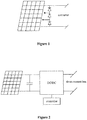
- Figure 1 shows an example of a conventional photovoltaic module.
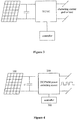
- Figure 2 is a schematic diagram of a direct current modular photovoltaic module.
- the direct current modular photovoltaic module includes a conventional photovoltaic module, a DC/DC power switching circuit and a controller.
- the direct current modular photovoltaic module outputs direct current power and can realize the maximum power point tracking (MPPT).
- MPPT maximum power point tracking
- the direct current modular photovoltaic module outputs a direct current voltage, which may be employed alone as a direct current bus, or may be connected in series to form a higher voltage direct current bus.
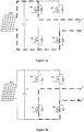
- Figure 3 is a schematic diagram of an alternating current modular photovoltaic module.
- the alternating current modular photovoltaic module includes a conventional photovoltaic module, a DC/AC power switching circuit and a controller.
- the alternating current modular photovoltaic module outputs alternating current power and can be connected with the grid directly or supply power to an alternating current load directly.
- US 6282111 B1 discloses a DC to AC inverter used in a photovoltaic system including solar panels, the invert includes a DC-PWM power switching circuit and a controller, the controller comprises a low voltage reference sine wave generator 101. It also discloses that if the low voltage reference sine wave generator 101 is replaced by a DC voltage reference, the same circuit configuration may construct a DC to DC converter.
- Document US2011/267855A1 discloses an apparatus, device, and system for generating an amount of output power in response to a direct current (DC) power input includes a configurable power supply, which may be electrically coupled to the DC power input.
- the configurable power supply is selectively configurable between multiple circuit topologies to generate various DC power outputs and/or and AC power output.
- the system may also include one or more DC power electronic accessories, such as DC-to-DC power converters, and/or one or more AC power electronic accessories such as DC-to-AC power converters.
- the power electronic accessories are couplable to the configurable power supply to receive the corresponding DC or AC power output of the configurable power supply.
- the present disclosure provides an alternating-current direct-current (AC-DC) photovoltaic device which can be controlled to output either of alternating current power and direct current power, according to independent claim 1, which is of high flexibility and versatility and can be adapted to a diversity of photovoltaic applications in the future.
- AC-DC alternating-current direct-current
- An embodiment of the present disclosure provides an AC-DC photovoltaic device, including: a photovoltaic module, a direct current side capacitor, a direct current pulse width modulation (DC-PWM) power switching circuit, and a controller; the direct current side capacitor is connected in parallel with an output terminal of the photovoltaic module; an input terminal of the DC-PWM power switching circuit is connected with the output terminal of the photovoltaic module; the DC-PWM power switching circuit is a full-bridge circuit, the full-bridge circuit comprises four controllable switch transistors S1, S2 S3 and S3, wherein the controllable switch transistors S1 and S3 are connected in series, the controllable switch transistors S2 and S4 are connected in series, and the series of the controllable switch transistors S1 and S3 and the series of the controllable switch transistors S2 and S4 are connected in parallel with the output terminal of the photovoltaic module, a point between the controllable switch transistors S1 and S3 and a point between the controllable switch transistors
- the input terminal of the DC-PWM power switching circuit is directly connected with an output terminal of photovoltaic module; and the controller is configured to monitor a status of photovoltaic module and to realize a maximum power point tracking.
- the DC-PWM power switching circuit is a full-bridge circuit.
- the DC-PWM power switching circuit is a three-level inverter topology circuit.
- the AC-DC photovoltaic device supplies power to a load, where the load is a direct current motor or a Light Emitting Diode (LED) streetlamp.
- the load is a direct current motor or a Light Emitting Diode (LED) streetlamp.
- a system includes multiple AC-DC photovoltaic devices, in a case that the DC-PWM power switching circuit outputs the direct current PWM wave; multiple said AC-DC photovoltaic devices are connected in series to supply power to a high-voltage direct current communication system.
- the DC-PWM power switching circuit outputs the direct current PWM wave
- multiple said AC-DC photovoltaic devices are connected in series or in series-parallel, and then connected with an input terminal of an inverter, an output terminal of the inverter is connected with the alternating current grid.
- the AC-PWM power switching circuit outputs an alternating current PWM wave; and multiple said AC-DC photovoltaic devices are connected in series to supply power to a household appliance, or connected in series and then connected with an alternating current grid, or connected in series-parallel and then connected with an alternating current grid.
- the text processing device further includes: a filter circuit.
- the filter circuit is configured to filter a harmonic component out of the direct current PWM wave or the alternating current PWM wave outputted from the DC-PWM power switching circuit.
- the DC-PWM power switching circuit is controlled to output a direct current PWM wave or an alternating current PWM wave, by the switch control signal outputted by the controller.
- the switch control signal is a direct current modulation signal
- the DC-PWM power switching circuit outputs the direct current PWM wave
- the switch control signal is an alternating current modulation signal
- the DC-PWM power switching circuit outputs the alternating current PWM wave. Therefore the photovoltaic device can be applied to both direct current power supply occasions and alternating current power supply occasions, thus improving the versatility of the photovoltaic device.
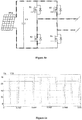
- Figure 4 is a schematic diagram of an AC-DC photovoltaic device according to a first embodiment of the present disclosure.
- the AC-DC photovoltaic device includes: a photovoltaic module 100, a direct current side capacitor C, a direct current pulse width modulation (DC-PWM) power switching circuit 200, and a controller 300.
- a photovoltaic module 100 a direct current side capacitor C
- a direct current pulse width modulation (DC-PWM) power switching circuit 200 a controller 300.
- the direct current side capacitor C is connected in parallel with an output terminal of the photovoltaic module 100.
- An input terminal of the DC-PWM power switching circuit 200 is connected with the output terminal of the photovoltaic module.
- the DC-PWM power switching circuit 200 includes a controllable switch transistor.
- the controller 300 is configured to output a switch control signal to control a switching state of the controllable switch transistor in the DC-PWM power switching circuit 200, to control the DC-PWM power switching circuit 200 to output a direct current PWM wave or an alternating current PWM wave.
- the switch control signal is a direct current modulation signal
- the DC-PWM power switching circuit outputs the direct current PWM wave.
- the switch control signal is an alternating current modulation signal
- the DC-PWM power switching circuit outputs the alternating current PWM wave.
- the direct current PWM wave includes a direct current modulation component and a harmonic component.
- the alternating current PWM wave includes an alternating current modulation component and a harmonic component.
- an objective of the present disclosure is to control the photovoltaic module to output direct current power in a case of a load requiring direct current power, and output alternating current power in a case of a load requiring alternating current power.
- the switch control signal is a direct current modulation signal
- a direct current PWM wave is outputted, which includes a direct current modulation component and a harmonic component. Only the direct current component is left after filtering.
- the photovoltaic module 100 may include multiple photovoltaic panels connected in series, or multiple photovoltaic panels connected in parallel, or multiple photovoltaic panels connected in series-parallel.
- the photovoltaic module 100 outputs direct current power and the DC-PWM power switching circuit 200 may convert the direct current power into a PWM wave signal for output.
- controller 300 may not only output the switch control signal, but also perform other controls, such as monitoring a status of the photovoltaic module or a photovoltaic panel, realizing the maximum power point tracking (MPPT), and performing functions of protection, communication and the like.
- MPPT maximum power point tracking
- the controller 300 may be implemented in the form of an MCU or a DSP, etc.
- the DC-PWM power switching circuit is controlled to output a direct current PWM wave or an alternating current PWM wave, by the switch control signal outputted by the controller.
- the switch control signal is a direct current modulation signal
- the DC-PWM power switching circuit outputs the direct current PWM wave.
- the switch control signal is an alternating current modulation signal
- the DC-PWM power switching circuit outputs the alternating current PWM wave. Therefore the photovoltaic device can be applied to both direct current power supply occasions and alternating current power supply occasions, thus improving the versatility of the photovoltaic device.
- Figures 5a to 5c are schematic diagrams of an AC-DC photovoltaic device according to a second embodiment of the present disclosure.
- the present embodiment is described with an example that the DC-PWM power switching circuit is implemented by a full-bridge circuit.
- the full-bridge circuit includes four controllable switch transistors S1 to S4. By controlling switching states of the four controllable switch transistors, the full-bridge circuit is controlled to output different levels.
- levels of +1, 0 and -1 may be generated.
- Figure 5a shows that a level +1 is generated in a case that S1 and S4 are on while S2 and S3 are off in a full H-bridge circuit.
- Figure 5b shows that a level 0 is generated in a case that S3 and S4 are on while S1 and S2 are off in a full H-bridge circuit. It should be noted that in the full H-bridge circuit, the level 0 is also generated in a case that S3 and S4 are off while S1 and S2 are on, which is not illustrated.
- Figure 5c shows that a level -1 is generated in a case that S2 and S3 are on while S1 and S4 are off in a full H-bridge circuit.
- the PWM wave is a pulse width signal which includes at least two of the three levels of +1, 0 and -1.
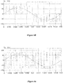
- Figures 6a to 6e show PWM waveforms in which the modulation wave include levels of +1, 0 and -1.
- Figure 6a shows a PWM waveform in a case that a switch control signal is a positive direct current quantity, which includes two levels of +1 and 0.
- Figure 6b shows a PWM waveform in a case that a switch control signal is a negative direct current quantity, which includes two levels of -1 and 0.
- Figure 6c shows a PWM waveform in a case that a switch control signal is a positive direct current quantity, which includes two levels of +1 and -1.
- Figure 6d shows a PWM waveform in a case that a switch control signal is a unipolar sinusoidal quantity, which includes three levels of +1, 0 and -1.
- Figure 6e shows a PWM waveform in a case that a switch control signal is a unipolar sinusoidal quantity, which includes two levels of +1 and-1.
- the DC-PWM power switching circuit is a full-bridge circuit. Understandably, the DC-PWM power switching circuit may also be implemented by a derivative circuit of the full-bridge circuit.
- a derivative multi-level topology can be implemented by a three-level single-phase inverter circuit as shown in Figure 7 .
- the AC-DC photovoltaic device is highly versatile and can be applied to both direct current power supply occasions and alternating current power supply occasions.
- the applications of the AC-DC photovoltaic device is described in detail in conjunction with the drawings.
- Figure 8a shows that the load is a direct current motor M in a case that the AC-DC photovoltaic device is configured to output a direct current PWM wave, that is, the device supplies power to M.
- Figure 8b shows that the load is a direct current LED lamp in a case that the AC-DC photovoltaic device is configured to output a direct current PWM wave, that is, the device supplies power to the LED lamp.
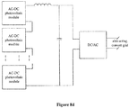
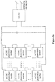
- the multiple photovoltaic devices are connected in series and then connected with a DC/AC input terminal of an inverter, and an output terminal of the inverter is connected with the alternating current grid.
- Figure 8d the difference between Figure 8d and Figure 8e lies in that the multiple photovoltaic devices in Figure 8d are connected in series to increase the output voltage, while the multiple photovoltaic devices in Figure 8e are connected in series-parallel to increase both the output voltage and the output current.
- FIG. 8f in which there are multiple photovoltaic devices.
- the DC-PWM power switching circuit is configured to output an alternating current PWM wave
- the multiple photovoltaic devices are connected in series to supply power to a household appliance.
- FIG. 8g in which there are multiple photovoltaic devices.
- the DC-PWM power switching circuit is configured to output an alternating current PWM wave
- the multiple photovoltaic devices are connected in series and then connected with the alternating current grid.
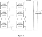
- FIG. 8h in which there are multiple photovoltaic device.
- the DC-PWM power switching circuit is configured to output an alternating current PWM wave
- the multiple photovoltaic devices are connected in series-parallel and then connected with the alternating current grid.
- the AC-DC photovoltaic device may be applied to various occasions.
- the DC-PWM power switching circuit is controlled by the controller to convert direct current power into a series of PWM waves.
- the filters circuit filters the harmonic components out of the direct current PWM waves or alternating current PWM wave outputted by the AC-DC photovoltaic device, various voltage waveforms such as direct current waveforms or sinusoidal alternating current waveforms can be generated.
Landscapes
- Engineering & Computer Science (AREA)
- Power Engineering (AREA)
- General Engineering & Computer Science (AREA)
- Inverter Devices (AREA)
- Dc-Dc Converters (AREA)
Claims (9)
- Dispositif photovoltaïque à courant alternatif-courant continu (CA-CC), comprenant :un module photovoltaïque,un condensateur côté courant continu,un circuit de commutation de puissance de modulation de largeur d'impulsion à courant continu (CC-PWM), etune unité de commande, dans laquellele condensateur côté courant continu est connecté en parallèle avec une borne de sortie du module photovoltaïque ;une borne d'entrée du circuit de commutation de puissance CC-PWM est connectée à la borne de sortie du module photovoltaïque ;caractérisé en ce que :le circuit de commutation de puissance CC-PWM est un circuit en pont complet, le circuit en pont complet comprend quatre transistors de commutation commandables S1, S2 S3 et S3, dans lequel les transistors de commutation commandables S1 et S3 sont connectés en série, les transistors de commutation commandables S2 et S4 sont connectés en série, et la série des transistors de commutation commandables S1 et S3 et la série des transistors de commutation commandables S2 et S4 sont connectées en parallèle avec la borne de sortie du module photovoltaïque ; un point entre les transistors de commutation commandables S1 et S3 et un point entre les transistors de commutation commandables S2 et S4 constituent une sortie du circuit de commutation de puissance CC-PWM ;l'unité de commande est configurée pour émettre un signal de commande de commutation pour commander un état de commutation du transistor de commutation commandable dans le circuit de commutation de puissance CC-PWM, pour commander le circuit de commutation de puissance CC-PWM pour émettre à partir de la sortie du circuit de commutation de puissance CC-PWM une onde à courant continu PWM dans le cas où le signal de commande de commutation est un signal de modulation à courant continu et émettre à partir de la sortie du circuit de commutation de puissance CC-PWM une onde à courant alternatif PWM dans le cas où le signal de commande de commutation est un signal de modulation à courant alternatif.
- Dispositif photovoltaïque CA-CC selon la revendication 1, dans lequel la borne d'entrée du circuit de commutation de puissance CC-PWM est connectée directement à une borne de sortie du module photovoltaïque ; et l'unité de commande est configurée pour surveiller un état du module photovoltaïque et pour mettre en œuvre un suivi de point de puissance maximum.
- Dispositif photovoltaïque CA-CC selon la revendication 2, dans lequel le circuit de commutation de puissance CC-PWM est un circuit en pont complet.
- Dispositif photovoltaïque CA-CC selon la revendication 2, dans lequel le circuit de commutation de puissance CC-PWM est un circuit topologique d'onduleur à trois niveaux.
- Dispositif photovoltaïque CA-CC selon l'une quelconque de revendications 1 à 4, dans lequel dans le cas où le circuit de commutation de puissance CC-PWM émet l'onde à courant continu PWM, le dispositif photovoltaïque CA-CC fournit de la puissance à une charge, la charge étant un moteur à courant continu ou un réverbère à diode électroluminescente (DEL).
- Système comprenant une pluralité des dispositifs photovoltaïques CA-CC selon une quelconque des revendications 1 à 4, dans lequel dans le cas où le circuit de commutation de puissance CD-PWM émet l'onde de courant continu PWM :
la pluralité des dispositifs photovoltaïques CA-CC sont connectés en série pour fournir de la puissance à un système de communication à courant continu haute tension. - Système comprenant une pluralité des dispositifs photovoltaïques CA-CC selon une quelconque des revendications 1 à 4, dans lequel dans le cas où le circuit de commutation de puissance CD-PWM émet l'onde de courant continu PWM : la pluralité des dispositifs photovoltaïques CA-CC sont connectés en série ou en série-parallèle, et ensuite connectés à une borne d'entrée d'un onduleur, une borne de sortie de l'onduleur est connectée à un réseau à courant alternatif.
- Système comprenant une pluralité des dispositifs photovoltaïques CA-CC selon une quelconque des revendications 1 à 4, dans lequel dans le cas où le circuit de commutation de puissance CD-PWM émet l'onde de courant alternatif PWM :
la pluralité des dispositifs photovoltaïques CA-CC sont connectés en série pour fournir de la puissance à un appareil ménager, ou connectés en série et ensuite connectés à un réseau à courant alternatif ou connectés en série-parallèle et ensuite connectés à un réseau à courant alternatif. - Dispositif photovoltaïques CA-CC selon la revendication 1, comprenant en outre : un circuit de filtrage, configuré pour filtrer une composante harmonique hors de l'onde de courant continu PWM ou de l'onde de courant alternatif PWM émise par le circuit de commutation de puissance CC-PWM.
Applications Claiming Priority (1)
| Application Number | Priority Date | Filing Date | Title |
|---|---|---|---|
| CN201610305675.6A CN107359855B (zh) | 2016-05-09 | 2016-05-09 | 一种交直流两用的光伏设备 |
Publications (2)
| Publication Number | Publication Date |
|---|---|
| EP3244523A1 EP3244523A1 (fr) | 2017-11-15 |
| EP3244523B1 true EP3244523B1 (fr) | 2020-11-25 |
Family
ID=58448465
Family Applications (1)
| Application Number | Title | Priority Date | Filing Date |
|---|---|---|---|
| EP17163347.2A Active EP3244523B1 (fr) | 2016-05-09 | 2017-03-28 | Dispositif photovoltaïque courant alternatif-courant continu |
Country Status (5)
| Country | Link |
|---|---|
| US (1) | US10389132B2 (fr) |
| EP (1) | EP3244523B1 (fr) |
| JP (1) | JP2017205003A (fr) |
| CN (1) | CN107359855B (fr) |
| ES (1) | ES2854927T3 (fr) |
Families Citing this family (8)
| Publication number | Priority date | Publication date | Assignee | Title |
|---|---|---|---|---|
| US10673246B2 (en) * | 2017-11-13 | 2020-06-02 | Futurewei Technologies, Inc. | System and device for exporting power, and method of configuring thereof |
| CN108199602B (zh) * | 2018-01-09 | 2020-10-30 | 青岛大学 | 多绕组分时供电正激直流斩波型单级多输入高频链逆变器 |
| US10516365B1 (en) | 2018-06-20 | 2019-12-24 | Schneider Electric Solar Inverters Usa, Inc. | DC voltage control in renewable energy based multilevel power converter |
| CN110492580B (zh) * | 2019-09-16 | 2022-04-08 | 阳光电源股份有限公司 | 直流充电系统控制方法、直流充电系统及控制器 |
| US11682963B1 (en) * | 2022-03-21 | 2023-06-20 | United States Of America As Represented By The Secretary Of The Navy | Current combination system |
| EP4478592A1 (fr) * | 2023-06-13 | 2024-12-18 | FRONIUS INTERNATIONAL GmbH | Convertisseur de puissance et procédé de fonctionnement d'un convertisseur de puissance |
| CN119743034B (zh) * | 2024-12-24 | 2025-10-17 | 广东工业大学 | 基于液晶模组的多电平光子逆变器及其逆变方法 |
| CN119743035B (zh) * | 2024-12-24 | 2025-10-17 | 广东工业大学 | 一种多电平dc-ac光子电能变换器及其变流调制方法 |
Citations (2)
| Publication number | Priority date | Publication date | Assignee | Title |
|---|---|---|---|---|
| US20110267855A1 (en) * | 2011-04-27 | 2011-11-03 | Patrick Chapman | Modular photovoltaic power supply assembly |
| WO2013107782A2 (fr) * | 2012-01-17 | 2013-07-25 | Infineon Technologies Austria Ag | Circuit convertisseur de puissance, système et procédé d'alimentation |
Family Cites Families (14)
| Publication number | Priority date | Publication date | Assignee | Title |
|---|---|---|---|---|
| JPH09135583A (ja) * | 1995-11-07 | 1997-05-20 | Japan Storage Battery Co Ltd | 太陽光発電用インバ−タ |
| JP2000050638A (ja) * | 1998-07-27 | 2000-02-18 | Ebara Densan Ltd | 任意波形出力電源装置 |
| US6282111B1 (en) * | 1999-06-18 | 2001-08-28 | Avionic Instruments Inc | Inverter control using current mode slope modulation |
| JP2003088130A (ja) | 2001-09-07 | 2003-03-20 | Matsushita Electric Ind Co Ltd | バッテリ内蔵型電力変換装置 |
| JP2004201394A (ja) * | 2002-12-17 | 2004-07-15 | Canon Inc | 電力変換装置 |
| US8816535B2 (en) * | 2007-10-10 | 2014-08-26 | Solaredge Technologies, Ltd. | System and method for protection during inverter shutdown in distributed power installations |
| JP2012060735A (ja) * | 2010-09-07 | 2012-03-22 | Sharp Corp | マルチレベルインバータ |
| GB2483317B (en) | 2011-01-12 | 2012-08-22 | Solaredge Technologies Ltd | Serially connected inverters |
| WO2013080469A1 (fr) * | 2011-11-29 | 2013-06-06 | パナソニック 株式会社 | Dispositif de conversion électrique |
| ES2881925T3 (es) * | 2013-03-15 | 2021-11-30 | Ampt Llc | Sistema de alimentación solar intercambiable de alta eficiencia |
| JP2015053817A (ja) * | 2013-09-09 | 2015-03-19 | 株式会社日立製作所 | 電力変換装置 |
| US9906038B2 (en) * | 2015-01-29 | 2018-02-27 | Cyboenergy, Inc. | Smart renewable power generation system with grid and DC source flexibility |
| JP6646852B2 (ja) * | 2016-01-28 | 2020-02-14 | パナソニックIpマネジメント株式会社 | 電力変換装置、及び電力変換システム |
| US10141829B2 (en) * | 2016-06-29 | 2018-11-27 | John Bean Technologies Corporation | Multiple power topologies from single power generator |
-
2016
- 2016-05-09 CN CN201610305675.6A patent/CN107359855B/zh active Active
-
2017
- 2017-03-28 ES ES17163347T patent/ES2854927T3/es active Active
- 2017-03-28 EP EP17163347.2A patent/EP3244523B1/fr active Active
- 2017-03-30 US US15/474,061 patent/US10389132B2/en active Active
- 2017-03-30 JP JP2017067017A patent/JP2017205003A/ja active Pending
Patent Citations (2)
| Publication number | Priority date | Publication date | Assignee | Title |
|---|---|---|---|---|
| US20110267855A1 (en) * | 2011-04-27 | 2011-11-03 | Patrick Chapman | Modular photovoltaic power supply assembly |
| WO2013107782A2 (fr) * | 2012-01-17 | 2013-07-25 | Infineon Technologies Austria Ag | Circuit convertisseur de puissance, système et procédé d'alimentation |
Also Published As
| Publication number | Publication date |
|---|---|
| US10389132B2 (en) | 2019-08-20 |
| US20170324249A1 (en) | 2017-11-09 |
| EP3244523A1 (fr) | 2017-11-15 |
| JP2017205003A (ja) | 2017-11-16 |
| ES2854927T3 (es) | 2021-09-23 |
| CN107359855A (zh) | 2017-11-17 |
| CN107359855B (zh) | 2020-01-21 |
Similar Documents
| Publication | Publication Date | Title |
|---|---|---|
| EP3244523B1 (fr) | Dispositif photovoltaïque courant alternatif-courant continu | |
| US11005388B2 (en) | Single-phase multi-level asymmetric inverter with AC-bypass and asymmetric modulation strategy | |
| US8378656B2 (en) | Quasi-AC, photovoltaic module for unfolder photovoltaic inverter | |
| AU2019262602B2 (en) | Systems and methods of DC power conversion and transmission for solar fields | |
| Siwakoti et al. | A novel flying capacitor transformerless inverter for single-phase grid connected solar photovoltaic system | |
| Siwakoti et al. | H-Bridge transformerless inverter with common ground for single-phase solar-photovoltaic system | |
| CN107005059A (zh) | 一种电流源逆变器系统及逆变装置 | |
| KR20150098103A (ko) | 전력변환장치 및 태양광 모듈 | |
| KR20160129265A (ko) | 태양광 컨버터 및 에너지 저장 컨버터를 이용한 계통 연계형 통합 장치 | |
| Hasan et al. | Common-ground transformerless inverter for solar photovoltaic module | |
| JP2017511103A (ja) | 電力変換電子機器 | |
| CN115776218B (zh) | 一种大功率高压直流纹波电源 | |
| WO2024145954A1 (fr) | Onduleur photovoltaïque et procédé de commande de puissance | |
| Roncero-Clemente et al. | Interleaved single-phase quasi-Z-source inverter with special modulation technique | |
| WO2016004896A1 (fr) | Onduleur photovoltaïque et climatiseur | |
| KR20150085411A (ko) | 전력변환장치 및 태양광 모듈 | |
| JP7715820B2 (ja) | 太陽光発電インバータ及び電力制御方法 | |
| CN107979299B (zh) | 一种三相电流源逆变器 | |
| KR20150086765A (ko) | 전력변환장치 및 태양광 모듈 | |
| Kashif et al. | A multilevel inverter topology with reduced number of switches | |
| Srinithi et al. | Symmetric multilevel inverter using DC-DC zeta converter | |
| CN107579675A (zh) | 一种可抑制漏电流六开关电流型光伏逆变器拓扑及方法 | |
| WO2013098844A2 (fr) | Onduleur réseau | |
| CN107565676B (zh) | 一种光伏设备及光伏系统 | |
| Kiran et al. | High-Efficiency Buck-Boost Inverter Architecture for Transformer-Less Solar PV Grid Integration |
Legal Events
| Date | Code | Title | Description |
|---|---|---|---|
| PUAI | Public reference made under article 153(3) epc to a published international application that has entered the european phase |
Free format text: ORIGINAL CODE: 0009012 |
|
| STAA | Information on the status of an ep patent application or granted ep patent |
Free format text: STATUS: THE APPLICATION HAS BEEN PUBLISHED |
|
| AK | Designated contracting states |
Kind code of ref document: A1 Designated state(s): AL AT BE BG CH CY CZ DE DK EE ES FI FR GB GR HR HU IE IS IT LI LT LU LV MC MK MT NL NO PL PT RO RS SE SI SK SM TR |
|
| AX | Request for extension of the european patent |
Extension state: BA ME |
|
| STAA | Information on the status of an ep patent application or granted ep patent |
Free format text: STATUS: REQUEST FOR EXAMINATION WAS MADE |
|
| 17P | Request for examination filed |
Effective date: 20180515 |
|
| RBV | Designated contracting states (corrected) |
Designated state(s): AL AT BE BG CH CY CZ DE DK EE ES FI FR GB GR HR HU IE IS IT LI LT LU LV MC MK MT NL NO PL PT RO RS SE SI SK SM TR |
|
| STAA | Information on the status of an ep patent application or granted ep patent |
Free format text: STATUS: EXAMINATION IS IN PROGRESS |
|
| 17Q | First examination report despatched |
Effective date: 20190619 |
|
| GRAP | Despatch of communication of intention to grant a patent |
Free format text: ORIGINAL CODE: EPIDOSNIGR1 |
|
| STAA | Information on the status of an ep patent application or granted ep patent |
Free format text: STATUS: GRANT OF PATENT IS INTENDED |
|
| INTG | Intention to grant announced |
Effective date: 20200618 |
|
| RIN1 | Information on inventor provided before grant (corrected) |
Inventor name: GU, YILEI Inventor name: CAO, RENXIAN Inventor name: GU, YU Inventor name: XU, JUN |
|
| GRAS | Grant fee paid |
Free format text: ORIGINAL CODE: EPIDOSNIGR3 |
|
| GRAA | (expected) grant |
Free format text: ORIGINAL CODE: 0009210 |
|
| STAA | Information on the status of an ep patent application or granted ep patent |
Free format text: STATUS: THE PATENT HAS BEEN GRANTED |
|
| AK | Designated contracting states |
Kind code of ref document: B1 Designated state(s): AL AT BE BG CH CY CZ DE DK EE ES FI FR GB GR HR HU IE IS IT LI LT LU LV MC MK MT NL NO PL PT RO RS SE SI SK SM TR |
|
| REG | Reference to a national code |
Ref country code: GB Ref legal event code: FG4D |
|
| REG | Reference to a national code |
Ref country code: CH Ref legal event code: EP |
|
| REG | Reference to a national code |
Ref country code: AT Ref legal event code: REF Ref document number: 1339429 Country of ref document: AT Kind code of ref document: T Effective date: 20201215 |
|
| REG | Reference to a national code |
Ref country code: DE Ref legal event code: R096 Ref document number: 602017028071 Country of ref document: DE |
|
| REG | Reference to a national code |
Ref country code: IE Ref legal event code: FG4D |
|
| REG | Reference to a national code |
Ref country code: AT Ref legal event code: MK05 Ref document number: 1339429 Country of ref document: AT Kind code of ref document: T Effective date: 20201125 |
|
| REG | Reference to a national code |
Ref country code: GR Ref legal event code: EP Ref document number: 20210400437 Country of ref document: GR Effective date: 20210416 |
|
| REG | Reference to a national code |
Ref country code: NL Ref legal event code: MP Effective date: 20201125 |
|
| PG25 | Lapsed in a contracting state [announced via postgrant information from national office to epo] |
Ref country code: NO Free format text: LAPSE BECAUSE OF FAILURE TO SUBMIT A TRANSLATION OF THE DESCRIPTION OR TO PAY THE FEE WITHIN THE PRESCRIBED TIME-LIMIT Effective date: 20210225 Ref country code: RS Free format text: LAPSE BECAUSE OF FAILURE TO SUBMIT A TRANSLATION OF THE DESCRIPTION OR TO PAY THE FEE WITHIN THE PRESCRIBED TIME-LIMIT Effective date: 20201125 Ref country code: PT Free format text: LAPSE BECAUSE OF FAILURE TO SUBMIT A TRANSLATION OF THE DESCRIPTION OR TO PAY THE FEE WITHIN THE PRESCRIBED TIME-LIMIT Effective date: 20210325 Ref country code: FI Free format text: LAPSE BECAUSE OF FAILURE TO SUBMIT A TRANSLATION OF THE DESCRIPTION OR TO PAY THE FEE WITHIN THE PRESCRIBED TIME-LIMIT Effective date: 20201125 |
|
| PG25 | Lapsed in a contracting state [announced via postgrant information from national office to epo] |
Ref country code: AT Free format text: LAPSE BECAUSE OF FAILURE TO SUBMIT A TRANSLATION OF THE DESCRIPTION OR TO PAY THE FEE WITHIN THE PRESCRIBED TIME-LIMIT Effective date: 20201125 Ref country code: BG Free format text: LAPSE BECAUSE OF FAILURE TO SUBMIT A TRANSLATION OF THE DESCRIPTION OR TO PAY THE FEE WITHIN THE PRESCRIBED TIME-LIMIT Effective date: 20210225 Ref country code: LV Free format text: LAPSE BECAUSE OF FAILURE TO SUBMIT A TRANSLATION OF THE DESCRIPTION OR TO PAY THE FEE WITHIN THE PRESCRIBED TIME-LIMIT Effective date: 20201125 Ref country code: PL Free format text: LAPSE BECAUSE OF FAILURE TO SUBMIT A TRANSLATION OF THE DESCRIPTION OR TO PAY THE FEE WITHIN THE PRESCRIBED TIME-LIMIT Effective date: 20201125 Ref country code: IS Free format text: LAPSE BECAUSE OF FAILURE TO SUBMIT A TRANSLATION OF THE DESCRIPTION OR TO PAY THE FEE WITHIN THE PRESCRIBED TIME-LIMIT Effective date: 20210325 Ref country code: SE Free format text: LAPSE BECAUSE OF FAILURE TO SUBMIT A TRANSLATION OF THE DESCRIPTION OR TO PAY THE FEE WITHIN THE PRESCRIBED TIME-LIMIT Effective date: 20201125 |
|
| REG | Reference to a national code |
Ref country code: LT Ref legal event code: MG9D |
|
| PG25 | Lapsed in a contracting state [announced via postgrant information from national office to epo] |
Ref country code: HR Free format text: LAPSE BECAUSE OF FAILURE TO SUBMIT A TRANSLATION OF THE DESCRIPTION OR TO PAY THE FEE WITHIN THE PRESCRIBED TIME-LIMIT Effective date: 20201125 |
|
| PG25 | Lapsed in a contracting state [announced via postgrant information from national office to epo] |
Ref country code: RO Free format text: LAPSE BECAUSE OF FAILURE TO SUBMIT A TRANSLATION OF THE DESCRIPTION OR TO PAY THE FEE WITHIN THE PRESCRIBED TIME-LIMIT Effective date: 20201125 Ref country code: SK Free format text: LAPSE BECAUSE OF FAILURE TO SUBMIT A TRANSLATION OF THE DESCRIPTION OR TO PAY THE FEE WITHIN THE PRESCRIBED TIME-LIMIT Effective date: 20201125 Ref country code: EE Free format text: LAPSE BECAUSE OF FAILURE TO SUBMIT A TRANSLATION OF THE DESCRIPTION OR TO PAY THE FEE WITHIN THE PRESCRIBED TIME-LIMIT Effective date: 20201125 Ref country code: CZ Free format text: LAPSE BECAUSE OF FAILURE TO SUBMIT A TRANSLATION OF THE DESCRIPTION OR TO PAY THE FEE WITHIN THE PRESCRIBED TIME-LIMIT Effective date: 20201125 Ref country code: SM Free format text: LAPSE BECAUSE OF FAILURE TO SUBMIT A TRANSLATION OF THE DESCRIPTION OR TO PAY THE FEE WITHIN THE PRESCRIBED TIME-LIMIT Effective date: 20201125 Ref country code: LT Free format text: LAPSE BECAUSE OF FAILURE TO SUBMIT A TRANSLATION OF THE DESCRIPTION OR TO PAY THE FEE WITHIN THE PRESCRIBED TIME-LIMIT Effective date: 20201125 |
|
| REG | Reference to a national code |
Ref country code: DE Ref legal event code: R097 Ref document number: 602017028071 Country of ref document: DE |
|
| PG25 | Lapsed in a contracting state [announced via postgrant information from national office to epo] |
Ref country code: DK Free format text: LAPSE BECAUSE OF FAILURE TO SUBMIT A TRANSLATION OF THE DESCRIPTION OR TO PAY THE FEE WITHIN THE PRESCRIBED TIME-LIMIT Effective date: 20201125 |
|
| REG | Reference to a national code |
Ref country code: ES Ref legal event code: FG2A Ref document number: 2854927 Country of ref document: ES Kind code of ref document: T3 Effective date: 20210923 |
|
| PLBE | No opposition filed within time limit |
Free format text: ORIGINAL CODE: 0009261 |
|
| STAA | Information on the status of an ep patent application or granted ep patent |
Free format text: STATUS: NO OPPOSITION FILED WITHIN TIME LIMIT |
|
| PG25 | Lapsed in a contracting state [announced via postgrant information from national office to epo] |
Ref country code: AL Free format text: LAPSE BECAUSE OF FAILURE TO SUBMIT A TRANSLATION OF THE DESCRIPTION OR TO PAY THE FEE WITHIN THE PRESCRIBED TIME-LIMIT Effective date: 20201125 Ref country code: NL Free format text: LAPSE BECAUSE OF FAILURE TO SUBMIT A TRANSLATION OF THE DESCRIPTION OR TO PAY THE FEE WITHIN THE PRESCRIBED TIME-LIMIT Effective date: 20201125 Ref country code: MC Free format text: LAPSE BECAUSE OF FAILURE TO SUBMIT A TRANSLATION OF THE DESCRIPTION OR TO PAY THE FEE WITHIN THE PRESCRIBED TIME-LIMIT Effective date: 20201125 |
|
| REG | Reference to a national code |
Ref country code: CH Ref legal event code: PL |
|
| 26N | No opposition filed |
Effective date: 20210826 |
|
| GBPC | Gb: european patent ceased through non-payment of renewal fee |
Effective date: 20210328 |
|
| PG25 | Lapsed in a contracting state [announced via postgrant information from national office to epo] |
Ref country code: SI Free format text: LAPSE BECAUSE OF FAILURE TO SUBMIT A TRANSLATION OF THE DESCRIPTION OR TO PAY THE FEE WITHIN THE PRESCRIBED TIME-LIMIT Effective date: 20201125 |
|
| REG | Reference to a national code |
Ref country code: BE Ref legal event code: MM Effective date: 20210331 |
|
| PG25 | Lapsed in a contracting state [announced via postgrant information from national office to epo] |
Ref country code: GB Free format text: LAPSE BECAUSE OF NON-PAYMENT OF DUE FEES Effective date: 20210328 Ref country code: LI Free format text: LAPSE BECAUSE OF NON-PAYMENT OF DUE FEES Effective date: 20210331 Ref country code: LU Free format text: LAPSE BECAUSE OF NON-PAYMENT OF DUE FEES Effective date: 20210328 Ref country code: CH Free format text: LAPSE BECAUSE OF NON-PAYMENT OF DUE FEES Effective date: 20210331 Ref country code: IE Free format text: LAPSE BECAUSE OF NON-PAYMENT OF DUE FEES Effective date: 20210328 |
|
| REG | Reference to a national code |
Ref country code: DE Ref legal event code: R082 Representative=s name: ZACCO LEGAL RECHTSANWALTSGESELLSCHAFT MBH, DE Ref document number: 602017028071 Country of ref document: DE |
|
| PG25 | Lapsed in a contracting state [announced via postgrant information from national office to epo] |
Ref country code: IS Free format text: LAPSE BECAUSE OF FAILURE TO SUBMIT A TRANSLATION OF THE DESCRIPTION OR TO PAY THE FEE WITHIN THE PRESCRIBED TIME-LIMIT Effective date: 20210325 |
|
| PG25 | Lapsed in a contracting state [announced via postgrant information from national office to epo] |
Ref country code: BE Free format text: LAPSE BECAUSE OF NON-PAYMENT OF DUE FEES Effective date: 20210331 |
|
| PG25 | Lapsed in a contracting state [announced via postgrant information from national office to epo] |
Ref country code: HU Free format text: LAPSE BECAUSE OF FAILURE TO SUBMIT A TRANSLATION OF THE DESCRIPTION OR TO PAY THE FEE WITHIN THE PRESCRIBED TIME-LIMIT; INVALID AB INITIO Effective date: 20170328 |
|
| P01 | Opt-out of the competence of the unified patent court (upc) registered |
Effective date: 20230426 |
|
| PG25 | Lapsed in a contracting state [announced via postgrant information from national office to epo] |
Ref country code: CY Free format text: LAPSE BECAUSE OF FAILURE TO SUBMIT A TRANSLATION OF THE DESCRIPTION OR TO PAY THE FEE WITHIN THE PRESCRIBED TIME-LIMIT Effective date: 20201125 |
|
| PG25 | Lapsed in a contracting state [announced via postgrant information from national office to epo] |
Ref country code: MK Free format text: LAPSE BECAUSE OF FAILURE TO SUBMIT A TRANSLATION OF THE DESCRIPTION OR TO PAY THE FEE WITHIN THE PRESCRIBED TIME-LIMIT Effective date: 20201125 |
|
| PG25 | Lapsed in a contracting state [announced via postgrant information from national office to epo] |
Ref country code: MT Free format text: LAPSE BECAUSE OF FAILURE TO SUBMIT A TRANSLATION OF THE DESCRIPTION OR TO PAY THE FEE WITHIN THE PRESCRIBED TIME-LIMIT Effective date: 20201125 |
|
| PGFP | Annual fee paid to national office [announced via postgrant information from national office to epo] |
Ref country code: ES Payment date: 20250505 Year of fee payment: 9 |
|
| REG | Reference to a national code |
Ref country code: DE Ref legal event code: R082 Ref document number: 602017028071 Country of ref document: DE |
|
| PG25 | Lapsed in a contracting state [announced via postgrant information from national office to epo] |
Ref country code: TR Free format text: LAPSE BECAUSE OF FAILURE TO SUBMIT A TRANSLATION OF THE DESCRIPTION OR TO PAY THE FEE WITHIN THE PRESCRIBED TIME-LIMIT Effective date: 20201125 |
|
| PGFP | Annual fee paid to national office [announced via postgrant information from national office to epo] |
Ref country code: DE Payment date: 20260313 Year of fee payment: 10 |
|
| PGFP | Annual fee paid to national office [announced via postgrant information from national office to epo] |
Ref country code: IT Payment date: 20260325 Year of fee payment: 10 |
|
| PGFP | Annual fee paid to national office [announced via postgrant information from national office to epo] |
Ref country code: FR Payment date: 20260330 Year of fee payment: 10 |
|
| PGFP | Annual fee paid to national office [announced via postgrant information from national office to epo] |
Ref country code: GR Payment date: 20260311 Year of fee payment: 10 |