EP3244548B1 - Verfahren und vorrichtung zur schätzungskorrektur von symbolen, die durch modulierte signale auf einer mimo funkstrecke übertragen werden - Google Patents
Verfahren und vorrichtung zur schätzungskorrektur von symbolen, die durch modulierte signale auf einer mimo funkstrecke übertragen werden Download PDFInfo
- Publication number
- EP3244548B1 EP3244548B1 EP17170120.4A EP17170120A EP3244548B1 EP 3244548 B1 EP3244548 B1 EP 3244548B1 EP 17170120 A EP17170120 A EP 17170120A EP 3244548 B1 EP3244548 B1 EP 3244548B1
- Authority
- EP
- European Patent Office
- Prior art keywords
- symbol
- signal
- transmitted
- transmitted signal
- carried
- Prior art date
- Legal status (The legal status is an assumption and is not a legal conclusion. Google has not performed a legal analysis and makes no representation as to the accuracy of the status listed.)
- Not-in-force
Links
- 238000000034 method Methods 0.000 title claims description 78
- 230000002452 interceptive effect Effects 0.000 claims description 33
- 238000012545 processing Methods 0.000 claims description 12
- 238000004364 calculation method Methods 0.000 claims description 11
- 101150043924 metXA gene Proteins 0.000 claims description 11
- 101000931108 Mus musculus DNA (cytosine-5)-methyltransferase 1 Proteins 0.000 claims description 10
- 230000015572 biosynthetic process Effects 0.000 claims description 7
- 238000012937 correction Methods 0.000 claims description 5
- 230000008569 process Effects 0.000 claims description 5
- 238000011144 upstream manufacturing Methods 0.000 claims description 5
- 238000010276 construction Methods 0.000 claims description 3
- 230000003287 optical effect Effects 0.000 claims 1
- 239000013598 vector Substances 0.000 description 54
- 230000005540 biological transmission Effects 0.000 description 33
- 230000010287 polarization Effects 0.000 description 15
- 239000011159 matrix material Substances 0.000 description 13
- 230000010363 phase shift Effects 0.000 description 10
- 238000010586 diagram Methods 0.000 description 9
- 230000006872 improvement Effects 0.000 description 9
- 239000000969 carrier Substances 0.000 description 6
- 101100119135 Mus musculus Esrrb gene Proteins 0.000 description 4
- 230000006870 function Effects 0.000 description 4
- 230000008901 benefit Effects 0.000 description 3
- 230000015556 catabolic process Effects 0.000 description 3
- 238000006731 degradation reaction Methods 0.000 description 3
- 238000011084 recovery Methods 0.000 description 3
- 230000003044 adaptive effect Effects 0.000 description 2
- 230000001419 dependent effect Effects 0.000 description 2
- 238000009434 installation Methods 0.000 description 2
- 230000009467 reduction Effects 0.000 description 2
- 238000000926 separation method Methods 0.000 description 2
- 238000007476 Maximum Likelihood Methods 0.000 description 1
- 230000009471 action Effects 0.000 description 1
- 230000002411 adverse Effects 0.000 description 1
- 230000003321 amplification Effects 0.000 description 1
- 230000002457 bidirectional effect Effects 0.000 description 1
- 239000002131 composite material Substances 0.000 description 1
- 238000012790 confirmation Methods 0.000 description 1
- 238000013461 design Methods 0.000 description 1
- 238000005516 engineering process Methods 0.000 description 1
- 230000007717 exclusion Effects 0.000 description 1
- 238000003199 nucleic acid amplification method Methods 0.000 description 1
- 230000000737 periodic effect Effects 0.000 description 1
- 230000002035 prolonged effect Effects 0.000 description 1
- 230000035945 sensitivity Effects 0.000 description 1
- 238000001228 spectrum Methods 0.000 description 1
- 238000013517 stratification Methods 0.000 description 1
- 230000001360 synchronised effect Effects 0.000 description 1
- 230000032258 transport Effects 0.000 description 1
Images



Classifications
-
- H—ELECTRICITY
- H04—ELECTRIC COMMUNICATION TECHNIQUE
- H04B—TRANSMISSION
- H04B7/00—Radio transmission systems, i.e. using radiation field
- H04B7/02—Diversity systems; Multi-antenna system, i.e. transmission or reception using multiple antennas
- H04B7/04—Diversity systems; Multi-antenna system, i.e. transmission or reception using multiple antennas using two or more spaced independent antennas
- H04B7/0413—MIMO systems
Definitions
- the present invention relates to a method and an apparatus for revising estimates of symbols carried by signals which are transmitted with modulation on a single frequency channel of a short-range LOS (Line-of-Sight) radio relay comprising multiple antennas and multiple channel inputs/outputs (MIMO) and are reconstructed upstream of the estimate to be revised.
- a short-range LOS Line-of-Sight
- MIMO multiple channel inputs/outputs
- a network interconnecting the base stations must also be installed; this network is normally provided by means of radio relay links which are also over a short distance (generally less than 20 km) between two fixed points.
- radio relay links which are also over a short distance (generally less than 20 km) between two fixed points.
- a known technique for further increasing the information transmitted on such radio relays involves using, for propagation of the signals, electromagnetic waves which can be discriminated from each other by mode and/or by transmission polarization (for example, horizontal/vertical, circular in a clockwise/anti-clockwise direction, or the like) and which allow the same radio channel to be reused for a second transmission, for example using transmitters which transmit isofrequential signals on orthogonal antenna polarizations, which signals are intrinsically such as to allow a certain degree of discrimination for recognition thereof during reception (e.g. cross-polar transmission), making use of the discrimination (XPD) offered by the said antennas.
- transmission polarization for example, horizontal/vertical, circular in a clockwise/anti-clockwise direction, or the like
- transmitters which transmit isofrequential signals on orthogonal antenna polarizations, which signals are intrinsically such as to allow a certain degree of discrimination for recognition thereof during reception (e.g. cross-polar transmission), making use of the discrimination (XPD) offered by the
- a further increase in capacity is at present obtained by duplicating the single or double polarization system using a second antenna (with single or double polarization) positioned at a certain distance from the first antenna, thus producing a system with multiple inputs/outputs per frequency channel without intrinsic discrimination of the signals transmitted, these signals instead being subject to total interference; this system is referred to as being of the MIMO (Multiple Input-Multiple Output) type.
- MIMO Multiple Input-Multiple Output
- the system with two antennas arranged at a distance is used for two main purposes: either to boost a single signal flow and strengthen it by means of transmission and reception using several antennas or, as in this case, to increase the system capacity with the transmission of several signals, even though mutually interfering (MIMO).
- MIMO mutually interfering
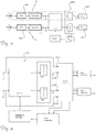
- the MIMO technique for providing short distance radio relays with an increased transmission capacity uses, for example, a radio link configuration according to the diagram shown in Figure 1 comprising two transmitting antennas AT1 and AT2 which are positioned at a distance "d" from each other and which transmit with the same polarization (co-polar transmission) a respective signal tx1,tx2 both using the same radio link, on the same carrier frequency (generally within the microwave bands) and towards two receiving antennas, AR1, AR2, situated at a distance L (possibly a few kilometers, but normally less than about 20 km) from the respective transmission antennas AT1,AT2 and at a distance from each other typically, but not necessarily, again equal to "d".
- a radio link configuration according to the diagram shown in Figure 1 comprising two transmitting antennas AT1 and AT2 which are positioned at a distance "d" from each other and which transmit with the same polarization (co-polar transmission) a respective signal tx1,tx2 both using the same radio link, on the same carrier frequency (generally within the
- the signals received by the single antennas are defined as being in total interference, namely composite signals which cannot be intrinsically discriminated during reception into the useful component and the interfering component, since they require appropriate recognition and separation techniques.
- the diagram illustrated shows the antennas spaced in the vertical direction, as often occurs when using the same post or pylon.
- the system is not limited in terms of the direction of the spacing, be it vertical, horizontal or according to needs.
- the signals transmitted tx1,tx2 are generated by a respective, conventional, modulator/transmitter functional block MT1,MT2 which has at its input a respective baseband source digital flow D1,D2.
- a first problem associated with this optimal configuration consists in the need to ensure optimum spacing between the antennas, whereby, in order to achieve this, it is required to increase the antenna supporting infrastructures to an extent which normally is not acceptable for system design engineers. From an industrial and commercial point of view it is therefore difficult to be able to satisfy the requirement for an optimal system configuration.
- the system thus defined as suboptimal is characterized by a performance which is inferior to that which can be obtained with an optimal system since it results in a loss in terms of the error threshold margin, i.e. incorrect decoding starts earlier when the channel degrades following a disturbance of the propagation. This occurs because cancellation of the interfering signal results in a smaller increase or even no increase in the actual energy of the useful signal.
- the loss of error threshold margin results in a reduction in the actual time for which the most effective modulation is maintained, this in turn resulting in a smaller increase in the possible transmission capacity.
- EP 2 922 193 discloses a method of demodulating, reconstructing and estimating the symbols of three signals transmitted in total mutual interference on a MIMO radio relay having three transmission/reception antennae, which method uses the peculiar geometry with three antennae of the radio relay to cancel the mutual interference from the three received signals. This method is of very limited applicability and no mention is made of how improve the reliability of the obtained estimates.
- US 2008/025442 A1 discloses an interference cancellation receiver using an LLR calculator considering the Euclidian distance in a constellation far all signal combinations of the interference received signals.
- the technical problem which is posed, therefore, is that of developing a method and an apparatus which are able to achieve in a particularly simple and low-cost manner an improvement in the reliability of the data transmission on short-range MIMO radio relays on which multiple, isofrequential and co-polar modulated signals are transmitted, allowing, during reception, a reliable separation of the useful components from the interfering components of the signals received by multiple receiving antennas of the said radio relays and a reliable estimate of the modulation symbols carried by the said transmitted signals.
- this method and this apparatus should allow a further increase in the transmission capacity of short distance MIMO radio relays comprising two transmitting/receiving antennas per polarization, by introducing improvements which allow an increase in the capacity and/or reliability of the transmission channel, without varying the positioning of the pre-existing antennas.
- each transmitting antenna AT1,AT2 transmits a respective signal tx1,tx2 generated by a respective conventional modulator/transmitter unit MT1,MT2 which receives at its input a respective baseband source data flow D1,D2; in the example shown it is assumed, for easier description, that the values assumed by tx1,tx2 in the appropriate symbol times are precisely synchronized with the corresponding information symbols of the source signals D1,D2 and that the transmitted signals tx1,tx2 therefore do not contain additional noise components compared to the source flows D1,D2.
- the modulator/transmitter units MT1,MT2 comprise the circuitry for implementing the operations for encoding the digital information and generating the high-frequency signal (microwaves) which is amplified by the transmitter module TX1,TX2 connected to a polarization of the antenna AT1,AT2.
- Each signal transmitted tx1;tx2 will therefore comprise a sequence of symbols of the modulation constellation used by the respective modulator/transmitter unit MT1,MT2.
- the transmitter modules TX1,TX2 are located each in an ODU (outdoor unit) located immediately behind the respective transmitting antenna AT1, AT2 in order to avoid waveguide link losses between transmitter and antenna; these ODUs comprise the local oscillators OL1, OL2 which are separate from and independent of each other.
- the signal tx1 transmitted by the first antenna AT1 propagates towards the first antenna AR1 along its primary path of length L and is received ( Fig. 1 ) by the first receiving antenna AR1;
- phase-shift between the useful signals and the interfering signals depends on the predefined geometry of the radio link, as summarized above.
- the method and the apparatus according to the invention are applicable to telecommunications systems comprising a short-distance MIMO radio link with at least two pairs of transmission/reception antennas AT1-AR1;AT2-AR2 for each transmission polarization, wherein each of said receiving antennas AR1,AR2 is designed to receive a respective high-frequency signal comprising a useful component, corresponding to the signal transmitted by the respective transmitting antenna, and an interfering component, formed by the signal transmitted by the other transmitting antenna.
- each receiving antenna Downstream of each receiving antenna there is a corresponding reception/demodulation chain MR1,MR2: a receiver/amplifier block RX1,RX2 upstream of a circuit provided with a similar synthesized local oscillator OLr1;OLr2 which adjusts the spectrum of the signal received to frequencies lower than the high transmission frequencies (microwaves).
- these components are also contained inside an outdoor unit which in the practical applications comprises both a transmitter/modulator block and a receiver/demodulator block MR1,MR2, the links being usually bidirectional. There is also a low-speed exchange of information (feedback) from the reception site to the transmission site.
- Each receiver/demodulator block MR1,MR2 introduces into the respective signal received a noise component n1,n2 including various noise factors, such as thermal noise of the receiver and a phase noise due to the jitter of the local demodulation oscillator OLr1, OLr2.
- each receiver/demodulator module MR1;MR2 ( Fig.3 ) has at its output a received signal rx1,rx2 which is the sum of:
- the received signals rx1,rx2 thus formed continue therefore downstream, in the reception processing chain towards a reconstruction/estimation assembly DMR which performs the actual demodulation ( Figs. 2 and 3 ) of the respective signal received, i.e. the reconstruction of the transmitted signal tx2;tx1 by means of cancellation of the interfering component tx2;tx1 of each received signal rx1,rx2 and a subsequent estimate (slice) tx1 ⁇ ,tx2 ⁇ of the constellation symbols transmitted.
- a reconstruction/estimation assembly DMR which performs the actual demodulation ( Figs. 2 and 3 ) of the respective signal received, i.e. the reconstruction of the transmitted signal tx2;tx1 by means of cancellation of the interfering component tx2;tx1 of each received signal rx1,rx2 and a subsequent estimate (slice) tx1 ⁇ ,tx2 ⁇ of the constellation symbols transmitted.
- DMR reconstruction/estimation assembly
- interconnection IC between the two reception branches c1,c2 which allows the exchange of the respective received signals rx1,rx2 which, suitably rotated by suitable cancellation rotation coefficients, and where necessary amplified, will be added together in a node for reconstruction of each signal transmitted, in order to perform the mutual cancellation of the interfering components present in each received signal rx1,rx2.
- the reception ODUs are preferably separate.
- This condition highlights an aspect which influences the reconstruction of the signals transmitted by means of mutual cancellation: the local oscillators OLr1,OLr2 of the receivers are realized with a synthesizer which generates a sinusoid which does not have an absolute degree of purity, namely has a certain jitter (deviation) which the reconstruction assembly DMR must attempt to make allowance for by means of suitable algorithms.
- pilot symbols have been used for this purpose: namely part of the transmission and processing capacity has been sacrificed in order to insert into the sequence of symbols transmitted a number of symbols which are known beforehand to the receiver and which provide it with a periodic reference for recovery of the phase synchronism, thus making it possible to avoid unification of the two ODUs comprising the respective reception/demodulation blocks MR1,MR2 with common connection thereof to a same local oscillator considered to be inconvenient and a source of problems.
- the independence of the local oscillator on the reception side increases the difficulty of the mutual cancellation interference: the reconstruction of each stream of constellation symbols carried by a respective transmitted signal tx1,tx2 is in fact disturbed by the sum of the two jitter values of the local oscillators OLr1,OLr2 of the two receiver/demodulator blocks MR1,MR2.
- the present invention is applicable in particular to the radio links operating with MQAM modulation with a high number of levels, i.e. modulation constellation symbols, in particular at least 256 levels.
- modulation constellation symbols i.e. modulation constellation symbols
- the sensitivity to random rotation noise (jitter noise) constitutes a significant drawback of such modulation.
- reconstruction of the signals transmitted is performed by a reconstruction block H -1 which receives at its input the demodulated received signals rx1,rx2 and comprises an adder node in which linear addition of the demodulated received signals rx1,rx2 is performed, said signals being suitably phase-shifted and/or amplified on the basis of given coefficients using the technique known in the field as "channel matrix H inversion".
- coefficients are generally updated and adapted using a known technique for adaptive updating of the inverse channel matrix H -1 coefficients, normally performed making use of the instantaneous residual error present on the linear outputs (reconstructed signals) of the reconstruction block H -1 .
- the output of the reconstruction/estimation assembly DMR is therefore a first vector [tx1 ⁇ ;tx2 ⁇ ] of estimates of the transmitted signals, formed by a respective modulation constellation symbol of the respective transmitted signal tx1,tx2, each estimate being emitted by the slicer of the respective reception and reconstruction branch c1,c2 of the link based on a respective received signal rx1,rx2.
- the error rate of these initial estimates tx1 ⁇ ;tx2 ⁇ may be very high, in this case and purely by way of example calculatable at an estimated error rate such as to give a BER ⁇ 0.05 (in terms of symbol errors affecting the estimate tx1 ⁇ ;tx2 ⁇ , and for 256 QAM modulation, this corresponding to a symbol error rate SER of more than 40%), if the cancellation/reconstruction is to be performed in a linear manner based on so-called channel H matrix inversion.
- a technical problem is therefore that of improving the estimate of the transmitted signals, in particular when this estimate is affected by significant noise and therefore a high error level.
- An object of the present invention is to provide an apparatus and a method for the revision of estimates of the symbol carried by the transmitted signals tx1,tx2 able to be implemented downstream of the reconstruction and estimation assembly DMR of the prior art, in order to improve the reconstruction and estimation of the symbols transmitted, hitherto negatively affected by the aforementioned drawbacks.
- a revision apparatus 100 is designed to be arranged between the preceding slicers of the reconstruction/estimation assembly DMR and the error correctors EC1,EC2, so as to output a pair of estimates tx1 ⁇ ; tx2' ⁇ of the symbols carried by the transmitted signals tx1,tx2, revised with respect to the preceding initial estimates with an operating speed such that the results of the revision may also be used by other units of the system.
- the method/apparatus also outputs information relating to the residual error associated with the slicing performed on the revised estimates, which may be used, if necessary, by a specially designed error corrector. In this way the overall performance features of the system are improved up to the estimates tx1 ⁇ ;tx2 ⁇ of the symbol carried by the transmitted signals and the error corrector is enabled in turn to increase its performance.
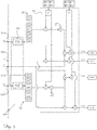
- the revision apparatus 100 comprises signal inputs 101a-b for the initial estimates tx1 ⁇ ;tx2 ⁇ of the transmitted constellation symbols tx1,tx2 emitted by the preceding slicers of the reconstruction/slicer assembly DMR following the reconstruction process by means of cancellation of an interfering component and subsequent estimate; these initial estimates tx1 ⁇ ;tx2 ⁇ are, as mentioned, generally affected by a certain significant error rate which, in the case of a lot of noise, may be very high.
- the revision apparatus 100 also has signal inputs 101c-d for the original, received and demodulated, signals emitted by the respective reception/demodulation blocks MR1,MR2 of the respective first and second reception branches c1;c2.
- a revision apparatus 100 comprises:
- the first selector module 150 therefore selects at least one pair tx1 ⁇ j;tx2 ⁇ i of possible constellation symbols, one being carried by the first transmitted signal and one being carried by the second transmitted signal tx1;tx2, respectively, each selected pair comprising:
- the symbol tx2 ⁇ j applied onto the second received signal rx2 results in the same symbol estimate tx1 ⁇ i of the first transmitted signal tx1 used for the cross-check.
- the pair tx1 ⁇ j, tx2 ⁇ i is selected as a possible revised pair of estimates of the symbols carried by the transmitted signals.
- the pair of estimates tx1 ⁇ , tx2 ⁇ provided by the first linear cancellation level results in a single pair of possible estimates tx1 ⁇ i, tx2 ⁇ j selected by the selector module 150, namely that the revision by the first selector confirms the estimate of the symbol carried by the first/second transmitted signal, performed by the reconstruction and estimation assembly DMR.
- the selector 150 selects more than one pair of possible estimates of the symbol transmitted by each signal, which verify the selection condition of the first selector module.
- the apparatus 100 comprises a second selector module 160 able to select a pair of possible estimates tx1 ⁇ j;tx2 ⁇ i of the symbol transmitted by the first and second transmitted signal tx1,tx2, out of the at least one pair(s) selected by the first selector module, which is characterized by the minimum sum of the residual quadratic errors calculated for the symbol estimates tx1 ⁇ c1i;tx1 ⁇ c2i, tx2 ⁇ c1j;tx2 ⁇ c2j processed and for the respective reconstructed signals tx1c1i;tx1c2i, tx2c1j;tx2c2j, the processed estimates corresponding to one tx1 ⁇ j or the other tx2 ⁇ i symbol estimate of the selected pair of estimates which have checked the selection condition of the selected pair being examined during the first selection step.
- a second selector module 160 able to select a pair of possible estimates tx1 ⁇ j;tx2 ⁇ i of the symbol transmitted by the first and second transmitted signal tx
- This second selection step advantageously makes use of the fact that the residual error err11, present in the reconstruction of one of the transmitted signals tx1 carried out on the first signal received, represents the instantaneous thermal noise of the receiver of the first reception branch c1 upon reception of the signal carried by the transmitted signal; in the same way, the residual error err12 present in the reconstruction of that same transmitted signal tx1 performed on the other (second) received signal rx2 represents the instantaneous thermal noise of the receiver of the other (second) reception branch c2.
- each extended set tx1 ⁇ , tx2 ⁇ of adjacent symbols constructed therefore comprises at least nine possible estimates tx1 ⁇ i ,tx2 ⁇ i of the constellation symbol carried by the respective transmitted signal tx1,tx2, including the initial estimate tx1 ⁇ ;tx2 ⁇ received at the input of the apparatus 100.
- Two vectors tx1 ⁇ , tx2 ⁇ of possible estimates of the symbol carried by the transmitted signal are thus obtained, one being associated with the first transmitted signal tx1 and one being associated with the second transmitted signal tx2.
- a suitable value outside the constellation e.g. -11+17i
- each extended set of possible estimates of the symbol carried by a respective transmitted signal tx1;tx2 will be identified as elements tx1 ⁇ i and tx2 ⁇ i of a respective vector tx1 ⁇ , tx2 ⁇ associated with a respective initial estimate tx1 ⁇ ,tx2 ⁇ , where i indicates the i-th element (in the example the i-the column) of the carrier, as illustrated in Table 3.
- Table 3 Synthetic notation for the carriers tx1 ⁇ , tx2 ⁇ of possible estimates of the symbol carried by the transmitted signal tx1,tx2 tx1 ⁇ 1 tx1 ⁇ 2 tx1 ⁇ 3 tx1 ⁇ 4 tx1 ⁇ 5 tx1 ⁇ 6 tx1 ⁇ 7 tx1 ⁇ 8 tx1 ⁇ 9 tx2 ⁇ 1 tx2 ⁇ 2 tx2 ⁇ 3 tx2 ⁇ 4 tx2 ⁇ 5 tx2 ⁇ 6 tx2 ⁇ 7 tx2 ⁇ 8 tx2 ⁇ 9 2) For each reception branch c1,c2 associated with a respective received signal rx1,rx2 a calculation is carried out for the elements of the respective vectors tx1c1 , tx2c1 ; tx1c2 , tx2c2 of reconstruction signals of the first and second transmitted signal, each reconstructed by means of non-linear cancellation of a respective interfering component, performed by subtracting from the respective
- Table 4 Synthetic notation for vectors tx1c1 , tx2c1 of signals reconstructed from the signal rx1 received on the first reception branch c1 tx1c1 1 tx1c1 2 tx1c1 3 tx1c1 4 tx1c1 5 tx1c1 6 tx1c1 7 tx1c1 8 tx1c1 9 tx2c1 1 tx2c1 2 tx2c1 3 tx2c1 4 tx2c1 5 tx2c1 6 tx2c1 7 tx2c1 8 tx2c1 9
- Table 5 Synthetic notation for vectors tx1c2 , tx2c2 of signals reconstructed from the signal rx2 received on the second reception branch c2 tx1c2 1 tx1c2 2 tx
- the method selects, if present, at least one pair of revised estimates tx1 ⁇ j;tx2 ⁇ i which pass the combined check whereby a possible estimate tx2 ⁇ i, used as canceller on both received signals rx1 and rx2 for non-linear cancellation of the interfering signal, leads to the other estimate tx1 ⁇ j of the pair of revised estimates.
- This condition selects at least one existing pair of estimates of the transmitted signals, which are probably correct, and excludes other estimates which are probably incorrect, with a good degree of efficiency.
- met1 is always equal to met2 and it is therefore possible to calculate equally well the sum of the slicer quadratic errors based on one estimate tx2 ⁇ i or the other estimate tx1 ⁇ j of the pair selected.
- the method has nevertheless performed a revision of the initial estimates, not having found possible estimates which are better according to the selection criteria.
- the method according to the invention is very advantageous in terms of computational cost; it is in fact rare to have to search in more than three k-th columns for the pair with minimum sum of residual quadratic errors, associated with either estimate, in order to select the pair of revised estimates of the symbol carried by the transmitted signals. It is therefore clear how the method according to the invention is quick and has a low processing cost.
- the method is able to provide an exact revision of about 88% of the initial incorrect estimates tx1 ⁇ , tx2 ⁇ which occur in the presence of generic noise sources such as to produce a BER of 5*e-2 for 256-QAM modulation.
- At least one pair of possible constellation symbols is selected, one symbol being carried by the first transmitted signal and the other symbol being carried by the second transmitted signal tx1;tx2, respectively, which appear in all the lists L11, L12, L21 and L22 previously formed.
- the first selector module therefore selects at least one pair tx1 ⁇ j;tx2 ⁇ i of possible constellation symbols, one symbol being carried by the first transmitted signal and the other symbol being carried by the second transmitted signal tx1;tx2, respectively, each selected pair comprising:
- the slicer residual errors associated with each estimate of the transmitted symbol sliced on the basis of a respective reconstructed signal and useful for the second selection step may be calculated based on said reconstructed signal and respective estimate following said first selection step and only for those processed estimates which satisfy the selection condition and which will be examined during the second selection step. In this way the computational time necessary for calculating the slicer residual errors for estimates which will not be used or selected is avoided.
- the rotation coefficients for cancellation of the first series of coefficients are in total four in number: ⁇ 11, ⁇ 12, ⁇ 21, ⁇ 22.
- the coefficients for cancellation are preferably updated by means of a method which comprises the calculation of a correlation such that, for example, the first coefficient ⁇ 11 t used for a symbol (tx2 ⁇ i) received at a symbol instant t+1 is updated, for use at the following symbol time t+2, subtracting from the said coefficient ⁇ 11 t the product of the slicer residual error - associated with a reconstructed signal txlcli and respective estimate tx1 ⁇ c1i processed using the said coefficient ⁇ 11 t - multiplied by the symbol estimate tx2 ⁇ i used for cancellation, both relating to the instant t+1, wherein said estimate tx1 ⁇ c1i is an estimate corresponding to the symbol estimate tx1 ⁇ j of the transmitted signal tx1 of the pair selected as pair of revised estimates, and wherein said residual error err11i is multiplied by the other symbol estimate tx2 ⁇ i of the selected pair.
- a preferred method known in the branch is the so-called gradient method used, for example, in decision feedback equalizers (DFE).
- DFE decision feedback equalizers
- the values of the cancellation rotation coefficients calculated in the reconstruction/estimation assembly DMR based on the inverse channel matrix H -1 perform tracking of the instantaneous phase difference between the local oscillators of the reception receivers associated with the first and second receiving antennas respectively.
- this difference consists of a jitter noise with double the power compared to the configuration with a single antenna/receiver (SISO). This is one of the possible further degradation factors introduced by the MIMO system architecture adopted.
- the method and the apparatus of the invention are therefore able to provide two improvements for counteracting this degradation factor, allowing the choice of architecture which offers system advantages of interest to be maintained (separate reception ODUs and therefore LOs).
- a first improvement consists in the possibility of the DMR assembly being able to base the realization of the inverse channel matrix H -1 on estimates of the transmitted symbol which are affected by a very much lower slicing error rate; this is possible owing to the revision method of the invention which allows the estimates emitted by the DMR assembly to be revised in a suitably rapid manner.
- the method according to the invention may therefore advantageously also make available to the first reconstruction level DMR the estimates revised by the method so that the consequent slicing residual errors are more reliable.
- a second improvement consists in the fact that the signals reconstructed by means of cancellation according to the invention are reconstructed on the basis of a single signal received which has only a reception jitter noise. Consequently, following the first improvement where, owing to an improved reconstructed cancellation carrier, the present method may be provided at the input with input estimates tx1 ⁇ , tx2 ⁇ which are certainly more reliable, but still dependent on the tracking of a significant amount of jitter noise - still doubled as characteristic of the linear MIMO system - a second improvement of the present method will consist in the updating of the phase rotation coefficients for cancellation.
- phase rotation coefficients ⁇ 11r, ⁇ 12r, ⁇ 21r, ⁇ 22r of the second series of coefficients are also four in number and are updated by means of a method which comprises the calculation of a correlation such that the coefficient ⁇ r t used for a symbol received at an instant t+1 is updated, for use at the next symbol time t+2, by subtracting from the said coefficient the product of the slicer residual error multiplied by the reconstructed signal, both associated with the respective sliced symbol estimate to which a revised symbol estimate of the pair selected for emission corresponds.
- a preferred method known in the sector is that used for decision-directed carrier recovery.
- the invention is not limited in this respect and it is always possible to implement the revision method considering also further symbols which are not immediately adjacent, by simply expanding the vectors/extended sets of possible estimates of the transmitted signal so that they incorporate also these further elements (therefore creating an extended set of possible estimates of the transmitted symbol, for example the vector tx1 ⁇ , comprising more than nine elements).
- the following steps in the method remain unchanged with respect to the preferred example described.
- the method is likewise applicable also to possible other constellations, also not of the QAM type, in which there are a plurality of adjacent symbols.
- pilot symbols for other purposes namely pilot symbols which are known beforehand to the receiver and which do not carry significant information data, but are used by the receiver for example for carrier realignment, rephasing or recovery operations
- the method may advantageously benefit from their presence in order to obtain a simplification of the first selection step and better certainty of the revision performed. This is particularly relevant if the pilot symbols are in free positions in the two transmission channels, namely they occur in symbol instants which do not coincide.
- the second symbol tx2 transports a symbol tx2 ⁇ 1 which is known to the receiver as being a pilot symbol
- the initial estimate tx2 ⁇ 1 of the symbol carried by the second transmitted signal tx2 is a safe slice.
- the first selection step will comprise the selection of one pair (and/or of sole pairs) which comprise(s) the symbol estimate tx2 ⁇ i corresponding to the pilot symbol and the exclusion of pairs which do not comprise an estimate of the symbol carried by the transmitted signal which corresponds to the pilot symbol.
- the method is applicable also to a telecommunications system which implements a further increase in the capacity of the channel by transmitting in parallel with each signal tx1,tx2 transmitted with a given polarization an isofrequential signal having orthogonal polarization, the two signals being intrinsically able to be discriminated so that they may be separated during reception using common XPD techniques for eliminating the cross-polar interference.
Landscapes
- Engineering & Computer Science (AREA)
- Computer Networks & Wireless Communication (AREA)
- Signal Processing (AREA)
- Radio Transmission System (AREA)
Claims (13)
- Verfahren zur Überprüfung von- einer ersten Initialen Schätzung (tx1^) eines Symbols, das von einem ersten Signal (txl) getragen wird, das von einer ersten Sendeantenne (AT1) einer MIMO, LOS (Line-Of-Sight) Richtfunkverbindung übertragen wird und- einer zweiten Initialen Schätzung (tx2^) eines Symbols, das von einem zweiten Signal (tx2) getragen wird, das von einer zweiten Sendeantenne (AT2) einer MIMO LOS-Richtfunkverbindung übertragen wird,wobei die beiden Signale (tx1,tx2) in völliger gegenseitiger Interferenz auf der MIMO LOS-Funkverbindung übertragen werden,
wobei die erste initiale Schätzung (tx1^) von einem Slicer eines jeweiligen ersten Verbindungszweiges (c1) zum Empfangen und Rekonstruieren nach einem Verfahren zur Demodulation und Rekonstruktion des ersten Sendesignals (txl) durch gegenseitiges Löschen eines ersten Signals (rx1), das auf einer ersten Antenne (AR1) der Funkverbindung stromaufwärts des ersten Empfangszweiges (c1) empfangen wird, und eines zweiten Signals (rx2), das von einer zweiten Empfangsantenne (AR2) der Verbindung empfangen wird, ausgegeben wird, wobei die empfangenen Signale (rx1, rx2) jeweils das erste Signal (tx1) und das zweite Signal (tx2) umfassen, die in totaler gegenseitiger Interferenz übertragen werden,
wobei die zweite initiale Schätzung (tx2^) von einem Slicer eines jeweiligen zweiten Zweiges (c2) zum Empfangen und Rekonstruieren stromabwärts der zweiten Empfangsantenne (AR2) der Funkverbindung nach einem Verfahren zur Demodulation und Rekonstruktion des zweiten gesendeten Signals (tx2) durch gegenseitige Löschung des von der zweiten Antenne (AR2) empfangenen zweiten Signals (rx2) und des ersten Empfangssignals (rx1) ausgegeben wird,
dadurch gekennzeichnet, dass es die folgenden Schritte umfasst:- für jede initiale Schätzung (tx1^; tx2^) des übertragenen Symbols: Bildung einer erweiterten Menge (tx1^; tx2^) möglicher Symbole, die vom jeweiligen Sendesignal (tx1^; tx2^) getragen werden, umfassend mindestens die Modulationskonstellationssymbole direkt angrenzend an die jeweilige initiale Schätzung (tx1^; tx2^) und die initiale Schätzung (tx1^; tx2^) selbst;- Bildung eines ersten Satzes von Rekonstruktionssignalen (tx1c1i) des ersten gesendeten Signals (tx1), die jeweils durch Subtraktion eines entsprechenden i-ten Elements des erweiterten Satzes möglicher Symbole, die vom zweiten gesendeten Signal (tx2) getragen werden, von dem ersten empfangenen Signal (rx1) erhalten werden;- Bildung eines zweiten Satzes von Rekonstruktionssignalen (tx1c2i) des ersten Sendesignals (tx1), die jeweils durch Subtraktion eines entsprechenden i-ten Elements des erweiterten Satzes möglicher Symbole, die vom zweiten Sendesignal (tx2) getragen werden, von dem zweiten empfangenen Signal (rx2) erhalten werden;- Bildung eines ersten Satzes von Rekonstruktionssignalen (tx2c1i) des zweiten Sendesignals (tx2), die jeweils durch Subtraktion eines entsprechenden i-ten Elements des erweiterten Satzes möglicher Symbole, die vom ersten Sendesignal (txl) getragen werden, von dem ersten empfangenen Signal (rx1) erhalten werden;- Bildung eines zweiten Satzes von Rekonstruktionssignalen (tx2c2i) des zweiten Sendesignals (tx2), die jeweils durch Subtraktion eines entsprechenden i-ten Elements des erweiterten Satzes möglicher Symbole, die vom ersten Sendesignal (tx1) getragen werden, von dem zweiten empfangenen Signal (rx2) erhalten werden;- Schätzung (tx1^c1i; tx2^c1i; tx1^c2i; tx2^c2i) des jedem rekonstruierten Signal zugeordneten Konstellationssymbols durch Entscheidung auf der Grundlage des jeweiligen rekonstruierten Signals (tx1c1i; tx2c1i; tx1c2i; tx2c2i);- Auswählen eines Paares (tx1^j;tx2^i) möglicher Konstellationssymbole, wobei jeweils eines vom ersten Sendesignal und eines vom zweiten Sendesignal (tx1;tx2) getragen wird, wobei das ausgewählte Paar (tx1^j; tx2^i) umfasst:• ein j-tes Symbol (tx1^j) des erweiterten Satzes (tx1^) möglicher Schätzungen des Symbols, das vom ersten übertragenen Signal (tx1) getragen wird, was entspricht:▪ sowohl auf das Symbol (tx1^c1i), das auf der Grundlage des Rekonstruktionssignals (tx1c1i) des ersten Sendesignals geschnitten wurde, rekonstruiert, indem vom ersten empfangenen Signal (rx1) ein i-tes Symbol (tx2^i) des Satzes (tx2^) möglicher Symbole, die vom zweiten Sendesignal getragen werden, subtrahiert wird,▪ und auf das Symbol (tx1^c2i), das auf der Grundlage des Rekonstruktionssignals (tx1c2i) des ersten Sendesignals (tx1) geschnitten wurde, rekonstruiert durch Subtraktion des gleichen i-ten Symbols (tx2^i) des Satzes (tx2^) möglicher Symbole, die vom zweiten Sendesignal getragen werden von dem zweiten empfangenen Signal (rx2); und• ein i-tes Symbol (tx2^i) des erweiterten Satzes (tx2^) möglicher Schätzungen des Symbols, das vom zweiten Sendesignal (tx2) getragen wird, das entspricht:▪ sowohl auf das Symbol (tx2^c1j), das auf der Grundlage des Rekonstruktionssignals (tx2c1j) des zweiten Sendesignals geschnitten wurde, rekonstruiert durch Subtraktion des j-ten Symbols (tx1^j) der Menge (tx1^) möglicher Symbole, die vom ersten Sendesignal (txl) getragen werden, vom ersten empfangenen Signal (rx1),▪ und auf das Symbol (tx2^c2j), das auf der Grundlage des Rekonstruktionssignals (tx2c2j) des zweiten Sendesignals (tx2) geschnitten wurde, rekonstruiert durch Subtraktion des gleichen j-ten Symbols (tx1^j) des vom ersten Sendesignal (tx1) getragenen Satzes möglicher Symbole vom zweiten empfangenen Signal (rx2);- Emission eines Paares (tx1^j;tx2^i) von Schätzungen, die als revidierte Schätzungen (tx1^;tx2^') des Symbols ausgewählt wurden, das jeweils von dem ersten und zweiten übertragenen Signal (tx1;tx2) getragen wird. - Verfahren nach Anspruch 1, wobei jeder Schritt zur Bildung eines Satzes von Rekonstruktionssignalen eines der übertragenen Signale die Drehung der Symbolschätzung umfasst, die von dem jeweils empfangenen Signal (rx1;rx2) um einen entsprechenden ersten Koeffizienten (ϕ11, ϕ12, ϕ21,ϕ22) der Drehung für die Löschung abzuziehen ist, und die Drehung des Ergebnisses der Abziehungum einen entsprechenden zweiten Koeffizienten (ϕ11r, ϕ12r, ϕ21r,ϕ22r) der Drehung.
- Verfahren nach einem der vorhergehenden Ansprüche, wobei, wenn eines der beiden übertragenen Signale (tx1; tx2) Pilotsymbole in seiner Folge von getragenen Symbolen umfasst, das zur Emission ausgewählte Paar (tx1^j; tx2^i) zum Symbolzeitpunkt eines empfangenen Pilotsymbols das Pilotsymbol als eine überarbeitete Schätzung (tx1^'; tx2^') des vom jeweiligen übertragenen Signal getragenen Symbols umfasst.
- Verfahren nach einem der vorhergehenden Ansprüche, wobei das Paar von Schätzungen (tx1^j; tx2^i), die für die Emission ausgewählt wurden, derjenige mit dem Mindestwert der Summe (met1; met2) der quadratische Slicer-Restfehler ist, die mit:- die Schätzungen (tx1^c1i ,tx1^c2i) des vom ersten Sendesignal (tx1) getragenen Symbols, die auf der Grundlage der jeweiligen rekonstruierten Signale (tx1c1i ,tx1c2i) geschnitten sind, denen die Schätzung (tx1^j) des vom ersten Sendesignal (tx1) des ausgewählten Paares getragenen Symbols entspricht, oder- die Schätzungen (tx2^c1j; tx2^c2j) des Symbols, das vom zweiten Sendesignal (tx2) getragen wird, die auf der Grundlage der jeweils rekonstruierten Signale (tx2clj; tx2c2j), dem die Schätzung (tx2^i) des vom zweiten Sendesignal (tx2) des ausgewählten Paares getragenen Symbols entspricht,wobei der Auswahlschritt die Berechnung des Restfehlers für jede durchgeführte Schätzung entsprechend einer Symbolschätzung eines ausgewählten Paares und die Berechnung der Summe der quadratischen Restfehler für jedes ausgewählte Paar umfasst.
- Verfahren nach dem vorhergehenden Anspruch, wobei der Wert der Summe der berechneten quadratischen Fehler zusammen mit dem Paar ausgewählter revidierter Schätzungen ausgegeben wird, um einem nachgeschalteten Fehlerkorrektor nützliche Informationen für die Korrektur von Fehlern bereitzustellen.
- Verfahren nach einem der vorhergehenden Ansprüche, wobei ein Rotationskoeffizient zum Löschen der ersten Reihe von Koeffizienten, der für einen Satz (tx1c1) von rekonstruierten Signalen verwendet wird, die sich auf eine bestimmte Symbolzeit t+1 beziehen, zur Verwendung zum nächsten Symbolzeitpunkt (t+2) aktualisiert wird, indem das Produkt des Slicer-Restfehlers (err11i), der einem rekonstruierten Signal (tx1c1i) zugeordnet ist, das unter Verwendung des Koeffizienten (φ11tt) verarbeitet wurde, und der jeweiligen Schätzung (tx1^c1i) des Symbols, das vom jeweiligen Sendesignal (tx2) getragen wird, von dem Koeffizienten (ϕ11t) subtrahiert wird, beide bezogen auf die angegebene Symbolzeit (t+1);wobei die Schätzung (tx1^c1i) eine Schätzung ist, die der Symbolschätzung (tx1^j) des übertragenen Signals (tx1) des Paares entspricht, das als Paar von überarbeiteten Schätzungen ausgewählt ist, und wobei der Restfehler mit der anderen Symbolschätzung (tx2^i) des ausgewählten Paares multipliziert wird.
- Verfahren nach dem vorhergehenden Anspruch, dadurch gekennzeichnet, dass die Phasendrehzahlkoeffizienten für die Löschung zusammen mit dem ausgewählten Paar überarbeiteter Schätzungen ausgegeben werden, um einen Rekonstruktions- und Schätzblock (DMR) der Funkverbindung mit aktualisierten Phasendrehzahlkoeffizienten für die Löschung bereitzustellen, der in der Lage ist, die Zuverlässigkeit der aufeinanderfolgenden initalen Schätzungen, die von dem Block (DMR) gesendet werden, zu verbessern.
- Verfahren nach einem der vorstehenden Ansprüche, wobei die Phasendrehzahlkoeffizienten (ϕ11r, ϕ12r, ϕ21r, ϕ22r) der zweiten Reihe von Koeffizienten mittels eines Verfahrens aktualisiert werden, das die Berechnung einer Korrelation umfasst, so dass ein für eine bestimmte Symbolzeit t+1 verwendeter Koeffizient ϕrt) zur Verwendung zum nächsten Symbolzeitpunkt (t+2) aktualisiert wird, Subtrahieren des Produkts des Slicer-Restfehlers (err11i) von dem Koeffizienten, der einem rekonstruierten Signal (tx1c1i) zugeordnet ist, das unter Verwendung des Koeffizienten (φ11t) und mit der jeweiligen Schätzung (tx1^c1i) des Symbols, das vom jeweiligen Sendesignal (tx2) getragen wird, verarbeitet wird, beide bezogen auf die gegebene Symbolzeit (t+1);wobei die Schätzung (tx1^c1i) eine Schätzung ist, die der Symbolschätzung (tx1^j) des übertragenen Signals (tx1) des Paares entspricht, das als Paar von überarbeiteten Schätzungen ausgewählt ist,
und wobei der Slicerfehler (err11i) mit dem rekonstruierten Signal (tx1c1i) multipliziert wird. - Revisionsvorrichtung (100) zum Überprüfen:- einer ersten intialen erste Schätzung (tx1^) eines Symbols, das von einem ersten Signal (tx1) getragen wird, das von einer ersten Sendeantenne (AT1) eines MIMO, Line-Of-Sight, optischer Reichweite, Richtfunkverbindung, und- einer zweiten intialen Schätzung (tx2^) eines Symbols, das von einem zweiten Signal (tx2) getragen wird, das von einer zweiten Sendeantenne (AT2) der MIMO LOS-Funkverbindung übertragen wird,wobei die beiden Signale (tx1,tx2) in völliger gegenseitiger Beeinflussung auf der MIMO LOS-Funkverbindung übertragen werden,
wobei die erste anfängliche Schätzung (tx1^) durch einen Entscheider eines jeweiligen ersten Zweiges (c1) zum Empfangen und Rekonstruieren der Verbindung ausgegeben wird, nach einem Verfahren zur Demodulation und Rekonstruktion des ersten Sendesignals (tx1) durch gegenseitige Löschung eines ersten Signals (rx1), das auf einer ersten Empfangsantenne (AR1) der Funkverbindung stromaufwärts des ersten Empfangszweiges (c1) empfangen wird, und eines zweiten Signals (rx2), das von einer zweiten Empfangsantenne (AR2) der Funkverbindung empfangen wird, wobei die empfangenen Signale (rx1, rx2) jeweils das erste Signal (tx1) und das zweite Signal (tx2) umfassen, die in totaler gegenseitiger Interferenz übertragen werden,
wobei die zweite intiale Schätzung (tx2^) von einem Entscheider eines jeweiligen zweiten Zweiges (c2) zum Empfangen und Rekonstruieren stromabwärts der zweiten Empfangsantenne (AR2) der Funkverbindung nach einem Verfahren zur Demodulation und Rekonstruktion des zweiten Sendesignals (tx2) mittels gegenseitiger Löschung des von der zweiten Antenne (AR2) empfangenen zweiten Signals (rx2) und des ersten empfangenen Signals (rx1) abgegeben wird, dadurch gekennzeichnet, dass sie umfasst:- ein Modul (110) zum Aufbau eines erweiterten Satzes (tx1^; tx2^) möglicher Schätzungen des durch das Sendesignal (tx1;tx2) getragenen Symbols für jede Symbolschätzung (tx1^,tx2^) des am Eingang empfangenen Sendesignals (tx1;tx2^); wobei jeder erweiterte Satz (tx1^; tx2^) das am Eingang empfangene geschätzte Symbol (tx1^; tx2^) und mindestens die acht daran angrenzenden Symbole in der Modulationskonstellation umfasst;- einen Speicher, der Register zum Speichern der verschiedenen verarbeiteten und/oder für die Verarbeitungsvorgänge erforderlichen Elemente umfasst;- einen Auslöschungsknoten (120) zum Empfangen an seinem Eingang:▪ jedes empfangene und demodulierte Signal (rx1,rx2), das von einer zugehörigen Antenne (AR1,AR2) und einem zugehörigen Empfangs-/Demodulationsblock eines jeweiligen Empfangs- und Rekonstruktionszweigs (c1,c2) stammt;▪ jeder Satz (tx1^ ; tx2^) möglicher Schätzungen des von einem der übertragenen Signale (txl;tx2) getragenen Symbols, der eine jeweilige Anfangsschätzung (tx1^;tx2^) des übertragenen Symbols und der jeweiligen benachbarten Symbole in der Modulationskonstellation enthält;und zum Bereitstellen an seinem Ausgang für jedes empfangene Signal (rx1;rx2):einen jeweiligen ersten Satz (tx1c1 ; tx1c2) von Rekonstruktionssignalen des ersten gesendeten Signals (tx1), die jeweils mittels nichtlinearer Löschung rekonstruiert werden, die durch Löschung einer störenden Komponente (tx2) aus dem jeweiligen empfangenen Signal (rx1,rx2) mittels eines entsprechenden Symbols des Satzes (tx2^) möglicher Schätzungen des vom zweiten gesendeten Signal (tx2) getragenen Symbols erfolgt;und einen jeweiligen zweiten Satz (tx2c1; tx2c2) von Rekonstruktionssignalen des zweiten gesendeten Signals (tx2), die jeweils mittels nichtlinearer Löschung rekonstruiert werden, die durch Löschung einer störenden Komponente (tx1) aus dem jeweiligen empfangenen Signal (rx1, rx2) mittels eines entsprechenden Symbols des Satzes (tx1^) von möglichen Schätzungen des vom ersten gesendeten Signal (tx1) getragenen Symbols durchgeführt wird;- ein Slicermodul, um eine Schätzung (tx1^c1i; tx2^c1i; tx1^c2i; tx2^c2i) des jedem rekonstruierten Signal zugeordneten Konstellationssymbols durch Entscheidung auf der Grundlage des jeweiligen rekonstruierten Signals (tx1c1i ; tx2c1i ; tx1c2i ; tx2c2i) bereitzustellen;- ein Auswahlmodul zum Auswählen eines Paares (tx1^j;tx2^i) möglicher Konstellationssymbole, wobei jeweils eines vom ersten Sendesignal (tx1) und eines vom zweiten Sendesignal (tx2) getragen wird, wobei das ausgewählte Paar umfasst:o ein j-tes Symbol (tx1^j) des erweiterten Satzes (tx1^) von möglichen Schätzungen des Symbols, das vom ersten übertragenen Signal (tx1) getragen wird, was entspricht:▪ sowohl zum geschnittenen Symbol, das auf der Grundlage des Rekonstruktionssignals (tx1^c1i) des ersten Sendesignals geschnitten wurde, rekonstruiert, indem vom ersten empfangenen Signal (rx1) ein i-tes Symbol (tx2^i) der Menge (tx2^) möglicher Schätzungen des Symbols, das vom zweiten Sendesignal (tx2) getragen wird, subtrahiert wird,▪ und auf das geschnittene Symbol, das auf der Grundlage des Rekonstruktionssignals (tx1c2i) des ersten Sendesignals (tx1) geschnitten wurde, rekonstruiert durch Subtraktion des gleichen i-ten Symbols (tx2^i) des Satzes (tx2^) von dem zweiten empfangenen Signal (rx2) von möglichen Schätzungen des vom zweiten Sendesignal (tx2) getragenen Symbols; undo ein i-tes Symbol (tx2^i) des erweiterten Satzes (tx2^) möglicher Schätzungen des Symbols, das vom zweiten Sendesignal (tx2) getragen wird, das entspricht:▪ sowohl auf das Symbol (tx2^c1j), das auf der Grundlage des Rekonstruktionssignals (tx2^c1j) des zweiten Sendesignals geschnitten wurde, rekonstruiert, indem vom ersten empfangenen Signal (rx1) das gleiche j-te Symbol (tx1^j) des Satzes (tx1^) der möglichen Schätzungen des Symbols, das vom ersten Sendesignal (tx1) getragen wird, subtrahiert wird,▪ und auf das Symbol (tx2^c2j), das auf der Grundlage des Rekonstruktionssignals (tx2c2j) des zweiten Sendesignals (tx2) geschnitten wurde, rekonstruiert durch Subtraktion des gleichen j-ten Symbols (tx1^j) des vom ersten Sendesignal (tx1) getragenen Satzes möglicher Symbole vom zweiten empfangenen Signal (rx2);- Ausgänge zum Senden eines ausgewählten Paares (tx1^j;tx2^i) von Schätzungen als revidierte Schätzungen (tx1^;tx2^') des Symbols, das jeweils vom ersten Sendesignal (tx1) und zweiten Sendesignal (tx2) getragen wird. - Vorrichtung nach dem vorstehenden Anspruch, dadurch gekennzeichnet, dass der Speicher Register umfasst, in denen eine erste Reihe von Rotationskoeffizienten (ϕ11, ϕ12, ϕ21, ϕ22) zum Löschen und eine zweite Reihe von Rotationskoeffizienten (ϕ11r, ϕ12r, ϕ21r, ϕ22r) gespeichert sind; und dass der Auslöschungsknoten zum Bilden von Rekonstruktionssignalen eines der übertragenen Signale jeweils einen ersten Rotator zum Drehen der vom jeweiligen Empfangssignal (rx1;rx2) abzuziehenden Symbolschätzung um einen jeweiligen ersten Rotationskoeffizienten (ϕ11, ϕ12, ϕ21, ϕ22) für die Löschung und einen jeweiligen zweiten Rotator zum Drehen des Ergebnisses der Subtraktion um einen jeweiligen zweiten Rotationskoeffizienten ϕ11r, ϕ12r, ϕ21r, ϕ22r) umfasst.
- Vorrichtung nach einem der Ansprüche 9 und 10, dadurch gekennzeichnet, dass sie zur Verwendung in Funkrelais geeignet ist, in denen eines der beiden übertragenen Signale (tx1; tx2) Pilotsymbole in ihrer Folge von getragenen Symbolen umfasst, und dass das Auswahlmodul zu einem Symbolzeitpunkt, zu dem eines der Pilotsymbole vorhanden ist, geeignet ist, ein Paar von Symbolschätzungen für die Emission auszuwählen, die das Pilotsymbol als überarbeitete Schätzung des vom jeweiligen übertragenen Signal getragenen Symbols umfassen.
- Vorrichtung nach einem der Ansprüche 9 bis 11, umfassend ein Modul zum Berechnen der Summe der quadratischen Fehler des Slicers für jedes ausgewählte Paar von Schätzungen (tx1^j; tx2^i) in Bezug auf:- die Schätzungen (tx1^c1i ,tx1^c2i) des vom ersten Sendesignal (tx1) getragenen Symbols, die auf der Grundlage von jeweils rekonstruierten Signalen (tx1c1i ,txlc2i) bestimmt wurden, denen die Schätzung (tx1^j) des vom ersten Sendesignal (tx1) des ausgewählten Paares getragenen Symbols entspricht, oder- die Schätzungen (tx2^c1j; tx2^c2j) des Symbols, das vom zweiten Sendesignal (tx2) getragen wird, auf der Grundlage der jeweils rekonstruierten Signale (tx2clj; tx2c2j), dem die Schätzung (tx2^i) des Symbols entspricht, das vom zweiten Sendesignal (tx2) des ausgewählten Paares getragen wird,und dadurch, dass die Auswahlmodule für die Emission das Paar von Schätzungen auswählen, das mit dem Minimalwert der Summe (met1 oder met2) der restlichen quadratischen Fehler am Entscheider ausgewählt wurde.
- Vorrichtung nach dem vorhergehenden Anspruch, umfassend Ausgaben für die Emission des Wertes der Summe der berechneten quadratischen Fehler zusammen mit dem Paar der ausgewählten überarbeiteten Schätzungen, um nützliche Informationen für die Fehlerkorrektur an einen Fehlerkorrektor stromabwärts der Vorrichtung bereitzustellen.
Applications Claiming Priority (1)
| Application Number | Priority Date | Filing Date | Title |
|---|---|---|---|
| ITUA2016A003410A ITUA20163410A1 (it) | 2016-05-13 | 2016-05-13 | Metodo e apparecchiatura per la revisione di stime di simboli portati da segnali trasmessi in modulazione su un ponte radio mimo |
Publications (2)
| Publication Number | Publication Date |
|---|---|
| EP3244548A1 EP3244548A1 (de) | 2017-11-15 |
| EP3244548B1 true EP3244548B1 (de) | 2018-12-12 |
Family
ID=56940166
Family Applications (1)
| Application Number | Title | Priority Date | Filing Date |
|---|---|---|---|
| EP17170120.4A Not-in-force EP3244548B1 (de) | 2016-05-13 | 2017-05-09 | Verfahren und vorrichtung zur schätzungskorrektur von symbolen, die durch modulierte signale auf einer mimo funkstrecke übertragen werden |
Country Status (2)
| Country | Link |
|---|---|
| EP (1) | EP3244548B1 (de) |
| IT (1) | ITUA20163410A1 (de) |
Cited By (1)
| Publication number | Priority date | Publication date | Assignee | Title |
|---|---|---|---|---|
| US20250030449A1 (en) * | 2021-11-11 | 2025-01-23 | Telefonaktiebolaget Lm Ericsson (Publ) | A successive interference cancellation receiver for line-of-sight multiple-input multiple-output receivers |
Family Cites Families (2)
| Publication number | Priority date | Publication date | Assignee | Title |
|---|---|---|---|---|
| KR100922938B1 (ko) * | 2006-03-09 | 2009-10-22 | 삼성전자주식회사 | 통신 시스템에서 데이터 수신 방법 및 장치 |
| ITMI20131108A1 (it) * | 2013-07-02 | 2015-01-03 | Siae Microelettronica Spa | Metodo, apparecchiatura e sistema di ricostruzione di terne di segnali trasmessi su ponti radio mimo a tre antenne per polarizzazione di trasmissione |
-
2016
- 2016-05-13 IT ITUA2016A003410A patent/ITUA20163410A1/it unknown
-
2017
- 2017-05-09 EP EP17170120.4A patent/EP3244548B1/de not_active Not-in-force
Non-Patent Citations (1)
| Title |
|---|
| None * |
Cited By (1)
| Publication number | Priority date | Publication date | Assignee | Title |
|---|---|---|---|---|
| US20250030449A1 (en) * | 2021-11-11 | 2025-01-23 | Telefonaktiebolaget Lm Ericsson (Publ) | A successive interference cancellation receiver for line-of-sight multiple-input multiple-output receivers |
Also Published As
| Publication number | Publication date |
|---|---|
| ITUA20163410A1 (it) | 2017-11-13 |
| EP3244548A1 (de) | 2017-11-15 |
Similar Documents
| Publication | Publication Date | Title |
|---|---|---|
| US8711989B1 (en) | Method and apparatus for receiving signals in a MIMO system with multiple channel encoders | |
| US9225451B2 (en) | Transmission apparatus, reception apparatus, transmission method, reception method, and method for generating multi-dimensional constellations | |
| TWI504185B (zh) | 適用於幾何閉環視線(los)多輸入多輸出(mimo)之通訊裝置及操作通訊設備之方法 | |
| US8218671B2 (en) | Receiving apparatus, receiving method and communication system | |
| US10009133B2 (en) | MIMO demodulating apparatus and method, and line-of-sight wireless communications system | |
| US20040259556A1 (en) | Wireless network with intensive frequency reuse | |
| US10523283B2 (en) | LOS-MIMO demodulation apparatus, communication apparatus, LOS-MIMO transmission system, LOS-MIMO demodulation method and program | |
| US8320505B2 (en) | Apparatus and method for receiver in multiple antenna system | |
| WO1993019526A1 (en) | Method and apparatus for estimating signal weighting parameters in a diversity receiver | |
| RU2439826C2 (ru) | Система радиопередачи и способ компенсации взаимных помех | |
| US8457096B2 (en) | Beam steering in a mesh network with repetitions | |
| CN102783107A (zh) | 一种频偏校正方法及装置 | |
| EP3244548B1 (de) | Verfahren und vorrichtung zur schätzungskorrektur von symbolen, die durch modulierte signale auf einer mimo funkstrecke übertragen werden | |
| Ju et al. | Geographic Segmented Localcasting Co-Channel Interference Mitigation Using Iterative Joint Detection and Decoding | |
| EP2555479A1 (de) | Vorrichtung und Verfahren zur Einschätzung eines Kanalkoeffizienten eines Datenunterkanals eines Funkkanals | |
| US20140086350A1 (en) | Joint Carrier Recovery for MIMO Systems | |
| JP5340196B2 (ja) | 送信ウェイト決定方法 | |
| US6650289B2 (en) | Point to point communication system with parallel links | |
| Webber et al. | Experimental evaluation of a poly-polarization multiplexing system with timing/frequency recovery for satellite communications | |
| Kim et al. | An iterative decoding technique for cooperative STBC-OFDM systems with multiple carrier frequency offsets | |
| Abdulwahab et al. | Internal pilot insertion for polar codes | |
| US11949473B2 (en) | Wireless receiving apparatus, wireless communication system, and wireless receiving method | |
| JP6223374B2 (ja) | 受信装置 | |
| Chae et al. | Reconfigurable Intelligent Surface Aided Integer Forcing MIMO | |
| CN108900239B (zh) | 一种低复杂度空间飞行器全向组网统一收发系统及方法 |
Legal Events
| Date | Code | Title | Description |
|---|---|---|---|
| PUAI | Public reference made under article 153(3) epc to a published international application that has entered the european phase |
Free format text: ORIGINAL CODE: 0009012 |
|
| STAA | Information on the status of an ep patent application or granted ep patent |
Free format text: STATUS: THE APPLICATION HAS BEEN PUBLISHED |
|
| AK | Designated contracting states |
Kind code of ref document: A1 Designated state(s): AL AT BE BG CH CY CZ DE DK EE ES FI FR GB GR HR HU IE IS IT LI LT LU LV MC MK MT NL NO PL PT RO RS SE SI SK SM TR |
|
| AX | Request for extension of the european patent |
Extension state: BA ME |
|
| STAA | Information on the status of an ep patent application or granted ep patent |
Free format text: STATUS: REQUEST FOR EXAMINATION WAS MADE |
|
| 17P | Request for examination filed |
Effective date: 20180508 |
|
| RBV | Designated contracting states (corrected) |
Designated state(s): AL AT BE BG CH CY CZ DE DK EE ES FI FR GB GR HR HU IE IS IT LI LT LU LV MC MK MT NL NO PL PT RO RS SE SI SK SM TR |
|
| GRAP | Despatch of communication of intention to grant a patent |
Free format text: ORIGINAL CODE: EPIDOSNIGR1 |
|
| STAA | Information on the status of an ep patent application or granted ep patent |
Free format text: STATUS: GRANT OF PATENT IS INTENDED |
|
| INTG | Intention to grant announced |
Effective date: 20180629 |
|
| RAP1 | Party data changed (applicant data changed or rights of an application transferred) |
Owner name: SIAE MICROELETTRONICA S.P.A. |
|
| GRAS | Grant fee paid |
Free format text: ORIGINAL CODE: EPIDOSNIGR3 |
|
| GRAA | (expected) grant |
Free format text: ORIGINAL CODE: 0009210 |
|
| STAA | Information on the status of an ep patent application or granted ep patent |
Free format text: STATUS: THE PATENT HAS BEEN GRANTED |
|
| AK | Designated contracting states |
Kind code of ref document: B1 Designated state(s): AL AT BE BG CH CY CZ DE DK EE ES FI FR GB GR HR HU IE IS IT LI LT LU LV MC MK MT NL NO PL PT RO RS SE SI SK SM TR |
|
| REG | Reference to a national code |
Ref country code: GB Ref legal event code: FG4D |
|
| REG | Reference to a national code |
Ref country code: CH Ref legal event code: EP |
|
| REG | Reference to a national code |
Ref country code: AT Ref legal event code: REF Ref document number: 1077361 Country of ref document: AT Kind code of ref document: T Effective date: 20181215 |
|
| REG | Reference to a national code |
Ref country code: DE Ref legal event code: R096 Ref document number: 602017001319 Country of ref document: DE |
|
| REG | Reference to a national code |
Ref country code: IE Ref legal event code: FG4D |
|
| REG | Reference to a national code |
Ref country code: NL Ref legal event code: MP Effective date: 20181212 |
|
| REG | Reference to a national code |
Ref country code: LT Ref legal event code: MG4D |
|
| PG25 | Lapsed in a contracting state [announced via postgrant information from national office to epo] |
Ref country code: BG Free format text: LAPSE BECAUSE OF FAILURE TO SUBMIT A TRANSLATION OF THE DESCRIPTION OR TO PAY THE FEE WITHIN THE PRESCRIBED TIME-LIMIT Effective date: 20190312 Ref country code: ES Free format text: LAPSE BECAUSE OF FAILURE TO SUBMIT A TRANSLATION OF THE DESCRIPTION OR TO PAY THE FEE WITHIN THE PRESCRIBED TIME-LIMIT Effective date: 20181212 Ref country code: LT Free format text: LAPSE BECAUSE OF FAILURE TO SUBMIT A TRANSLATION OF THE DESCRIPTION OR TO PAY THE FEE WITHIN THE PRESCRIBED TIME-LIMIT Effective date: 20181212 Ref country code: HR Free format text: LAPSE BECAUSE OF FAILURE TO SUBMIT A TRANSLATION OF THE DESCRIPTION OR TO PAY THE FEE WITHIN THE PRESCRIBED TIME-LIMIT Effective date: 20181212 Ref country code: LV Free format text: LAPSE BECAUSE OF FAILURE TO SUBMIT A TRANSLATION OF THE DESCRIPTION OR TO PAY THE FEE WITHIN THE PRESCRIBED TIME-LIMIT Effective date: 20181212 Ref country code: NO Free format text: LAPSE BECAUSE OF FAILURE TO SUBMIT A TRANSLATION OF THE DESCRIPTION OR TO PAY THE FEE WITHIN THE PRESCRIBED TIME-LIMIT Effective date: 20190312 Ref country code: FI Free format text: LAPSE BECAUSE OF FAILURE TO SUBMIT A TRANSLATION OF THE DESCRIPTION OR TO PAY THE FEE WITHIN THE PRESCRIBED TIME-LIMIT Effective date: 20181212 |
|
| REG | Reference to a national code |
Ref country code: AT Ref legal event code: MK05 Ref document number: 1077361 Country of ref document: AT Kind code of ref document: T Effective date: 20181212 |
|
| PG25 | Lapsed in a contracting state [announced via postgrant information from national office to epo] |
Ref country code: AL Free format text: LAPSE BECAUSE OF FAILURE TO SUBMIT A TRANSLATION OF THE DESCRIPTION OR TO PAY THE FEE WITHIN THE PRESCRIBED TIME-LIMIT Effective date: 20181212 Ref country code: SE Free format text: LAPSE BECAUSE OF FAILURE TO SUBMIT A TRANSLATION OF THE DESCRIPTION OR TO PAY THE FEE WITHIN THE PRESCRIBED TIME-LIMIT Effective date: 20181212 Ref country code: RS Free format text: LAPSE BECAUSE OF FAILURE TO SUBMIT A TRANSLATION OF THE DESCRIPTION OR TO PAY THE FEE WITHIN THE PRESCRIBED TIME-LIMIT Effective date: 20181212 Ref country code: GR Free format text: LAPSE BECAUSE OF FAILURE TO SUBMIT A TRANSLATION OF THE DESCRIPTION OR TO PAY THE FEE WITHIN THE PRESCRIBED TIME-LIMIT Effective date: 20190313 |
|
| PG25 | Lapsed in a contracting state [announced via postgrant information from national office to epo] |
Ref country code: NL Free format text: LAPSE BECAUSE OF FAILURE TO SUBMIT A TRANSLATION OF THE DESCRIPTION OR TO PAY THE FEE WITHIN THE PRESCRIBED TIME-LIMIT Effective date: 20181212 |
|
| PG25 | Lapsed in a contracting state [announced via postgrant information from national office to epo] |
Ref country code: CZ Free format text: LAPSE BECAUSE OF FAILURE TO SUBMIT A TRANSLATION OF THE DESCRIPTION OR TO PAY THE FEE WITHIN THE PRESCRIBED TIME-LIMIT Effective date: 20181212 Ref country code: PT Free format text: LAPSE BECAUSE OF FAILURE TO SUBMIT A TRANSLATION OF THE DESCRIPTION OR TO PAY THE FEE WITHIN THE PRESCRIBED TIME-LIMIT Effective date: 20190412 Ref country code: IT Free format text: LAPSE BECAUSE OF FAILURE TO SUBMIT A TRANSLATION OF THE DESCRIPTION OR TO PAY THE FEE WITHIN THE PRESCRIBED TIME-LIMIT Effective date: 20181212 Ref country code: PL Free format text: LAPSE BECAUSE OF FAILURE TO SUBMIT A TRANSLATION OF THE DESCRIPTION OR TO PAY THE FEE WITHIN THE PRESCRIBED TIME-LIMIT Effective date: 20181212 |
|
| PG25 | Lapsed in a contracting state [announced via postgrant information from national office to epo] |
Ref country code: SK Free format text: LAPSE BECAUSE OF FAILURE TO SUBMIT A TRANSLATION OF THE DESCRIPTION OR TO PAY THE FEE WITHIN THE PRESCRIBED TIME-LIMIT Effective date: 20181212 Ref country code: RO Free format text: LAPSE BECAUSE OF FAILURE TO SUBMIT A TRANSLATION OF THE DESCRIPTION OR TO PAY THE FEE WITHIN THE PRESCRIBED TIME-LIMIT Effective date: 20181212 Ref country code: IS Free format text: LAPSE BECAUSE OF FAILURE TO SUBMIT A TRANSLATION OF THE DESCRIPTION OR TO PAY THE FEE WITHIN THE PRESCRIBED TIME-LIMIT Effective date: 20190412 Ref country code: EE Free format text: LAPSE BECAUSE OF FAILURE TO SUBMIT A TRANSLATION OF THE DESCRIPTION OR TO PAY THE FEE WITHIN THE PRESCRIBED TIME-LIMIT Effective date: 20181212 Ref country code: SM Free format text: LAPSE BECAUSE OF FAILURE TO SUBMIT A TRANSLATION OF THE DESCRIPTION OR TO PAY THE FEE WITHIN THE PRESCRIBED TIME-LIMIT Effective date: 20181212 |
|
| REG | Reference to a national code |
Ref country code: DE Ref legal event code: R097 Ref document number: 602017001319 Country of ref document: DE |
|
| PLBE | No opposition filed within time limit |
Free format text: ORIGINAL CODE: 0009261 |
|
| STAA | Information on the status of an ep patent application or granted ep patent |
Free format text: STATUS: NO OPPOSITION FILED WITHIN TIME LIMIT |
|
| PG25 | Lapsed in a contracting state [announced via postgrant information from national office to epo] |
Ref country code: DK Free format text: LAPSE BECAUSE OF FAILURE TO SUBMIT A TRANSLATION OF THE DESCRIPTION OR TO PAY THE FEE WITHIN THE PRESCRIBED TIME-LIMIT Effective date: 20181212 Ref country code: AT Free format text: LAPSE BECAUSE OF FAILURE TO SUBMIT A TRANSLATION OF THE DESCRIPTION OR TO PAY THE FEE WITHIN THE PRESCRIBED TIME-LIMIT Effective date: 20181212 Ref country code: SI Free format text: LAPSE BECAUSE OF FAILURE TO SUBMIT A TRANSLATION OF THE DESCRIPTION OR TO PAY THE FEE WITHIN THE PRESCRIBED TIME-LIMIT Effective date: 20181212 |
|
| 26N | No opposition filed |
Effective date: 20190913 |
|
| PG25 | Lapsed in a contracting state [announced via postgrant information from national office to epo] |
Ref country code: MC Free format text: LAPSE BECAUSE OF FAILURE TO SUBMIT A TRANSLATION OF THE DESCRIPTION OR TO PAY THE FEE WITHIN THE PRESCRIBED TIME-LIMIT Effective date: 20181212 |
|
| REG | Reference to a national code |
Ref country code: BE Ref legal event code: MM Effective date: 20190531 |
|
| PG25 | Lapsed in a contracting state [announced via postgrant information from national office to epo] |
Ref country code: LU Free format text: LAPSE BECAUSE OF NON-PAYMENT OF DUE FEES Effective date: 20190509 |
|
| PG25 | Lapsed in a contracting state [announced via postgrant information from national office to epo] |
Ref country code: TR Free format text: LAPSE BECAUSE OF FAILURE TO SUBMIT A TRANSLATION OF THE DESCRIPTION OR TO PAY THE FEE WITHIN THE PRESCRIBED TIME-LIMIT Effective date: 20181212 |
|
| PG25 | Lapsed in a contracting state [announced via postgrant information from national office to epo] |
Ref country code: IE Free format text: LAPSE BECAUSE OF NON-PAYMENT OF DUE FEES Effective date: 20190509 |
|
| PG25 | Lapsed in a contracting state [announced via postgrant information from national office to epo] |
Ref country code: BE Free format text: LAPSE BECAUSE OF NON-PAYMENT OF DUE FEES Effective date: 20190531 |
|
| PGFP | Annual fee paid to national office [announced via postgrant information from national office to epo] |
Ref country code: FR Payment date: 20200530 Year of fee payment: 4 Ref country code: DE Payment date: 20200619 Year of fee payment: 4 |
|
| PG25 | Lapsed in a contracting state [announced via postgrant information from national office to epo] |
Ref country code: LI Free format text: LAPSE BECAUSE OF NON-PAYMENT OF DUE FEES Effective date: 20200531 Ref country code: CH Free format text: LAPSE BECAUSE OF NON-PAYMENT OF DUE FEES Effective date: 20200531 |
|
| PG25 | Lapsed in a contracting state [announced via postgrant information from national office to epo] |
Ref country code: CY Free format text: LAPSE BECAUSE OF FAILURE TO SUBMIT A TRANSLATION OF THE DESCRIPTION OR TO PAY THE FEE WITHIN THE PRESCRIBED TIME-LIMIT Effective date: 20181212 |
|
| PG25 | Lapsed in a contracting state [announced via postgrant information from national office to epo] |
Ref country code: MT Free format text: LAPSE BECAUSE OF FAILURE TO SUBMIT A TRANSLATION OF THE DESCRIPTION OR TO PAY THE FEE WITHIN THE PRESCRIBED TIME-LIMIT Effective date: 20181212 Ref country code: HU Free format text: LAPSE BECAUSE OF FAILURE TO SUBMIT A TRANSLATION OF THE DESCRIPTION OR TO PAY THE FEE WITHIN THE PRESCRIBED TIME-LIMIT; INVALID AB INITIO Effective date: 20170509 |
|
| REG | Reference to a national code |
Ref country code: DE Ref legal event code: R119 Ref document number: 602017001319 Country of ref document: DE |
|
| GBPC | Gb: european patent ceased through non-payment of renewal fee |
Effective date: 20210509 |
|
| PG25 | Lapsed in a contracting state [announced via postgrant information from national office to epo] |
Ref country code: GB Free format text: LAPSE BECAUSE OF NON-PAYMENT OF DUE FEES Effective date: 20210509 Ref country code: DE Free format text: LAPSE BECAUSE OF NON-PAYMENT OF DUE FEES Effective date: 20211201 |
|
| PG25 | Lapsed in a contracting state [announced via postgrant information from national office to epo] |
Ref country code: FR Free format text: LAPSE BECAUSE OF NON-PAYMENT OF DUE FEES Effective date: 20210531 |
|
| PG25 | Lapsed in a contracting state [announced via postgrant information from national office to epo] |
Ref country code: MK Free format text: LAPSE BECAUSE OF FAILURE TO SUBMIT A TRANSLATION OF THE DESCRIPTION OR TO PAY THE FEE WITHIN THE PRESCRIBED TIME-LIMIT Effective date: 20181212 |