EP3244682B1 - Transmission de liaison montante dans des intervalles de temps de transmission réduits dans un système de communication sans fil - Google Patents
Transmission de liaison montante dans des intervalles de temps de transmission réduits dans un système de communication sans fil Download PDFInfo
- Publication number
- EP3244682B1 EP3244682B1 EP17170836.5A EP17170836A EP3244682B1 EP 3244682 B1 EP3244682 B1 EP 3244682B1 EP 17170836 A EP17170836 A EP 17170836A EP 3244682 B1 EP3244682 B1 EP 3244682B1
- Authority
- EP
- European Patent Office
- Prior art keywords
- data transmission
- uplink data
- mobile device
- transmission
- scheduling
- Prior art date
- Legal status (The legal status is an assumption and is not a legal conclusion. Google has not performed a legal analysis and makes no representation as to the accuracy of the status listed.)
- Active
Links
Images





Classifications
-
- H—ELECTRICITY
- H04—ELECTRIC COMMUNICATION TECHNIQUE
- H04W—WIRELESS COMMUNICATION NETWORKS
- H04W28/00—Network traffic management; Network resource management
- H04W28/02—Traffic management, e.g. flow control or congestion control
- H04W28/0231—Traffic management, e.g. flow control or congestion control based on communication conditions
- H04W28/0236—Traffic management, e.g. flow control or congestion control based on communication conditions radio quality, e.g. interference, losses or delay
-
- H—ELECTRICITY
- H04—ELECTRIC COMMUNICATION TECHNIQUE
- H04W—WIRELESS COMMUNICATION NETWORKS
- H04W72/00—Local resource management
- H04W72/20—Control channels or signalling for resource management
- H04W72/23—Control channels or signalling for resource management in the downlink direction of a wireless link, i.e. towards a terminal
- H04W72/232—Control channels or signalling for resource management in the downlink direction of a wireless link, i.e. towards a terminal the control data signalling from the physical layer, e.g. DCI signalling
-
- H—ELECTRICITY
- H04—ELECTRIC COMMUNICATION TECHNIQUE
- H04W—WIRELESS COMMUNICATION NETWORKS
- H04W72/00—Local resource management
- H04W72/50—Allocation or scheduling criteria for wireless resources
- H04W72/56—Allocation or scheduling criteria for wireless resources based on priority criteria
-
- H—ELECTRICITY
- H04—ELECTRIC COMMUNICATION TECHNIQUE
- H04L—TRANSMISSION OF DIGITAL INFORMATION, e.g. TELEGRAPHIC COMMUNICATION
- H04L1/00—Arrangements for detecting or preventing errors in the information received
- H04L1/0001—Systems modifying transmission characteristics according to link quality, e.g. power backoff
- H04L1/0002—Systems modifying transmission characteristics according to link quality, e.g. power backoff by adapting the transmission rate
- H04L1/0003—Systems modifying transmission characteristics according to link quality, e.g. power backoff by adapting the transmission rate by switching between different modulation schemes
-
- H—ELECTRICITY
- H04—ELECTRIC COMMUNICATION TECHNIQUE
- H04L—TRANSMISSION OF DIGITAL INFORMATION, e.g. TELEGRAPHIC COMMUNICATION
- H04L1/00—Arrangements for detecting or preventing errors in the information received
- H04L1/12—Arrangements for detecting or preventing errors in the information received by using return channel
- H04L1/16—Arrangements for detecting or preventing errors in the information received by using return channel in which the return channel carries supervisory signals, e.g. repetition request signals
- H04L1/18—Automatic repetition systems, e.g. Van Duuren systems
- H04L1/1812—Hybrid protocols; Hybrid automatic repeat request [HARQ]
-
- H—ELECTRICITY
- H04—ELECTRIC COMMUNICATION TECHNIQUE
- H04L—TRANSMISSION OF DIGITAL INFORMATION, e.g. TELEGRAPHIC COMMUNICATION
- H04L1/00—Arrangements for detecting or preventing errors in the information received
- H04L1/12—Arrangements for detecting or preventing errors in the information received by using return channel
- H04L1/16—Arrangements for detecting or preventing errors in the information received by using return channel in which the return channel carries supervisory signals, e.g. repetition request signals
- H04L1/18—Automatic repetition systems, e.g. Van Duuren systems
- H04L1/1822—Automatic repetition systems, e.g. Van Duuren systems involving configuration of automatic repeat request [ARQ] with parallel processes
-
- H—ELECTRICITY
- H04—ELECTRIC COMMUNICATION TECHNIQUE
- H04W—WIRELESS COMMUNICATION NETWORKS
- H04W28/00—Network traffic management; Network resource management
- H04W28/02—Traffic management, e.g. flow control or congestion control
- H04W28/06—Optimizing the usage of the radio link, e.g. header compression, information sizing, discarding information
-
- H—ELECTRICITY
- H04—ELECTRIC COMMUNICATION TECHNIQUE
- H04W—WIRELESS COMMUNICATION NETWORKS
- H04W72/00—Local resource management
- H04W72/04—Wireless resource allocation
- H04W72/044—Wireless resource allocation based on the type of the allocated resource
- H04W72/0446—Resources in time domain, e.g. slots or frames
-
- H—ELECTRICITY
- H04—ELECTRIC COMMUNICATION TECHNIQUE
- H04W—WIRELESS COMMUNICATION NETWORKS
- H04W72/00—Local resource management
- H04W72/20—Control channels or signalling for resource management
- H04W72/21—Control channels or signalling for resource management in the uplink direction of a wireless link, i.e. towards the network
-
- H—ELECTRICITY
- H04—ELECTRIC COMMUNICATION TECHNIQUE
- H04W—WIRELESS COMMUNICATION NETWORKS
- H04W72/00—Local resource management
- H04W72/20—Control channels or signalling for resource management
- H04W72/23—Control channels or signalling for resource management in the downlink direction of a wireless link, i.e. towards a terminal
-
- H—ELECTRICITY
- H04—ELECTRIC COMMUNICATION TECHNIQUE
- H04W—WIRELESS COMMUNICATION NETWORKS
- H04W72/00—Local resource management
- H04W72/50—Allocation or scheduling criteria for wireless resources
- H04W72/56—Allocation or scheduling criteria for wireless resources based on priority criteria
- H04W72/566—Allocation or scheduling criteria for wireless resources based on priority criteria of the information or information source or recipient
- H04W72/569—Allocation or scheduling criteria for wireless resources based on priority criteria of the information or information source or recipient of the traffic information
-
- H—ELECTRICITY
- H04—ELECTRIC COMMUNICATION TECHNIQUE
- H04W—WIRELESS COMMUNICATION NETWORKS
- H04W72/00—Local resource management
- H04W72/12—Wireless traffic scheduling
- H04W72/1263—Mapping of traffic onto schedule, e.g. scheduled allocation or multiplexing of flows
- H04W72/1268—Mapping of traffic onto schedule, e.g. scheduled allocation or multiplexing of flows of uplink data flows
Definitions
- the subject disclosure relates generally to communications systems, and for example, to facilitate uplink transmission in shortened transmission time intervals in a wireless communications system.
- Packet data latency is one metric for performance evaluation of wireless communications systems. Thus, reducing packet data latency can improve the communications systems performance.
- US2015/0208402A1 discloses a method for transmitting uplink control information.
- a communication device preferably a mobile device or a user equipment, according to the invention is defined in claim 12.
- a method can comprise receiving, by a device comprising a processor, a first downlink control information related to scheduling a first uplink data transmission via a first transmission time interval.
- the method can also comprise receiving, by the device, a second downlink control information related to scheduling a second uplink data transmission via a second transmission time interval, wherein the second uplink data transmission overlaps at least a symbol with the first uplink data transmission.
- the method can also transmitting, by the device, the first uplink data transmission or the second uplink data transmission based on prioritization determined based on a first length of the first transmission time interval and a second length of the second transmission time interval.
- TTIs Transmission Time Intervals
- Packet data latency is a metric for performance evaluation and, therefore, reducing packet data latency can improve the wireless communications network performance.
- a method can comprise determining, by a device comprising a processor, a first priority level of a first uplink data transmission based on first downlink control information related to scheduling the first uplink data transmission via a first transmission time interval.
- the method can also comprise determining, by the device, a second priority level of a second uplink data transmission based on second downlink control information related to scheduling the second uplink data transmission via a second transmission time interval.
- the second uplink data transmission overlaps at least a symbol with the first uplink data transmission.
- the method can also comprise transmitting, by the device, the first uplink data transmission and the second uplink data transmission based on a prioritization determined based on the first priority level and the second priority level.
- the prioritization can include a first length of the first transmission time interval and a second length of the second transmission time interval.
- a method that can comprise receiving, by a device comprising a processor, a first downlink control information related to scheduling a first uplink data transmission via a first transmission time interval.
- the method can also comprise receiving, by the device, a second downlink control information related to scheduling a second uplink data transmission via a second transmission time interval, wherein the second uplink data transmission overlaps at least a symbol with the first uplink data transmission.
- the method can comprise transmitting, by the device, the first uplink data transmission and the second uplink data transmission based on a prioritization determined based on a first length of the first transmission time interval and a second length of the second transmission time interval.
- a method that can comprise receiving, by a mobile device comprising a processor, a first scheduling of a first uplink data transmission via a first transmission time interval based on a first downlink control information.
- the method can also comprise receiving, by the mobile device, a second scheduling of a second uplink data transmission via a second transmission time interval based on a second downlink control information.
- the second uplink data transmission can overlap at least a symbol with the first uplink data transmission.
- the method can also comprise transmitting, by the mobile device, the second uplink data transmission.
- the second uplink data transmission can override a portion of the first uplink data transmission.
- a machine-readable storage medium can comprise executable instructions that, when executed by a processor, facilitate performance of operations.
- the operations can include determining a first priority level of a first uplink data transmission based on first downlink control information related to scheduling the first uplink data transmission via a first transmission time interval.
- the operations can also comprise determining a second priority level of a second uplink data transmission based on second downlink control information related to scheduling the second uplink data transmission via a second transmission time interval.
- the second uplink data transmission can overlap at least a symbol with the first uplink data transmission.
- the operations can comprise transmitting the first uplink data transmission and the second uplink data transmission based on a prioritization determined based on the first priority level and the second priority level.
- the prioritization can include a first length of the first transmission time interval and a second length of the second transmission time interval.
- the operations can comprise transmitting the second uplink data transmission to override a portion of the first uplink data transmission.
- the operations can comprise transmitting a third uplink data transmission in an non-overlapped symbol of the portion of the first uplink data transmission that is overridden by the second uplink data transmission. Referring initially to FIG.
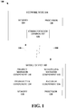
- a user equipment or mobile device 102 e.g., mobile device or other terminology
- a network node 104 e.g., an eNodeB, eNB, or other terminology.
- the mobile device 102 and/or the network node 104 can be in communication with other mobile devices (not shown) and/or other network nodes (not shown).
- a "link" is a communications channel that connects two or more devices or nodes.
- An uplink refers to a link used for transmission of signals from the mobile device 102 to the network node 104.
- a downlink (DL 108) refers to the link used for transmission of signals from the network node 104 to the mobile device 102. It is noted that although various aspects are discussed with respect to a single mobile device and a single network node, the various aspects discussed herein can be applied to one or more mobile devices and/or one or more network nodes.
- the mobile device 102 can include a priority manager component 110, a scheduling manager component 112, a transmitter component 114, and a receiver component 116.
- the transmitter component 114 and the receiver component 116 can be a single transmitter/receiver configured to transmit to and/or receive data to/from the network node 104, other network nodes, and/or other Mobile devices. Through the transmitter component 114 and the receiver component 116, the mobile device 102 can concurrently transmit and receive data, the mobile device 102 can transmit and receive data at different times, or combinations thereof.
- the priority manager component 110 can be configured to prioritize two or more UL data transmissions that are scheduled on, or overlap, at least a symbol of a TTI.
- the mobile device 102 can be configured to transmit (e.g., via the transmitter component 114) a first UL data transmission via a first TTI, a second UL data transmission via a second TTI, and subsequent UL data transmissions via subsequent TTIs.
- the second UL data transmission can overlap on at least one symbol with the first UL data transmission.
- the priority manager component 110 can determine which data transmission has a higher priority and, based on this determination, the scheduling manager component 112 can facilitate a scheduling of the first UL data transmission and the second UL data transmission.
- the scheduling manager component 112 can schedule the first UL data transmission according to a first priority level determined based on first DL control information (e.g., received by the receiver component 116). Further, the scheduling manager component 112 can schedule the second UL data transmission according to a second priority level determined based on second DL control information (e.g., received by the receiver component 116). For example, the priority manager component 110 can determine the second UL data transmission has a higher priority than the first UL transmission and, therefore, the scheduling manager component 112 can determine the scheduling of the second UL data transmission should override the scheduling of the first UL data transmission.
- the scheduling manager component 112 can schedule the first UL data transmission to override the schedule of the second UL data transmission.
- the priority manager component 110 can determine the respective priorities based on a first TTI length of the first UL data transmission and a second TTI length of the second UL data transmission. Further to this implementation, the scheduling manager component 112 can schedule the UL data transmission with the longer TTI length before the transmission of the UL data transmission with the shorted TTI length is scheduled.
- the scheduling manager component 112 can schedule the UL data transmission with the short TTI length before the transmission of the UL data transmission with the longer TTI length is scheduled. Further details related to controlling overlapping of multiple UL data transmissions for the mobile device 102 in TTI shortening will be described in further detail with respect to the following figures.
- the mobile device 102 can also include a memory 118 operatively coupled to a processor 120.
- the memory 118 can store protocols associated with UL transmission in shortened TTIs as discussed herein. Further, the memory 118 can facilitate action to control communication between the mobile device 102 and the network node 104, such that the non-limiting communications system 100 can employ stored protocols and/or algorithms to achieve improved communications in a wireless network as described herein.
- the mobile device 102 can include a control circuit and the processor 120 and the memory 118 can be installed on the control circuit. Further, the processor 120 can be configured to execute a program code stored in the memory 118 to perform the various aspects discussed herein.
- the network node 104 can include a communication component 122 that can be a transmitter/receiver configured to transmit to and/or receive data from the mobile device 102, other network nodes, and/or other mobile devices. Through the communication component 122, the network node 104 can concurrently transmit and receive data, the network node 104 can transmit and receive data at different times, or combinations thereof.
- the network node 104 can also comprise a memory 124 operatively coupled to a processor 126.
- the memory 124 can store protocols associated with UL transmission in shortened TTIs as discussed herein. Further, the memory 124 can facilitate action to control communication between the network node 104 and the mobile device 102, such that the non-limiting communications system 100 can employ stored protocols and/or algorithms to achieve improved communications in a wireless network as described herein.
- FIG. 2 illustrates an example, non-limiting communications system 200 for UL grant scheduling avoidance to mitigate overlapping symbols in accordance with one or more embodiments described herein. Repetitive description of like elements employed in other embodiments described herein is omitted for sake of brevity.
- the non-limiting communications system 200 can comprise one or more of the components and/or functionality of non-limiting communications system 100, and vice versa.
- the mobile device 102 can be dynamically (e.g., with a subframe to subframe granularity) scheduled with legacy TTI Physical Uplink Shared Channel (PUSCH) and/or shortened PUSCH (sPUSCH).
- PUSCH Physical Uplink Shared Channel
- sPUSCH shortened PUSCH
- the term "sPUSCH” refers to a PUSCH carrying data in a short UL TTI.
- the mobile device 102 can be dynamically (e.g., with a subframe to subframe granularity) scheduled with legacy TTI Physical Downlink Shared Channel (PDSCH) and/or shortened PDSCH (sPDSCH).
- sPDSCH refers to a PDSCH carrying data in a short TTI.
- the short TTI can be configured via higher layer.
- Each sTTI on the DL may contain a shortened Physical Downlink Control Channel (sPDCCH) decoding candidates.
- the sPDCCH can be designed for at least scheduling sPUSCH transmissions and/or sPDSCH transmissions. If a sPUSCH transmission is scheduled, the processing time for preparing UL data transmission upon UL grant reception at the mobile device 102 may be reduced. However, the processing time for legacy PUSCH may not be reduced, according to some implementations. Thus, it is possible that the UL data transmission with different TTI lengths may be scheduled to be transmitted in overlapped symbols.
- the mobile device 102 can include a monitor component 202 that can monitor incoming UL grant scheduling (e.g., PDCCH and/or sPDCCH).
- incoming UL grant scheduling e.g., PDCCH and/or sPDCCH.
- the monitor component 202 can determine when a second (or subsequent) UL grant scheduling arrives.
- an avoidance manager component 204 can selectively avoid the second (or subsequent) UL grant scheduling after a first UL grant scheduling is received.
- FIG. 3 illustrates a schematic representation 300 of frame structures for data transmissions in accordance with one or more embodiments described herein. Illustrated are sub frames of a DL 302 and sub frames of an UL 304.
- a first DL transmission that includes a PDCCH 306 can be received at the mobile device 102.
- the PDCCH 306 can schedule a first UL data transmission 308.
- the first UL data transmission 308 can occupy an entire subframe (e.g., subframe 4 in this example).
- a second DL transmission that includes a sPDCCH 310 can be received by the mobile device 102.
- the sPDCCH 310 can schedule a second UL data transmission 312.
- the second UL data transmission 312 overlaps symbols of the first UL data transmission 308.
- power issues can be induced by the overlapping symbols.
- the UL data transmission with different TTI lengths may be scheduled to be transmitted in overlapped frequency resources.
- the various aspects provided herein can assist to mitigate or avoid possible interference between UL data transmission with different TTI lengths.
- avoidance of a later UL grant scheduling can be facilitated by the avoidance manager component 204.
- the mobile device 102 e.g., the monitor component 202
- the mobile device 102 can skip monitoring some PDCCH/sPDCCH candidates.
- the candidates skipped can include candidates that might schedule a second UL data transmission overlapped on some symbol(s) with the first UL data transmission.
- the monitor component 202 can continue to monitor the PDCCH/sPDCCH candidates that can schedule a second UL data transmission overlapped on some symbol(s) with the first UL data transmission. However, the avoidance manager component 204 can selectively ignore the scheduling of the second UL data transmission if any PDCCH/sPDCCH scheduling the second UL data transmission overlapped on some symbol(s) with the first UL data transmission is detected.
- a reason for continuing to monitor the PDCCH/sPDCCH candidates by the monitor component 202 is to consider possible scheduling of DL assignment since the DL assignment and UL grant may have similar PDCCH/sPDCCH design (e.g. the same downlink control information size with one field to indicate DL assignment or UL grant).
- any later UL grant scheduling a second UL data transmission which overlaps in some symbols with a first UL data transmission scheduled by a previous UL grant can be ignored by the avoidance manager component 204.
- the first UL data transmission and the second UL data transmission can be on UL data channel in different TTI lengths.
- the first UL data transmission can be on PUSCH and the second UL data transmission can be on sPUSCH.
- the first UL data transmission can be on sPUSCH and the second UL data transmission can be on PUSCH.
- the first UL data transmission can be on sPUSCH in a first short TTI
- the second UL data transmission can be on sPUSCH in a second short TTI.
- FIG. 4 illustrates an example, non-limiting communications system 400 for utilizing later UL grant scheduling to mitigate overlapping symbols in accordance with one or more embodiments described herein. Repetitive description of like elements employed in other embodiments described herein is omitted for sake of brevity.
- the non-limiting communications system 400 can comprise one or more of the components and/or functionality of non-limiting communications system 100, and/or non-limiting communications system 200, and vice versa.
- later UL grant scheduling can be facilitated by an override manager component 402.
- the network node e.g., the eNB
- the monitor component 202 can continue to monitor the PDCCH/sPDCCH candidates which might schedule a second UL data transmission overlapped on some symbol(s) with the first UL data transmission.
- the first UL data transmission and the second UL data transmission may be on UL data channel in different TTI lengths.
- the first UL data transmission can be on PUSCH and the second UL data transmission can be on sPUSCH.
- the first UL data transmission can be on sPUSCH and the second UL data transmission can be on PUSCH.
- the first UL data transmission can be on sPUSCH in a first short TTI
- the second UL data transmission can be on sPUSCH in a second short TTI.
- the second UL data transmission and first UL data transmission can overlap in some frequency resources. If any PDCCH/sPDCCH scheduling the second UL data transmission is detected by the monitor component 202, the transmission priority between the scheduled second UL data transmission and the scheduled first UL data transmission could depend on the TTI length of the UL data channel. For example, the mobile device 102 can transmit sPUSCH instead of PUSCH.
- the mobile device 102 can transmit PUSCH instead of sPUSCH.
- the scheduling of the second UL data transmission can override the scheduling of the first UL data transmission as facilitated by the override manager component 402. Further, if the UL grant scheduling the UL data transmission with longer TTI overrides the UL grant scheduling the UL data transmission with shorter TTI, the mobile device 102 can transmit the UL data transmission with the longer TTI. If the UL grant scheduling the UL data transmission with shorter TTI overrides the UL grant scheduling the UL data transmission with longer TTI, the mobile device 102 can transmit the UL data transmission with short TTI.
- the UL data transmission with shorter TTI may be fully overlapped in time domain with the UL data transmission with longer TTI.
- the UL data transmission with short TTI can be partially overlapped in time domain with the UL data transmission with longer TTI.
- the mobile device does not transmit the overridden UL data transmission.
- the mobile device can transmit a third UL data transmission in the non-overlapped symbol(s) of the overridden UL data transmission.
- the mobile device can transmit a third UL data transmission in the non-overlapped symbol(s) of the overridden UL data transmission if the ratio of non-overlapped symbol(s) and overlapped symbol(s) of the overridden UL data transmission is larger than or equal to a threshold.
- the third UL data transmission can be punctured from the overridden UL data transmission.
- the transmission parameters e.g., Modulation and Coding Scheme (MCS), Hybrid Automatic Repeat Request (HARQ) process, Redundancy Version (RV), Transport Block Size (TBS), frequency resource allocation
- MCS Modulation and Coding Scheme
- HARQ Hybrid Automatic Repeat Request
- RV Redundancy Version
- TBS Transport Block Size
- frequency resource allocation e.g., frequency resource allocation
- MCS Modulation and Coding Scheme
- HARQ Hybrid Automatic Repeat Request
- RV Redundancy Version
- TBS Transport Block Size
- the HARQ process of the third UL data transmission can be the same as the overridden UL data transmission.
- the HARQ process of the third UL data transmission can be different from the first UL data transmission and the second UL data transmission.
- the RV of the third UL data transmission can be the same as the overridden UL data transmission.
- the RV of the third UL data transmission can be set to zero.
- the TBS of the third UL data transmission can be the same as the overridden UL data transmission.
- the TBS of the third UL data transmission can be derived at least from the number of the non-overlapped symbol(s) or the ratio of non-overlapped symbol(s) and overlapped symbol(s) of the overridden UL data transmission.
- the frequency resource allocation of the third UL data transmission can be the same as the overridden UL data transmission.
- the frequency resource allocation of the third UL data transmission can be determined from one of the frequency resource allocation of the first UL data transmission and the second UL data transmission. The determination might depend on the scheduled frequency resource size of the first UL data transmission and the second UL data transmission.
- the frequency resource allocation of the third UL data transmission can be the same as the frequency resource allocation with larger scheduled frequency resource size between the first UL data transmission and the second UL data transmission.
- the frequency resource allocation of the third UL data transmission can be the same as the frequency resource allocation with smaller scheduled frequency resource size between the first UL data transmission and the second UL data transmission.
- a first UL data transmission can be similar to the UL data transmission 308 of FIG. 3 , which occupies an entire subframe.
- a second UL data transmission 502 is transmitted by the mobile device 102 and a third UL data transmission 504 is transmitted by the mobile device 102.
- the first UL data transmission is the overridden UL data transmission.
- the third UL data transmission 504 overrides the first UL data transmission.
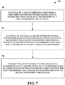
- FIG. 6 illustrates an example, non-limiting method 600 for uplink transmission in shortened TTIs in accordance with one or more embodiments described herein.
- a device comprising a processor can determine a first priority level of a first uplink data transmission based on first downlink control information related to scheduling the first uplink data transmission via a first TTI.
- the device can determine a second priority level of a second uplink data transmission based on second downlink control information related to scheduling the second uplink data transmission via a second TTI, wherein the second uplink data transmission overlaps at least a symbol with the first uplink data transmission.
- the device can transmit the first uplink data transmission or the second uplink data transmission based on a prioritization determined based on the first priority level and the second priority level, wherein the prioritization includes a first length of the first TTI and a second length of the second TTI.
- transmitting the first uplink data transmission or the second uplink data transmission comprises transmitting the first TTI for UL data transmission via the first TTI and transmitting the second TTI for UL data transmission via the second TTI.
- transmitting the first uplink data transmission or the second uplink data transmission can comprise transmitting the second uplink data transmission to override a scheduling of the first uplink data transmission based on a determination that the second priority level is prioritized before the first priority level.
- transmitting the first uplink data transmission or the second uplink data transmission can comprise transmitting the first uplink data transmission to override a scheduling of the second uplink data transmission based on a determination that the first priority level is prioritized before the second priority level.
- the prioritization can be based on the first length and the second length. Further to this implementation, transmitting the first uplink data transmission or the second uplink data transmission can comprise transmitting the second uplink data transmission to override a scheduling of the first uplink data transmission based on a determination that the second length is shorter than the first length. In some implementations, the mobile device does not transmit the first uplink data transmission that is overridden by the second uplink data transmission. In an alternative implementation, alternatively or additionally, the prioritization can be based on the first length and the second length.
- transmitting the first uplink data transmission or the second uplink data transmission can comprise transmitting the first uplink data transmission to override a scheduling of the second uplink data transmission based on a determination that the first length is shorter than the second length.
- the mobile device does not transmit the second uplink data transmission that is overridden by the first uplink data transmission.
- the prioritization can be based on the first length and the second length.
- transmitting the first uplink data transmission and the second uplink data transmission can comprise transmitting the second uplink data transmission to override a scheduling of the first uplink data transmission based on a determination that the second length is longer than the first length.
- the mobile device does not transmit the first uplink data transmission that is overridden by the second uplink data transmission. In some implementations, the mobile device does not transmit the first uplink data transmission that is overridden by the second uplink data transmission. According to yet another implementation, alternatively or additionally, the prioritization can be based on the first length and the second length. Further to this implementation, transmitting the first uplink data transmission or the second uplink data transmission can comprise transmitting the first uplink data transmission to override a scheduling of the second uplink data transmission based on a determination that the first length is longer than the second length. In some implementations, the mobile device does not transmit the second uplink data transmission that is overridden by the first uplink data transmission. FIG.
- a device comprising a processor, can receive a first downlink control information related to scheduling a first uplink data transmission via a first transmission time interval.
- the device can receive a second downlink control information related to scheduling a second uplink data transmission via a second transmission time interval.
- the second uplink data transmission can overlap at least a symbol with the first uplink data transmission.
- the device can transmit the first uplink data transmission and the second uplink data transmission based on a prioritization determined based on a first length of the first transmission time interval and a second length of the second transmission time interval.
- the prioritization can be based on the first length and the second length. Further to this implementation, transmitting the first uplink data transmission or the second uplink data transmission can comprise transmitting the second uplink data transmission to override a scheduling of the first uplink data transmission based on a determination that the second length is shorter than the first length. In an implementation, the mobile device does not transmit the first uplink data transmission that is overridden by the second uplink data transmission. In some implementations, the prioritization can be based on the first length and the second length.
- transmitting the first uplink data transmission or the second uplink data transmission comprises transmitting the first uplink data transmission to override a scheduling of the second uplink data transmission based on a determination that the first length is shorter than the second length.
- the mobile device does not transmit the second uplink data transmission that is overridden by the first uplink data transmission.
- FIG. 8 illustrates another example, non-limiting method 800 for uplink transmission in shortened TTIs in accordance with one or more embodiments described herein.
- a mobile device comprising a processor, can receive a first scheduling of a first uplink data transmission via a first transmission time interval based on a first downlink control information.
- the mobile device can receive a second scheduling of second uplink data transmission via a second transmission time interval based on a second downlink control information.
- the second uplink data transmission can overlap at least a symbol with the first uplink data transmission.
- the second downlink control information can be received after a receipt of the first downlink control information.
- the mobile device can transmit the second uplink data transmission.
- the second uplink data transmission can override a portion of the first uplink data transmission. According to an implementation, the mobile device does not transmit the portion of the first uplink data transmission that is overridden by the second uplink data transmission.
- the method can include transmitting, by the mobile device, a third uplink data transmission in a non-overlapped symbol of the portion of the first uplink data transmission that is overridden by the second uplink data transmission.
- the third uplink data transmission can be punctured from the portion of the first uplink data transmission that is overridden by the second uplink data transmission.
- a transmission parameter of the third uplink data transmission is derived from the first uplink data transmission that is overridden by the second uplink data transmission.
- the first uplink data transmission can comprise a first modulation and coding scheme and the third uplink data transmission can comprise a second modulation and coding scheme, wherein the first modulation and coding scheme and the second modulation and coding scheme are a same modulation and coding scheme.
- the first uplink data transmission can comprise a first hybrid automatic repeat request process and the third uplink data transmission can comprise a second hybrid automatic repeat request process, wherein the first hybrid automatic repeat request process and the second hybrid automatic repeat request process are a same hybrid automatic repeat request process.
- the first uplink data transmission comprises a first transport block size and the third uplink data transmission comprises a second transport block size, wherein the first transport block size and the second transport block size are a same transport block size.
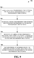
- FIG. 9 illustrates an example, non-limiting method 900 for a mobile device comprising a processor to skip monitoring a DL control channel after a first DL control information is received in accordance with one or more embodiments described herein.
- the method 900 starts at 902 when a first TTI for UL data transmission via the first TTI can be configured.
- a second TTI for UL data transmission via the second TTI can be configured at 904.
- the mobile device can receive a first DL control information for scheduling a first UL data transmission via the first TTI. Further, at 908, the mobile device can skip monitoring the DL control channel for scheduling a second UL data transmission via the second TTI. The scheduled second UL data transmission can overlap on some symbol(s) with the scheduled first UL data transmission.
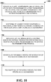
- FIG. 10 illustrates an example, non-limiting method 1000 for a mobile device to ignore scheduling of a second UL data transmission after receipt of a first UL data transmission in accordance with one or more embodiments described herein.
- a first TTI for UL data transmission via a first TTI and a second TTI for UL data transmission via a second TTI are configured.
- a first DL control information for scheduling a first UL data transmission is received by the mobile device at 1004.
- the mobile device receives, at 1006, a second DL control information for scheduling a second UL data transmission via the second TTI.
- the scheduled second UL data transmission overlaps on some symbol(s) with the scheduled first UL data transmission. Therefore, at 1008, the mobile device can ignore the scheduling of the second UL data transmission. Accordingly, at 1010, the mobile device can transmit the first UL data transmission.
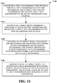
- FIG. 11 illustrates an example, non-limiting method 1100 for a mobile device comprising a processor for improved uplink transmission in shortened transmission time intervals in accordance with one or more embodiments described herein.
- the method 1100 starts at 1102 when a first TTI for an UL data transmission via the first TTI and a second TTI for UL data transmission via the second TTI are configured.
- a first DL control information for scheduling a first UL data transmission via the first TTI is received, by a mobile device comprising a processor, at 1104.
- a second DL control information for scheduling a second UL data transmission via the second TTI is received by the mobile device at 1106.
- the scheduled second UL data transmission overlaps on some symbol(s) with the scheduled first UL data transmission.
- the mobile device transmits the scheduled UL data transmission with higher priority.
- the prioritization depends on the TTI length of the first UL data transmission and the second UL data transmission.
- the scheduling of UL data transmission with higher priority overrides the scheduling of the UL data transmission with lower priority.
- the mobile device can transmit the scheduled UL data transmission with longer TTI length.
- the scheduling of the UL data transmission with longer TTI length overrides the scheduling of the UL data transmission with a shorter TTI length.
- the mobile device can transmit the scheduled UL data transmission with shorter TTI length.
- the scheduling of the UL data transmission with shorter TTI length can override the scheduling of the UL data transmission with longer TTI length.
- FIG. 12 illustrates another example, non-limiting method 1200 for a mobile device comprising a processor for improved uplink transmission in shortened transmission time intervals in accordance with one or more embodiments described herein.
- the method starts, at 1202, when a first TTI for scheduling UL data transmission via the first TTI and a second TTI for scheduling UL data transmission via the second TTI are configured.
- a mobile device comprising a processor can receive a first DL control information for scheduling a first UL data transmission via the first TTI.
- the mobile device can receive a second DL control information for scheduling a second UL data transmission via the second TTI.
- the scheduled second UL data transmission overlaps on some symbol(s) with the scheduled first UL data transmission.
- the mobile device can transmit the second UL data transmission wherein the scheduling of the second UL data transmission overrides the scheduling of the first UL data transmission.
- the second DL control information for scheduling the second UL data transmission is received at later timing than the first DL control information for scheduling the first UL data transmission.
- the mobile device can monitor the DL control channel for scheduling a second UL data transmission via the second TTI wherein the scheduled second UL data transmission overlaps on some symbol(s) with the scheduled first UL data transmission.
- scheduling of the UL data transmission with the longer TTI length overrides the scheduling of the UL data transmission with the shorter TTI length.
- the mobile device can transmit the UL data transmission with the longer TTI.
- the mobile device can transmit the UL data transmission with short TTI.
- the scheduled first UL data transmission via the first TTI and the scheduled second UL data transmission via the second TTI are partially overlapped in time domain.
- the UL data transmission with shorter TTI is fully overlapped in time domain with the UL data transmission with longer TTI.
- the mobile device does not transmit the overridden UL data transmission.
- the mobile device can transmit a third UL data transmission in the non-overlapped symbol(s) of the overridden UL data transmission. In some implementations, the mobile device can transmit a third UL data transmission in the non-overlapped symbol(s) of the overridden UL data transmission if the ratio of non-overlapped symbol(s) and overlapped symbol(s) of the overridden UL data transmission is larger than or equal to a threshold. According to some implementations, the third UL data transmission is punctured from the overridden UL data transmission. In an implementation, the transmission parameters of the third UL data transmission are derived at least from the overridden UL data transmission. According to some implementation, the MCS of the third UL data transmission is the same as the overridden UL data transmission.
- the MCS of the third UL data transmission is derived from at least the MCS of the overridden UL data transmission and/or the ratio of non-overlapped symbol(s) and overlapped symbol(s) of the overridden UL data transmission.
- the HARQ process of the third UL data transmission is the same as the overridden UL data transmission.
- the HARQ process of the third UL data transmission is different from the first UL data transmission via the first TTI and the second data transmission via the second TTI.
- the RV of the third UL data transmission is the same as the overridden UL data transmission.
- the RV of the third UL data transmission is set to zero.
- the TBS of the third UL data transmission is the same as the overridden UL data transmission.
- the TBS of the third UL data transmission is derived at least from the number of the non-overlapped symbol(s) or the ratio of non-overlapped symbol(s) and overlapped symbol(s) of the overridden UL data transmission.
- the frequency resource allocation of the third UL data transmission is the same as the overridden UL data transmission. According to an implementation, the frequency resource allocation of the third UL data transmission is determined from one of the frequency resource allocation of the first UL data transmission and the second UL data transmission.
- the determination of the frequency resource allocation of the third UL data transmission depends on the scheduled frequency resource size of the first UL data transmission and the second UL data transmission.
- the frequency resource allocation of the third UL data transmission can be the same as the frequency resource allocation with larger scheduled frequency resource size between the first UL data transmission and the second UL data transmission, in accordance with some implementations.
- the frequency resource allocation of the third UL data transmission can be the same as the frequency resource allocation with smaller scheduled frequency resource size between the first UL data transmission and the second UL data transmission, according to some implementations.
- the TTI length of the first TTI and the second TTI can be different, according to an implementation. In another implementation, the TTI length of the first TTI can be longer than the TTI length of the second TTI.
- the TTI length of the first TTI is one subframe and the first UL data transmission is on PUSCH.
- the TTI length of the second TTI is one of 1/2/3/4/7 symbol TTIs and the second UL data transmission is on sPUSCH.
- the TTI length of the second TTI is longer than the TTI length of the first TTI.
- the TTI length of the second TTI is one subframe and the second UL data transmission is on PUSCH.
- the TTI length of the first TTI is one of 1/2/3/4/7 symbol TTIs and the first UL data transmission is on sPUSCH.
- the TTI length of the first TTI is one of 1/2/3/4/7 symbol TTIs and the first UL data transmission is on sPUSCH.
- the TTI length of the second TTI is one of 1/2/3/4/7 symbol TTIs and the second UL data transmission is on sPUSCH.
- the scheduled second UL data transmission and the scheduled first UL data transmission overlap in some frequency resources.
- the study item aims to investigate and standardize techniques of latency reduction.
- the objective of the study item is to study enhancements to the Evolved Universal Terrestrial Radio Access Network (E-UTRAN) radio system in order to significantly reduce the packet data latency over the LTE Uu air interface (e.g., an air interface between a mobile device and a base station device) for an active mobile device and significantly reduce the packet data transport round trip latency for mobile devices that have been inactive for a longer period (in connected state).
- the study area includes resource efficiency, including air interface capacity, battery lifetime, control channel resources, specification impact and technical feasibility.
- FDD frequency division duplex
- TDD time division duplex
- RRC radio resource control
- TTI shortening and processing time reduction can be considered as an effective solution for reducing latency, as the time unit for transmission can be reduced e.g., from 1 ms (14 OFDM) symbol to 1 ⁇ 7 OFDM symbols and the delay caused by decoding can be reduced as well.
- reducing the length of TTI may also have significant impact to current system design as the physical channels are developed based on 1 ms structure.
- control channels in LTE there are two types of control channel, one of them is physical downlink control channel (PDCCH), which is a wide band signal across whole system bandwidth and occupying the first several (e.g., 1 ⁇ 4) OFDM symbols of 1 ms subframe.
- PDCCH physical downlink control channel
- ePDCCH Enhanced Physical Downlink Control Channel
- PHICH duration is signaled by higher layers according to Table 6.9.3-1 in 3GPP TR 36.211 V13.1.0, "E-UTRA Study on latency reduction techniques for LTE (Release 13) .”
- the duration signaled puts a lower limit on the size of the control region determined from the control format indicator (CFI).
- CFI control format indicator
- N RB DL > 10 if extended Physical Hybrid-ARQ Indicator Channel (PHICH) duration is indicated by higher layers then the mobile device shall assume that CFI is equal to PHICH duration.
- a mobile device may assume that CFI is equal to the value of the higher layer parameter non-MBSFNregionLength , as described in 3GPP TS 36.331, "Evolved Universal Terrestrial Radio Access (E-UTRA); Radio Resource Control (RRC) protocol specification .”
- E-UTRA Evolved Universal Terrestrial Radio Access
- RRC Radio Resource Control
- the physical control format indicator channel carries information about the number of OFDM symbols used for transmission of PDCCHs in a subframe.
- the set of OFDM symbols possible to use for PDCCH in a subframe is given by Table 6.7-1.
- Table 6.7-1 Number of OFDM symbols used for PDCCH Subframe Number of OFDM symbols for PDCCH when N RB DL > 10 Number of OFDM symbols for PDCCH when N RB DL ⁇ 10
- the mobile device may assume the PCFICH is transmitted when the number of OFDM symbols for PDCCH is greater than zero unless stated otherwise in 3GPP TS 36.212: "Evolved Universal Terrestrial Radio Access (E-UTRA); Multiplexing and channel coding," clause 12.
- E-UTRA Evolved Universal Terrestrial Radio Access
- Resource-element groups are used for defining the mapping of control channels to resource elements.
- a resource-element group is represented by the index pair ( k' , l' ) of the resource element with the lowest index k in the group with all resource elements in the group having the same value of l .
- Mapping of a symbol-quadruplet ⁇ z ( i ), z ( i + 1), z ( i + 2), z ( i + 3) ⁇ onto a resource-element group represented by resource-element ( k' , l' ) is defined such that elements z ( i ) are mapped to resource elements ( k , l ) of the resource-element group not used for cell-specific reference signals in increasing order of i and k .
- cell-specific reference signals shall be assumed to be present on antenna ports 0 and 1 for the purpose of mapping a symbol-quadruplet to a resource-element group, otherwise the number of cell-specific reference signals shall be assumed equal to the actual number of antenna ports used for cell-specific reference signals.
- the mobile device shall not make any assumptions about resource elements assumed to be reserved for reference signals but not used for transmission of a reference signal. For frame structure type 3, if the higher layer parameter subframeStartPosition indicates 's07' and the downlink transmission starts in the second slot of a subframe, the above definition applies to the second slot of that subframe instead of the first slot.
- Section 6.2.4A Enhanced Resource-Element Groups (EREGs) of 3GPP TR 36.211 V13.1.0, "E-UTRA Study on latency reduction techniques for LTE (Release 13)" states:
- the enhanced physical downlink control channel (EPDCCH) carries scheduling assignments.
- An enhanced physical downlink control channel is transmitted using an aggregation of one or several consecutive enhanced control channel elements (ECCEs) where each ECCE consists of multiple enhanced resource element groups (EREGs), defined in clause 6.2.4A.
- ECCEs enhanced control channel elements
- EREGs enhanced resource element groups
- the number of ECCEs used for one EPDCCH depends on the EPDCCH format as given by Table 6.8A.1-2 and the number of EREGs per ECCE is given by Table 6.8A.1-1.Both localized and distributed transmission is supported.
- An EPDCCH can use either localized or distributed transmission, differing in the mapping of ECCEs to EREGs and PRB pairs.
- a mobile device shall monitor multiple EPDCCHs as defined in 3GPP TS 36.213 (3GPP TS 36.212: "Evolved Universal Terrestrial Radio Access (E-UTRA); Multiplexing and channel coding ".
- E-UTRA Evolved Universal Terrestrial Radio Access
- One or two sets of physical resource-block pairs which a mobile device shall monitor for EPDCCH transmissions can be configured. All EPDCCH candidates in EPDCCH set X m use either only localized or only distributed transmission as configured by higher layers.
- Table 6.8A.1-1 Number of EREGs per ECCE, N EREG ECCE Normal cyclic prefix Extended cyclic prefix Normal subframe Special subframe, configuration 3, 4, 8 Special subframe, configuration 1, 2, 6, 7, 9 Normal subframe Special subframe, configuration 1, 2, 3, 5, 6 4 8
- Table 6.8A.1-2 Supported EPDCCH formats EPDCCH format Number of ECCEs for one EPDCCH, N ECCE EPDCCH Case A Case B Localized transmission Distributed transmission Localized transmissi on Distributed transmission 0 2 2 1 1 1 4 4 2 2 2 8 8 4 4 3 16 16 8 8 4 - 32 - 16 Case A in Table 6.8A.1-2 is used when the conditions corresponding to case 1 in clause 9.1.4 of 3GPP TS 36.212 V13.1.0, "E-UTRA Multiplexing and channel coding (Release 13) " are satisfied, otherwise case B is used.
- n EPDCCH for a particular mobile device and referenced in 3GPP TS 36.212 V13.1.0, "E-UTRA Multiplexing and channel coding (Release 13) ,” is defined as the number of downlink resource elements ( k , l ) available for EPDCCH transmission in a physical resource-block pair configured for possible EPDCCH transmission of EPDCCH set X 0 and fulfilling all of the following criteria: they are part of any one of the 16 EREGs in the physical resource-block pair, and they are assumed by the mobile device not to be used for cell-specific reference signals, where the positions of the cell-specific reference signals are given by clause 6.10.1.2 with the number of antenna ports for and the frequency shift of cell-specific reference signals derived as described in clause 6.10.1.2 unless other values for these parameters are provided by clause 9.1.4.3 in 3GPP TS 36.212 V13.1.0, "E-UTRA Multiplexing and channel coding (Release 13) ,” and they are assumed by the mobile device not to be used for transmission of CSI
- downlink control information can be carried on a control channel (e.g. PDCCH/ePDCCH).
- Downlink control information can be used to carry scheduling for downlink data or uplink data.
- Downlink control information can also be used carry special messages, (e.g. triggering some procedure or control mobile device power), from eNB to the UE.
- special messages e.g. triggering some procedure or control mobile device power
- DCI for downlink data scheduling can comprise the resource allocation(in the frequency domain), modulation and coding scheme, redundancy version, HARQ process ID, and other information require to perform the reception. More detail example can be found in the below quotation from 3GPP TS 36.212 V13.1.0, "E-UTRA Multiplexing and channel coding (Release 13) ":
- the following information is transmitted by means of the DCI format 2D: Carrier indicator - 0 or 3 bits.
- the field is present according to the definitions in 3GPP TS 36.211: "Evolved Universal Terrestrial Radio Access (E-UTRA); Physical channels and modulation .”
- Resource allocation header (resource allocation type 0 / type 1) - 1 bit as defined in section 7.1.6 of 3GPP TS 36.211: "Evolved Universal Terrestrial Radio Access (E-UTRA); Physical channels and modulation .” If downlink bandwidth is less than or equal to 10 PRBs, there is no resource allocation header and resource allocation type 0 is assumed.
- Resource block assignment For resource allocation type 0 as defined in section 7.1.6.1 of 3GPP TS 36.211: "Evolved Universal Terrestrial Radio Access (E-UTRA); Physical channels and modulation " ⁇ N RB DL / P ⁇ bits provide the resource allocation.
- E-UTRA Evolved Universal Terrestrial Radio Access
- SRS request - [0-1] bit This field can only be present for TDD operation and if present is defined in section 8.2 of 3GPP TS 36.211: "Evolved Universal Terrestrial Radio Access (E-UTRA); Physical channels and modulation .”
- E-UTRA Evolved Universal Terrestrial Radio Access
- Physical channels and modulation e.g., Physical channels and modulation .
- Modulation and coding scheme - 5 bits as defined in section 7.1.7 of 3GPP TS 36.211: "Evolved Universal Terrestrial Radio Access (E-UTRA); Physical channels and modulation ;” New data indicator - 1 bit; Redundancy version - 2 bits.
- E-UTRA Evolved Universal Terrestrial Radio Access
- Physical channels and modulation Physical channels and modulation ;
- HARQ-ACK resource offset this field is present when this format is carried by EPDCCH.
- This field is not present when this format is carried by PDCCH) - 2 bits as defined in section 10.1 of 3GPP TS 36.211: "Evolved Universal Terrestrial Radio Access (E-UTRA); Physical channels and modulation .”
- the 2 bits are set to 0 when this format is carried by EPDCCH on a secondary cell, or when this format is carried by EPDCCH on the primary cell scheduling PDSCH on a secondary cell and the mobile device is configured with PUCCH format 3 for HARQ-ACK feedback. If both transport blocks are enabled; transport block 1 is mapped to codeword 0; and transport block 2 is mapped to codeword 1. In case one of the transport blocks is disabled; the transport block to codeword mapping is specified according to Table 5.3.3.1.5-2.
- Value 4, 5, 6 in Table 5.3.3.1.5C-1 are only supported for retransmission of the corresponding transport block if that transport block has previously been transmitted using two, three or four layers, respectively. If the number of information bits in format 2D carried by PDCCH belongs to one of the sizes in Table 5.3.3.1.2-1, one zero bit shall be appended to format 2D.
- the mobile device should decode several decoding candidates without knowing which or whether the candidate(s) exist.
- This type of decoding is referred to as blind decoding.
- the resource of decoding candidate(s) is known as a search space of a UE.
- the search space is further partition to common search space and mobile device specific search space which may contain different type of messages.
- mobile device may search for different DCI format.
- mobile device can monitor control channel addressed different identifier (e.g.
- Radio Network Temporary Identifier (RNTI)
- RNTI Radio Network Temporary Identifier
- the control region of each serving cell consists of a set of CCEs, numbered from 0 to N CCE, k -1 according to subclause 6.8.1 in 3GPP TS 36.211: "Evolved Universal Terrestrial Radio Access (E-UTRA); Physical channels and modulation ," where N CCE, k is the total number of CCEs in the control region of subframe k .
- the mobile device shall monitor a set of PDCCH candidates on one or more activated serving cells as configured by higher layer signaling for control information, where monitoring implies attempting to decode each of the PDCCHs in the set according to all the monitored DCI formats.
- a BL/CE mobile device is not required to monitor PDCCH.
- the set of PDCCH candidates to monitor are defined in terms of search spaces, where a search space S k L at aggregation level L ⁇ ⁇ 1,2,4,8 ⁇ is defined by a set of PDCCH candidates.
- m' m .
- the carrier indicator field value corresponds to cif-InSchedulingCell-r13 , otherwise, the carrier indicator field value is the same as ServCellIndex given in 3GPP TS 36.331, "Evolved Universal Terrestrial Radio Access (E-UTRA); Radio Resource Control (RRC) protocol specification.”
- E-UTRA Evolved Universal Terrestrial Radio Access
- RRC Radio Resource Control
- the mobile device shall monitor one common search space in every non-DRX subframe at each of the aggregation levels 4 and 8 on the primary cell.
- a mobile device shall monitor common search space on a cell to decode the PDCCHs necessary to receive MBMS on that cell when configured by higher layers.
- a mobile device If a mobile device is not configured for EPDCCH monitoring, and if the mobile device is not configured with a carrier indicator field, then the mobile device shall monitor one PDCCH UE-specific search space at each of the aggregation levels 1, 2, 4, 8 on each activated serving cell in every non-DRX subframe. If a mobile device is not configured for EPDCCH monitoring, and if the mobile device is configured with a carrier indicator field, then the mobile device shall monitor one or more UE-specific search spaces at each of the aggregation levels 1, 2, 4, 8 on one or more activated serving cells as configured by higher layer signaling in every non-DRX subframe.
- a mobile device If a mobile device is configured for EPDCCH monitoring on a serving cell, and if that serving cell is activated, and if the mobile device is not configured with a carrier indicator field, then the mobile device shall monitor one PDCCH UE-specific search space at each of the aggregation levels 1, 2, 4, 8 on that serving cell in all non-DRX subframes where EPDCCH is not monitored on that serving cell.
- a mobile device is configured for EPDCCH monitoring on a serving cell, and if that serving cell is activated, and if the mobile device is configured with a carrier indicator field, then the mobile device shall monitor one or more PDCCH UE-specific search spaces at each of the aggregation levels 1, 2, 4, 8 on that serving cell as configured by higher layer signaling in all non-DRX subframes where EPDCCH is not monitored on that serving cell.
- the common and PDCCH UE-specific search spaces on the primary cell may overlap.
- a mobile device configured with the carrier indicator field associated with monitoring PDCCH on serving cell c shall monitor PDCCH configured with carrier indicator field and with CRC scrambled by C-RNTI in the PDCCH mobile device specific search space of serving cell c .
- a mobile device configured with the carrier indicator field associated with monitoring PDCCH on the primary cell shall monitor PDCCH configured with carrier indicator field and with CRC scrambled by SPS C-RNTI in the PDCCH mobile device specific search space of the primary cell.
- the mobile device shall monitor the common search space for PDCCH without carrier indicator field.
- the mobile device if the mobile device is not configured with a carrier indicator field, it shall monitor the PDCCH mobile device specific search space for PDCCH without carrier indicator field, if the mobile device is configured with a carrier indicator field it shall monitor the PDCCH mobile device specific search space for PDCCH with carrier indicator field.
- the mobile device is not expected to monitor the PDCCH of a secondary cell if it is configured to monitor PDCCH with carrier indicator field corresponding to that secondary cell in another serving cell. If the mobile device is configured with a LAA Scell, the mobile device is not expected to monitor the PDCCH mobile device specific space of the LAA SCell if it is configured to monitor PDCCH with carrier indicator field corresponding to that LAA Scell in another serving cell, where the mobile device is not expected to be configured to monitor PDCCH with carrier indicator field in an LAA Scell; where the mobile device is not expected to be scheduled with PDSCH starting in the second slot in a subframe in an LAA Scell if the mobile device is configured to monitor PDCCH with carrier indicator field corresponding to that LAA Scell in another serving cell.
- the mobile device shall monitor PDCCH candidates at least for the same serving cell.
- PDCCH mobile device specific search space on the primary cell shall assume that for the PDCCH candidates with CRC scrambled by C-RNTI or SPS C-RNTI, if the mobile device is configured with the carrier indicator field associated with monitoring the PDCCH on the primary cell, only the PDCCH in the common search space is transmitted by the primary cell; otherwise, only the PDCCH in the mobile device specific search space is transmitted by the primary cell.
- a mobile device configured to monitor PDCCH candidates in a given serving cell with a given DCI format size with CIF, and CRC scrambled by C- RNTI, where the PDCCH candidates may have one or more possible values of CIF for the given DCI format size, shall assume that a PDCCH candidate with the given DCI format size can be transmitted in the given serving cell in any PDCCH mobile device specific search space corresponding to any of the possible values of CIF for the given DCI format size.
- a serving cell is a LAA Scell
- the mobile device monitors PDCCH UE-specific search space candidates on the Scell in both the first and second slots of a subframe, and the aggregation levels defining the search spaces are listed in Table 9.1.1-1A; otherwise, the aggregation levels defining the search spaces are listed in Table 9.1.1-1.
- the mobile device may receive PDCCH with DCI CRC scrambled by CC-RNTI as described in subclause 13A on the LAA Scell.
- the DCI formats that the mobile device shall monitor depend on the configured transmission mode per each serving cell as defined in subclause 7.1. If a mobile device is configured with higher layer parameter skipMonitoringDCI-format0-1A for a serving cell, the mobile device is not required to monitor the PDCCH with DCI Format 0/1A in the mobile device specific search space for that serving cell.
- M L round a ⁇ M full L , where the value of a is determined according to Table 9.1.1-2 and M full L is determined according to Table 9.1.1-1 by replacing M ( L ) with M full L .
- Table 9.1.1-1 PDCCH candidates monitored by a UE Search space S k L Number of PDCCH candidates M ( L ) Type Aggregation level L Size [in CCEs] UE-specific 1 6 6 2 12 6 4 8 2 8 16 2 Common 4 16 4 8 16 2 Table 9.1.1-1A: PDCCH UE-specific search space candidates monitored by a mobile device on LAA Scell Search space S k L Number of PDCCH candidates M ( L ) in first slot Number of PDCCH candidates M ( L ) in second slot Type Aggregation level L Size [in CCEs] UE-specific 1 6 6 6 2 12 6 6 4 8 2 2 8 16 2 2 Table 9.1.1-2: Scaling factor for PDCCH candidates reduction pdcch-candidateReductions Value of a 0 0 1 0.33 2 0.66 3 1
- the RNTI value used for n RNTI is defined in subclause 7.1 in downlink and subclause 8 in uplink.
- higher layer signaling can configure a mobile device with one or two EPDCCH-PRB-sets for EPDCCH monitoring.
- the PRB-pairs corresponding to an EPDCCH-PRB-set are indicated by higher layers as described in subclause 9.1.4.4.
- Each EPDCCH-PRB-set consists of set of ECCEs numbered from 0 to N ECCE, p , k -1 where N ECCE, p , k is the number of ECCEs in EPDCCH-PRB-set p of subframe k.
- Each EPDCCH-PRB-set can be configured for either localized EPDCCH transmission or distributed EPDCCH transmission.
- the mobile device shall monitor a set of EPDCCH candidates on one or more activated serving cells as configured by higher layer signaling for control information, where monitoring implies attempting to decode each of the EPDCCHs in the set according to the monitored DCI formats.
- a BL/CE mobile device is not required to monitor EPDCCH.
- the set of EPDCCH candidates to monitor are defined in terms of EPDCCH UE-specific search spaces. For each serving cell, the sub frames in which the mobile device monitors EPDCCH UE-specific search spaces are configured by higher layers.
- the mobile device shall not monitor EPDCCH
- E-UTRA Evolved Universal Terrestrial Radio Access
- Physical channels and modulation For TDD and extended downlink CP, in special subframes for the special subframe configurations 0, 4 and 7 shown in Table 4.2-1 of 3GPP TS 36.211: "Evolved Universal Terrestrial Radio Access (E-UTRA); Physical channels and modulation.”
- E-UTRA Evolved Universal Terrestrial Radio Access
- An EPDCCH UE-specific search space ES k L at aggregation level L ⁇ ⁇ 1,2,4,8,16,32 ⁇ is defined by a set of EPDCCH candidates.
- the ECCEs corresponding to EPDCCH candidate m of the search space ES k L are given by L Y p , k + ⁇ m ⁇ N ECCE , p , k L ⁇ M p L ⁇ + b mod ⁇ N ECCE , p , k / L ⁇ + i
- a mobile device is configured with higher layer parameter pdcch-candidateReductions for a specific search space at aggregation level L in EPDCCH-PRB-set p for a serving cell
- the carrier indicator field value corresponds to cif-InSchedulingCell-r13 , otherwise the carrier indicator field value is the same as ServCellIndex given in 3GPP TS36.331, "Evolved Universal Terrestrial Radio Access (E-UTRA); Radio Resource Control (RRC) protocol specification.”
- E-UTRA Evolved Universal Terrestrial Radio Access
- RRC Radio Resource Control
- a mobile device is not expected to monitor an EPDCCH candidate, if an ECCE corresponding to that EPDCCH candidate is mapped to a PRB pair that overlaps in frequency with a transmission of either PBCH or primary or secondary synchronization signals in the same subframe.
- n ID i EPDCCH value
- n ID i EPDCCH is defined in subclause 6.10.3A.1 in 3GPP TS 36.211: "Evolved Universal Terrestrial Radio Access (E-UTRA); Physical channels and modulation.”
- the mobile device receives an EPDCCH candidate with a given DCI payload size corresponding to one of the EPDCCH-PRB-sets and mapped only to a given set of REs (as described in subclause 6.8A.5 in 3GPP TS 36.211: “Evolved Universal Terrestrial Radio Access (E-UTRA); Physical channels and modulation.”
- the mobile device is also configured to monitor an EPDCCH candidate with the same DCI payload size and corresponding to the other EPDCCH-PRB-set and which is mapped only to the same set of REs, and if the number of the first ECCE of the received EPDCCH candidate
- Y p,k A p ⁇ Y p , k ⁇ 1 mod D
- the RNTI value used for n RNTI is defined in subclause 7.1 in downlink and subclause 8 in uplink.
- the DCI formats that the mobile device shall monitor depend on the configured transmission mode per each serving cell as defined in subclause 7.1.
- a mobile device is configured with higher layer parameter skipMonitoringDCI-format0-1A for a serving cell, the mobile device is not required to monitor the EPDCCH with DCI Format 0/1A in the mobile device specific search space for that serving cell.
- a serving cell is a LAA Scell, and if the higher layer parameter subframeStartPosition for the Scell indicates 's07' - the mobile device monitors EPDCCH UE-specific search space candidates on the Scell assuming they start in both the first slot and the second slot of a subframe.
- the aggregation levels defining the search spaces and the number of monitored EPDCCH candidates is given as follows: For a mobile device configured with only one EPDCCH-PRB-set for distributed transmission, the aggregation levels defining the search spaces and the number of monitored EPDCCH candidates are listed in Table 9.1.4-1a, Table 9.1.4-1b. For a mobile device configured with only one EPDCCH-PRB-set for localized transmission, the aggregation levels defining the search spaces and the number of monitored EPDCCH candidates are listed in Table 9.1.4-2a, Table 9.1.4-2b.
- the aggregation levels defining the search spaces and the number of monitored EPDCCH candidates are listed in Table 9.1.4-3a, 9.1.4-3b.
- the aggregation levels defining the search spaces and the number of monitored EPDCCH candidates are listed in Table 9.1.4-4a, 9.4.4-4b.
- the aggregation levels defining the search spaces and the number of monitored EPDCCH candidates are listed in Table 9.1.4-5a, 9.1.4-5b.
- Section 7.1 UE procedure for receiving the physical downlink shared channel of 3GPP TS 36.213 vl3.1.1, "E-UTRA Physical layer procedures (Release 13)" states:
- a mobile device shall: upon detection of a PDCCH of the serving cell with DCI format 1, 1A, 1B, 1C, 1D, 2, 2A, 2B, 2C, or 2D intended for the mobile device in a subframe, or upon detection of an EPDCCH of the serving cell with DCI format 1, 1A, 1B, 1D, 2, 2A, 2B, 2C, or 2D intended for the mobile device in a subframe decode the corresponding PDSCH in the same subframe with the restriction of the number of transport blocks defined in the higher layers.
- a mobile device is configured by higher layers to decode PDCCH with CRC scrambled by the SI-RNTI, the mobile device shall decode the PDCCH and the corresponding PDSCH according to any of the combinations defined in Table 7.1-1.
- the scrambling initialization of PDSCH corresponding to these PDCCHs is by SI-RNTI.
- DCI format Search Space Transmission scheme of PDSCH corresponding to PDCCH DCI format 1C Common If the number of PBCH antenna ports is one, Single-antenna port, port 0 is used (see subclause 7.1.1), otherwise Transmit diversity (see subclause 7.1.2). DCI format 1A Common If the number of PBCH antenna ports is one, Single-antenna port, port 0 is used (see subclause 7.1.1), otherwise Transmit diversity (see subclause 7.1.2).
- a mobile device If a mobile device is configured by higher layers to decode PDCCH with CRC scrambled by the P-RNTI, the mobile device shall decode the PDCCH and the corresponding PDSCH according to any of the combinations defined in Table 7.1-2.
- the scrambling initialization of PDSCH corresponding to these PDCCHs is by P-RNTI. If a mobile device is configured by higher layers to decode MPDCCH with CRC scrambled by the P-RNTI, the mobile device shall decode the MPDCCH and any corresponding PDSCH according to any of the combinations defined in Table 7.1-2A.
- the scrambling initialization of PDSCH corresponding to these MPDCCHs is by P-RNTI.
- the mobile device is not required to monitor PDCCH with CRC scrambled by the P-RNTI on the PSCell.
- Table 7.1-2 PDCCH and PDSCH configured by P-RNTI DCI format Search Space Transmission scheme of PDSCH corresponding to PDCCH DCI format 1C Common If the number of PBCH antenna ports is one, Single-antenna port, port 0 is used (see subclause 7.1.1), otherwise Transmit diversity (see subclause 7.1.2) DCI format 1A Common If the number of PBCH antenna ports is one, Single-antenna port, port 0 is used (see subclause 7.1.1), otherwise Transmit diversity (see subclause 7.1.2)
- a mobile device If a mobile device is configured by higher layers to decode PDCCH with CRC scrambled by the RA-RNTI, the mobile device shall decode the PDCCH and the corresponding PDSCH according to any of the combinations defined in Table 7.1-3.
- the scrambling initialization of PDSCH corresponding to these PDCCHs is by RA-RNTI. If a mobile device is configured by higher layers to decode MPDCCH with CRC scrambled by the RA-RNTI, the mobile device shall decode the MPDCCH and the corresponding PDSCH according to any of the combinations defined in Table 7.1-3A.
- the scrambling initialization of PDSCH corresponding to these MPDCCHs is by RA-RNTI.
- the mobile device When RA-RNTI and either C-RNTI or SPS C-RNTI are assigned in the same subframe, the mobile device is not required to decode a PDSCH on the primary cell indicated by a PDCCH/EPDCCH with a CRC scrambled by C-RNTI or SPS C-RNTI.
- Table 7.1-3 PDCCH and PDSCH configured by RA-RNTI DCI format Search Space Transmission scheme of PDSCH corresponding to PDCCH DCI format 1C Common If the number of PBCH antenna ports is one, Single-antenna port, port 0 is used (see subclause 7.1.1), otherwise Transmit diversity (see subclause 7.1.2) DCI format 1A Common If the number of PBCH antenna ports is one, Single-antenna port, port 0 is used (see subclause 7.1.1), otherwise Transmit diversity (see subclause 7.1.2)
- the mobile device is semi-statically configured via higher layer signaling to receive PDSCH data transmissions signaled via PDCCH/EPDCCH according to one of the transmission modes, denoted mode 1 to mode 10. If a mobile device is configured by higher layers to decode PDCCH with CRC scrambled by the C-RNTI, the mobile device shall decode the PDCCH and any corresponding PDSCH according to the respective combinations defined in Table 7.1-5. The scrambling initialization of PDSCH corresponding to these PDCCHs is by C-RNTI.
- a mobile device If a mobile device is configured by higher layers to decode EPDCCH with CRC scrambled by the C-RNTI, the mobile device shall decode the EPDCCH and any corresponding PDSCH according to the respective combinations defined in Table 7.1-5A.
- the scrambling initialization of PDSCH corresponding to these EPDCCHs is by C-RNTI.
- the mobile device When a mobile device is configured in transmission mode 9 or 10, in the downlink subframes indicated by the higher layer parameter mbsfn-SubframeConfigList or by mbsfn-SubframeConfigList-v12x0 or by laa-SCellSubframeConfig of serving cell c except in subframes for the serving cell : indicated by higher layers to decode PMCH or, configured by higher layers to be part of a positioning reference signal occasion and the positioning reference signal occasion is only configured within MBSFN subframes and the cyclic prefix length used in subframe #0 is normal cyclic prefix, the mobile device shall upon detection of a PDCCH with CRC scrambled by the C-RNTI with DCI format 1A/2C/2D intended for the mobile device or, upon detection of an EPDCCH with CRC scrambled by the C-RNTI with DCI format 1A/2C/2D intended for the mobile device, decode the corresponding PDSCH in the same subframe.
- the mobile device shall upon detection of a P
- Table 7.1-5 PDCCH and PDSCH configured by C-RNTI Transmission mode DCI format Search Space Transmission scheme of PDSCH corresponding to PDCCH Mode 1 DCI format 1A Common and UE specific by C-RNTI Single-antenna port, port 0 (see subclause 7.1.1) DCI format 1 UE specific by C-RNTI Single-antenna port, port 0 (see subclause 7.1.1) Mode 2 DCI format 1A Common and UE specific by C-RNTI Transmit diversity (see subclause 7.1.2) DCI format 1 UE specific by C-RNTI Transmit diversity (see subclause 7.1.2) Mode 3 DCI format 1A Common and UE specific by C-RNTI Transmit diversity (see subclause 7.1.2) DCI format 2A UE specific by C-RNTI Large delay CDD (see subclause 7.1.3) or Transmit diversity (see subclause 7.1.2) Mode 4 DCI format 1A Common and UE specific by C-RNTI Transmit diversity (see subclause 7.1.2) DCI format 2 UE specific
- a DCI transports downlink, uplink or sidelink scheduling information, requests for aperiodic CQI reports, LAA common information, notifications of MCCH change (as discussed in 3GPP TS 36.101: "Evolved Universal Terrestrial Radio Access (E-UTRA); User Equipment (UE) radio transmission and reception") or uplink power control commands for one cell and one RNTI.
- the RNTI is implicitly encoded in the CRC.
- Figure 5.3.3-1 shows the processing structure for one DCI. The following coding steps can be identified: Information element multiplexing; CRC attachment; Channel coding; and Rate matching. The coding steps for DCI are shown in FIG. 13 (which is also referred to as Figure 5.3.3-1 herein), which illustrates a block diagram 1300 showing processing for one DCI.
- CRC Cyclic Redundancy Check
- the entire payload is used to calculate the CRC parity bits.
- A is the payload size and L is the number of parity bits.
- the CRC parity bits are scrambled with the corresponding RNTI x rnti, 0 , x rnti, 1 ,...,x rnti ,15 , where x rnti ,0 corresponds to the MSB of the RNTI, to form the sequence of bits c 0 , c 1 , c 2 , c 3 ,..., c B -1 .
- the CRC parity bits with DCI format 0 are scrambled with the antenna selection mask x AS ,0 , x AS ,1 ,..., x AS ,15 as indicated in Table 5.3.3.2-1 and the corresponding RNTI x rnti ,0 , x rnti ,1 ,..., x rnti ,15 to form the sequence of bits c 0 , c 1 , c 2 , c 3 ,..., c B -1 .
- Table 5.3.3.2-1 mobile device transmit antenna selection mask.
- the timing relationship between control channel and data channel can be specified in LTE.
- the mobile device receives a control channel in a subframe n for scheduling downlink data
- the associated downlink data could be located in the data region of the same subframe n.
- the mobile device can transmit a corresponding HARQ feedback in a specific subframe after the reception (e.g. in subframe n+4).
- asynchronous HARQ can be applied (e.g., the retransmission timing is not tied to the feedback timing). Therefore, HARQ process ID could be required for the DL data scheduling.
- the mobile device For the UL data scheduling, when the mobile device receives a control channel in a subframe n for scheduling uplink data, the associated downlink data would located in subframe n+4.
- UL data there is no control region as the control/data are multiplexed in frequency domain and UL data can occupy all symbols in a subframe within the allocated resource, except for those may be occupied by reference signal (RS).
- RS reference signal
- synchronous HARQ is applied (e.g., the retransmission timing is tied to the feedback timing. Therefore, HARQ process ID is not required for the UL data scheduling. More detail timing can be found in below quotation from 3GPP TS 36.213 vl3.1.1, "E-UTRA Physical layer procedures (Release 13)," which states:
- a mobile device shall : upon detection of a PDCCH of the serving cell with DCI format 1, 1A, 1B, 1C, 1D, 2, 2A, 2B, 2C, or 2D intended for the mobile device in a subframe, or, upon detection of an EPDCCH of the serving cell with DCI format 1, 1A, 1B, 1D, 2, 2A, 2B, 2C, or 2D intended for the mobile device in a subframe; decode the corresponding PDSCH in the same subframe with the restriction of the number of transport blocks defined in the higher layers.
- UL/DL configuration in this subclause refers to the higher layer parameter subframeAssignment unless specified otherwise.
- the mobile device shall upon detection on a given serving cell of a PDCCH/EPDCCH with DCI format 0/4 and/or a PHICH transmission in subframe n intended for the mobile device, adjust the corresponding PUSCH transmission in subframe n +4 according to the PDCCH/EPDCCH and PHICH information.
- the mobile device shall upon detection of a PDCCH/EPDCCH with DCI format 0/4 and/or a PHICH transmission in subframe n intended for the mobile device, adjust the corresponding PUSCH transmission for serving cell c in subframe n +4 according to the PDCCH/EPDCCH and PHICH information....
- the mobile device shall upon detection of a PDCCH/EPDCCH with uplink DCI format and/or a PHICH transmission in subframe n intended for the mobile device, adjust the corresponding PUSCH transmission in subframe n + k, with k given in Table 8-2, according to the PDCCH/EPDCCH and PHICH information.
- the mobile device shall adjust the corresponding PUSCH transmission in subframe n +7.
- the mobile device shall adjust the corresponding PUSCH transmission in both subframes n + k and n + 7 , with k given in Table 8-2.
- the mobile device shall upon detection of a PDCCH/EPDCCH with DCI format 0 in subframe n intended for the mobile device, and/or a PHICH transmission intended for the mobile device in subframe n-l with l given in Table 8-2a, adjust the corresponding first PUSCH transmission in the bundle in subframe n + k , with k given in Table 8-2, according to the PDCCH/EPDCCH and PHICH information.
- the mobile device shall adjust the corresponding first PUSCH transmission in the bundle in subframe n +7, according to the PDCCH/EPDCCH and PHICH information.
- Table 8-2 k for TDD configurations 0-6 TDD UL/DL Configuration subframe number n 0 1 2 3 4 5 6 7 8 9 0 4 6 4 6 1 6 4 6 4 2 4 4 3 4 4 4 4 4 4 5 4 6 7 7 7 5
- Table 8-2a l for TDD configurations 0, 1 and 6 TDDUL/DL Configuration subframe number n 0 1 2 3 4 5 6 7 8 9 0 9 6 9 6 1 2 3 2 3 6 5 5 6 6 8
- a mobile device If a mobile device is not configured with multiple TAGs, or if a mobile device is configured with multiple TAGs and PUSCH transmissions scheduled from serving cell cin subframe n are not scheduled by a Random Access Response Grant corresponding to a random access preamble transmission for a secondary cell
- the mobile device shall determine the corresponding PHICH resource of serving cell c in subframe n + k PHICH , where k PHICH is always 4 for FDD.
- k PHICH is 6 for FDD-TDD and serving cell c frame structure type 2 and the PUSCH transmission is for another serving cell with frame structure type 1.
- k PHICH is 4 for FDD-TDD and serving cell c frame structure type land the PUSCH transmission is for a serving cell with frame structure type 1.
- k PHICH is given in table 9.1.2-1 for FDD-TDD and serving cell c frame structure type 1 and the PUSCH transmission is for another serving cell with frame structure type 2.
- the mobile device For TDD, if the mobile device is not configured with EIMTA-MainConfigServCell-r12 for any serving cell and, if the mobile device is configured with one serving cell, or if the mobile device is configured with more than one serving cell and the TDD UL/DL configuration of all the configured serving cells is the same, for PUSCH transmissions scheduled from serving cell c in subframe n , the mobile device shall determine the corresponding PHICH resource of serving cell c in subframe n + k PHICH , where k PHICH is given in table 9.1.2-1.
- the mobile device For TDD, if the mobile device is configured with more than one serving cell and the TDD UL/DL configuration of at least two configured serving cells is not the same, or if the mobile device is configured with EIMTA-MainConfigServCell-r12 for at least one serving cell, or for FDD-TDD and serving cell c frame structure type 2, for PUSCH transmissions scheduled from serving cell c in subframe n , the mobile device shall determine the corresponding PHICH resource of serving cell c in subframe n + k PHICH , where k PHICH is given in table 9.1.2-1, where the "TDD UL/DL Configuration" in the rest of this subclause refers to the UL-reference UL/DL configuration (defined in subclause 8.0) of the serving cell corresponding to the PUSCH transmission.
- Table 9.1.2-1 k PHICH for TDD TDD UL/DL Configuration subframe index n 0 1 2 3 4 5 6 7 8 9 0 4 7 6 4 7 6 1 4 6 4 6 2 6 6 3 6 6 6 4 6 6 5 6 6 4 6 6 4 7
- UL/DL configuration of the serving cell in subclause 10.2 refers to the UL/DL configuration given by the parameter eimta-HARQ-ReferenceConfig-r12 for the serving cell unless specified otherwise.
- the mobile device shall upon detection of a PDSCH transmission in subframe n -4 intended for the mobile device and for which an HARQ-ACK shall be provided, transmit the HARQ-ACK response in subframe n .
- the UE shall transmit only the HARQ-ACK response (corresponding to the detected PDSCH transmission in subframe n - 4) on PUCCH in subframes n , n + 1, ..., n + N ANRep - 1; shall not transmit any other signal/channel in subframes n , n + 1, ..., n + N ANRep -1; and shall not transmit any HARQ-ACK response repetitions corresponding to any detected PDSCH transmission in subframes n - 3, ..., n + N ANRep - 5.
- stage 0 DCI may carry the following information fields: UL/DL grant identifier, similar to the 1-bit differentiator for DCI formats 0/1A; Base MCS, which indicates a set of MCS values for rate adaptation to a large extent; TPC; Stage 1 DCI scheduling information, e.g., the aggregation level(s) and/or the decoding candidate(s) of a given aggregation level, in order to reduce the number of blind decodes for stage 1 DCI.
- Base MCS which indicates a set of MCS values for rate adaptation to a large extent
- TPC Stage 1 DCI scheduling information, e.g., the aggregation level(s) and/or the decoding candidate(s) of a given aggregation level, in order to reduce the number of blind decodes for stage 1 DCI.
- Stage 1 DCI may carry the following information fields: HARQ process ID; Resource allocation; sPDSCH rate matching indication, which can alleviate potential resource fragmentation due to sPDCCH or legacy traffic; Precoding Info and antenna ports information; NDI; Additional MCS information, which can provide updated MCS information with respect to that of stage 0 DCI; and UL RS related information, which can provide indication on UL channel structure particularly for sPUCCH.
- the transmission of stage 0 DCI can be on a per need basis, while the transmission of stage 1 DCI may accompany with each sPDSCH. With the 2-stage DCI design, it is expected that DL control overhead savings can be realized. It may help increase the coverage area of shortened TTI transmissions. It is also discussed how to handle transmission with different TTI length:
- a mobile device can be dynamically (with a subframe to subframe granularity) scheduled with PUSCH and/or sPUSCH.
- a mobile device is not expected to transmit PUSCH and short TTI sPUSCH simultaneously on the same REs, e.g., by superposition.
- 3GPP TSG RAN WG2 #93b "Discussion on Study Areas for URLLC in 5G New Radio Interface,", some relevant texts are quoted below.
- FIG. 14 is a frame structure with fixed short TTIs 1402 and opportunistic short TTIs 1404.
- FIG. 14 shows (a) the frame structure with fixed short TTIs and (b) that with opportunistic short TTIs.
- an eNB is always able to use not only normal TTIs but also short TTIs. Under the consideration of such a frame structure, it is required to study how to utilize always-existing short TTIs from RAN2 perspective.
- an eNB typically uses the given resources as normal TTIs.
- short TTIs can be opportunistically allocated on top of the normal TTI whenever URLL traffic suddenly occurs.
- the various aspects described above can be applied to or implemented in exemplary wireless communication systems and devices described below.
- the various aspects are described mainly in the context of the 3GPP architecture reference model. However, it is understood that with the disclosed information, one skilled in the art could easily adapt for use and implement aspects of the invention in a 3GPP2 network architecture as well as in other network architectures.
- the exemplary wireless communication systems and devices described below employ a wireless communication system, supporting a broadcast service. Wireless communication systems are widely deployed to provide various types of communication such as voice, data, and so on.
- FIG. 15 illustrates a multiple access wireless communication system in accordance with one or more embodiments described herein.
- An access network 1500 includes multiple antenna groups, one including 1502 and 1504, another including 1506 and 1508, and an additional including 1510 and 1512. In FIG. 15 , only two antennas illustrated for each antenna group, however, more or fewer antennas may be utilized for each antenna group.
- Access terminal 1514 is in communication with antennas 1510 and 1512, where antennas 1510 and 1512 transmit information to access terminal 1514 over forward link 1516 (e.g., DL) and receive information from access terminal 1514 over reverse link 1518 (e.g., UL).
- Access terminal (AT) 1516 is in communication with antennas 1504 and 1506, where antennas 1504 and 1506 transmit information to access terminal (AT) 1520 over forward link 1522 (e.g., DL) and receive information from access terminal (AT) 1520 over reverse link 1524 (e.g., UL).
- communication links 1516, 1518, 1522, and 1524 may use different frequency for communication.
- forward link 1516 may use a different frequency than that used by reverse link 1518.
- Each group of antennas and/or the area in which they are designed to communicate is often referred to as a sector of the access network.
- antenna groups each are designed to communicate to access terminals in a sector of the areas covered by access network 1500.
- the transmitting antennas of access network 1500 may utilize beamforming in order to improve the signal-to-noise ratio of forward links for the different access terminals 1514 and 1520.
- an access network using beamforming to transmit to access terminals scattered randomly through its coverage normally causes less interference to access terminals in neighboring cells than an access network transmitting through a single antenna to all its access terminals.
- An access network may be a fixed station or base station used for communicating with the terminals and may also be referred to as an access point, a Node B, a base station, an enhanced base station, an eNodeB, or some other terminology.
- An access terminal may also be called user equipment (UE), a wireless communication device, terminal, access terminal or some other terminology.
- FIG. 16 illustrates a simplified block diagram of an embodiment a MIMO system 1600 that includes of a transmitter system 1602 (also known as the access network) and a receiver system 1604 (also known as access terminal (AT) or user equipment (UE)) in accordance with one or more embodiments described herein.
- traffic data for a number of data streams is provided from a data source 1606 to a transmit (TX) data processor 1608.
- TX data processor 1608 formats, codes, and interleaves the traffic data for each data stream based on a particular coding scheme selected for that data stream to provide coded data.
- the coded data for each data stream may be multiplexed with pilot data using OFDM techniques.
- the pilot data is typically a known data pattern that is processed in a known manner and may be used at the receiver system to estimate the channel response.
- the multiplexed pilot and coded data for each data stream is then modulated (e.g., symbol mapped) based on a particular modulation scheme (e.g., BPSK, QPSK, M-PSK, or M-QAM) selected for that data stream to provide modulation symbols.
- a particular modulation scheme e.g., BPSK, QPSK, M-PSK, or M-QAM
- the data rate, coding, and modulation for each data stream may be determined by instructions performed by processor 1610.
- the modulation symbols for all data streams are then provided to a TX MIMO processor 1612, which may further process the modulation symbols (e.g., for OFDM).
- TX MIMO processor 1612 then provides N T modulation symbol streams to N T transmitters (TMTR) 1614a through 1614t.
- TX MIMO processor 1612 applies beamforming weights to the symbols of the data streams and to the antenna from which the symbol is being transmitted.
- Each transmitter 1614 receives and processes a respective symbol stream to provide one or more analog signals, and further conditions (e.g., amplifies, filters, and upconverts) the analog signals to provide a modulated signal suitable for transmission over the MIMO channel.
- N T modulated signals from transmitters 1614a through 1614t are then transmitted from N T antennas 1616a through 1616t, respectively.
- the transmitted modulated signals are received by N R antennas 1618a through 1618r and the received signal from each antenna 1618 is provided to a respective receiver (RCVR) 1620a through 1620r.
- RCVR receiver
- Each receiver 1620 conditions (e.g., filters, amplifies, and downconverts) a respective received signal, digitizes the conditioned signal to provide samples, and further processes the samples to provide a corresponding "received" symbol stream.
- An RX data processor 1622 then receives and processes the N R received symbol streams from N R receivers 1620 based on a particular receiver processing technique to provide N T "detected" symbol streams.
- the RX data processor 1622 then demodulates, deinterleaves, and decodes each detected symbol stream to recover the traffic data for the data stream.
- the processing by RX data processor 1622 is complementary to that performed by TX MIMO processor 1612 and TX data processor 1608 at transmitter system 1602.
- a processor 1624 periodically determines which pre-coding matrix to use (discussed below). Processor 1624 formulates a reverse link message comprising a matrix index portion and a rank value portion. The reverse link message may comprise various types of information regarding the communication link and/or the received data stream. The reverse link message is then processed by a TX data processor 1626, which also receives traffic data for a number of data streams from a data source 1628, modulated by a modulator 1630, conditioned by transmitters 1620a through 1620r, and transmitted back to transmitter system 1602.
- the modulated signals from receiver system 1604 are received by antennas 1616, conditioned by receivers 1614, demodulated by a demodulator 1632, and processed by a RX data processor 1634 to extract the reserve link message transmitted by the receiver system 1604.
- Processor 1610 determines which pre-coding matrix to use for determining the beamforming weights then processes the extracted message.
- Memory 1636 can be used to temporarily store some buffered/computational data from 1632 or 1634 through processor 1630, store some buffed data from 1606, or store some specific program codes.
- memory 1638 may be used to temporarily store some buffered/computational data from 1622 through processor 1624, store some buffed data from 1628, or store some specific program codes. Turning to FIG.
- the communication device 1700 in a wireless communication system can be utilized for realizing the Mobile devices (or ATs) 1514 and 1520 in FIG. 15 , and the wireless communications system can be the LTE system.
- the communication device 1700 can include an input device 1702, an output device 1704, a control circuit 1706, a central processing unit (CPU) 1708, a memory 1710, a program code 1712, and a transceiver 1714.
- the control circuit 1706 executes the program code 1712 in the memory 1710 through the CPU 1708, thereby controlling an operation of the communications device 1700.
- the communications device 1700 can receive signals input by a user through the input device 1702, such as a keyboard or keypad, and can output images and sounds through the output device 1704, such as a monitor or speakers.
- the transceiver 1714 is used to receive and transmit wireless signals, delivering received signals to the control circuit 1706, and outputting signals generated by the control circuit 1706 wirelessly.
- a communication device as described herein preferably a UE, can comprise a control circuit 1706, a processor 1708 installed in the control circuit 1706, a memory 1710 installed in the control circuit 1706 and coupled to the processor 1708, wherein the processor 1708 is configured to execute a program code 1712 stored in the memory 1710 to perform method steps and/or provide functionality as described herein.
- exemplary program code (e.g ., program code 1712) can comprise computer-executable instructions as described above regarding any one of FIGs. 6 to 11 , portions thereof, and/or complementary or supplementary instructions thereto, in addition to computer-executable instructions configured to achieve functionalities as described herein.
- FIG. 18 is a simplified block diagram of the program code 1712 shown in FIG. 17 in accordance with one or more embodiments described herein.
- the program code 1712 includes an application layer 1800, a Layer 3 portion 1802, and a Layer 2 portion 1804, and is coupled to a Layer 1 portion 1806.
- the Layer 3 portion 1802 generally performs radio resource control.
- the Layer 2 portion 1804 generally performs link control.
- the Layer 1 portion 1806 generally performs physical connections.
- the Layer 2 portion 1804 may include a Radio Link Control (RLC) layer and a Medium Access Control (MAC) layer.
- the Layer 3 portion 1802 may include a Radio Resource Control (RRC) layer.
- RLC Radio Link Control
- MAC Medium Access Control
- RRC Radio Resource Control
- concurrent channels may be established based on pulse repetition frequencies.
- concurrent channels may be established based on pulse position or offsets.
- concurrent channels may be established based on time hopping sequences.
- concurrent channels may be established based on pulse repetition frequencies, pulse positions or offsets, and time hopping sequences.
- data, instructions, commands, information, signals, bits, symbols, and chips may be represented by voltages, currents, electromagnetic waves, magnetic fields or particles, optical fields or particles, or any combination thereof.
- Those of skill would further appreciate that the various illustrative logical blocks, modules, processors, means, circuits, and algorithm steps described in connection with the aspects disclosed herein may be implemented as electronic hardware (e.g., a digital implementation, an analog implementation, or a combination of the two, which may be designed using source coding or some other technique), various forms of program or design code incorporating instructions (which may be referred to herein, for convenience, as "software” or a "software module”), or combinations of both.
- the IC may comprise a general purpose processor, a digital signal processor (DSP), an application specific integrated circuit (ASIC), a field programmable gate array (FPGA) or other programmable logic device, discrete gate or transistor logic, discrete hardware components, electrical components, optical components, mechanical components, or any combination thereof designed to perform the functions described herein, and may execute codes or instructions that reside within the IC, outside of the IC, or both.
- a general purpose processor may be a microprocessor, but in the alternative, the processor may be any conventional processor, controller, microcontroller, or state machine.
- a processor may also be implemented as a combination of computing devices, e.g., a combination of a DSP and a microprocessor, a plurality of microprocessors, one or more microprocessors in conjunction with a DSP core, or any other such configuration. It is understood that any specific order or hierarchy of steps in any disclosed process is an example of a sample approach. Based upon design preferences, it is understood that the specific order or hierarchy of steps in the processes may be rearranged while remaining within the scope of the present disclosure. The accompanying method claims present elements of the various steps in a sample order, and are not meant to be limited to the specific order or hierarchy presented.
- a software module e.g., including executable instructions and related data
- other data may reside in a data memory such as RAM memory, flash memory, ROM memory, EPROM memory, EEPROM memory, registers, a hard disk, a removable disk, a CD-ROM, or any other form of computer-readable storage medium known in the art.
- a sample storage medium may be coupled to a machine such as, for example, a computer/processor (which may be referred to herein, for convenience, as a "processor") such the processor can read information (e.g., code) from and write information to the storage medium.
- a sample storage medium may be integral to the processor.
- the processor and the storage medium may reside in an ASIC.
- the ASIC may reside in user equipment.
- the processor and the storage medium may reside as discrete components in user equipment.
- any suitable computer-program product may comprise a computer-readable medium comprising codes relating to one or more of the aspects of the disclosure.
- a computer program product may comprise packaging materials.
- a component can be, but is not limited to being, a process running on a processor, a processor, an object, an executable, a thread of execution, computer-executable instructions, a program, and/or a computer.
- both an application running on a server and the server can be a component
- One or more components can reside within a process and/or thread of execution and a component can be localized on one computer and/or distributed between two or more computers.
- these components can execute from various computer readable media having various data structures stored thereon.
- the components can communicate via local and/or remote processes such as in accordance with a signal having one or more data packets (e.g., data from one component interacting with another component in a local system, distributed system, and/or across a network such as the Internet with other systems via the signal).
- a component can be an apparatus with specific functionality provided by mechanical parts operated by electric or electronic circuitry, which is operated by a software application or firmware application executed by one or more processors, wherein the processor can be internal or external to the apparatus and can execute at least a part of the software or firmware application.
- a component can be an apparatus that provides specific functionality through electronic components without mechanical parts, the electronic components can comprise a processor therein to execute software or firmware that confer(s) at least in part the functionality of the electronic components.
- a component can emulate an electronic component via a virtual machine, e.g., within a cloud computing system.
- mobile device equipment can refer to a wireless device utilized by a subscriber or mobile device of a wireless communication service to receive or convey data, control, voice, video, sound, gaming or substantially any data-stream or signaling-stream.
- mobile device can refer to a wireless device utilized by a subscriber or mobile device of a wireless communication service to receive or convey data, control, voice, video, sound, gaming or substantially any data-stream or signaling-stream.
- AP access point
- BS Base Station
- BS transceiver BS device, cell site, cell site device, "Node B (NB),” “evolved Node B (eNode B),” “home Node B (HNB)” and the like
- AP access point
- BS Base Station
- BS transceiver BS device, cell site, cell site device
- Node B (NB) Node B
- eNode B evolved Node B
- HNB home Node B
- Data and signaling streams can be packetized or frame-based flows.
- the terms “device,” “communication device,” “mobile device,” “subscriber,” “customer entity,” “consumer,” “customer entity,” “entity” and the like are employed interchangeably throughout, unless context warrants particular distinctions among the terms. It should be appreciated that such terms can refer to human entities or automated components supported through artificial intelligence (e.g., a capacity to make inference based on complex mathematical formalisms), which can provide simulated vision, sound recognition and so forth.
- artificial intelligence e.g., a capacity to make inference based on complex mathematical formalisms
- Embodiments described herein can be exploited in substantially any wireless communication technology, comprising, but not limited to, wireless fidelity (Wi-Fi), global system for mobile communications (GSM), universal mobile telecommunications system (UMTS), worldwide interoperability for microwave access (WiMAX), enhanced general packet radio service (enhanced GPRS), third generation partnership project (3GPP) long term evolution (LTE), third generation partnership project 2 (3GPP2) ultra mobile broadband (UMB), high speed packet access (HSPA), Z-Wave, Zigbee and other 802.XX wireless technologies and/or legacy telecommunication technologies.
- Wi-Fi wireless fidelity
- GSM global system for mobile communications
- UMTS universal mobile telecommunications system
- WiMAX enhanced general packet radio service
- enhanced GPRS enhanced general packet radio service
- third generation partnership project (3GPP) long term evolution (LTE) third generation partnership project 2 (3GPP2) ultra mobile broadband (UMB)
- HSPA high speed packet access
- Z-Wave Zigbee and other
- Legacy wireless systems such as LTE, Long-Term Evolution Advanced (LTE-A), High Speed Packet Access (HSPA) etc. use fixed modulation format for downlink control channels.
- Fixed modulation format implies that the downlink control channel format is always encoded with a single type of modulation (e.g., quadrature phase shift keying (QPSK)) and has a fixed code rate.
- QPSK quadrature phase shift keying
- the forward error correction (FEC) encoder uses a single, fixed mother code rate of 1/3 with rate matching. This design does not taken into the account channel statistics. For example, if the channel from the BS device to the mobile device is very good, the control channel cannot use this information to adjust the modulation, code rate, thereby unnecessarily allocating power on the control channel.
- the term “infer” or “inference” refers generally to the process of reasoning about, or inferring states of, the system, environment, user, and/or intent from a set of observations as captured via events and/or data. Captured data and events can include user data, device data, environment data, data from sensors, sensor data, application data, implicit data, explicit data, etc. Inference can be employed to identify a specific context or action, or can generate a probability distribution over states of interest based on a consideration of data and events, for example.
- Inference can also refer to techniques employed for composing higher-level events from a set of events and/or data. Such inference results in the construction of new events or actions from a set of observed events and/or stored event data, whether the events are correlated in close temporal proximity, and whether the events and data come from one or several event and data sources.
- Various classification schemes and/or systems e.g., support vector machines, neural networks, expert systems, Bayesian belief networks, fuzzy logic, and data fusion engines
- the various embodiments can be implemented as a method, apparatus, or article of manufacture using standard programming and/or engineering techniques to produce software, firmware, hardware, or any combination thereof to control a computer to implement the disclosed subject matter.
- article of manufacture as used herein is intended to encompass a computer program accessible from any computer-readable device, machine-readable device, computer-readable carrier, computer-readable media, machine-readable media, computer-readable (or machine-readable) storage/communication media.
- computer-readable media can comprise, but are not limited to, a magnetic storage device, e.g., hard disk; floppy disk; magnetic strip(s); an optical disk (e.g., compact disk (CD), a digital video disc (DVD), a Blu-ray DiscTM (BD)); a smart card; a flash memory device (e.g., card, stick, key drive); and/or a virtual device that emulates a storage device and/or any of the above computer-readable media.
- a magnetic storage device e.g., hard disk; floppy disk; magnetic strip(s); an optical disk (e.g., compact disk (CD), a digital video disc (DVD), a Blu-ray DiscTM (BD)); a smart card; a flash memory device (e.g., card, stick, key drive); and/or a virtual device that emulates a storage device and/or any of the above computer-readable media.
- a magnetic storage device e.g., hard disk; floppy disk; magnetic
Landscapes
- Engineering & Computer Science (AREA)
- Computer Networks & Wireless Communication (AREA)
- Signal Processing (AREA)
- Quality & Reliability (AREA)
- Mobile Radio Communication Systems (AREA)
Claims (12)
- Procédé, réalisé par un dispositif comprenant un processeur, comprenant le fait :de recevoir des premières informations de commande de liaison descendante liées à la planification d'une première transmission de données en liaison montante sur PUSCH pendant un premier intervalle de temps de transmission (702) et de recevoir des deuxièmes informations de commande de liaison descendante liées à la planification d'une deuxième transmission de données en liaison montante sur PUSCH pendant un deuxième intervalle de temps de transmission (704),dans lequel le deuxième intervalle de temps de transmission chevauche au moins un symbole avec le premier intervalle de temps de transmission, etdans lequel la longueur du premier intervalle de temps de transmission et la longueur du deuxième intervalle de temps de transmission sont différentes ;de déterminer s'il faut transmettre, par le dispositif, la première transmission de données en liaison montante ou la deuxième transmission de données en liaison montante en fonction de la plus courte longueur du premier intervalle de temps de transmission et du deuxième intervalle de temps de transmission,dans lequel la transmission de données en liaison montante déterminée annule la planification de la transmission de données en liaison montante non déterminée, etde transmettre, par le dispositif, la première ou deuxième transmission de données en liaison montante déterminée pendant le premier ou le deuxième intervalle de temps de transmission planifié.
- Procédé de la revendication 1, dans lequel la transmission de la première transmission de données en liaison montante ou de la deuxième transmission de données en liaison montante déterminée comprend la transmission de la deuxième transmission de données en liaison montante pour annuler la planification de la première transmission de données en liaison montante sur la base d'une détermination selon laquelle la longueur du deuxième intervalle de temps de transmission est plus courte que la longueur du premier intervalle de temps de transmission.
- Procédé de la revendication 1, dans lequel la transmission de la première transmission de données en liaison montante ou de la deuxième transmission de données en liaison montante déterminée comprend la transmission de la première transmission de données en liaison montante pour annuler une planification de la deuxième transmission de données en liaison montante sur la base d'une détermination selon laquelle la longueur du premier intervalle de temps de transmission est plus courte que la longueur du deuxième intervalle de temps de transmission.
- Procédé de la revendication 1 ou 2, dans lequel les deuxièmes informations de commande de liaison descendante sont reçues après réception des premières informations de commande de liaison descendante.
- Procédé, réalisé par un dispositif comprenant un processeur, comprenant le fait :de recevoir des premières informations de commande de liaison descendante liées à la planification d'une première transmission de données en liaison montante sur PUSCH pendant un premier intervalle de temps de transmission (802) et de recevoir des deuxièmes informations de commande de liaison descendante liées à la planification d'une deuxième transmission de données en liaison montante sur PUSCH pendant un deuxième intervalle de temps de transmission (804),dans lequel le deuxième intervalle de temps de transmission chevauche au moins un symbole avec le premier intervalle de temps de transmission, etdans lequel la longueur du premier intervalle de temps de transmission et la longueur du deuxième intervalle de temps de transmission sont différentes ;de déterminer s'il faut transmettre, par le dispositif, la deuxième transmission de données en liaison montante lorsque les deuxièmes informations de commande de liaison descendante sont reçues après réception des premières informations de commande de liaison descendante,dans lequel la deuxième transmission de données en liaison montante annule la planification de la première transmission de données en liaison montante, etde transmettre, par le dispositif, la deuxième transmission de données en liaison montante pendant le deuxième intervalle de temps de transmission.
- Procédé de l'une quelconque des revendications 1 et 2 ou 4 et 5, dans lequel le dispositif ne transmet pas la première transmission de données en liaison montante qui est annulée par la deuxième transmission de données en liaison montante.
- Procédé de l'une quelconque des revendications 1 et 2 ou 4 à 6, comprenant en outre le fait de transmettre, par le dispositif, une troisième transmission de données en liaison montante dans au moins un symbole non chevauché de la première transmission de données en liaison montante qui est annulée par la deuxième transmission de données en liaison montante.
- Procédé de l'une quelconque des revendications 1 et 2 ou 4 à 7, dans lequel la troisième transmission de données en liaison montante est poinçonnée à partir de la première transmission de données en liaison montante qui est annulée par la deuxième transmission de données en liaison montante.
- Procédé de l'une quelconque des revendications 1 et 2 ou 4 à 8, dans lequel un paramètre de transmission de la troisième transmission de données en liaison montante est dérivé de la première transmission de données en liaison montante qui est annulée par la deuxième transmission de données en liaison montante.
- Procédé de l'une quelconque des revendications 1 et 2 ou 4 à 9, dans lequel la première transmission de données en liaison montante comprend un premier schéma de modulation et de codage et la troisième transmission de données en liaison montante comprend un deuxième schéma de modulation et de codage, où le premier schéma de modulation et de codage et le deuxième schéma de modulation et de codage représentent un même schéma de modulation et de codage et/ou où la première transmission de données en liaison montante comprend une première taille de bloc de transport et la troisième transmission de données en liaison montante comprend une deuxième taille de bloc de transport, où la première taille de bloc de transport et la deuxième taille de bloc de transport représentent une même taille de bloc de transport.
- Procédé de l'une quelconque des revendications 1 et 2 ou 4 à 10, dans lequel la première transmission de données en liaison montante comprend un premier processus de demande de répétition automatique hybride et la troisième transmission de données en liaison montante comprend un deuxième processus de demande de répétition automatique hybride, où le premier processus de demande de répétition automatique hybride et le deuxième processus de demande de répétition automatique hybride représentent un même processus de demande de répétition automatique hybride.
- Dispositif de communication (1700), comprenant :un circuit de commande (1706),un processeur (1708) installé dans le circuit de commande (1706),une mémoire (1710) installée dans le circuit de commande (1706) et couplée au processeur (1708), où le processeur (1708) est configuré pour exécuter un code de programme (1712) stocké dans la mémoire (1710) pour réaliser les étapes du procédé telles que définies dans l'une quelconque des revendications précédentes.
Applications Claiming Priority (1)
| Application Number | Priority Date | Filing Date | Title |
|---|---|---|---|
| US201662335541P | 2016-05-12 | 2016-05-12 |
Publications (2)
| Publication Number | Publication Date |
|---|---|
| EP3244682A1 EP3244682A1 (fr) | 2017-11-15 |
| EP3244682B1 true EP3244682B1 (fr) | 2020-08-19 |
Family
ID=59009499
Family Applications (1)
| Application Number | Title | Priority Date | Filing Date |
|---|---|---|---|
| EP17170836.5A Active EP3244682B1 (fr) | 2016-05-12 | 2017-05-12 | Transmission de liaison montante dans des intervalles de temps de transmission réduits dans un système de communication sans fil |
Country Status (7)
| Country | Link |
|---|---|
| US (1) | US9826540B1 (fr) |
| EP (1) | EP3244682B1 (fr) |
| JP (1) | JP6461232B2 (fr) |
| KR (1) | KR101977465B1 (fr) |
| CN (1) | CN107396394B (fr) |
| ES (1) | ES2824475T3 (fr) |
| TW (1) | TWI617209B (fr) |
Cited By (1)
| Publication number | Priority date | Publication date | Assignee | Title |
|---|---|---|---|---|
| US20230199773A1 (en) * | 2021-01-05 | 2023-06-22 | Ofinno, Llc | Processing Time in Control Channel Repetition |
Families Citing this family (79)
| Publication number | Priority date | Publication date | Assignee | Title |
|---|---|---|---|---|
| CN106793136B (zh) * | 2016-05-09 | 2018-11-16 | 北京展讯高科通信技术有限公司 | 用户设备及其数据传输方法 |
| US10440729B2 (en) * | 2016-07-28 | 2019-10-08 | Qualcomm Incorporated | Transmission of Ultra-Reliable Low-Latency Communications (URLLC) over Time Division Duplex (TDD) using a URLLC configuration for a TDD subframe |
| US10952100B2 (en) * | 2016-08-12 | 2021-03-16 | Telefonaktiebolaget Lm Ericsson (Publ) | UL scheduling timing with short TTIs in TDD |
| EP3497850B1 (fr) | 2016-08-12 | 2020-10-07 | Telefonaktiebolaget LM Ericsson (publ) | Minutage de harq dl avec opérations sur tti courts en tdd |
| WO2018029637A1 (fr) | 2016-08-12 | 2018-02-15 | Telefonaktiebolaget Lm Ericsson (Publ) | Synchronisation harq de liaison descendante à tdd avec 1 ms tti et temps de traitement réduit |
| HUE061294T2 (hu) * | 2016-09-14 | 2023-06-28 | Ntt Docomo Inc | Felhasználói terminál és vezeték nélküli kommunikációs eljárás |
| WO2018084488A1 (fr) * | 2016-11-01 | 2018-05-11 | 엘지전자 주식회사 | Procédé de transmission d'informations de commande de liaison descendante à variation de taille dynamique dans un système de communication sans fil et dispositif correspondant |
| US10225046B2 (en) * | 2017-01-09 | 2019-03-05 | At&T Intellectual Property I, L.P. | Adaptive cyclic redundancy check for uplink control information encoding |
| EP3349529B8 (fr) * | 2017-01-13 | 2020-08-05 | ASUSTek Computer Inc. | Procédé et appareil de synchronisation de relation entre un canal de commande et un canal de données dans un système de communication sans fil |
| US10721756B2 (en) * | 2017-02-13 | 2020-07-21 | Qualcomm Incorporated | Repetition-based uplink for low latency communications in a new radio wireless communication system |
| CN110393035B (zh) * | 2017-03-24 | 2023-07-07 | 摩托罗拉移动有限责任公司 | 确定用户数据资源指配的方法和装置 |
| US10484054B2 (en) * | 2017-05-01 | 2019-11-19 | Qualcomm Incorporated | Techniques and apparatuses for priority-based resource configuration |
| CN108810957B (zh) * | 2017-05-05 | 2020-12-15 | 华为技术有限公司 | 监测信息的方法、终端和网络设备 |
| US11516747B2 (en) * | 2017-05-12 | 2022-11-29 | Lg Electronics Inc. | Method for controlling transmit power in wireless communication system and apparatus therefor |
| WO2018208134A1 (fr) | 2017-05-12 | 2018-11-15 | 엘지전자 주식회사 | Procédé de commande de puissance de transmission dans un système de communication sans fil et appareil associé |
| US10931484B2 (en) | 2017-05-26 | 2021-02-23 | Qualcomm Incorporated | Transmit power and frequency hopping configurations for control information transmissions |
| US11445483B2 (en) * | 2017-08-01 | 2022-09-13 | Qualcomm Incorporated | Uplink control channel resource definition and mapping to user equipment |
| US10820338B2 (en) * | 2017-09-08 | 2020-10-27 | Sharp Kabushiki Kaisha | User equipments, base stations and methods for RNTI-based PDSCH downlink slot aggregation |
| US11026215B2 (en) * | 2017-09-15 | 2021-06-01 | Apple Inc. | UE specific search space and a common search space in a wide coverage enhancement |
| US10123322B1 (en) | 2017-09-18 | 2018-11-06 | Qualcomm Incorporated | Transmission of beam switch commands through control channel signaling |
| US10592309B2 (en) | 2017-12-05 | 2020-03-17 | Bank Of America Corporation | Using smart data to forecast and track dual stage events |
| WO2019113834A1 (fr) * | 2017-12-13 | 2019-06-20 | Qualcomm Incorporated | Techniques d'indication d'emplacement de canal de commande de liaison descendante dans des communications sans fil |
| US10660020B2 (en) * | 2017-12-20 | 2020-05-19 | Qualcomm Incorporated | Search space set combining and dropping |
| US10554470B2 (en) * | 2017-12-21 | 2020-02-04 | Qualcomm Incorporated | Control monitoring and power control for multi-link deployments |
| WO2019126983A1 (fr) * | 2017-12-26 | 2019-07-04 | Oppo广东移动通信有限公司 | Procédé et appareil de transmission de données, et support d'informations informatique |
| US10966223B2 (en) * | 2018-01-22 | 2021-03-30 | Apple Inc. | Handling overlapping of PUCCH and PUSCH for new radio systems |
| CN111480382B (zh) * | 2018-02-07 | 2023-06-27 | Oppo广东移动通信有限公司 | 用户设备及其无线通信方法 |
| CN110149705A (zh) | 2018-02-12 | 2019-08-20 | 维沃移动通信有限公司 | 上行传输方法和设备 |
| US10932245B2 (en) * | 2018-02-14 | 2021-02-23 | Mediatek Inc. | Reception of multiple PDSCHS simultaneously |
| US11258572B2 (en) * | 2018-02-15 | 2022-02-22 | Qualcomm Incorporated | Transport block size for channels with shortened transmission time interval |
| US11102816B2 (en) * | 2018-02-16 | 2021-08-24 | Qualcomm Incorporated | Collision avoidance for transmissions in coinciding transmission time intervals |
| CN110351052B (zh) * | 2018-04-04 | 2020-08-28 | 维沃移动通信有限公司 | 信道和信号的传输方法及通信设备 |
| TWI708517B (zh) * | 2018-05-06 | 2020-10-21 | 南韓商Lg電子股份有限公司 | 用於傳輸和接收下行鏈路資料的方法及裝置 |
| US11212786B2 (en) * | 2018-05-09 | 2021-12-28 | Qualcomm Incorporated | Service and format indication techniques for downlink control information |
| CN110474736B (zh) | 2018-05-11 | 2021-07-16 | 华为技术有限公司 | 通信方法和通信装置 |
| ES2937863T3 (es) * | 2018-06-14 | 2023-03-31 | Guangdong Oppo Mobile Telecommunications Corp Ltd | Métodos de transmisión de información, dispositivo terminal y dispositivo de red |
| JP7152489B2 (ja) * | 2018-07-30 | 2022-10-12 | 株式会社Nttドコモ | 端末、無線通信方法、基地局及びシステム |
| JP7199184B2 (ja) * | 2018-09-11 | 2023-01-05 | シャープ株式会社 | 通信システムおよび通信装置 |
| CN109039403B (zh) * | 2018-09-14 | 2020-08-18 | 中国人民解放军空军预警学院 | 大规模mimo系统中基于冗余字典的下行链路信道估计方法 |
| CN118574232B (zh) * | 2018-10-31 | 2025-07-29 | 联想(新加坡)私人有限公司 | 抢占上行链路资源的分配 |
| US20210176762A1 (en) * | 2018-11-09 | 2021-06-10 | Intel Corporation | Downlink control channel signaling for improved power consumption at a user equipment (ue) |
| WO2020102823A2 (fr) * | 2018-11-14 | 2020-05-22 | Skywave Networks Llc | Système et procédé de communication au moyen de messages courts |
| CN109829345B (zh) * | 2018-12-27 | 2022-03-08 | 苏州佳世达电通有限公司 | 降低扫描多个传输埠所需时间的方法及扫描系统 |
| CN113228732B (zh) * | 2018-12-29 | 2023-02-14 | 华为技术有限公司 | 一种数据调度方法和装置 |
| WO2020144540A1 (fr) | 2019-01-10 | 2020-07-16 | Lenovo (Singapore) Pte. Ltd. | Commande de puissance de liaison montante |
| WO2020146892A1 (fr) | 2019-01-11 | 2020-07-16 | Apple Inc. | Multiplexage intra-ue dans des nouveaux systèmes de radio |
| US11246153B2 (en) | 2019-02-15 | 2022-02-08 | Mediatek Singapore Pte. Ltd. | Method and apparatus for handling out-of-order uplink scheduling in mobile communications |
| CN111585722B (zh) * | 2019-02-15 | 2022-05-24 | 大唐移动通信设备有限公司 | 物理上行共享信道的传输方法、终端及网络设备 |
| US12063136B2 (en) * | 2019-03-26 | 2024-08-13 | Lg Electronics Inc. | Method for transmitting/receiving data in wireless communication system, and device therefor |
| US11284359B2 (en) * | 2019-03-29 | 2022-03-22 | Mediatek Inc. | Uplink power control and time-division multiplexing patterns for dual active protocol stack based handover |
| US10873392B2 (en) | 2019-04-18 | 2020-12-22 | Microsoft Technology Licensing, Llc | Throughput increases for optical communications |
| US10911155B2 (en) | 2019-04-18 | 2021-02-02 | Microsoft Technology Licensing, Llc | System for throughput increases for optical communications |
| US10998982B2 (en) | 2019-04-18 | 2021-05-04 | Microsoft Technology Licensing, Llc | Transmitter for throughput increases for optical communications |
| US10756817B1 (en) | 2019-04-18 | 2020-08-25 | Microsoft Technology Licensing, Llc | Power switching for systems implementing throughput improvements for optical communications |
| US10686530B1 (en) | 2019-04-18 | 2020-06-16 | Microsoft Technology Licensing, Llc | Power-based encoding of data to be transmitted over an optical communication path |
| US10742326B1 (en) * | 2019-04-18 | 2020-08-11 | Microsoft Technology Licensing, Llc | Power-based encoding of data to be transmitted over an optical communication path |
| US10742325B1 (en) | 2019-04-18 | 2020-08-11 | Microsoft Technology Licensing, Llc | Power-based encoding of data to be transmitted over an optical communication path |
| US10911152B2 (en) | 2019-04-18 | 2021-02-02 | Microsoft Technology Licensing, Llc | Power-based decoding of data received over an optical communication path |
| US10938485B2 (en) | 2019-04-18 | 2021-03-02 | Microsoft Technology Licensing, Llc | Error control coding with dynamic ranges |
| US10873393B2 (en) | 2019-04-18 | 2020-12-22 | Microsoft Technology Licensing, Llc | Receiver training for throughput increases in optical communications |
| US10951342B2 (en) | 2019-04-18 | 2021-03-16 | Microsoft Technology Licensing, Llc | Throughput increases for optical communications |
| US10897315B2 (en) | 2019-04-18 | 2021-01-19 | Microsoft Technology Licensing, Llc | Power-based decoding of data received over an optical communication path |
| US11018776B2 (en) | 2019-04-18 | 2021-05-25 | Microsoft Technology Licensing, Llc | Power-based decoding of data received over an optical communication path |
| US10892847B2 (en) | 2019-04-18 | 2021-01-12 | Microsoft Technology Licensing, Llc | Blind detection model optimization |
| US10862591B1 (en) | 2019-04-18 | 2020-12-08 | Microsoft Technology Licensing, Llc | Unequal decision regions for throughput increases for optical communications |
| WO2020223939A1 (fr) * | 2019-05-09 | 2020-11-12 | Oppo广东移动通信有限公司 | Procédé de détection du canal de signalisation et équipement terminal |
| US11044044B2 (en) | 2019-07-16 | 2021-06-22 | Microsoft Technology Licensing, Llc | Peak to average power ratio reduction of optical systems utilizing error correction |
| US10911141B1 (en) | 2019-07-30 | 2021-02-02 | Microsoft Technology Licensing, Llc | Dynamically selecting a channel model for optical communications |
| EP3979744B1 (fr) | 2019-09-24 | 2023-12-13 | Guangdong Oppo Mobile Telecommunications Corp., Ltd. | Procédé pour résoudre un conflit de transmission, appareil, terminal, et support |
| CN115039468B (zh) * | 2020-02-13 | 2025-03-21 | 中兴通讯股份有限公司 | 用于侧链路通信的方法和设备 |
| WO2022006878A1 (fr) * | 2020-07-10 | 2022-01-13 | JRD Communication (Shenzhen) Ltd. | Procédé de multiplexage intra-équipement d'utilisateur, équipement d'utilisateur et nœud radio pour mettre en œuvre le procédé |
| KR102254714B1 (ko) | 2020-07-20 | 2021-05-25 | 영남대학교 산학협력단 | 5g 무선 액세스 네트워크를 위한 강화 학습 기반 적응적 속도 제어 방법, 이를 수행하기 위한 기록 매체 및 장치 |
| CN116097850B (zh) * | 2020-08-06 | 2025-12-26 | 苹果公司 | 物理下行链路控制信道(pdcch)可靠性增强 |
| CN114126049A (zh) * | 2020-08-25 | 2022-03-01 | Oppo广东移动通信有限公司 | 无线通信方法和设备 |
| CN116458225B (zh) * | 2020-09-25 | 2025-04-04 | 高通股份有限公司 | 不同优先级的上行链路控制信息(uci)和经配置授权-uci(cg-uci)的复用 |
| CN118101144A (zh) * | 2020-10-09 | 2024-05-28 | 上海朗帛通信技术有限公司 | 一种被用于无线通信的节点中的方法和装置 |
| EP4694443A3 (fr) * | 2020-10-19 | 2026-02-18 | Telefonaktiebolaget LM Ericsson (publ) | Procédé de multiplexage de canaux d'indice de priorité différent |
| KR20220158916A (ko) | 2021-05-24 | 2022-12-02 | 영남대학교 산학협력단 | 인공지능을 이용한 무선통신 자원할당 방법, 이를 수행하기 위한 기록 매체 및 장치 |
| CN119698903A (zh) * | 2022-08-11 | 2025-03-25 | 苹果公司 | 基于多dci的同时pusch发送 |
Family Cites Families (12)
| Publication number | Priority date | Publication date | Assignee | Title |
|---|---|---|---|---|
| EP0944176A1 (fr) * | 1998-03-20 | 1999-09-22 | Telefonaktiebolaget Lm Ericsson | Procédé et dispositif d'un appareil de communication à deux modes |
| EP1679910A4 (fr) * | 2003-10-17 | 2011-09-14 | Nec Corp | Procede de signalisation, systeme, station de base et station mobile |
| JPWO2005046282A1 (ja) * | 2003-11-07 | 2007-05-24 | 三菱電機株式会社 | 移動局、通信システム、通信制御方法 |
| CN101741530B (zh) * | 2008-11-06 | 2013-11-13 | 宏达国际电子股份有限公司 | 传输时间间隔集束机制的上链路传输的方法及相关装置 |
| US9634806B2 (en) * | 2009-06-11 | 2017-04-25 | Qualcomm Incorporated | Data prioritization for a power-limited UE in a wireless communication system |
| US8638815B2 (en) * | 2010-01-08 | 2014-01-28 | Blackberry Limited | Method and apparatus for logical channel prioritization for uplink carrier aggregation |
| US8588252B2 (en) * | 2010-05-07 | 2013-11-19 | Qualcomm Incorporated | Transmission of control information on uplink channels |
| US8705352B2 (en) * | 2010-09-10 | 2014-04-22 | Industrial Technology Research Institute | Prioritized random access method |
| US9635654B2 (en) * | 2012-09-19 | 2017-04-25 | Lg Electronics Inc. | Method and device for transmitting uplink control information |
| EP3195508A1 (fr) * | 2014-09-08 | 2017-07-26 | Interdigital Patent Holdings, Inc. | Systèmes et procédés de commande avec différentes durées d'intervalles de temps de transmission (tti) |
| US9955462B2 (en) * | 2014-09-26 | 2018-04-24 | Qualcomm Incorporated | Ultra-low latency LTE control data communication |
| US10231259B2 (en) * | 2015-03-14 | 2019-03-12 | Qualcomm Incorporated | Control signaling supporting multi-priority scheduling |
-
2017
- 2017-05-12 KR KR1020170059361A patent/KR101977465B1/ko active Active
- 2017-05-12 JP JP2017095315A patent/JP6461232B2/ja active Active
- 2017-05-12 ES ES17170836T patent/ES2824475T3/es active Active
- 2017-05-12 US US15/593,960 patent/US9826540B1/en active Active
- 2017-05-12 EP EP17170836.5A patent/EP3244682B1/fr active Active
- 2017-05-12 TW TW106115879A patent/TWI617209B/zh active
- 2017-05-12 CN CN201710335920.2A patent/CN107396394B/zh active Active
Non-Patent Citations (1)
| Title |
|---|
| None * |
Cited By (2)
| Publication number | Priority date | Publication date | Assignee | Title |
|---|---|---|---|---|
| US20230199773A1 (en) * | 2021-01-05 | 2023-06-22 | Ofinno, Llc | Processing Time in Control Channel Repetition |
| US12143994B2 (en) * | 2021-01-05 | 2024-11-12 | Ofinno, Llc | Processing time in control channel repetition |
Also Published As
| Publication number | Publication date |
|---|---|
| JP2017204862A (ja) | 2017-11-16 |
| US20170332386A1 (en) | 2017-11-16 |
| CN107396394B (zh) | 2020-04-07 |
| KR101977465B1 (ko) | 2019-08-28 |
| TWI617209B (zh) | 2018-03-01 |
| JP6461232B2 (ja) | 2019-01-30 |
| KR20170128143A (ko) | 2017-11-22 |
| EP3244682A1 (fr) | 2017-11-15 |
| TW201740754A (zh) | 2017-11-16 |
| CN107396394A (zh) | 2017-11-24 |
| ES2824475T3 (es) | 2021-05-12 |
| US9826540B1 (en) | 2017-11-21 |
Similar Documents
| Publication | Publication Date | Title |
|---|---|---|
| EP3244682B1 (fr) | Transmission de liaison montante dans des intervalles de temps de transmission réduits dans un système de communication sans fil | |
| US10674484B2 (en) | Method and apparatus for improving uplink grants in a shortened transmission time interval (TTI) in a wireless communication system | |
| US10356808B2 (en) | Method and apparatus for timing relationship between control channel and data channel in a wireless communication system | |
| EP3244678B1 (fr) | Facilitation de la détection de canaux de commande ayant différents intervalles de temps de transmission dans un système de communication sans fil | |
| US11546783B2 (en) | Method and apparatus for improving PDCCH monitoring pattern in a wireless communication system | |
| US10615922B2 (en) | Method and apparatus for partial retransmission in wireless cellular communication system | |
| US10827487B2 (en) | Method and apparatus for monitoring for interrupted transmission indication in a wireless communication system | |
| US10912070B2 (en) | Method and apparatus for control channel transmission in a wireless communication system | |
| US10298362B2 (en) | Method and apparatus for partial retransmission in wireless cellular communication system | |
| EP3892049B1 (fr) | Procédés et appareils d'émission/réception d'informations de commande dans un système de communication sans fil | |
| US20210105095A1 (en) | Method and apparatus for providing control resource set configuration in a wireless communication system | |
| EP3327975A1 (fr) | Procédé de réception d'informations de commande en liaison descendante et équipement d'utilisateur et procédé de transmission d'informations de commande en liaison descendante et station de base | |
| EP3531779A1 (fr) | Procédé et appareil pour transmettre des informations de commande et de données dans un système de communication cellulaire sans fil | |
| EP3996317A1 (fr) | Procédé et appareil de transmission et de réception d'informations de commande dans un système de communication sans fil | |
| CN107534976A (zh) | 用于发送和接收数据信道的方法以及lc设备 | |
| US20230413258A1 (en) | Method and apparatus for determining harq process id in communication system | |
| CN118511633A (zh) | 用于无线通信系统中下行链路数据信道发送或接收方案之间的动态切换的方法和设备 | |
| CN118511635A (zh) | 无线通信系统中考虑波束应用时间的重复收发方法和装置 | |
| CN117441399A (zh) | 网络协作通信中用于数据发送和接收的方法和设备 | |
| EP4280762A1 (fr) | Procédé et dispositif pour fournir un service de multidiffusion et de diffusion dans un système de communication | |
| US12574158B2 (en) | Method and apparatus for feeding back HARQ-ACK in wireless communication system | |
| CN117998612A (zh) | 通信系统中下行链路数据信道的重复方案的方法和装置 |
Legal Events
| Date | Code | Title | Description |
|---|---|---|---|
| PUAI | Public reference made under article 153(3) epc to a published international application that has entered the european phase |
Free format text: ORIGINAL CODE: 0009012 |
|
| STAA | Information on the status of an ep patent application or granted ep patent |
Free format text: STATUS: THE APPLICATION HAS BEEN PUBLISHED |
|
| AK | Designated contracting states |
Kind code of ref document: A1 Designated state(s): AL AT BE BG CH CY CZ DE DK EE ES FI FR GB GR HR HU IE IS IT LI LT LU LV MC MK MT NL NO PL PT RO RS SE SI SK SM TR |
|
| AX | Request for extension of the european patent |
Extension state: BA ME |
|
| STAA | Information on the status of an ep patent application or granted ep patent |
Free format text: STATUS: REQUEST FOR EXAMINATION WAS MADE |
|
| 17P | Request for examination filed |
Effective date: 20180326 |
|
| RBV | Designated contracting states (corrected) |
Designated state(s): AL AT BE BG CH CY CZ DE DK EE ES FI FR GB GR HR HU IE IS IT LI LT LU LV MC MK MT NL NO PL PT RO RS SE SI SK SM TR |
|
| STAA | Information on the status of an ep patent application or granted ep patent |
Free format text: STATUS: EXAMINATION IS IN PROGRESS |
|
| 17Q | First examination report despatched |
Effective date: 20181210 |
|
| GRAP | Despatch of communication of intention to grant a patent |
Free format text: ORIGINAL CODE: EPIDOSNIGR1 |
|
| STAA | Information on the status of an ep patent application or granted ep patent |
Free format text: STATUS: GRANT OF PATENT IS INTENDED |
|
| INTG | Intention to grant announced |
Effective date: 20200420 |
|
| GRAS | Grant fee paid |
Free format text: ORIGINAL CODE: EPIDOSNIGR3 |
|
| GRAA | (expected) grant |
Free format text: ORIGINAL CODE: 0009210 |
|
| STAA | Information on the status of an ep patent application or granted ep patent |
Free format text: STATUS: THE PATENT HAS BEEN GRANTED |
|
| RAP1 | Party data changed (applicant data changed or rights of an application transferred) |
Owner name: ASUSTEK COMPUTER INC. |
|
| AK | Designated contracting states |
Kind code of ref document: B1 Designated state(s): AL AT BE BG CH CY CZ DE DK EE ES FI FR GB GR HR HU IE IS IT LI LT LU LV MC MK MT NL NO PL PT RO RS SE SI SK SM TR |
|
| REG | Reference to a national code |
Ref country code: CH Ref legal event code: EP |
|
| REG | Reference to a national code |
Ref country code: DE Ref legal event code: R096 Ref document number: 602017021783 Country of ref document: DE |
|
| REG | Reference to a national code |
Ref country code: AT Ref legal event code: REF Ref document number: 1305388 Country of ref document: AT Kind code of ref document: T Effective date: 20200915 |
|
| REG | Reference to a national code |
Ref country code: IE Ref legal event code: FG4D |
|
| REG | Reference to a national code |
Ref country code: NL Ref legal event code: FP |
|
| REG | Reference to a national code |
Ref country code: LT Ref legal event code: MG4D |
|
| PG25 | Lapsed in a contracting state [announced via postgrant information from national office to epo] |
Ref country code: GR Free format text: LAPSE BECAUSE OF FAILURE TO SUBMIT A TRANSLATION OF THE DESCRIPTION OR TO PAY THE FEE WITHIN THE PRESCRIBED TIME-LIMIT Effective date: 20201120 Ref country code: LT Free format text: LAPSE BECAUSE OF FAILURE TO SUBMIT A TRANSLATION OF THE DESCRIPTION OR TO PAY THE FEE WITHIN THE PRESCRIBED TIME-LIMIT Effective date: 20200819 Ref country code: HR Free format text: LAPSE BECAUSE OF FAILURE TO SUBMIT A TRANSLATION OF THE DESCRIPTION OR TO PAY THE FEE WITHIN THE PRESCRIBED TIME-LIMIT Effective date: 20200819 Ref country code: SE Free format text: LAPSE BECAUSE OF FAILURE TO SUBMIT A TRANSLATION OF THE DESCRIPTION OR TO PAY THE FEE WITHIN THE PRESCRIBED TIME-LIMIT Effective date: 20200819 Ref country code: BG Free format text: LAPSE BECAUSE OF FAILURE TO SUBMIT A TRANSLATION OF THE DESCRIPTION OR TO PAY THE FEE WITHIN THE PRESCRIBED TIME-LIMIT Effective date: 20201119 Ref country code: FI Free format text: LAPSE BECAUSE OF FAILURE TO SUBMIT A TRANSLATION OF THE DESCRIPTION OR TO PAY THE FEE WITHIN THE PRESCRIBED TIME-LIMIT Effective date: 20200819 Ref country code: PT Free format text: LAPSE BECAUSE OF FAILURE TO SUBMIT A TRANSLATION OF THE DESCRIPTION OR TO PAY THE FEE WITHIN THE PRESCRIBED TIME-LIMIT Effective date: 20201221 Ref country code: NO Free format text: LAPSE BECAUSE OF FAILURE TO SUBMIT A TRANSLATION OF THE DESCRIPTION OR TO PAY THE FEE WITHIN THE PRESCRIBED TIME-LIMIT Effective date: 20201119 |
|
| REG | Reference to a national code |
Ref country code: AT Ref legal event code: MK05 Ref document number: 1305388 Country of ref document: AT Kind code of ref document: T Effective date: 20200819 |
|
| PG25 | Lapsed in a contracting state [announced via postgrant information from national office to epo] |
Ref country code: LV Free format text: LAPSE BECAUSE OF FAILURE TO SUBMIT A TRANSLATION OF THE DESCRIPTION OR TO PAY THE FEE WITHIN THE PRESCRIBED TIME-LIMIT Effective date: 20200819 Ref country code: RS Free format text: LAPSE BECAUSE OF FAILURE TO SUBMIT A TRANSLATION OF THE DESCRIPTION OR TO PAY THE FEE WITHIN THE PRESCRIBED TIME-LIMIT Effective date: 20200819 Ref country code: PL Free format text: LAPSE BECAUSE OF FAILURE TO SUBMIT A TRANSLATION OF THE DESCRIPTION OR TO PAY THE FEE WITHIN THE PRESCRIBED TIME-LIMIT Effective date: 20200819 Ref country code: IS Free format text: LAPSE BECAUSE OF FAILURE TO SUBMIT A TRANSLATION OF THE DESCRIPTION OR TO PAY THE FEE WITHIN THE PRESCRIBED TIME-LIMIT Effective date: 20201219 |
|
| PG25 | Lapsed in a contracting state [announced via postgrant information from national office to epo] |
Ref country code: EE Free format text: LAPSE BECAUSE OF FAILURE TO SUBMIT A TRANSLATION OF THE DESCRIPTION OR TO PAY THE FEE WITHIN THE PRESCRIBED TIME-LIMIT Effective date: 20200819 Ref country code: SM Free format text: LAPSE BECAUSE OF FAILURE TO SUBMIT A TRANSLATION OF THE DESCRIPTION OR TO PAY THE FEE WITHIN THE PRESCRIBED TIME-LIMIT Effective date: 20200819 Ref country code: DK Free format text: LAPSE BECAUSE OF FAILURE TO SUBMIT A TRANSLATION OF THE DESCRIPTION OR TO PAY THE FEE WITHIN THE PRESCRIBED TIME-LIMIT Effective date: 20200819 Ref country code: CZ Free format text: LAPSE BECAUSE OF FAILURE TO SUBMIT A TRANSLATION OF THE DESCRIPTION OR TO PAY THE FEE WITHIN THE PRESCRIBED TIME-LIMIT Effective date: 20200819 Ref country code: RO Free format text: LAPSE BECAUSE OF FAILURE TO SUBMIT A TRANSLATION OF THE DESCRIPTION OR TO PAY THE FEE WITHIN THE PRESCRIBED TIME-LIMIT Effective date: 20200819 |
|
| REG | Reference to a national code |
Ref country code: ES Ref legal event code: FG2A Ref document number: 2824475 Country of ref document: ES Kind code of ref document: T3 Effective date: 20210512 |
|
| REG | Reference to a national code |
Ref country code: DE Ref legal event code: R097 Ref document number: 602017021783 Country of ref document: DE |
|
| PG25 | Lapsed in a contracting state [announced via postgrant information from national office to epo] |
Ref country code: AT Free format text: LAPSE BECAUSE OF FAILURE TO SUBMIT A TRANSLATION OF THE DESCRIPTION OR TO PAY THE FEE WITHIN THE PRESCRIBED TIME-LIMIT Effective date: 20200819 Ref country code: AL Free format text: LAPSE BECAUSE OF FAILURE TO SUBMIT A TRANSLATION OF THE DESCRIPTION OR TO PAY THE FEE WITHIN THE PRESCRIBED TIME-LIMIT Effective date: 20200819 |
|
| PLBE | No opposition filed within time limit |
Free format text: ORIGINAL CODE: 0009261 |
|
| STAA | Information on the status of an ep patent application or granted ep patent |
Free format text: STATUS: NO OPPOSITION FILED WITHIN TIME LIMIT |
|
| PG25 | Lapsed in a contracting state [announced via postgrant information from national office to epo] |
Ref country code: SK Free format text: LAPSE BECAUSE OF FAILURE TO SUBMIT A TRANSLATION OF THE DESCRIPTION OR TO PAY THE FEE WITHIN THE PRESCRIBED TIME-LIMIT Effective date: 20200819 |
|
| 26N | No opposition filed |
Effective date: 20210520 |
|
| PG25 | Lapsed in a contracting state [announced via postgrant information from national office to epo] |
Ref country code: SI Free format text: LAPSE BECAUSE OF FAILURE TO SUBMIT A TRANSLATION OF THE DESCRIPTION OR TO PAY THE FEE WITHIN THE PRESCRIBED TIME-LIMIT Effective date: 20200819 |
|
| REG | Reference to a national code |
Ref country code: CH Ref legal event code: PL |
|
| PG25 | Lapsed in a contracting state [announced via postgrant information from national office to epo] |
Ref country code: LU Free format text: LAPSE BECAUSE OF NON-PAYMENT OF DUE FEES Effective date: 20210512 Ref country code: LI Free format text: LAPSE BECAUSE OF NON-PAYMENT OF DUE FEES Effective date: 20210531 Ref country code: MC Free format text: LAPSE BECAUSE OF FAILURE TO SUBMIT A TRANSLATION OF THE DESCRIPTION OR TO PAY THE FEE WITHIN THE PRESCRIBED TIME-LIMIT Effective date: 20200819 Ref country code: CH Free format text: LAPSE BECAUSE OF NON-PAYMENT OF DUE FEES Effective date: 20210531 |
|
| REG | Reference to a national code |
Ref country code: BE Ref legal event code: MM Effective date: 20210531 |
|
| PG25 | Lapsed in a contracting state [announced via postgrant information from national office to epo] |
Ref country code: IE Free format text: LAPSE BECAUSE OF NON-PAYMENT OF DUE FEES Effective date: 20210512 |
|
| PG25 | Lapsed in a contracting state [announced via postgrant information from national office to epo] |
Ref country code: BE Free format text: LAPSE BECAUSE OF NON-PAYMENT OF DUE FEES Effective date: 20210531 |
|
| PG25 | Lapsed in a contracting state [announced via postgrant information from national office to epo] |
Ref country code: HU Free format text: LAPSE BECAUSE OF FAILURE TO SUBMIT A TRANSLATION OF THE DESCRIPTION OR TO PAY THE FEE WITHIN THE PRESCRIBED TIME-LIMIT; INVALID AB INITIO Effective date: 20170512 |
|
| P01 | Opt-out of the competence of the unified patent court (upc) registered |
Effective date: 20230428 |
|
| PG25 | Lapsed in a contracting state [announced via postgrant information from national office to epo] |
Ref country code: CY Free format text: LAPSE BECAUSE OF FAILURE TO SUBMIT A TRANSLATION OF THE DESCRIPTION OR TO PAY THE FEE WITHIN THE PRESCRIBED TIME-LIMIT Effective date: 20200819 |
|
| PG25 | Lapsed in a contracting state [announced via postgrant information from national office to epo] |
Ref country code: MK Free format text: LAPSE BECAUSE OF FAILURE TO SUBMIT A TRANSLATION OF THE DESCRIPTION OR TO PAY THE FEE WITHIN THE PRESCRIBED TIME-LIMIT Effective date: 20200819 |
|
| PG25 | Lapsed in a contracting state [announced via postgrant information from national office to epo] |
Ref country code: TR Free format text: LAPSE BECAUSE OF FAILURE TO SUBMIT A TRANSLATION OF THE DESCRIPTION OR TO PAY THE FEE WITHIN THE PRESCRIBED TIME-LIMIT Effective date: 20200819 |
|
| PG25 | Lapsed in a contracting state [announced via postgrant information from national office to epo] |
Ref country code: MT Free format text: LAPSE BECAUSE OF FAILURE TO SUBMIT A TRANSLATION OF THE DESCRIPTION OR TO PAY THE FEE WITHIN THE PRESCRIBED TIME-LIMIT Effective date: 20200819 |
|
| PGFP | Annual fee paid to national office [announced via postgrant information from national office to epo] |
Ref country code: DE Payment date: 20250220 Year of fee payment: 9 |
|
| PGFP | Annual fee paid to national office [announced via postgrant information from national office to epo] |
Ref country code: ES Payment date: 20250605 Year of fee payment: 9 |
|
| PGFP | Annual fee paid to national office [announced via postgrant information from national office to epo] |
Ref country code: GB Payment date: 20260302 Year of fee payment: 10 |
|
| PGFP | Annual fee paid to national office [announced via postgrant information from national office to epo] |
Ref country code: IT Payment date: 20260306 Year of fee payment: 10 |
|
| PGFP | Annual fee paid to national office [announced via postgrant information from national office to epo] |
Ref country code: NL Payment date: 20260306 Year of fee payment: 10 |
|
| PGFP | Annual fee paid to national office [announced via postgrant information from national office to epo] |
Ref country code: FR Payment date: 20260302 Year of fee payment: 10 |