EP3244761B1 - Gant à poignet - Google Patents
Gant à poignet Download PDFInfo
- Publication number
- EP3244761B1 EP3244761B1 EP16738032.8A EP16738032A EP3244761B1 EP 3244761 B1 EP3244761 B1 EP 3244761B1 EP 16738032 A EP16738032 A EP 16738032A EP 3244761 B1 EP3244761 B1 EP 3244761B1
- Authority
- EP
- European Patent Office
- Prior art keywords
- additional
- cuff
- section
- crease
- sleeve
- Prior art date
- Legal status (The legal status is an assumption and is not a legal conclusion. Google has not performed a legal analysis and makes no representation as to the accuracy of the status listed.)
- Not-in-force
Links
Images
Classifications
-
- A—HUMAN NECESSITIES
- A61—MEDICAL OR VETERINARY SCIENCE; HYGIENE
- A61B—DIAGNOSIS; SURGERY; IDENTIFICATION
- A61B42/00—Surgical gloves; Finger-stalls specially adapted for surgery; Devices for handling or treatment thereof
-
- A—HUMAN NECESSITIES
- A41—WEARING APPAREL
- A41D—OUTERWEAR; PROTECTIVE GARMENTS; ACCESSORIES
- A41D19/00—Gloves
- A41D19/0044—Cuff portions
-
- A—HUMAN NECESSITIES
- A41—WEARING APPAREL
- A41D—OUTERWEAR; PROTECTIVE GARMENTS; ACCESSORIES
- A41D19/00—Gloves
- A41D19/0055—Plastic or rubber gloves
- A41D19/0058—Three-dimensional gloves
- A41D19/0062—Three-dimensional gloves made of one layer of material
-
- A—HUMAN NECESSITIES
- A41—WEARING APPAREL
- A41D—OUTERWEAR; PROTECTIVE GARMENTS; ACCESSORIES
- A41D19/00—Gloves
- A41D19/0055—Plastic or rubber gloves
- A41D19/0082—Details
- A41D19/0089—Joints between glove and cuff or garment
-
- A—HUMAN NECESSITIES
- A47—FURNITURE; DOMESTIC ARTICLES OR APPLIANCES; COFFEE MILLS; SPICE MILLS; SUCTION CLEANERS IN GENERAL
- A47L—DOMESTIC WASHING OR CLEANING; SUCTION CLEANERS IN GENERAL
- A47L13/00—Implements for cleaning floors, carpets, furniture, walls, or wall coverings
- A47L13/10—Scrubbing; Scouring; Cleaning; Polishing
- A47L13/16—Cloths; Pads; Sponges
- A47L13/18—Gloves; Glove-like cloths
-
- A—HUMAN NECESSITIES
- A61—MEDICAL OR VETERINARY SCIENCE; HYGIENE
- A61B—DIAGNOSIS; SURGERY; IDENTIFICATION
- A61B42/00—Surgical gloves; Finger-stalls specially adapted for surgery; Devices for handling or treatment thereof
- A61B42/50—Devices for putting-on or removing
Definitions
- the present invention relates to a glove. More particularly, the present invention relates to rubber or latex glove with a cuff. Even more particularly, the present invention relates to a rubber glove with preset pivot to fold over a locked cuff.
- Rubber gloves are commonly used for washing dishes and other household chores to protect the wearer from chemicals in cleaning products.
- the gloves also protect the wearer from water and wetness, which can damage skin and be uncomfortable.
- the protective rubber gloves can also insulate from the temperature of the water and prevent exposure to bacteria and germs in the water.
- latex is the type of rubber used to form the gloves, although other materials, such as PVC and neoprene, can be used.
- the technology of gloves has developed.
- the aesthetic appearance of the glove can be modified in color and pattern.
- the thickness and weight of the rubber can also change. Particular elements are also added to gloves to affect functionality.
- the hand portion of the glove can be textured for improved grip.
- a liner can be inserted to prevent allergic reaction to latex.
- a cuff can be added to seal against the arm of the wearer. The cuff can have structure and texture for comfort and for preventing liquid from dripping into the glove.
- U.S. Patent No. 8146174 issued on April 3, 2012 to Knuth et al , discloses a glove with an obstruction on the arm covering portion to trap liquid and prevent contact with the wearer. There are three segments with a fold over to form the cuff.
- U. S. Patent No. 7480945 issued on January 27, 2009 also to Knuth et al , discloses a glove with another version of an obstruction on the arm covering portion. A U-shaped indentation separates a flared end to fold over the indentation.
- Embodiments of the present invention include a glove with a hand portion, a sleeve portion, a cuff portion, and a connection portion.
- the sleeve portion is made integral to the hand portion and extends conically outward from the hand portion.
- the cuff portion 16 made integral with the sleeve portion and extends conically outward from the sleeve portion.
- the connection portion is set between the cuff portion and the sleeve portion, so that pivot of the fold is at the connection portion.
- the connection portion comprises an annular ridge.
- the annular ridge has a surface, a first V-shaped channel on a first side of the surface, and a second V-shaped channel on a second side of the surface.
- the annular ridge of the connection portion is a transition between the smooth sleeve portion and the cuff portion.
- the annular ridge has a partial cross-section formed by a first side wall, the surface, and a second side wall.
- the partial cross-section is generally rectangular with sharp edges formed at both ends of the surface.
- the first side wall is generally orthogonal to the surface, and the second side wall is generally orthogonal to the surface on an opposite side of the surface.
- the V-shaped channels form creases to define the pivot for the fold on either side of the surface so that there is no ambiguity or gradual thickening or poorly defined bulge to set the pivot.
- the V-shaped channels have reduced thickness at the bottom of the channel, which can also define the pivot for the fold on either side of the surface.
- the edges of the annular ridge are made integral and continuous with the adjacent portions. There is a cinching relationship as the smaller diameter of the annular ridge abruptly expands to the adjacent portion.
- the V-shaped channels form the respective pivot points for different folds of the cuff portion over the sleeve portion.
- the sleeve portion faces the surface to support the fold.
- connection portion also has a rim portion and an additional annular ridge.
- the additional annular ridge has the same respective additional surface and additional V-shaped channels.
- the additional V-shaped channels have additional creases to define the pivot for another fold so that there is no ambiguity for this other fold.
- the additional V-shaped channels can also have respective additional bottom ends of the channels with thickness smaller than the sleeve portion, rim portion, or cuff portion. The bottom ends are also the pivot for the folds on either side of the additional surface.
- the additional V-shaped channels of the additional annular ridge can also form the fold with the pivot and support, similar to the annular ridge. Any one or combination of the four V-shaped channels can set the pivot for the fold and support by the respective surface of either annular ridge or additional annular ridge. The creases and cinching relationship of the additional creases and respective adjacent portions are also repeated.
- Embodiments of the present invention also include the method of assembling the glove.
- a mold is formed with a hand section, a sleeve section made integral with the hand section, a cuff section, and a connection section between the sleeve section and the cuff section.
- the connection section has a groove between the sleeve section and the cuff section and with squared edges and an inset diameter smaller than the cuff section.
- the mold is dipped into a glove composition in liquid form, such as rubber or latex, from the hand section to the cuff section. Then, the mold is removed from the glove composition so as to allow excess glove composition to drip from the mold.
- the glove composition flows from the cuff section across the connection portion, across the sleeve section, and along the hand section so as to drip from the hand section.
- the glove composition fills the groove, and then flows smoothly over the groove from the cuff section to the sleeve section.
- the glove composition is cured on the mold so as to form a layer.
- the layer is removed from the mold by folding the layer inside out, the layer corresponding to the hand section forming the hand portion, the layer corresponding to the sleeve section forming the sleeve portion, the layer corresponding to the cuff section forming the cuff portion, the layer corresponding to the connection section forming the connection portion.
- embodiments of the present invention include a glove 10, 110, with a hand portion 12, 112, a sleeve portion 14, 114, a cuff portion 16, 116, and a connection portion 18, 118.
- the hand portion 12, 112 covers the fingers and palm of the wearer and has cavities for the five digits.
- the palm side can be textured, as well as the fingertips, for improved gripping action.
- the sleeve portion 14, 114 is made integral to the hand portion 12, 112 and extends conically outward from the hand portion 12, 112.
- the sleeve portion 14, 114 is generally frustoconical and covers the wrist and forearm of the wearer.
- the cuff portion 16, 116 is made integral with the sleeve portion 14, 114 and extends conically outward from the sleeve portion 14, 114.
- the cuff portion 16, 116 is the end of the glove 10, 110 with the opening for insertion of the hand of the wearer.
- the cuff portion 16, 116 flares out as the generally conical shape of the sleeve portion 14, 114 spreads and the cuff portion 16, 116 spreads.
- Prior art cuff portions can have textured outer surfaces and reinforced support to maintain integrity of the glove.
- the cuff portions can also have different colors than the sleeve and hand portions.
- the typical problem with the cuff portion is the inability to prevent liquid from dripping from the hand portion, along the sleeve portion, and pass the cuff portion to the arm of the wearer. Liquids, like water, run down the glove and wet the wearer.
- the present invention folds the cuff portion over the sleeve portion to form a barrier. Liquid will no longer be able to run down the glove and onto the wearer.
- the folded cuff portion prevents the liquid or water from contacting the wearer.
- connection portion 18, 118 there is a connection portion 18, 118 between the cuff portion 16, 116 and the sleeve portion 14, 114.
- the connection portion 18, 118 is the location or pivot of the fold so that the cuff portion 16, 116 inverts to be positioned over the sleeve portion 14, 114. Liquid will flow down the hand portion 14, 114 and the sleeve portion 16, 116 until turning at the connection portion 18, 118 to encounter the inverted cuff portion 16, 116, which stops flow from the arm of the wearer.
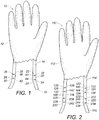
- Figures 1 , 3 and 4 show embodiments of the connection portion 18 with the glove 10 in the relaxed position, a first locked position, and a second locked position, respectively.
- the cuff portion 16 and the sleeve portion 14 are in alignment, and there is no barrier to liquid flow down the glove 10.
- the relaxed position facilitates putting on the glove 10 and taking off the glove 10.
- the connection portion 18 comprises an annular ridge 26.
- the annular ridge 26 has a surface 20, a first V-shaped channel 22 on a first side 28 of the surface 20, and a second V-shaped channel 24 on a second side 30 of the surface 20.
- the surface 20 is generally parallel to the sleeve portion 14.
- the surface 20 can be flat.
- the thickness of the annular ridge 26 at the surface 20 can be the same as the thickness of the sleeve portion 14, the cuff portion 16 or both.
- the surface 20 can appear "raised” because the thickness is greater than the thickness of either of the V-shaped channels 22, 24.
- the surface 20 is not necessarily greater in thickness than either the sleeve portion 14, the cuff portion 16 or both.
- FIGS. 1 , 3 and 4 show the annular ridge 26 having a partial cross-section formed by a first side wall 32, the surface 20, and the second side wall 34.
- the partial cross-section can be generally rectangular with sharp edges formed at both the first side 28 and second side 30 of the surface 20.
- the first side wall 32 is generally orthogonal to the surface 20 and forms a sharp edge on the first side 28.
- the sharp edge can be a type of square edge.
- the second side wall 34 can also be generally orthogonal to the surface 20 on an opposite side, the second side 30, of the surface 20, forming another sharp edge.
- the first V-shaped channel 22 forms a first crease 38 adjacent the sleeve portion 14, and the second V-shaped channel 24 forms a second crease 42 adjacent the cuff portion 16.
- the creases 38, 42 form the pivot for the cuff portion 16 to fold over the sleeve portion 14.
- the creases 38, 42 predetermine the location of the pivot.
- the creases 38, 42 are well defined pivots so there is no ambiguity about which portion of the glove 10 is best able to fold.
- the present invention pre-determines the possible folds.
- the creases 38, 42 are the most structurally obvious points for folding.
- the creases 38, 42 cinch the adjacent portion to the annular ridge 26.
- the first crease 38 is continuous with the adjacent sleeve portion 14 and clinches the sleeve portion 14 to the crease 38.
- the second crease 42 is continuous with the adjacent cuff portion 16 and cinches the cuff portion 16 to the annular ridge 26.
- the overall shape of the glove is conical, so the diameters are increases from the wrist of the hand portion 12 to the cuff portion 16.
- the first crease 38 has a first diameter smaller than the sleeve portion 14, and the second crease 42 has a second diameter smaller than the cuff portion 16. The smaller diameters cause the cinching relationship between the portions adjacent the connection portion 18.
- the first V-shaped channel 22 has a first bottom end 40 with a thickness less than the sleeve portion 14.
- the second V-shaped channel 24 can have a second bottom end 44 with a thickness less than the cuff portion 16.
- These bottom ends 40, 44 are located at the deepest point of the V-shape, respectively.
- These bottom ends 40, 44 are portions of the glove 10 with the smallest thickness, which also define the pivots for folding. The point with the smallest thickness can also define the pivot for the folds.
- the bottom ends 40, 44 form the pivot point analogous to the creases 38, 42.
- the smaller diameters of the bottom ends 40, 44 cinch the adjacent portion, forming a distinct pivot.
- Another alternative embodiment includes a plurality of pin holes (not shown) on the connection portion 18.
- the pin holes are placed in the bottom ends 40, 44 of the V-shaped channels 22, 24 or along the creases 38, 42.
- the pin holes weaken the layer of material so that the material is more flexible at the pivot. Pin holes further reinforce the set position of the fold without weakening an entire portion as in the prior art.
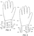
- Figures 3-4 show the locked positions of the glove 10 with a cuff formed by the cuff portion 16.
- Figure 3 shows the first locked position with the first V-shaped channel 22 collapsed so as to fold the cuff portion 16 over the sleeve portion 14.
- the sleeve portion 14 faces the surface 20.
- Figure 4 shows the second locked position with the second V-shaped channel 24 collapsed so as to fold the cuff portion 16 over the sleeve portion 14 with the cuff portion 16 facing the surface 20.
- Figures 3 and 4 show an embodiment with one annular ridge 26. There are two distinct folds to hold the cuff portion 16 over the sleeve portion 14.
- Either fold can hold, so that the user is able to pull the cuff portion 16 to either locked position. Wear on the V-shaped channels 22, 24 can reduce strength of the locked position, so the remaining channel 22, 24 can still be an alternative to the worn channel.
- the present invention can have a longer working life as a glove with a locked cuff.
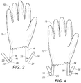
- FIGs 2 , 5 and 6 show the connection portion 118 with an annular ridge 126, a rim portion 146 and an additional annular ridge 226.
- the annular ridge 126 comprises a surface 120, a first V-shaped channel 122 on a first side 128 of the surface 120, and a second V-shaped channel 124 on a second side 130 of the surface 120. Structures of the annular ridge 126 are directly analogous to the annular ridge 26 of the embodiment of Figures 1 , 3 and 4 .
- the annular ridge 126 has a partial cross-section formed by a first side wall 132, the surface 120, and the second side wall 134.
- the partial cross-section can be generally rectangular with sharp edges formed at both the first side 128 and second side 130 of the surface 120 by the first side wall 132 and the second side wall 134 being generally orthogonal to the surface 120.
- the first V-shaped channel 122 forms a first crease 138 adjacent the sleeve portion 114.
- the second V-shaped channel 124 forms a second crease 142 adjacent the rim portion 146.
- the first V-shaped channel 122 can have a first bottom end 140 with a thickness less than the sleeve portion 114
- the second V-shaped channel 124 can have a second bottom end 144 with a thickness less than the rim portion 146.
- Analogous folds at the V-shaped channels 122, 124 set the pivot of the cuff portion 116 over the sleeve portion 114.
- Embodiments in Figures 2 , 5 and 6 add the additional annular ridge 226.
- the additional annular ridge 226 comprises an additional surface 220, an additional first V-shaped channel 222 on an additional first side 228 of the additional surface 220, and an additional second V-shaped channel 224 on an additional second side 130 of the additional surface 220. Structures of the additional annular ridge 226 are directly analogous to the annular ridge 126.
- the additional annular ridge 226 has a partial cross-section formed by an additional first side wall 232, the additional surface 220, and the additional second side wall 234.
- the partial cross-section can be generally rectangular with sharp edges formed at both the additional first side 228 and additional second side 230 of the additional surface 220 by the additional first side wall 232 and the additional second side wall 234 being generally orthogonal to the additional surface 220.
- the additional first V-shaped channel 222 forms an additional first crease 238 adjacent the rim portion 146
- the additional second V-shaped channel 224 forms an additional second crease 242 adjacent the cuff portion 116
- the additional first V-shaped channel 222 can have an additional first bottom end 240 with a thickness less than the sleeve portion 114
- the additional second V-shaped channel 224 can have an additional second bottom end 244 with a thickness less than the rim portion 146.
- Analogous folds at the additional V-shaped channels 222, 224 set the pivot of the cuff portion 116 over the sleeve portion 114.
- all creases 138, 142, 238, 242 cinch the respective adjacent portions to the annular ridges 126, 226.
- the first crease 138 is continuous with the adjacent connection portion 118 and sleeve portion 114 and clinches the connection portion 118 to the crease 138.
- the second crease 142 is continuous with the adjacent cuff portion 116 and cinches the cuff portion 116 to the annular ridge 126.
- the additional first crease 238 and additional second crease 242 are continuous with the respective adjacent sleeve portion 114 to clinch the sleeve portion 114 to the crease 238 and continuous with the respective adjacent connection portion 118 to clinch the connection portion 118 to the annular ridge 226.
- the overall shape of the glove remains conical, so the diameters are increasing from the wrist of the hand portion 112 to the cuff portion 116.
- the first crease 138 has a first diameter smaller than the adjacent connection portion 118
- the second crease 142 has a second diameter smaller than the cuff portion 116
- the additional first crease 238 has an additional first diameter smaller than the adjacent sleeve portion 116
- the additional second crease 242 has an additional second diameter smaller than the connection portion 118.
- the smaller diameters cause the cinching relationship between the portions adjacent the connection portion 118.
- the rim portion 146 is generally frustoconical, extending from the annular ridge 126 and the sleeve portion 114 to the additional annular ridge 226 and the cuff portion 116.
- the rim portion 146 can have a thickness analogous to the sleeve portion 114, the cuff portion 116 or both. Variations may include the rim portion 146 having a different thickness, such as thinner or thicker than the sleeve portion 114.
- the surface 120 and the additional surface 220 are generally parallel to the sleeve portion 114.
- the rim portion 146 extends conically outward from the annular ridge 126 to the additional annular ridge 226.
- the annular ridge 126 connects to the sleeve portion 114, and the additional annular ridge 226 connects to the cuff portion 116.
- the creases 138, 142, 238, 242 are now all well defined pivots so there is no ambiguity about which portion of the glove 110 is best able to fold.
- the present invention pre-determines the possible folds at these four options.
- the creases 138, 142, 238, 242 become the most structurally obvious points for folding.
- the first bottom end 140, the second bottom end 144, the additional first bottom end 240, and the additional second bottom end 244 have thicknesses less than the respective sleeve portion 114, rim portion 146, or cuff portion 116.
- bottom ends 140, 144, 240, 244 at the deepest point of the V-shape respectively also define pivots for folding, as the smallest thicknesses of the glove 110.
- the V-shaped channels 122, 124, 222, and 224 form the respective pivot points for different folds of the cuff portion 116 over the sleeve portion 114.
- the channels 122, 124, 222, and 224 are formed by pre-cut slots in the mold of the glove 110. The flaring of the cuff portion 116 maintains the fold of the cuff portion 116.
- Figures 5-6 show various embodiments of the additional locked positions of the glove 110 with a cuff formed by the cuff portion 116.
- the locked positions are not shown in Figures 5 and 6 .
- These locked positions are directly analogous to Figures 3 and 4 with folds on both sides of annular ridge 26. Folds at annular ridge 126 are possible in the embodiments of Figures 5 and 6 , but not shown.
- Figure 5 shows the additional first locked position with the first V-shaped channel 222 collapsed so as to fold the cuff portion 116 over the rim portion 146 and sleeve portion 114.
- the rim portion 146 faces the additional surface 220.
- Figure 6 shows the additional second locked position with the second V-shaped channel 224 collapsed so as to fold the cuff portion 116 over the rim portion 146 and the sleeve portion 114 with the cuff portion 116 facing the additional surface 220.
- Figures 5 and 6 show an embodiment with one annular ridge 126 and an additional annular ridge 226. There are four distinct folds to hold the cuff portion 116 over the sleeve portion 114. The user is able to pull the cuff portion 116 to any of four locked positions. Wear on channels 122, 124, 222, 224 is further distributed across four pivots for an even longer working life as a glove with a locked cuff.
- Embodiments of the present invention include the method of assembling the glove.
- the method includes forming a mold with a hand section, a sleeve section made integral with the hand section, a cuff section, and a connection section between the sleeve section and the cuff section.
- the method also includes dipping the mold into a glove composition in liquid form from the hand section to the cuff section and then removing the mold from the glove composition so as to allow excess glove composition to drip from the mold.
- the glove composition can be rubber or latex or similar material composition.
- the glove composition flows from the cuff section across the connection portion, across the sleeve section, and along the hand section so as to drip from the hand section.
- the glove composition is cured on the mold so as to form a layer. Then, the layer is removed from the mold by folding the layer inside out, the layer corresponding to the hand section forming the hand portion, the layer corresponding to the sleeve section forming the sleeve portion, the layer corresponding to the cuff section forming the cuff portion, the layer corresponding to the connection section forming the connection portion.
- connection section is comprised of a groove between the sleeve section and the cuff section, the groove having squared edges and an inset diameter smaller than the cuff section, at least one squared edge being made integral with the cuff section.
- the glove composition fills the groove and flows over the groove from the cuff section to the sleeve section after the groove is filled.
- the layer corresponding to the groove forms the annular ridge having the surface with the first V-shaped channel on the first side and the second V-shaped channel on the second side, the squared edges corresponding to the V-shaped channels.
- the annular ridge has a partial cross-section formed by a first side wall, the surface, and a second side wall.
- the partial cross-section is generally rectangular, corresponding to the shape of the groove on the mold.
- the surface can correspond to the layer on the inset diameter of the groove.
- the creases correspond to the layer on the squared edges of the groove.
- the creases cinching the connection portion.
- the first crease has a first diameter smaller than the connection portion, and the second crease has a second diameter smaller than the cuff portion.
- the first crease remains continuous and integral with the connection portion
- the second crease remains continuous and integral with the cuff portion.
- the method also includes forming a glove with the connection section further comprised of an additional groove between the sleeve section and the cuff section.
- the additional groove has additional squared edges and an additional inset diameter smaller than the sleeve section, at least one additional squared edge being made integral with the sleeve section.
- the additional groove is adjacent the sleeve portion, and the groove is adjacent the cuff portion.
- the additional groove and the groove are placed on opposite sides of the connection portion. The dipping, the dripping and flowing are all in line with the sequence of the hand section, sleeve section, additional groove, groove, and the cuff section.
- the additional groove is similarly filled and flowed over in this order relative to the other parts of the mold.
- the additional V-shaped channels and creases enable additional cinching at the additional locations at the additional channels and creases.
- the additional locking positions on the glove are now formed with the connection section with more than one groove.
- Embodiments of the present invention provide a glove with a cuff. There is a relaxed position to facilitate wearing the glove and removing the glove. There are different embodiments of locked positions of the glove, wherein the cuff portion is folded over the sleeve portion to form a barrier at the connection portion. Depending upon how much and how hard the user pulls the cuff portion, a different locked position can be engaged. Each locked position sets a cuff by the cuff portion. There can be variations in size of the cuff, depending on how much cuff portion is pulled. The barrier prevents liquid from leaking onto the wearer from the hand portion and sleeve portion of the glove.
- connection portion has an annular ridge with a surface and V-shaped channels on both sides of the surface.
- the sides of the annular ridge cut into the glove to set a pivot of the fold of the glove.
- the bottom end of each V-shaped channel sets a pivot for the fold.
- Either side of the annular ridge can set the pivot at V-shaped channels.
- the round beads or thickened bulges of the prior art cannot achieve the directed and supported fold of the embodiments of the present invention.
- the annular ridge of the connection portion forms an abrupt transition between the smooth sleeve portion and the smooth cuff portion.
- the pivot of a fold is set without the ambiguity of the prior art curvatures and bulges.
- the pivot can be set on either side of the annular ridge. Additionally, pivots can be set by either the annular ridge or the additional annular ridge, when there are two ridges.
- the strongly defined pivot allows the present invention to set and support the fold with creases and flat surfaces.
- the annular ridge can have squared edges defined by the partial cross-section of the first side wall, surface, and the second side wall.
- the orthogonal relationship between the sides and surface form the predetermined pivot for the sleeve portion or the rim portion relative to the rim portion or cuff portion, respectively.
- the difficulty of casting the bulges, uneven thickening, and round beads is completely avoided by the present invention.
- connection portion with the annular ridge, the rim portion and an additional annular ridge.
- the additional annular ridge has the same additional surface and additional V-shaped channels for even more possible pivots. Any user of any size hands and arms can pull the desired amount of cuff portion to lock the cuff portion in place.
- the options for setting and supporting the fold of the cuff portion give flexibility in size and reduce wear on any one V-shaped channel. The working life of cuff, and the overall working life of the glove are extended by the embodiments of the present invention.
Landscapes
- Health & Medical Sciences (AREA)
- Engineering & Computer Science (AREA)
- Surgery (AREA)
- Life Sciences & Earth Sciences (AREA)
- Textile Engineering (AREA)
- Heart & Thoracic Surgery (AREA)
- Biomedical Technology (AREA)
- Medical Informatics (AREA)
- Molecular Biology (AREA)
- Animal Behavior & Ethology (AREA)
- General Health & Medical Sciences (AREA)
- Public Health (AREA)
- Veterinary Medicine (AREA)
- Gloves (AREA)
Claims (20)
- Gant (10, 110) comprenant :une partie de main (12, 112) ;une partie de manchette (14, 114) solidaire de ladite partie de main et s'étendant de manière conique vers l'extérieur à partir de ladite partie de main ;une partie de poignet (16, 116) solidaire avec ladite partie de manchette et s'étendant de manière conique vers l'extérieur à partir de ladite partie de manchette ; etune partie de raccordement (18, 118) entre ladite partie de poignet et ladite partie de manchette, ladite partie de raccordement étant composée d'une crête annulaire (26, 126) sur un côté extérieur de ladite partie de raccordement, ladite partie de poignet se pliant sur ladite partie de manchette au niveau de ladite partie de raccordement, le gant étant caractérisé en ce que :
ladite crête annulaire est composée d'une surface avec un premier canal en forme de V (22, 122) sur un premier côté de ladite surface et un second canal en forme de V (24, 124) sur un second côté de ladite surface. - Gant selon la revendication 1, dans lequel ladite crête annulaire a une section transversale partielle formée par une première paroi latérale, ladite surface et une seconde paroi latérale, ladite section transversale partielle étant généralement rectangulaire.
- Gant selon la revendication 2, dans lequel ladite première paroi latérale est généralement orthogonale à ladite surface, et dans lequel ladite seconde paroi latérale est généralement orthogonale à ladite surface sur un côté opposé de ladite surface.
- Gant selon la revendication 1, dans lequel ladite première paroi latérale forme un premier pli adjacent à ladite partie de manchette afin d'attacher ladite partie de raccordement audit premier pli.
- Gant selon la revendication 4, dans lequel ladite seconde paroi latérale forme un second pli adjacent à ladite partie de poignet afin d'attacher ladite partie de poignet audit second pli, et
dans lequel ledit premier pli a un premier diamètre inférieur à ladite partie de raccordement, ledit second pli ayant un second diamètre inférieur à ladite partie de poignet, ledit premier pli étant continu avec ladite partie de raccordement, ledit second pli étant continu avec ladite partie de poignet. - Gant selon la revendication 1, dans lequel ledit premier canal en forme de V a une première extrémité inférieure avec une épaisseur inférieure à ladite partie de manchette.
- Gant selon la revendication 6, dans lequel ledit second canal en forme de V a une seconde extrémité inférieure avec une épaisseur inférieure à ladite partie de poignet.
- Gant selon la revendication 1, dans lequel ladite partie de raccordement est composée d'une pluralité de trous d'épingle, lesdits trous d'épingle étant recouverts par ladite partie de poignet lorsque ladite partie de poignet se replie sur ladite partie de manchette.
- Gant selon la revendication 1, dans lequel ladite partie de poignet a une position détendue avec ladite surface généralement parallèle à la partie de manchette,
dans lequel ladite partie de poignet a une première position verrouillée avec le premier canal en forme de V affaissé, ladite partie de poignet se repliant sur ladite partie de manchette, ladite partie de manchette faisant face à ladite surface, et
dans lequel ladite partie de poignet a une deuxième position verrouillée avec le second canal en forme de V affaissé, ladite partie de poignet se repliant sur ladite partie de manchette, ladite partie de poignet faisant face à ladite surface. - Gant selon la revendication 1, dans lequel ladite partie de raccordement comprend en outre :une crête annulaire supplémentaire ; etune partie de bord entre ladite crête annulaire et ladite crête annulaire supplémentaire, ladite partie de bord s'étendant de manière conique vers l'extérieur à partir de ladite crête annulaire jusqu'à ladite crête annulaire supplémentaire,dans lequel ladite crête annulaire se raccorde à ladite partie de manchette, dans lequel ladite crête annulaire supplémentaire se raccorde à ladite partie de poignet, etdans lequel ladite crête annulaire supplémentaire a une surface supplémentaire, un premier canal en forme de V supplémentaire sur un premier côté supplémentaire, et un second canal en forme de V supplémentaire sur un second côté supplémentaire de ladite surface supplémentaire.
- Gant selon la revendication 10, dans lequel ladite crête annulaire a une section transversale partielle formée par une première paroi latérale, ladite surface et une seconde paroi latérale, ladite section transversale partielle étant généralement rectangulaire, et
dans lequel ladite crête annulaire supplémentaire a une section transversale partielle formée par ladite première paroi latérale supplémentaire, ladite surface supplémentaire, et ledit second côté supplémentaire, ladite section transversale partielle étant généralement rectangulaire. - Gant selon la revendication 11, dans lequel ladite première partie latérale est généralement orthogonale à ladite surface,
dans lequel ladite seconde paroi latérale est généralement orthogonale à ladite surface sur un côté opposé de ladite surface,
dans lequel ladite première paroi latérale supplémentaire est généralement orthogonale à ladite surface supplémentaire, et
dans lequel ladite seconde paroi latérale supplémentaire est généralement orthogonale à ladite surface supplémentaire sur un côté opposé de ladite surface supplémentaire. - Gant selon la revendication 10, dans lequel ladite première paroi latérale forme un premier pli adjacent à ladite partie de manchette afin d'attacher ladite partie de raccordement audit premier pli, dans lequel ladite seconde paroi latérale forme un second pli adjacent à ladite partie de bord afin d'attacher ladite partie de bord audit second pli, dans lequel ladite première paroi latérale supplémentaire forme un premier pli supplémentaire adjacent à ladite partie de bord afin d'attacher ladite partie de raccordement audit premier pli supplémentaire, dans lequel ladite seconde paroi latérale supplémentaire forme un second pli supplémentaire adjacent à ladite partie de poignet afin d'attacher ladite partie de poignet audit second pli,
dans lequel ledit premier pli a un premier diamètre inférieur à ladite partie de raccordement, ledit premier pli étant continu avec ladite partie de raccordement,
dans lequel ledit second pli a un second diamètre inférieur à ladite partie de bord, ledit second pli étant continu avec ladite partie de bord,
dans lequel ledit premier pli supplémentaire a un premier diamètre supplémentaire inférieur à ladite partie de bord, ledit premier pli supplémentaire étant continu avec ladite partie de bord, et
dans lequel ledit second pli supplémentaire a un second diamètre supplémentaire inférieur à ladite partie de poignet, ledit second pli supplémentaire étant continu avec ladite partie de poignet. - Gant selon la revendication 10, dans lequel ledit premier canal en forme de V a une première extrémité inférieure avec une épaisseur inférieure à ladite partie de manchette, dans lequel ledit second canal en forme de V a une seconde extrémité inférieure avec une épaisseur inférieure à ladite partie de bord, dans lequel ledit premier canal en forme de V supplémentaire a une première extrémité inférieure supplémentaire avec une épaisseur inférieure à ladite partie de bord, et dans lequel ledit second canal en forme de V supplémentaire a une seconde extrémité inférieure supplémentaire avec une épaisseur inférieure à ladite partie de poignet.
- Gant selon la revendication 10, dans lequel ladite partie de poignet a une position détendue avec ladite surface et ladite surface supplémentaire généralement parallèles à ladite partie de manchette,
dans lequel ladite partie de poignet a une première position verrouillée avec ledit premier canal en forme de V affaissé, ladite partie de poignet et ladite partie de bord se repliant sur ladite partie de manchette, ladite partie de manchette faisant face à ladite surface,
dans lequel ladite partie de poignet a une deuxième position verrouillée avec le second canal en forme de V affaissé, ladite partie de poignet et ladite partie de bord se repliant sur ladite partie de manchette, ladite partie de bord faisant face à ladite surface,
dans lequel ladite partie de poignet a une troisième position verrouillée avec le premier canal en forme de V supplémentaire affaissé, ladite partie de poignet se repliant sur ladite partie de bord et ladite partie de manchette, ladite partie de bord faisant face à la surface plate supplémentaire, et
dans lequel ladite partie de poignet a une quatrième position verrouillée avec le second canal en forme de V supplémentaire affaissé, ladite partie de poignet se repliant sur ladite partie de bord et ladite partie de manchette, ladite partie de poignet faisant face à ladite surface plate supplémentaire. - Procédé pour assembler le gant (10, 110) selon la revendication 1, ledit procédé comprenant les étapes consistant à :former un moule avec une section de main, une section de manchette solidaire avec ladite section de main, une section de poignet et une section de raccordement entre ladite section de manchette et ladite section de poignet, ladite section de raccordement étant composée d'une rainure entre ladite section de manchette et ladite section de poignet, ladite rainure ayant des bords carrés et un diamètre d'insert inférieur à ladite section de poignet, au moins un bord carré étant solidaire de ladite section de poignet ;tremper ledit moule dans une composition de gant sous forme liquide de ladite section de main à ladite section de poignet ;retirer ledit moule de ladite composition de gant afin de permettre à la composition de gant en excès de s'égoutter dudit moule ;laisser s'écouler la composition de gant (10, 110) à partir de ladite section de poignet (16, 116) de part et d'autre de ladite partie de raccordement (18, 118), de part et d'autre de ladite section de manchette (14, 114) ; et le long de ladite section de main (12, 112) afin de s'égoutter de ladite section de main, dans lequel la composition de gant remplit ladite rainure, et dans lequel ladite composition de gant s'écoule sur ladite rainure, de ladite section de poignet à ladite section de manchette après le remplissage de ladite rainure ;faire durcir ladite composition de gant sur ledit moule après que l'arrêt de l'égouttage afin de former une couche ; etretirer ladite couche dudit moule en retournant ladite couche, ladite couche correspondant à ladite section de main formant ladite partie de main, ladite couche correspondant à ladite section de manchette formant ladite partie de manchette, ladite couche correspondant à ladite section de poignet formant ladite partie de poignet, ladite couche correspondant à ladite section de raccordement formant ladite partie de raccordement,dans lequel ladite couche correspondant à ladite rainure forme ladite crête annulaire (26, 126) sur un côté extérieur de ladite partie de raccordement ayant ladite surface avec ledit premier canal en forme de V (22, 122) sur ledit premier côté de ladite surface et ledit second canal en forme de V (24, 124) sur ledit second côté de ladite surface, lesdits bords carrés correspondant aux canaux en forme de V.
- Procédé pour assembler le gant selon la revendication 16, dans lequel ladite crête annulaire a une section transversale partielle formée par une première paroi latérale, ladite surface et une seconde paroi latérale, ladite section transversale partielle étant généralement rectangulaire, ladite surface correspondant à ladite couche sur ledit diamètre d'insert de ladite rainure.
- Procédé pour assembler le gant selon la revendication 16, comprenant en outre les étapes consistant à :attacher ladite partie de raccordement à un premier pli, ladite première paroi latérale formant ledit premier pli adjacent à ladite partie de manchette ; etattacher ladite partie de poignet à un second pli, ladite seconde paroi latérale formant ledit second pli adjacent à ladite partie de poignet,dans lequel ledit premier pli a un premier diamètre inférieur à ladite partie de raccordement, ledit second pli ayant un second diamètre inférieur à ladite partie de poignet, ledit premier pli étant continu avec ladite partie de raccordement, ledit second pli étant continu avec ladite partie de poignet.
- Procédé pour assembler le gant selon la revendication 16, dans lequel ladite section de raccordement est en outre composée d'une rainure supplémentaire entre ladite section de manchette et ladite section de poignet, ladite rainure supplémentaire ayant des bords carrés supplémentaires et un diamètre d'insert supplémentaire inférieur à ladite section de manchette, au moins un bord carré supplémentaire étant solidaire avec ladite section de manchette,
dans lequel l'étape consistant à tremper ledit moule dans une composition de gant sous forme liquide de ladite section de main à ladite section de poignet comprend l'étape consistant à tremper ladite section de manchette jusqu'à ladite rainure supplémentaire de ladite section de raccordement, à ladite rainure de ladite section de raccordement et jusqu'à ladite section de poignet,
dans lequel l'étape consistant à laisser s'écouler la composition de gant est en outre composée de l'écoulement de ladite section de poignet de part et d'autre de ladite rainure de ladite partie de raccordement, de part et d'autre de ladite rainure supplémentaire de ladite partie de raccordement, le long de ladite section de manchette, et le long de ladite section de main afin de s'égoutter à partir de ladite section de main, et
dans lequel la composition de gant remplit ladite rainure et ladite rainure supplémentaire, et dans lequel ladite composition de gant s'écoule sur ladite rainure et ladite rainure supplémentaire à partir de ladite section de poignet jusqu'à ladite section de manchette après que ladite rainure et ladite rainure supplémentaire ont été remplies. - Procédé pour assembler le gant selon la revendication 19, dans lequel ladite couche correspondant à ladite rainure supplémentaire forme une crête annulaire supplémentaire ayant une surface supplémentaire avec un premier canal en forme de V supplémentaire sur un premier côté supplémentaire et un second canal en forme de V supplémentaire sur un second côté supplémentaire, lesdits bords carrés correspondant aux canaux en forme de V supplémentaires.
Applications Claiming Priority (3)
| Application Number | Priority Date | Filing Date | Title |
|---|---|---|---|
| US201461975834P | 2014-04-06 | 2014-04-06 | |
| US14/599,471 US9867672B2 (en) | 2014-04-06 | 2015-01-17 | Glove with a cuff |
| PCT/US2016/013758 WO2016115553A1 (fr) | 2015-01-17 | 2016-01-16 | Gant à poignet |
Publications (3)
| Publication Number | Publication Date |
|---|---|
| EP3244761A1 EP3244761A1 (fr) | 2017-11-22 |
| EP3244761A4 EP3244761A4 (fr) | 2018-08-15 |
| EP3244761B1 true EP3244761B1 (fr) | 2021-03-10 |
Family
ID=54208559
Family Applications (1)
| Application Number | Title | Priority Date | Filing Date |
|---|---|---|---|
| EP16738032.8A Not-in-force EP3244761B1 (fr) | 2014-04-06 | 2016-01-16 | Gant à poignet |
Country Status (2)
| Country | Link |
|---|---|
| US (1) | US9867672B2 (fr) |
| EP (1) | EP3244761B1 (fr) |
Families Citing this family (2)
| Publication number | Priority date | Publication date | Assignee | Title |
|---|---|---|---|---|
| US10772474B2 (en) * | 2018-04-27 | 2020-09-15 | David Ganger | Commode wipes |
| US10932506B2 (en) | 2019-02-27 | 2021-03-02 | Core Pacific Llc | Glove with a locked and supported cuff |
Family Cites Families (10)
| Publication number | Priority date | Publication date | Assignee | Title |
|---|---|---|---|---|
| US2106348A (en) * | 1936-12-24 | 1938-01-25 | Surety Rubber Company | Static resisting garment |
| US3099015A (en) * | 1960-06-14 | 1963-07-30 | William J Renehan | Joint for interconnecting tubular members |
| US4756027A (en) * | 1986-05-07 | 1988-07-12 | Buenos Anne M | Cuff constructions |
| GR1002781B (el) | 1996-08-13 | 1997-10-09 | Νεος τυπος γαντιου οικιακης και βιομηχανικης χρησης καθως και φορμας (καλουπιου) για την βιομηχανικη παραγωγη τους. | |
| GR1003416B (el) | 1998-11-19 | 2000-08-31 | Γαντι απο ελαστικο ή αλλο παρεμφερες υλικο | |
| US7480945B2 (en) | 2004-09-22 | 2009-01-27 | Playtex Products, Inc. | Glove having a cuffed portion |
| US7624455B1 (en) * | 2008-06-13 | 2009-12-01 | Jagmohan Bhalla | Sterile glove with touchless donning |
| US7832019B1 (en) * | 2009-12-10 | 2010-11-16 | Jagmohan Bhalla | Sterile glove with touchless donning |
| KR101170362B1 (ko) * | 2012-01-16 | 2012-08-01 | (주) 코멕스라텍스 | 물흐름 방지구조를 갖는 고무장갑 |
| US9113666B2 (en) * | 2012-05-10 | 2015-08-25 | Ashwin George | Easily removable medical gloves |
-
2015
- 2015-01-17 US US14/599,471 patent/US9867672B2/en active Active
-
2016
- 2016-01-16 EP EP16738032.8A patent/EP3244761B1/fr not_active Not-in-force
Non-Patent Citations (1)
| Title |
|---|
| None * |
Also Published As
| Publication number | Publication date |
|---|---|
| EP3244761A1 (fr) | 2017-11-22 |
| US9867672B2 (en) | 2018-01-16 |
| EP3244761A4 (fr) | 2018-08-15 |
| US20150282540A1 (en) | 2015-10-08 |
Similar Documents
| Publication | Publication Date | Title |
|---|---|---|
| US11672289B2 (en) | Glove | |
| US9648912B2 (en) | Sealing device for garments | |
| US7721354B2 (en) | Glove with integrally formed arm trough for capturing liquids and a method therefor | |
| US5953756A (en) | Glove of rubber or the like | |
| EP3244761B1 (fr) | Gant à poignet | |
| EP3167733B1 (fr) | Membrane intermédiaire de gant ayant des fonctions de perméabilité à l'humidité et d'imperméabilité à l'eau et à coupler simultanément à une étoffe extérieure et une doublure intérieure, gants utilisant celle-ci, et procédé de fabrication de celle-ci | |
| CA1208376A (fr) | Raccord de remplissage pour matelas hydrauliques | |
| US10334894B2 (en) | Sealing arrangement for garments | |
| WO2013023685A1 (fr) | Gant | |
| WO2016115553A1 (fr) | Gant à poignet | |
| KR101459570B1 (ko) | 분리 사용이 가능한 고무장갑 | |
| WO2013098551A3 (fr) | Corps de tuyau flexible et procédé | |
| US10932506B2 (en) | Glove with a locked and supported cuff | |
| KR200429669Y1 (ko) | 고무장갑 | |
| KR101489121B1 (ko) | 장갑 및 그 제조방법 | |
| KR100337028B1 (ko) | 고무장갑의 주름형성방법 및 주름형성용 금형 | |
| JP7250361B2 (ja) | グローブ、及びそのグローブを製造する方法 | |
| JP2008285775A (ja) | 液垂れ防止付き手袋 | |
| JP3245254U (ja) | 手袋 | |
| CN206924362U (zh) | 防滑握把套 | |
| EP2896578B1 (fr) | Lumière et bague de retenue de couvercle flexible | |
| US20260084325A1 (en) | Compliant coverings for a robotic hand | |
| CN204561043U (zh) | 一种易戴乳胶手套 | |
| JP3172465U (ja) | 防水手袋 | |
| KR101625355B1 (ko) | 탈착이 간편한 고무장갑 |
Legal Events
| Date | Code | Title | Description |
|---|---|---|---|
| STAA | Information on the status of an ep patent application or granted ep patent |
Free format text: STATUS: THE INTERNATIONAL PUBLICATION HAS BEEN MADE |
|
| PUAI | Public reference made under article 153(3) epc to a published international application that has entered the european phase |
Free format text: ORIGINAL CODE: 0009012 |
|
| STAA | Information on the status of an ep patent application or granted ep patent |
Free format text: STATUS: REQUEST FOR EXAMINATION WAS MADE |
|
| 17P | Request for examination filed |
Effective date: 20170803 |
|
| AK | Designated contracting states |
Kind code of ref document: A1 Designated state(s): AL AT BE BG CH CY CZ DE DK EE ES FI FR GB GR HR HU IE IS IT LI LT LU LV MC MK MT NL NO PL PT RO RS SE SI SK SM TR |
|
| AX | Request for extension of the european patent |
Extension state: BA ME |
|
| DAV | Request for validation of the european patent (deleted) | ||
| DAX | Request for extension of the european patent (deleted) | ||
| A4 | Supplementary search report drawn up and despatched |
Effective date: 20180713 |
|
| RIC1 | Information provided on ipc code assigned before grant |
Ipc: A61B 42/00 20160101ALI20180709BHEP Ipc: A61B 42/50 20160101ALI20180709BHEP Ipc: A41D 19/00 20060101AFI20180709BHEP Ipc: A47L 13/18 20060101ALI20180709BHEP |
|
| GRAP | Despatch of communication of intention to grant a patent |
Free format text: ORIGINAL CODE: EPIDOSNIGR1 |
|
| STAA | Information on the status of an ep patent application or granted ep patent |
Free format text: STATUS: GRANT OF PATENT IS INTENDED |
|
| INTG | Intention to grant announced |
Effective date: 20201001 |
|
| GRAS | Grant fee paid |
Free format text: ORIGINAL CODE: EPIDOSNIGR3 |
|
| GRAA | (expected) grant |
Free format text: ORIGINAL CODE: 0009210 |
|
| STAA | Information on the status of an ep patent application or granted ep patent |
Free format text: STATUS: THE PATENT HAS BEEN GRANTED |
|
| AK | Designated contracting states |
Kind code of ref document: B1 Designated state(s): AL AT BE BG CH CY CZ DE DK EE ES FI FR GB GR HR HU IE IS IT LI LT LU LV MC MK MT NL NO PL PT RO RS SE SI SK SM TR |
|
| REG | Reference to a national code |
Ref country code: GB Ref legal event code: FG4D |
|
| REG | Reference to a national code |
Ref country code: AT Ref legal event code: REF Ref document number: 1368800 Country of ref document: AT Kind code of ref document: T Effective date: 20210315 Ref country code: CH Ref legal event code: EP |
|
| REG | Reference to a national code |
Ref country code: DE Ref legal event code: R096 Ref document number: 602016054004 Country of ref document: DE |
|
| REG | Reference to a national code |
Ref country code: IE Ref legal event code: FG4D |
|
| REG | Reference to a national code |
Ref country code: LT Ref legal event code: MG9D |
|
| PG25 | Lapsed in a contracting state [announced via postgrant information from national office to epo] |
Ref country code: FI Free format text: LAPSE BECAUSE OF FAILURE TO SUBMIT A TRANSLATION OF THE DESCRIPTION OR TO PAY THE FEE WITHIN THE PRESCRIBED TIME-LIMIT Effective date: 20210310 Ref country code: HR Free format text: LAPSE BECAUSE OF FAILURE TO SUBMIT A TRANSLATION OF THE DESCRIPTION OR TO PAY THE FEE WITHIN THE PRESCRIBED TIME-LIMIT Effective date: 20210310 Ref country code: GR Free format text: LAPSE BECAUSE OF FAILURE TO SUBMIT A TRANSLATION OF THE DESCRIPTION OR TO PAY THE FEE WITHIN THE PRESCRIBED TIME-LIMIT Effective date: 20210611 Ref country code: NO Free format text: LAPSE BECAUSE OF FAILURE TO SUBMIT A TRANSLATION OF THE DESCRIPTION OR TO PAY THE FEE WITHIN THE PRESCRIBED TIME-LIMIT Effective date: 20210610 Ref country code: BG Free format text: LAPSE BECAUSE OF FAILURE TO SUBMIT A TRANSLATION OF THE DESCRIPTION OR TO PAY THE FEE WITHIN THE PRESCRIBED TIME-LIMIT Effective date: 20210610 Ref country code: LT Free format text: LAPSE BECAUSE OF FAILURE TO SUBMIT A TRANSLATION OF THE DESCRIPTION OR TO PAY THE FEE WITHIN THE PRESCRIBED TIME-LIMIT Effective date: 20210310 |
|
| REG | Reference to a national code |
Ref country code: AT Ref legal event code: MK05 Ref document number: 1368800 Country of ref document: AT Kind code of ref document: T Effective date: 20210310 |
|
| REG | Reference to a national code |
Ref country code: NL Ref legal event code: MP Effective date: 20210310 |
|
| PG25 | Lapsed in a contracting state [announced via postgrant information from national office to epo] |
Ref country code: SE Free format text: LAPSE BECAUSE OF FAILURE TO SUBMIT A TRANSLATION OF THE DESCRIPTION OR TO PAY THE FEE WITHIN THE PRESCRIBED TIME-LIMIT Effective date: 20210310 Ref country code: RS Free format text: LAPSE BECAUSE OF FAILURE TO SUBMIT A TRANSLATION OF THE DESCRIPTION OR TO PAY THE FEE WITHIN THE PRESCRIBED TIME-LIMIT Effective date: 20210310 Ref country code: LV Free format text: LAPSE BECAUSE OF FAILURE TO SUBMIT A TRANSLATION OF THE DESCRIPTION OR TO PAY THE FEE WITHIN THE PRESCRIBED TIME-LIMIT Effective date: 20210310 |
|
| PG25 | Lapsed in a contracting state [announced via postgrant information from national office to epo] |
Ref country code: NL Free format text: LAPSE BECAUSE OF FAILURE TO SUBMIT A TRANSLATION OF THE DESCRIPTION OR TO PAY THE FEE WITHIN THE PRESCRIBED TIME-LIMIT Effective date: 20210310 |
|
| PG25 | Lapsed in a contracting state [announced via postgrant information from national office to epo] |
Ref country code: EE Free format text: LAPSE BECAUSE OF FAILURE TO SUBMIT A TRANSLATION OF THE DESCRIPTION OR TO PAY THE FEE WITHIN THE PRESCRIBED TIME-LIMIT Effective date: 20210310 Ref country code: CZ Free format text: LAPSE BECAUSE OF FAILURE TO SUBMIT A TRANSLATION OF THE DESCRIPTION OR TO PAY THE FEE WITHIN THE PRESCRIBED TIME-LIMIT Effective date: 20210310 Ref country code: SM Free format text: LAPSE BECAUSE OF FAILURE TO SUBMIT A TRANSLATION OF THE DESCRIPTION OR TO PAY THE FEE WITHIN THE PRESCRIBED TIME-LIMIT Effective date: 20210310 Ref country code: AT Free format text: LAPSE BECAUSE OF FAILURE TO SUBMIT A TRANSLATION OF THE DESCRIPTION OR TO PAY THE FEE WITHIN THE PRESCRIBED TIME-LIMIT Effective date: 20210310 |
|
| PG25 | Lapsed in a contracting state [announced via postgrant information from national office to epo] |
Ref country code: IS Free format text: LAPSE BECAUSE OF FAILURE TO SUBMIT A TRANSLATION OF THE DESCRIPTION OR TO PAY THE FEE WITHIN THE PRESCRIBED TIME-LIMIT Effective date: 20210710 Ref country code: PT Free format text: LAPSE BECAUSE OF FAILURE TO SUBMIT A TRANSLATION OF THE DESCRIPTION OR TO PAY THE FEE WITHIN THE PRESCRIBED TIME-LIMIT Effective date: 20210712 Ref country code: PL Free format text: LAPSE BECAUSE OF FAILURE TO SUBMIT A TRANSLATION OF THE DESCRIPTION OR TO PAY THE FEE WITHIN THE PRESCRIBED TIME-LIMIT Effective date: 20210310 Ref country code: SK Free format text: LAPSE BECAUSE OF FAILURE TO SUBMIT A TRANSLATION OF THE DESCRIPTION OR TO PAY THE FEE WITHIN THE PRESCRIBED TIME-LIMIT Effective date: 20210310 Ref country code: RO Free format text: LAPSE BECAUSE OF FAILURE TO SUBMIT A TRANSLATION OF THE DESCRIPTION OR TO PAY THE FEE WITHIN THE PRESCRIBED TIME-LIMIT Effective date: 20210310 |
|
| REG | Reference to a national code |
Ref country code: DE Ref legal event code: R097 Ref document number: 602016054004 Country of ref document: DE |
|
| PLBE | No opposition filed within time limit |
Free format text: ORIGINAL CODE: 0009261 |
|
| STAA | Information on the status of an ep patent application or granted ep patent |
Free format text: STATUS: NO OPPOSITION FILED WITHIN TIME LIMIT |
|
| PG25 | Lapsed in a contracting state [announced via postgrant information from national office to epo] |
Ref country code: AL Free format text: LAPSE BECAUSE OF FAILURE TO SUBMIT A TRANSLATION OF THE DESCRIPTION OR TO PAY THE FEE WITHIN THE PRESCRIBED TIME-LIMIT Effective date: 20210310 Ref country code: ES Free format text: LAPSE BECAUSE OF FAILURE TO SUBMIT A TRANSLATION OF THE DESCRIPTION OR TO PAY THE FEE WITHIN THE PRESCRIBED TIME-LIMIT Effective date: 20210310 Ref country code: DK Free format text: LAPSE BECAUSE OF FAILURE TO SUBMIT A TRANSLATION OF THE DESCRIPTION OR TO PAY THE FEE WITHIN THE PRESCRIBED TIME-LIMIT Effective date: 20210310 |
|
| 26N | No opposition filed |
Effective date: 20211213 |
|
| PG25 | Lapsed in a contracting state [announced via postgrant information from national office to epo] |
Ref country code: SI Free format text: LAPSE BECAUSE OF FAILURE TO SUBMIT A TRANSLATION OF THE DESCRIPTION OR TO PAY THE FEE WITHIN THE PRESCRIBED TIME-LIMIT Effective date: 20210310 |
|
| PG25 | Lapsed in a contracting state [announced via postgrant information from national office to epo] |
Ref country code: IT Free format text: LAPSE BECAUSE OF FAILURE TO SUBMIT A TRANSLATION OF THE DESCRIPTION OR TO PAY THE FEE WITHIN THE PRESCRIBED TIME-LIMIT Effective date: 20210310 |
|
| PG25 | Lapsed in a contracting state [announced via postgrant information from national office to epo] |
Ref country code: IS Free format text: LAPSE BECAUSE OF FAILURE TO SUBMIT A TRANSLATION OF THE DESCRIPTION OR TO PAY THE FEE WITHIN THE PRESCRIBED TIME-LIMIT Effective date: 20210710 |
|
| REG | Reference to a national code |
Ref country code: DE Ref legal event code: R119 Ref document number: 602016054004 Country of ref document: DE |
|
| PG25 | Lapsed in a contracting state [announced via postgrant information from national office to epo] |
Ref country code: MC Free format text: LAPSE BECAUSE OF FAILURE TO SUBMIT A TRANSLATION OF THE DESCRIPTION OR TO PAY THE FEE WITHIN THE PRESCRIBED TIME-LIMIT Effective date: 20210310 |
|
| REG | Reference to a national code |
Ref country code: CH Ref legal event code: PL |
|
| GBPC | Gb: european patent ceased through non-payment of renewal fee |
Effective date: 20220116 |
|
| REG | Reference to a national code |
Ref country code: BE Ref legal event code: MM Effective date: 20220131 |
|
| PG25 | Lapsed in a contracting state [announced via postgrant information from national office to epo] |
Ref country code: LU Free format text: LAPSE BECAUSE OF NON-PAYMENT OF DUE FEES Effective date: 20220116 Ref country code: GB Free format text: LAPSE BECAUSE OF NON-PAYMENT OF DUE FEES Effective date: 20220116 Ref country code: DE Free format text: LAPSE BECAUSE OF NON-PAYMENT OF DUE FEES Effective date: 20220802 |
|
| PG25 | Lapsed in a contracting state [announced via postgrant information from national office to epo] |
Ref country code: FR Free format text: LAPSE BECAUSE OF NON-PAYMENT OF DUE FEES Effective date: 20220131 Ref country code: BE Free format text: LAPSE BECAUSE OF NON-PAYMENT OF DUE FEES Effective date: 20220131 |
|
| PG25 | Lapsed in a contracting state [announced via postgrant information from national office to epo] |
Ref country code: LI Free format text: LAPSE BECAUSE OF NON-PAYMENT OF DUE FEES Effective date: 20220131 Ref country code: CH Free format text: LAPSE BECAUSE OF NON-PAYMENT OF DUE FEES Effective date: 20220131 |
|
| PG25 | Lapsed in a contracting state [announced via postgrant information from national office to epo] |
Ref country code: IE Free format text: LAPSE BECAUSE OF NON-PAYMENT OF DUE FEES Effective date: 20220116 |
|
| PG25 | Lapsed in a contracting state [announced via postgrant information from national office to epo] |
Ref country code: HU Free format text: LAPSE BECAUSE OF FAILURE TO SUBMIT A TRANSLATION OF THE DESCRIPTION OR TO PAY THE FEE WITHIN THE PRESCRIBED TIME-LIMIT; INVALID AB INITIO Effective date: 20160116 |
|
| PG25 | Lapsed in a contracting state [announced via postgrant information from national office to epo] |
Ref country code: MK Free format text: LAPSE BECAUSE OF FAILURE TO SUBMIT A TRANSLATION OF THE DESCRIPTION OR TO PAY THE FEE WITHIN THE PRESCRIBED TIME-LIMIT Effective date: 20210310 Ref country code: CY Free format text: LAPSE BECAUSE OF FAILURE TO SUBMIT A TRANSLATION OF THE DESCRIPTION OR TO PAY THE FEE WITHIN THE PRESCRIBED TIME-LIMIT Effective date: 20210310 |
|
| PG25 | Lapsed in a contracting state [announced via postgrant information from national office to epo] |
Ref country code: MT Free format text: LAPSE BECAUSE OF FAILURE TO SUBMIT A TRANSLATION OF THE DESCRIPTION OR TO PAY THE FEE WITHIN THE PRESCRIBED TIME-LIMIT Effective date: 20210310 |
|
| PG25 | Lapsed in a contracting state [announced via postgrant information from national office to epo] |
Ref country code: TR Free format text: LAPSE BECAUSE OF FAILURE TO SUBMIT A TRANSLATION OF THE DESCRIPTION OR TO PAY THE FEE WITHIN THE PRESCRIBED TIME-LIMIT Effective date: 20210310 |