EP3244817B1 - Procédé pour la réalisation d'un écartement ou d'une compression des vertèbres dans le cas d'une intervention chirurgicale sur la colonne vertébrale - Google Patents
Procédé pour la réalisation d'un écartement ou d'une compression des vertèbres dans le cas d'une intervention chirurgicale sur la colonne vertébrale Download PDFInfo
- Publication number
- EP3244817B1 EP3244817B1 EP16718343.3A EP16718343A EP3244817B1 EP 3244817 B1 EP3244817 B1 EP 3244817B1 EP 16718343 A EP16718343 A EP 16718343A EP 3244817 B1 EP3244817 B1 EP 3244817B1
- Authority
- EP
- European Patent Office
- Prior art keywords
- bearing part
- longitudinal direction
- extension
- eccentric
- parts
- Prior art date
- Legal status (The legal status is an assumption and is not a legal conclusion. Google has not performed a legal analysis and makes no representation as to the accuracy of the status listed.)
- Active
Links
Images


Classifications
-
- A—HUMAN NECESSITIES
- A61—MEDICAL OR VETERINARY SCIENCE; HYGIENE
- A61B—DIAGNOSIS; SURGERY; IDENTIFICATION
- A61B17/00—Surgical instruments, devices or methods
- A61B17/56—Surgical instruments or methods for treatment of bones or joints; Devices specially adapted therefor
- A61B17/58—Surgical instruments or methods for treatment of bones or joints; Devices specially adapted therefor for osteosynthesis, e.g. bone plates, screws or setting implements
- A61B17/68—Internal fixation devices, including fasteners and spinal fixators, even if a part thereof projects from the skin
- A61B17/70—Spinal positioners or stabilisers, e.g. stabilisers comprising fluid filler in an implant
- A61B17/7074—Tools specially adapted for spinal fixation operations other than for bone removal or filler handling
- A61B17/7076—Tools specially adapted for spinal fixation operations other than for bone removal or filler handling for driving, positioning or assembling spinal clamps or bone anchors specially adapted for spinal fixation
- A61B17/7077—Tools specially adapted for spinal fixation operations other than for bone removal or filler handling for driving, positioning or assembling spinal clamps or bone anchors specially adapted for spinal fixation for moving bone anchors attached to vertebrae, thereby displacing the vertebrae
- A61B17/708—Tools specially adapted for spinal fixation operations other than for bone removal or filler handling for driving, positioning or assembling spinal clamps or bone anchors specially adapted for spinal fixation for moving bone anchors attached to vertebrae, thereby displacing the vertebrae with tubular extensions coaxially mounted on the bone anchors
-
- A—HUMAN NECESSITIES
- A61—MEDICAL OR VETERINARY SCIENCE; HYGIENE
- A61B—DIAGNOSIS; SURGERY; IDENTIFICATION
- A61B17/00—Surgical instruments, devices or methods
- A61B17/56—Surgical instruments or methods for treatment of bones or joints; Devices specially adapted therefor
- A61B17/58—Surgical instruments or methods for treatment of bones or joints; Devices specially adapted therefor for osteosynthesis, e.g. bone plates, screws or setting implements
- A61B17/68—Internal fixation devices, including fasteners and spinal fixators, even if a part thereof projects from the skin
- A61B17/70—Spinal positioners or stabilisers, e.g. stabilisers comprising fluid filler in an implant
- A61B17/7074—Tools specially adapted for spinal fixation operations other than for bone removal or filler handling
- A61B17/7076—Tools specially adapted for spinal fixation operations other than for bone removal or filler handling for driving, positioning or assembling spinal clamps or bone anchors specially adapted for spinal fixation
-
- A—HUMAN NECESSITIES
- A61—MEDICAL OR VETERINARY SCIENCE; HYGIENE
- A61B—DIAGNOSIS; SURGERY; IDENTIFICATION
- A61B17/00—Surgical instruments, devices or methods
- A61B17/56—Surgical instruments or methods for treatment of bones or joints; Devices specially adapted therefor
- A61B17/58—Surgical instruments or methods for treatment of bones or joints; Devices specially adapted therefor for osteosynthesis, e.g. bone plates, screws or setting implements
- A61B17/68—Internal fixation devices, including fasteners and spinal fixators, even if a part thereof projects from the skin
- A61B17/70—Spinal positioners or stabilisers, e.g. stabilisers comprising fluid filler in an implant
- A61B17/7074—Tools specially adapted for spinal fixation operations other than for bone removal or filler handling
- A61B17/7076—Tools specially adapted for spinal fixation operations other than for bone removal or filler handling for driving, positioning or assembling spinal clamps or bone anchors specially adapted for spinal fixation
- A61B17/7077—Tools specially adapted for spinal fixation operations other than for bone removal or filler handling for driving, positioning or assembling spinal clamps or bone anchors specially adapted for spinal fixation for moving bone anchors attached to vertebrae, thereby displacing the vertebrae
-
- A—HUMAN NECESSITIES
- A61—MEDICAL OR VETERINARY SCIENCE; HYGIENE
- A61B—DIAGNOSIS; SURGERY; IDENTIFICATION
- A61B17/00—Surgical instruments, devices or methods
- A61B17/56—Surgical instruments or methods for treatment of bones or joints; Devices specially adapted therefor
- A61B17/58—Surgical instruments or methods for treatment of bones or joints; Devices specially adapted therefor for osteosynthesis, e.g. bone plates, screws or setting implements
- A61B17/68—Internal fixation devices, including fasteners and spinal fixators, even if a part thereof projects from the skin
- A61B17/70—Spinal positioners or stabilisers, e.g. stabilisers comprising fluid filler in an implant
- A61B17/7074—Tools specially adapted for spinal fixation operations other than for bone removal or filler handling
- A61B17/7076—Tools specially adapted for spinal fixation operations other than for bone removal or filler handling for driving, positioning or assembling spinal clamps or bone anchors specially adapted for spinal fixation
- A61B17/7077—Tools specially adapted for spinal fixation operations other than for bone removal or filler handling for driving, positioning or assembling spinal clamps or bone anchors specially adapted for spinal fixation for moving bone anchors attached to vertebrae, thereby displacing the vertebrae
- A61B17/7079—Tools requiring anchors to be already mounted on an implanted longitudinal or transverse element, e.g. where said element guides the anchor motion
-
- A—HUMAN NECESSITIES
- A61—MEDICAL OR VETERINARY SCIENCE; HYGIENE
- A61B—DIAGNOSIS; SURGERY; IDENTIFICATION
- A61B17/00—Surgical instruments, devices or methods
- A61B17/56—Surgical instruments or methods for treatment of bones or joints; Devices specially adapted therefor
- A61B17/58—Surgical instruments or methods for treatment of bones or joints; Devices specially adapted therefor for osteosynthesis, e.g. bone plates, screws or setting implements
- A61B17/68—Internal fixation devices, including fasteners and spinal fixators, even if a part thereof projects from the skin
- A61B17/70—Spinal positioners or stabilisers, e.g. stabilisers comprising fluid filler in an implant
- A61B17/7001—Screws or hooks combined with longitudinal elements which do not contact vertebrae
- A61B17/7002—Longitudinal elements, e.g. rods
Definitions
- the invention relates to a device for performing a distraction or a compression of vertebral bodies in a, in particular minimally invasive, spine surgery, with a first and a second, in particular at least partially sleeve-shaped, extension part with a respective longitudinal direction, which in each case releasably but rigidly to a bone anchor rotatably fixed, wherein the bone anchors are each introduced into one of the vertebral bodies to be treated or already introduced.
- a device of the type mentioned is known.
- a displaceable in the longitudinal direction bearing part is provided in one of the sleeve-shaped extension parts, against which the other sleeve-shaped extension part for forming a bearing point can be applied.
- the displaceable bearing part can be enlarged by clipping on an attachment.
- US 2014/0277151 A1 also discloses a device of the type mentioned above with a cap-shaped, attachable to one of the sleeve-shaped extension parts and optionally displaceable in the longitudinal direction relative to the sleeve-shaped extension part bearing part, which has U-shaped or wing-shaped projections or arms which extend in the transverse direction to the outside and against which the other sleeve-shaped extension part can be applied to form a pivot bearing point.
- U-shaped or wing-shaped projections or arms which extend in the transverse direction to the outside and against which the other sleeve-shaped extension part can be applied to form a pivot bearing point.
- To adapt different transverse distances of the sleeve-shaped extension parts different bearing parts of different transverse extent are used or a bearing part, in which an arm is designed to be adjustable in length in the transverse direction, wherein a rack-like locking mechanism can be used.
- the present invention seeks to provide a device of the type mentioned, which is less complex than prior art devices that is easy to use and economical to produce.
- a device of the type mentioned which is characterized by a first eccentric bearing part and a second abutment member, which are positionable or positioned on corresponding position in the longitudinal direction of the first and on the second extension part, wherein the first eccentric bearing part is an additional to the first extension part movable member and the second abutment part is an additional to the second extension part movable member or formed by the second extension part itself, and in that at least the eccentric bearing part is rotatable relative to the first extension part about its longitudinal direction , so that due to the eccentricity, the first bearing part is brought into abutment with the second abutment part and thereby a bearing point for forming a pivot joint between the two extension parts for carrying out the distraction or Kompre ssion is formed.
- first eccentric bearing part and a second abutment part are provided, in particular both on the extension parts are preferably plugged or pushed, the first eccentric bearing part can be brought by a simple rotation relative to the respective extension part in a touching contact with the abutment member in the other extension part.
- a bearing point for forming a pivot joint between the two extension parts for carrying out the distraction or compression is thereby formed according to the invention.
- the second abutment part could also be formed by the second extension part itself, for example by a counter bearing on the outer surface is formed there, against which the first eccentric bearing part can be supported.
- the eccentric bearing part is further configured such that an enveloping curve tangent to the bearing part has in a circumferential direction a steadily increasing radius or distance from the rotation axis, at least along a part of the outer circumference which is intended to form a bearing point with the abutment part and without having extended arms or the like extensions in the radial direction.
- first eccentric bearing part and / or the second abutment part can be positioned in the longitudinal direction of the respective extension part at a variable position in the longitudinal direction are, that are variably adjustable in the respective longitudinal direction at the respective extension part.
- the pivot point or hinge point in the longitudinal direction can be variably selected according to the circumstances. It is only to be considered that both bearing parts are positioned at a corresponding height or position in the longitudinal direction of the extension parts so that they can cooperate with each other to form the bearing point. This is then selected by the surgeon during surgery according to the specific circumstances.
- a plurality of abutment points in the longitudinal direction could also proceed successively on the second extension part in order to cooperate with the first eccentric bearing part which can be variably positioned in the longitudinal direction.
- the bearing point is stabilized both in the longitudinal direction and in the circumferential direction by such positively locking means to safely support the two against each other to be pivoted extension parts against each other and to guide the distraction or compression movement safely.
- the mentioned positively locking means could be realized in many ways, in particular by additional engagement means and securing means in the form of splints, pins or the like.
- additional engagement means and securing means in the form of splints, pins or the like.
- Such a design simplifies the operation and reduces the complexity of the device.
- first eccentric bearing part or the second abutment part extending in the circumferential direction and in particular concentric to the longitudinal direction radially outwardly open groove and the respective other bearing part radially outwardly projecting area for engagement in the Groove has.
- the width of the groove is preferably greater than the corresponding configuration of the projecting portion for engagement in the groove, and / or there is in any case no exactly complementary formation between the groove and the projecting portion for engagement in the groove, thus engagement and the Training a bearing is also possible if the two extension parts do not run in a plane but in particular "skewed" to each other.
- the groove is formed at the second abutment part and preferably extends concentrically to the longitudinal direction of the associated extension part.
- the means which positively locking in the longitudinal direction and / or in the circumferential direction are formed by the first eccentric bearing part and the second opposing bearing part in the region of the bearing point in the circumferential direction successive locking positions depending on Rotary position of the bearing parts abut each other.
- successively discrete positions of the two bearing parts relative to each other are realized in the circumferential direction.
- detent position is present in the sense of such a discrete investment position of the two parts to each other to understand.
- the means which positively restrains in the longitudinal direction and / or in the circumferential direction thereby are formed, that the first bearing part and the second abutment member abut each other in the region of the bearing over curved or curved surface areas.
- a bearing part in the region of the bearing point could have a groove extending in the circumferential direction with a particular rounded groove base, while a radially outwardly projecting region engaging in this groove has an approximately complementary, in particular saddle-shaped, form on the other bearing part.
- other embodiments are conceivable and possible, with only approximate complementary training is sufficient, as long as an engagement of a bearing part in the other bearing part is made possible to form a position-stabilized bearing point.
- the detent positions or the curved or curved surface areas is formed by a surface design of the two bearing parts and in particular by a surface design of the groove on a bearing part and / or the radially outwardly projecting portion for engagement in the groove on the other bearing part ,
- the first eccentric bearing part or the second abutment part is uniform in the area of contact with the respective other bearing part in the circumferential direction and the other bearing part in the circumferential direction has a varying, but repetitive design. This also makes it possible to realize a self-locking formation of the bearing point, at least in the circumferential direction.
- first eccentric bearing part and / or the second abutment part in the form of a slotted sleeve are formed in particular with a substantially cylindrical inner wall / is. In this way, the bearing parts can be plugged or pushed onto the typically sleeve-shaped extension parts.
- first eccentric bearing part and / or the second abutment part are positionally clamped on the respective extension part is / is.
- Such a clampable positionability can be particularly easily realized that an inner diameter of the respective bearing member is chosen slightly smaller than an outer diameter of the relevant extension part, the bearing member is then still pushed by a slight expansion due to the slot on the relevant extension part.
- the dimensions are then to be selected such that the forces for attaching or pushing the respective bearing part can be easily applied manually, but nevertheless a self-locking clamped fit of the bearing part at the surgeon's intended axial position on the extension part is achieved.
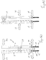
- FIG. 1a shows schematically the conditions in a distraction and FIG. 1b in a compression of vertebral bodies in a spinal surgery.
- Shown schematically is a device according to the invention and designated overall by the reference numeral 2 with a first and a second sleeve portion in an upper region 4 or 6.
- the respective extension part 4, 6 is releasably but rigid and rotationally fixed with an associated bone anchor 8 and 10 connected.
- the bone anchor 8, 10 is by way of example and preferably an osteosynthesis device, the bone anchor 8, 10 each having a threaded shaft 12 for screwing into a vertebral body and a U-shaped in a side view and a receiving opening 14 for a correction element, in particular a correction rod having clevis 16 with two legs 18 includes.
- the respective screw shaft 12 is either rigid, in particular integrally formed with the clevis 16, or it comprises a respective head, which is pivotally mounted within the clevis 16 and permanently fixed in an intended pivotal position with respect to the clevis 16 by the surgeon.
- a so-called polyaxial bone anchor in particular a polyaxial bone screw.
- FIG. 1a Arrows 22 shown above indicate a force introduction or pivotal movement of the two extension parts 4 and 6 with respect to the bearing 20.
- arrows 24 shown below are moved by force and movement of the distal ends of the extension parts 4, 6 on the respective clevis 16 of the bone anchor 8 and 10, the bone anchor 8, 10 and with them the vertebral bodies slightly away from each other, which is referred to as distraction becomes.
- a correspondingly indicated bearing 20 is typically provided in the proximal, ie in the direction away from the bone anchor direction above, and the distal ends of the extension parts 4, 6 are moved towards each other upon application of force according to the arrows 26, which is indicated by the arrows 28. This will cause the bone anchors screwed into the vertebral bodies 8, 10 and thus the vertebral bodies moved towards each other, which is referred to as compression.
- FIG. 2 shows an inventive device 2, comprising two extension parts 4, 6.
- the two extension parts 4, 6 are sleeve-shaped in an upper region and that they each have two distal expiring, against each other slightly resilient clip legs 30 by Of which they are on the legs 18 of the fork head 16 of a bone anchor while releasably, but rigid and rotatably fixed.
- additional parts which come into effect within or outside of the extension parts 4, 6 can be used.
- a rigid sleeve shape with another attachment mechanism to the bone anchor can also be used.
- the device 2 according to the invention further comprises a first eccentric bearing part 40 and a second abutment part 42.
- Both bearing parts 40 and 42 are plugged or pushed onto the respective extension part 4 and 6 respectively. They are relative to the relevant extension part 4, 6 in the respective longitudinal direction 44 and 46 displaced. They are positionable on each other corresponding position in the longitudinal direction 44, 46 and held clamped in this position in the example shown in the example.
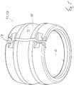
- the first eccentric bearing part 40 and the second abutment part 42 are formed in the illustrated case in the form of a slotted sleeve 48 and 50, respectively.
- a respective slot 52 or 54 is also off FIGS. 3 to 5 seen.
- a respective inner diameter d i of a respective substantially cylindrical inner wall of the bearing parts 40, 42 is in the non-pushed state of Bearing parts geringyoggigst smaller than an outer diameter d a of the extension parts 4, 6.
- the bearing members 40, 42 are expandable and can thus be on the extension parts 4, slide it in the axial direction 44, 46. 6 They are then clamped in a respective position or height on the extension parts 4, 6 held.
- both in the longitudinal direction 44, 46 positively locking means 60 and in the circumferential direction 56 positively locking means 62 are realized by a corresponding design of the outer periphery of the bearing parts 40 and 42.
- the second abutment part 42 comprises a radially outwardly open groove 70 extending in the circumferential direction 56 concentric with the longitudinal direction 42.
- the first eccentric bearing part 40 has a bead-shaped region 72 projecting radially outward and extending in the circumferential direction 56 for engagement with the Groove 70 on.
Landscapes
- Health & Medical Sciences (AREA)
- Neurology (AREA)
- Orthopedic Medicine & Surgery (AREA)
- Life Sciences & Earth Sciences (AREA)
- Surgery (AREA)
- Heart & Thoracic Surgery (AREA)
- Engineering & Computer Science (AREA)
- Biomedical Technology (AREA)
- Nuclear Medicine, Radiotherapy & Molecular Imaging (AREA)
- Medical Informatics (AREA)
- Molecular Biology (AREA)
- Animal Behavior & Ethology (AREA)
- General Health & Medical Sciences (AREA)
- Public Health (AREA)
- Veterinary Medicine (AREA)
- Surgical Instruments (AREA)
Claims (13)
- Dispositif (2) de mise en oeuvre d'une distraction et/ou d'une compression de corps vertébraux dans une intervention chirurgicale sur la colonne vertébrale, en particulier mini-invasive, comprenant une première (4) et une deuxième (6) partie d'allongement qui est en forme de douille, en particulier au moins par sections, et présente une direction longitudinale (44, 46) respective et qui peut être fixée respectivement sur un ancre à os (8, 10), certes, de manière amovible, mais rigide et solidaire en rotation, dans lequel les ancres à os (8, 10) sont à implanter chacun dans un des corps vertébraux à traiter, caractérisé par une première partie de support (40) excentrique et une deuxième contre-partie de support (42) qui peuvent être positionnées ou sont positionnées sur ladite première (4) ou bien ladite deuxième (6) partie d'allongement dans une position correspondant l'une à l'autre dans la direction longitudinale (44, 46), dans lequel la première partie de support (40) excentrique est un composant supplémentaire déplaçable par rapport à la première partie d'allongement (4) et ladite deuxième contre-partie de support (42) est un composant supplémentaire déplaçable par rapport à la deuxième partie d'allongement (6) ou est formée par la deuxième partie d'allongement (6) même, et par le fait qu'au moins la partie de support (40) excentrique peut tourner par rapport à la première partie d'allongement (4) autour de la direction longitudinale (44) de celle-ci de sorte que, en raison de l'excentricité, la première partie de support (40) peut être mise en appui sur la deuxième contre-partie de support (42) et que, ainsi, un point de support (20) est formé pour la réalisation d'une articulation de pivotement entre les deux parties d'allongement (4, 6) afin de mettre en oeuvre la distraction ou la compression.
- Dispositif selon la revendication 1, caractérisé par le fait que la première partie de support (40) excentrique et/ou la deuxième contre-partie de support (42) peuvent être positionnées dans la direction longitudinale (44, 46) de la partie d'allongement (4, 6) respective sur une position variable dans la direction longitudinale (44, 46).
- Dispositif selon la revendication 1 ou 2, caractérisé par le fait que des moyens (60) qui bloquent à engagement positif dans la direction longitudinale (44, 46) sont prévus entre la première partie de support (40) excentrique et la deuxième contre-partie de support (42), ceux-ci stabilisent ledit point de support (20) lorsque la distraction ou la compression est réalisée et empêchent que les parties de support (40, 42) ne s'écartent l'une de l'autre en glissant dans la direction longitudinale (44, 46).
- Dispositif selon la revendication 1, 2 ou 3, caractérisé par le fait que des moyens (62) qui bloquent à engagement positif dans la direction circonférentielle (56) sont prévus entre la première partie de support (40) excentrique et la deuxième contre-partie de support (42), ceux-ci stabilisent ledit point de support (20) lorsque la distraction ou la compression est réalisée et empêchent que les parties de support (40, 42) ne s'écartent l'une de l'autre en glissant dans la direction circonférentielle (56).
- Dispositif selon la revendication 3 ou 4, caractérisé par le fait que lesdits moyens (60) bloquant à engagement positif dans la direction longitudinale (44, 46) qui sont prévus entre la première partie de support (40) excentrique et la deuxième contre-partie de support (42), et/ou lesdits moyens (62) bloquant à engagement positif dans la direction circonférentielle (56) qui sont prévus entre la première partie de support (40) excentrique et la deuxième contre-partie de support (42) sont réalisés uniquement par une conformation de surface de la première partie de support (40) excentrique et de la deuxième contre-partie de support (42), donc sans requérir d'autres éléments.
- Dispositif selon l'une ou plusieurs des revendications précédentes, caractérisé par le fait que la première partie de support (40) excentrique ou la deuxième contre-partie de support (42) présente une rainure (70) ouverte radialement vers l'extérieur qui s'étend dans la direction circonférentielle (56, 58) et, en particulier, est concentrique à la direction longitudinale (44, 46), et l'autre partie de support respective présente une partie (72) faisant radialement saillie vers l'extérieur et destinée à s'engager dans ladite rainure (70).
- Dispositif selon la revendication 3, 4, 5 ou 6, caractérisé par le fait que lesdits moyens (60, 62) bloquant à engagement positif dans la direction longitudinale (44, 46) et/ou dans la direction circonférentielle (56) sont réalisés par le fait que la première partie de support (40) excentrique et la deuxième contre-partie de support (42) s'appliquent l'une contre l'autre au niveau du point de support (20) par des positions d'arrêt (76) successives dans la direction circonférentielle (56), selon la position de rotation des parties de support (40, 42) l'une par rapport à l'autre.
- Dispositif selon la revendication 3, 4, 5, 6 ou 7, caractérisé par le fait que lesdits moyens (60, 62) bloquant à engagement positif dans la direction longitudinale (44, 46) et/ou dans la direction circonférentielle (56) sont réalisés par le fait que la première partie de support (40) et la deuxième contre-partie de support (42) s'appliquent l'une contre l'autre au niveau du point de support (20) par des zones de surface (74) courbées ou bombées.
- Dispositif selon la revendication 7 ou 8, caractérisé par le fait que les positions d'arrêt ou les zones de surface (74) courbées ou bombées sont réalisées par une conformation de surface de la rainure (70) et/ou de la zone (72) faisant saillie radialement vers l'extérieur et destinée à s'engager dans la rainure (70).
- Dispositif selon l'une ou plusieurs des revendications précédentes, caractérisé par le fait que, au niveau de l'appui sur l'autre partie de support respective, la première partie de support (40) excentrique ou la deuxième contre-partie de support (42) est réalisée de manière uniforme dans la direction circonférentielle (56) et l'autre partie de support respective présente une conformation variante, mais se répétant, dans la direction circonférentielle (56).
- Dispositif selon l'une ou plusieurs des revendications précédentes, caractérisé par le fait que la première partie de support (40) excentrique et/ou la deuxième contre-partie de support (42) est/sont réalisée(s) sous la forme d'une douille fendue ayant une paroi intérieure en particulier pour l'essentiel cylindrique.
- Dispositif selon l'une ou plusieurs des revendications précédentes, caractérisé par le fait que la première partie de support (40) excentrique et/ou la deuxième contre-partie de support (42) peut être positionnée par liaison par serrage sur la partie d'allongement respective.
- Dispositif selon l'une ou plusieurs des revendications précédentes, comprenant en outre respectivement un ancre à os (8, 10) pour chaque partie d'allongement (4, 6), dans lequel l'ancre à os (8, 10) comprend une tige (12) ayant une tête ainsi qu'une tête à fourche (16) en U, vue de côté, qui présente un orifice de logement (14) pour un élément de correction, en particulier une barre de correction, et comprend deux branches (18), dans lequel ladite tête de la tige (12) et ladite tête à fourche (16) sont réalisées soit rigidement l'une avec l'autre, en particulier d'un seul tenant, ou la tête de la tige (12) est logée à pivotement à une extrémité distale de la tête à fourche (16) et, dans ce cas, la tête à fourche (16) peut être fixée dans une position de pivotement, envisagée par le chirurgien, par rapport à la tête de la tige (12) fixée ou apte à être fixée dans l'os.
Applications Claiming Priority (2)
| Application Number | Priority Date | Filing Date | Title |
|---|---|---|---|
| DE102015212050.3A DE102015212050B3 (de) | 2015-06-29 | 2015-06-29 | 3Vorrichtung zum Durchführen einer Distraktion oder einer Kompression von Wirbelkörpern bei einer Wirbelsäulenoperation |
| PCT/EP2016/059063 WO2017001080A1 (fr) | 2015-06-29 | 2016-04-22 | Procédé pour la réalisation d'un écartement ou d'une compression des vertèbres dans le cas d'une intervention chirurgicale sur la colonne vertébrale |
Publications (2)
| Publication Number | Publication Date |
|---|---|
| EP3244817A1 EP3244817A1 (fr) | 2017-11-22 |
| EP3244817B1 true EP3244817B1 (fr) | 2018-11-28 |
Family
ID=55808593
Family Applications (1)
| Application Number | Title | Priority Date | Filing Date |
|---|---|---|---|
| EP16718343.3A Active EP3244817B1 (fr) | 2015-06-29 | 2016-04-22 | Procédé pour la réalisation d'un écartement ou d'une compression des vertèbres dans le cas d'une intervention chirurgicale sur la colonne vertébrale |
Country Status (5)
| Country | Link |
|---|---|
| US (1) | US10335208B2 (fr) |
| EP (1) | EP3244817B1 (fr) |
| AU (1) | AU2016287672A1 (fr) |
| DE (1) | DE102015212050B3 (fr) |
| WO (1) | WO2017001080A1 (fr) |
Families Citing this family (3)
| Publication number | Priority date | Publication date | Assignee | Title |
|---|---|---|---|---|
| DE102015212056B3 (de) * | 2015-06-29 | 2016-09-01 | Silony Medical International AG | Vorrichtung zum Durchführen einer Distraktion oder einer Kompression von Wirbelkörpern bei einer Wirbelsäulenoperation |
| DE102017124852A1 (de) * | 2017-10-24 | 2018-10-31 | Silony Medical International AG | Instrument für chirurgische Zwecke |
| ES2871543T3 (es) * | 2018-01-26 | 2021-10-29 | Aesculap Ag | Instrumento de reposicionamiento espinal y sistema de reposicionamiento espinal |
Family Cites Families (10)
| Publication number | Priority date | Publication date | Assignee | Title |
|---|---|---|---|---|
| DE8712943U1 (de) * | 1987-09-25 | 1987-11-12 | Aesculap-Werke Ag Vormals Jetter & Scheerer, 7200 Tuttlingen | Vorrichtung zum Einrichten von Wirbelkörpern |
| US8491590B2 (en) * | 2007-12-05 | 2013-07-23 | Depuy Spine, Inc. | System and method of manipulating spinal constructs |
| KR100942226B1 (ko) * | 2009-09-30 | 2010-02-16 | 주식회사 지에스메디칼 | 로드 홀더 및 이를 이용하는 척추용 최소 침습 수술 시스템 |
| US8491588B2 (en) * | 2011-06-13 | 2013-07-23 | Warsaw Orthopedic, Inc. | Surgical instrument for securing a spinal rod |
| EP2608267B1 (fr) | 2011-12-23 | 2019-02-27 | IHP GmbH-Innovations for High Performance Microelectronics / Leibniz-Institut für innovative Mikroelektronik | Transistor de type p avec une base en graphène |
| US9173687B2 (en) * | 2013-03-15 | 2015-11-03 | DePuy Synthes Products, Inc. | Fulcrum cap for spinal constructs |
| US9622795B2 (en) * | 2013-12-13 | 2017-04-18 | Stryker European Holdings I, Llc | Tissue retraction and vertebral displacement devices, systems, and methods for posterior spinal fusion |
| WO2015200032A1 (fr) * | 2014-06-25 | 2015-12-30 | Spine Wave, Inc. | Fusion postéro-latérale endoscopique |
| US20170020583A1 (en) * | 2015-07-24 | 2017-01-26 | Intai Technology Corporation | Surgery device assembly for minimally invasive spinal surgery |
| US20170311995A1 (en) * | 2016-04-29 | 2017-11-02 | Warsaw Orthopedic, Inc. | Spinal correction system and method |
-
2015
- 2015-06-29 DE DE102015212050.3A patent/DE102015212050B3/de not_active Expired - Fee Related
-
2016
- 2016-04-22 US US15/740,602 patent/US10335208B2/en active Active
- 2016-04-22 AU AU2016287672A patent/AU2016287672A1/en not_active Abandoned
- 2016-04-22 EP EP16718343.3A patent/EP3244817B1/fr active Active
- 2016-04-22 WO PCT/EP2016/059063 patent/WO2017001080A1/fr not_active Ceased
Non-Patent Citations (1)
| Title |
|---|
| None * |
Also Published As
| Publication number | Publication date |
|---|---|
| WO2017001080A1 (fr) | 2017-01-05 |
| DE102015212050B3 (de) | 2016-08-18 |
| AU2016287672A1 (en) | 2018-01-25 |
| US10335208B2 (en) | 2019-07-02 |
| US20180185067A1 (en) | 2018-07-05 |
| EP3244817A1 (fr) | 2017-11-22 |
Similar Documents
| Publication | Publication Date | Title |
|---|---|---|
| EP3117787B1 (fr) | Vis pediculaire avec tulipe | |
| DE102018102173B3 (de) | Polyaxialschraube | |
| EP0537598B1 (fr) | Implant chirurgical de compression | |
| EP3493755B1 (fr) | Vis pédiculaire polyaxiale | |
| DE20320974U1 (de) | Längenverstellbares Wirbelsäulen-Implantat | |
| EP2645950B1 (fr) | Implant pour fusion osseuse destiné aux articulations zygapophysaires | |
| WO1991006254A1 (fr) | Vis pour pedicule vertebral et dispositif de correction et de maintien pourvu d'une telle vis | |
| WO2013189854A1 (fr) | Dispositif de fixation d'un fémur dans le domaine de la pose d'endoprothèses de la hanche | |
| EP0517059A1 (fr) | Crochet pédiculaire | |
| EP1690506B1 (fr) | Dispositif externe de fixation, notamment pour agrandir une distance entre des éléments de serrage | |
| DE102016110706A1 (de) | Spreizer für die Wirbelsäulenchirurgie | |
| WO2017016717A1 (fr) | Dispositif d'ostéosynthèse | |
| EP3244817B1 (fr) | Procédé pour la réalisation d'un écartement ou d'une compression des vertèbres dans le cas d'une intervention chirurgicale sur la colonne vertébrale | |
| EP3534812B1 (fr) | Dispositif pour la réalisation d'une distraction ou d'une compression de corps vertébraux lors d'une chirurgie rachidienne | |
| EP1827272A1 (fr) | Clou centromedullaire | |
| WO2014064253A1 (fr) | Vis à os | |
| DE29614920U1 (de) | Chirurgische Vorrichtung zum Ausrichten und temporären Fixieren eines Kalottensegments | |
| WO2014029032A1 (fr) | Ressort et dispositif de stabilisation d'os humains ou animaux | |
| EP3381376B1 (fr) | Système rétracteur chirurgical doté d'un rétracteur et d'un extracteur | |
| DE102007014730A1 (de) | Manipulator für Rundmaterial, insbesondere für einen Kirschnerdraht | |
| DE10032126B4 (de) | Instrument zum Einführen eines Verbindungsstabes in und durch zueinander ausgerichtete Querbohrungen in den Köpfen von zwei oder mehreren in die Wirbelsäule eingeschraubten Pedikelschrauben | |
| DE102015212056B3 (de) | Vorrichtung zum Durchführen einer Distraktion oder einer Kompression von Wirbelkörpern bei einer Wirbelsäulenoperation | |
| DE102023133177B4 (de) | Medizinisches Set zur Distraktion von Wirbelkörpern | |
| WO2019180048A1 (fr) | Dispositif de libération et de maintien d'ouverture d'un champ opératoire | |
| EP2755581B1 (fr) | Instrument chirurgical à tige tubulaire |
Legal Events
| Date | Code | Title | Description |
|---|---|---|---|
| STAA | Information on the status of an ep patent application or granted ep patent |
Free format text: STATUS: THE INTERNATIONAL PUBLICATION HAS BEEN MADE |
|
| PUAI | Public reference made under article 153(3) epc to a published international application that has entered the european phase |
Free format text: ORIGINAL CODE: 0009012 |
|
| STAA | Information on the status of an ep patent application or granted ep patent |
Free format text: STATUS: REQUEST FOR EXAMINATION WAS MADE |
|
| 17P | Request for examination filed |
Effective date: 20170817 |
|
| AK | Designated contracting states |
Kind code of ref document: A1 Designated state(s): AL AT BE BG CH CY CZ DE DK EE ES FI FR GB GR HR HU IE IS IT LI LT LU LV MC MK MT NL NO PL PT RO RS SE SI SK SM TR |
|
| AX | Request for extension of the european patent |
Extension state: BA ME |
|
| GRAP | Despatch of communication of intention to grant a patent |
Free format text: ORIGINAL CODE: EPIDOSNIGR1 |
|
| STAA | Information on the status of an ep patent application or granted ep patent |
Free format text: STATUS: GRANT OF PATENT IS INTENDED |
|
| DAV | Request for validation of the european patent (deleted) | ||
| DAX | Request for extension of the european patent (deleted) | ||
| INTG | Intention to grant announced |
Effective date: 20180606 |
|
| GRAS | Grant fee paid |
Free format text: ORIGINAL CODE: EPIDOSNIGR3 |
|
| GRAA | (expected) grant |
Free format text: ORIGINAL CODE: 0009210 |
|
| STAA | Information on the status of an ep patent application or granted ep patent |
Free format text: STATUS: THE PATENT HAS BEEN GRANTED |
|
| AK | Designated contracting states |
Kind code of ref document: B1 Designated state(s): AL AT BE BG CH CY CZ DE DK EE ES FI FR GB GR HR HU IE IS IT LI LT LU LV MC MK MT NL NO PL PT RO RS SE SI SK SM TR |
|
| REG | Reference to a national code |
Ref country code: CH Ref legal event code: EP |
|
| REG | Reference to a national code |
Ref country code: AT Ref legal event code: REF Ref document number: 1069314 Country of ref document: AT Kind code of ref document: T Effective date: 20181215 |
|
| REG | Reference to a national code |
Ref country code: DE Ref legal event code: R096 Ref document number: 502016002645 Country of ref document: DE |
|
| REG | Reference to a national code |
Ref country code: IE Ref legal event code: FG4D Free format text: LANGUAGE OF EP DOCUMENT: GERMAN |
|
| REG | Reference to a national code |
Ref country code: NL Ref legal event code: MP Effective date: 20181128 |
|
| REG | Reference to a national code |
Ref country code: LT Ref legal event code: MG4D |
|
| PG25 | Lapsed in a contracting state [announced via postgrant information from national office to epo] |
Ref country code: FI Free format text: LAPSE BECAUSE OF FAILURE TO SUBMIT A TRANSLATION OF THE DESCRIPTION OR TO PAY THE FEE WITHIN THE PRESCRIBED TIME-LIMIT Effective date: 20181128 Ref country code: LV Free format text: LAPSE BECAUSE OF FAILURE TO SUBMIT A TRANSLATION OF THE DESCRIPTION OR TO PAY THE FEE WITHIN THE PRESCRIBED TIME-LIMIT Effective date: 20181128 Ref country code: HR Free format text: LAPSE BECAUSE OF FAILURE TO SUBMIT A TRANSLATION OF THE DESCRIPTION OR TO PAY THE FEE WITHIN THE PRESCRIBED TIME-LIMIT Effective date: 20181128 Ref country code: NO Free format text: LAPSE BECAUSE OF FAILURE TO SUBMIT A TRANSLATION OF THE DESCRIPTION OR TO PAY THE FEE WITHIN THE PRESCRIBED TIME-LIMIT Effective date: 20190228 Ref country code: BG Free format text: LAPSE BECAUSE OF FAILURE TO SUBMIT A TRANSLATION OF THE DESCRIPTION OR TO PAY THE FEE WITHIN THE PRESCRIBED TIME-LIMIT Effective date: 20190228 Ref country code: ES Free format text: LAPSE BECAUSE OF FAILURE TO SUBMIT A TRANSLATION OF THE DESCRIPTION OR TO PAY THE FEE WITHIN THE PRESCRIBED TIME-LIMIT Effective date: 20181128 Ref country code: IS Free format text: LAPSE BECAUSE OF FAILURE TO SUBMIT A TRANSLATION OF THE DESCRIPTION OR TO PAY THE FEE WITHIN THE PRESCRIBED TIME-LIMIT Effective date: 20190328 Ref country code: LT Free format text: LAPSE BECAUSE OF FAILURE TO SUBMIT A TRANSLATION OF THE DESCRIPTION OR TO PAY THE FEE WITHIN THE PRESCRIBED TIME-LIMIT Effective date: 20181128 |
|
| PG25 | Lapsed in a contracting state [announced via postgrant information from national office to epo] |
Ref country code: PT Free format text: LAPSE BECAUSE OF FAILURE TO SUBMIT A TRANSLATION OF THE DESCRIPTION OR TO PAY THE FEE WITHIN THE PRESCRIBED TIME-LIMIT Effective date: 20190328 Ref country code: GR Free format text: LAPSE BECAUSE OF FAILURE TO SUBMIT A TRANSLATION OF THE DESCRIPTION OR TO PAY THE FEE WITHIN THE PRESCRIBED TIME-LIMIT Effective date: 20190301 Ref country code: SE Free format text: LAPSE BECAUSE OF FAILURE TO SUBMIT A TRANSLATION OF THE DESCRIPTION OR TO PAY THE FEE WITHIN THE PRESCRIBED TIME-LIMIT Effective date: 20181128 Ref country code: RS Free format text: LAPSE BECAUSE OF FAILURE TO SUBMIT A TRANSLATION OF THE DESCRIPTION OR TO PAY THE FEE WITHIN THE PRESCRIBED TIME-LIMIT Effective date: 20181128 Ref country code: AL Free format text: LAPSE BECAUSE OF FAILURE TO SUBMIT A TRANSLATION OF THE DESCRIPTION OR TO PAY THE FEE WITHIN THE PRESCRIBED TIME-LIMIT Effective date: 20181128 |
|
| PG25 | Lapsed in a contracting state [announced via postgrant information from national office to epo] |
Ref country code: NL Free format text: LAPSE BECAUSE OF FAILURE TO SUBMIT A TRANSLATION OF THE DESCRIPTION OR TO PAY THE FEE WITHIN THE PRESCRIBED TIME-LIMIT Effective date: 20181128 |
|
| PG25 | Lapsed in a contracting state [announced via postgrant information from national office to epo] |
Ref country code: IT Free format text: LAPSE BECAUSE OF FAILURE TO SUBMIT A TRANSLATION OF THE DESCRIPTION OR TO PAY THE FEE WITHIN THE PRESCRIBED TIME-LIMIT Effective date: 20181128 Ref country code: CZ Free format text: LAPSE BECAUSE OF FAILURE TO SUBMIT A TRANSLATION OF THE DESCRIPTION OR TO PAY THE FEE WITHIN THE PRESCRIBED TIME-LIMIT Effective date: 20181128 Ref country code: DK Free format text: LAPSE BECAUSE OF FAILURE TO SUBMIT A TRANSLATION OF THE DESCRIPTION OR TO PAY THE FEE WITHIN THE PRESCRIBED TIME-LIMIT Effective date: 20181128 Ref country code: PL Free format text: LAPSE BECAUSE OF FAILURE TO SUBMIT A TRANSLATION OF THE DESCRIPTION OR TO PAY THE FEE WITHIN THE PRESCRIBED TIME-LIMIT Effective date: 20181128 |
|
| REG | Reference to a national code |
Ref country code: DE Ref legal event code: R097 Ref document number: 502016002645 Country of ref document: DE |
|
| PG25 | Lapsed in a contracting state [announced via postgrant information from national office to epo] |
Ref country code: SM Free format text: LAPSE BECAUSE OF FAILURE TO SUBMIT A TRANSLATION OF THE DESCRIPTION OR TO PAY THE FEE WITHIN THE PRESCRIBED TIME-LIMIT Effective date: 20181128 Ref country code: EE Free format text: LAPSE BECAUSE OF FAILURE TO SUBMIT A TRANSLATION OF THE DESCRIPTION OR TO PAY THE FEE WITHIN THE PRESCRIBED TIME-LIMIT Effective date: 20181128 Ref country code: RO Free format text: LAPSE BECAUSE OF FAILURE TO SUBMIT A TRANSLATION OF THE DESCRIPTION OR TO PAY THE FEE WITHIN THE PRESCRIBED TIME-LIMIT Effective date: 20181128 Ref country code: SK Free format text: LAPSE BECAUSE OF FAILURE TO SUBMIT A TRANSLATION OF THE DESCRIPTION OR TO PAY THE FEE WITHIN THE PRESCRIBED TIME-LIMIT Effective date: 20181128 |
|
| PLBE | No opposition filed within time limit |
Free format text: ORIGINAL CODE: 0009261 |
|
| STAA | Information on the status of an ep patent application or granted ep patent |
Free format text: STATUS: NO OPPOSITION FILED WITHIN TIME LIMIT |
|
| PG25 | Lapsed in a contracting state [announced via postgrant information from national office to epo] |
Ref country code: SI Free format text: LAPSE BECAUSE OF FAILURE TO SUBMIT A TRANSLATION OF THE DESCRIPTION OR TO PAY THE FEE WITHIN THE PRESCRIBED TIME-LIMIT Effective date: 20181128 |
|
| 26N | No opposition filed |
Effective date: 20190829 |
|
| REG | Reference to a national code |
Ref country code: CH Ref legal event code: PL |
|
| REG | Reference to a national code |
Ref country code: BE Ref legal event code: MM Effective date: 20190430 |
|
| PG25 | Lapsed in a contracting state [announced via postgrant information from national office to epo] |
Ref country code: LU Free format text: LAPSE BECAUSE OF NON-PAYMENT OF DUE FEES Effective date: 20190422 Ref country code: MC Free format text: LAPSE BECAUSE OF FAILURE TO SUBMIT A TRANSLATION OF THE DESCRIPTION OR TO PAY THE FEE WITHIN THE PRESCRIBED TIME-LIMIT Effective date: 20181128 |
|
| PG25 | Lapsed in a contracting state [announced via postgrant information from national office to epo] |
Ref country code: LI Free format text: LAPSE BECAUSE OF NON-PAYMENT OF DUE FEES Effective date: 20190430 Ref country code: CH Free format text: LAPSE BECAUSE OF NON-PAYMENT OF DUE FEES Effective date: 20190430 |
|
| PG25 | Lapsed in a contracting state [announced via postgrant information from national office to epo] |
Ref country code: BE Free format text: LAPSE BECAUSE OF NON-PAYMENT OF DUE FEES Effective date: 20190430 Ref country code: FR Free format text: LAPSE BECAUSE OF NON-PAYMENT OF DUE FEES Effective date: 20190430 |
|
| PG25 | Lapsed in a contracting state [announced via postgrant information from national office to epo] |
Ref country code: TR Free format text: LAPSE BECAUSE OF FAILURE TO SUBMIT A TRANSLATION OF THE DESCRIPTION OR TO PAY THE FEE WITHIN THE PRESCRIBED TIME-LIMIT Effective date: 20181128 |
|
| PG25 | Lapsed in a contracting state [announced via postgrant information from national office to epo] |
Ref country code: IE Free format text: LAPSE BECAUSE OF NON-PAYMENT OF DUE FEES Effective date: 20190422 |
|
| PG25 | Lapsed in a contracting state [announced via postgrant information from national office to epo] |
Ref country code: CY Free format text: LAPSE BECAUSE OF FAILURE TO SUBMIT A TRANSLATION OF THE DESCRIPTION OR TO PAY THE FEE WITHIN THE PRESCRIBED TIME-LIMIT Effective date: 20181128 |
|
| PG25 | Lapsed in a contracting state [announced via postgrant information from national office to epo] |
Ref country code: MT Free format text: LAPSE BECAUSE OF FAILURE TO SUBMIT A TRANSLATION OF THE DESCRIPTION OR TO PAY THE FEE WITHIN THE PRESCRIBED TIME-LIMIT Effective date: 20181128 Ref country code: HU Free format text: LAPSE BECAUSE OF FAILURE TO SUBMIT A TRANSLATION OF THE DESCRIPTION OR TO PAY THE FEE WITHIN THE PRESCRIBED TIME-LIMIT; INVALID AB INITIO Effective date: 20160422 |
|
| REG | Reference to a national code |
Ref country code: AT Ref legal event code: MM01 Ref document number: 1069314 Country of ref document: AT Kind code of ref document: T Effective date: 20210422 |
|
| PG25 | Lapsed in a contracting state [announced via postgrant information from national office to epo] |
Ref country code: MK Free format text: LAPSE BECAUSE OF FAILURE TO SUBMIT A TRANSLATION OF THE DESCRIPTION OR TO PAY THE FEE WITHIN THE PRESCRIBED TIME-LIMIT Effective date: 20181128 |
|
| PG25 | Lapsed in a contracting state [announced via postgrant information from national office to epo] |
Ref country code: AT Free format text: LAPSE BECAUSE OF NON-PAYMENT OF DUE FEES Effective date: 20210422 |
|
| P01 | Opt-out of the competence of the unified patent court (upc) registered |
Effective date: 20230505 |
|
| PGFP | Annual fee paid to national office [announced via postgrant information from national office to epo] |
Ref country code: DE Payment date: 20250611 Year of fee payment: 10 |
|
| PGFP | Annual fee paid to national office [announced via postgrant information from national office to epo] |
Ref country code: GB Payment date: 20250415 Year of fee payment: 10 |