EP3244859B1 - Sitzmöbelchassis mit einer höhenverstellbaren sitzfläche - Google Patents
Sitzmöbelchassis mit einer höhenverstellbaren sitzfläche Download PDFInfo
- Publication number
- EP3244859B1 EP3244859B1 EP16700289.8A EP16700289A EP3244859B1 EP 3244859 B1 EP3244859 B1 EP 3244859B1 EP 16700289 A EP16700289 A EP 16700289A EP 3244859 B1 EP3244859 B1 EP 3244859B1
- Authority
- EP
- European Patent Office
- Prior art keywords
- seating furniture
- seat surface
- threaded rod
- shaft
- furniture chassis
- Prior art date
- Legal status (The legal status is an assumption and is not a legal conclusion. Google has not performed a legal analysis and makes no representation as to the accuracy of the status listed.)
- Active
Links
Images
Classifications
-
- A—HUMAN NECESSITIES
- A61—MEDICAL OR VETERINARY SCIENCE; HYGIENE
- A61G—TRANSPORT, PERSONAL CONVEYANCES, OR ACCOMMODATION SPECIALLY ADAPTED FOR PATIENTS OR DISABLED PERSONS; OPERATING TABLES OR CHAIRS; CHAIRS FOR DENTISTRY; FUNERAL DEVICES
- A61G5/00—Chairs or personal conveyances specially adapted for patients or disabled persons, e.g. wheelchairs
- A61G5/10—Parts, details or accessories
- A61G5/14—Standing-up or sitting-down aids
-
- A—HUMAN NECESSITIES
- A47—FURNITURE; DOMESTIC ARTICLES OR APPLIANCES; COFFEE MILLS; SPICE MILLS; SUCTION CLEANERS IN GENERAL
- A47C—CHAIRS; SOFAS; BEDS
- A47C1/00—Chairs adapted for special purposes
- A47C1/02—Reclining or easy chairs
- A47C1/031—Reclining or easy chairs having coupled concurrently adjustable supporting parts
- A47C1/032—Reclining or easy chairs having coupled concurrently adjustable supporting parts the parts being movably-coupled seat and back-rest
-
- A—HUMAN NECESSITIES
- A47—FURNITURE; DOMESTIC ARTICLES OR APPLIANCES; COFFEE MILLS; SPICE MILLS; SUCTION CLEANERS IN GENERAL
- A47C—CHAIRS; SOFAS; BEDS
- A47C3/00—Chairs characterised by structural features; Chairs or stools with rotatable or vertically-adjustable seats
- A47C3/20—Chairs or stools with vertically-adjustable seats
- A47C3/26—Chairs or stools with vertically-adjustable seats with vertical, or inclined toothed rack; with peg-and-notch mechanism
- A47C3/265—Chairs or stools with vertically-adjustable seats with vertical, or inclined toothed rack; with peg-and-notch mechanism with rack-and-pinion gearing
-
- A—HUMAN NECESSITIES
- A61—MEDICAL OR VETERINARY SCIENCE; HYGIENE
- A61G—TRANSPORT, PERSONAL CONVEYANCES, OR ACCOMMODATION SPECIALLY ADAPTED FOR PATIENTS OR DISABLED PERSONS; OPERATING TABLES OR CHAIRS; CHAIRS FOR DENTISTRY; FUNERAL DEVICES
- A61G5/00—Chairs or personal conveyances specially adapted for patients or disabled persons, e.g. wheelchairs
- A61G5/10—Parts, details or accessories
- A61G5/1056—Arrangements for adjusting the seat
- A61G5/1059—Arrangements for adjusting the seat adjusting the height of the seat
-
- A—HUMAN NECESSITIES
- A61—MEDICAL OR VETERINARY SCIENCE; HYGIENE
- A61G—TRANSPORT, PERSONAL CONVEYANCES, OR ACCOMMODATION SPECIALLY ADAPTED FOR PATIENTS OR DISABLED PERSONS; OPERATING TABLES OR CHAIRS; CHAIRS FOR DENTISTRY; FUNERAL DEVICES
- A61G5/00—Chairs or personal conveyances specially adapted for patients or disabled persons, e.g. wheelchairs
- A61G5/10—Parts, details or accessories
- A61G5/1056—Arrangements for adjusting the seat
- A61G5/1075—Arrangements for adjusting the seat tilting the whole seat backwards
Definitions
- the present invention relates to a seating chassis with a height-adjustable seat according to the preamble of the first claim.
- a seating furniture chassis is understood in particular to mean a construction which is used as the basic structure of a seating furniture.
- the seating furniture chassis can thus be, for example, a construction made of metal and / or other materials to which the upholstery, cover and other components of the seating furniture can be attached.
- a seating furniture chassis with a height-adjustable seat is already known from the prior art.
- the height-adjustable seat is particularly advantageous for physically restricted users.
- a relatively high seat makes it easy to get up and sit down. When the user is seated, the height of the seat can be reduced so that he can take a comfortable sitting position.
- US 4,852,939 discloses a height adjustment for seating.
- the invention has for its object to provide a seating chassis with a less space-consuming mechanism and a seating with such a seating chassis.
- This object is achieved by a seating chassis according to claim 1 and a seating according to claim 13.
- Embodiments of the invention are specified in the dependent claims.
- the seating chassis comprises a height-adjustable seat, a drive means, a shaft, a height adjustment mechanism and a threaded rod.
- the drive means is coupled to the shaft and is designed to transmit torque via the shaft to the threaded rod.
- the height adjustment mechanism is coupled to the threaded rod and the seat surface such that a rotation of the threaded rod is converted into a height adjustment of the seat surface by the height adjustment mechanism.
- a longitudinal axis of the shaft is not arranged parallel to a longitudinal axis of the threaded rod.
- the longitudinal axis is understood to mean in particular the axis in which the shaft or the threaded rod has the greatest extent.
- the longitudinal axis can extend, for example, when the shaft or the threaded rod rotates in the direction of the angular momentum vector.
- the threaded rod can thus be set in rotation by means of the drive means. This rotation triggers a height adjustment of the seat.
- the seating chassis can comprise a bevel gear transmission which is coupled to the shaft and the threaded rod, so that the torque can be transmitted from the shaft to the threaded rod via the bevel gear transmission.
- the bevel gearbox is used because the longitudinal axes of the shaft and the threaded rod are not arranged parallel to each other.
- the bevel gear can be designed as a helical bevel gear. This has the advantage of better torque transmission. Before the connection of two teeth is released, two other teeth come into contact with each other.
- the seating furniture chassis comprises a further threaded rod which is coupled to the drive means via the shaft.
- the further threaded rod can be designed similarly or exactly as the previously mentioned threaded rod.
- the use of the additional threaded rod increases the stability of the mechanics.
- a longitudinal axis of the further threaded rod is not arranged parallel to the longitudinal axis of the shaft. But it is possible that the Longitudinal axes of the two threaded rods are arranged parallel to each other.
- the seating chassis can comprise a further bevel gear which is coupled to the further threaded rod and the shaft.
- the further bevel gear can be designed as a helical bevel gear.
- the height adjustment mechanism is coupled to the threaded rod and the seat surface such that when the seat surface is adjusted, the seat surface is inclined at the same time. This is particularly advantageous in order to make it easier for a user to get up and sit down.
- an inclination of the seat surface to the front can be triggered when the seat surface is raised.
- the term “front” is understood in particular to mean the side of the seating furniture chassis opposite a backrest.
- a forward inclination of the seat surface can mean that the front region of the seat surface is lowered relative to the rear region of the seat surface and / or the rear region of the seat surface is raised relative to the front region of the seat surface.
- the seat surface when the seat surface is lowered, can be tilted backwards.
- An inclination of the seat backwards can mean that the front area of the seat area is relative to the rear area is raised and / or the rear area of the seat is lowered relative to the front area.
- the seating chassis can comprise a backrest.
- the backrest can be coupled to the height adjustment mechanism in such a way that the backrest is inclined when the seat surface is adjusted.
- the backrest when the seat is raised, can be tilted forward.
- An inclination of the backrest forward can mean that an upper area of the backrest is moved forward and / or a lower area of the backrest is moved rearward.
- an inclination of the backrest to the rear can be triggered when the seat surface is lowered.
- An inclination of the backrest to the rear can mean that an upper area of the backrest is moved backwards and / or a lower area of the backrest is moved forward.
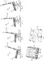
- the seating furniture chassis 100 comprises a height-adjustable seat 101 and a backrest 102.
- the seat 101 is coupled to a height adjustment mechanism 103, which in turn is coupled to threaded rods 104.
- the threaded rods 104 can be set in rotation by means of a drive means 105. When the threaded rods 104 rotate, the height of the seat surface 101 is changed. This is particularly good in the Figures 1A to 1D to recognize.
- the seat 101 When the seat 101 is adjusted in height, the seat 101 is inclined at the same time. When the seat 101 is lowered, the area of the seat facing the backrest 102 tilts downward relative to the area facing away from the backrest 102. When the seat 101 is raised, the seat inclines Backrest 102 facing area of the seat upwards relative to the area facing away from the backrest 102.
- the backrest 102 is inclined when the height of the seat surface 101 is adjusted. An upper region of the backrest 102 is moved forward relative to a lower region of the backrest 102 when the seat 101 is raised. When the seat 101 is lowered, the upper region of the backrest 102 is moved rearward relative to the lower region of the backrest 102.
- the drive means 105 sets a shaft (not shown) in rotation.
- the longitudinal axis of the shaft runs horizontally from one side of the seating frame to the side of the seating frame opposite this side.
- the sides are the sides arranged on the right and left in the normal position of use of the seating chassis. These are the sides on which neither the backrest is arranged nor on the opposite side of the backrest.
- the rotation of the shaft is transmitted to the threaded rods 104 by means of bevel gear 200. It is therefore possible that the longitudinal axes of the threaded rods 104 do not run parallel to the longitudinal axis of the shaft. Especially in Figure 2 it can be seen that the longitudinal axes of the threaded rods 104 run approximately at right angles to the longitudinal axis of the shaft.
- Figure 3 shows how the height adjustment mechanism 103 is coupled to the threaded rods 104, so that rotation of the threaded rods 104 results in a height adjustment of the seat 101.
Landscapes
- Health & Medical Sciences (AREA)
- General Health & Medical Sciences (AREA)
- Life Sciences & Earth Sciences (AREA)
- Animal Behavior & Ethology (AREA)
- Public Health (AREA)
- Veterinary Medicine (AREA)
- Dentistry (AREA)
- Legs For Furniture In General (AREA)
- Chairs For Special Purposes, Such As Reclining Chairs (AREA)
- Seats For Vehicles (AREA)
Description
- Die vorliegende Erfindung betrifft ein Sitzmöbelchassis mit einer höhenverstellbaren Sitzfläche gemäß dem Oberbegriff des ersten Anspruchs.
- Unter einem Sitzmöbelchassis wird im Rahmen dieser Erfindung insbesondere eine Konstruktion verstanden, die als Grundgerüst eines Sitzmöbels eingesetzt wird. Das Sitzmöbelchassis kann also beispielsweise eine Konstruktion aus Metall und/oder anderen Werkstoffen sein, an der Polster, Bezug und weitere Bauteile des Sitzmöbels befestigt werden können.
- Ein Sitzmöbelchassis mit einer höhenverstellbaren Sitzfläche ist aus dem Stand der Technik bereits bekannt. Die höhenverstellbare Sitzfläche ist vor allem vorteilhaft für körperlich eingeschränkte Benutzer. Eine relativ hohe Sitzfläche ermöglicht ein einfaches Aufstehen und Hinsetzen. Wenn der Benutzer sitzt, kann die Höhe der Sitzfläche verringert werden, sodass er eine bequeme Sitzposition einnehmen kann.
-
US 4,852,939 offenbart eine Höhenverstellung für ein Sitzmöbel. - Bekannte Mechaniken benötigen relativ viel Bauraum, sodass einigen Benutzern das Design derartiger Sitzmöbel nicht gefällt.
- Demgegenüber liegt der Erfindung die Aufgabe zugrunde, ein Sitzmöbelchassis mit einer weniger Bauraum benötigenden Mechanik und ein Sitzmöbel mit einem solchen Sitzmöbelchassis zu schaffen Diese Aufgabe wird durch ein Sitzmöbelchassis gemäß Anspruch 1 und ein Sitzmöbel gemäß Anspruch 13 gelöst. Ausführungsformen der Erfindung sind in den abhängigen Ansprüchen angegeben.
- Das Sitzmöbelchassis umfasst eine höhenverstellbare Sitzfläche, ein Antriebsmittel, eine Welle, einen Höhenverstellungsmechanismus und eine Gewindestange. Das Antriebsmittel ist mit der Welle gekoppelt und zur Übertragung eines Drehmoments über die Welle an die Gewindestange ausgebildet. Der Höhenverstellungsmechanismus ist so mit der Gewindestange und der Sitzfläche gekoppelt, dass eine Rotation der Gewindestange durch den Höhenverstellungsmechanismus in eine Höhenverstellung der Sitzfläche umgesetzt wird.
- Erfindungsgemäß ist vorgesehen, dass eine Längsachse der Welle nicht parallel zu einer Längsachse der Gewindestange angeordnet ist. Unter der Längsachse wird dabei insbesondere jeweils die Achse verstanden, in der die Welle beziehungsweise die Gewindestange die größte Ausdehnung aufweist. Die Längsachse kann beispielsweise bei einer Drehung der Welle bzw. der Gewindestange in Richtung des Drehimpulsvektors verlaufen.
- Die Gewindestange kann also mittels des Antriebsmittels in Rotation versetzt werden. Diese Rotation löst eine Höhenverstellung der Sitzfläche aus.
- Durch die nicht parallele Anordnung der beiden Längsachsen zueinander wird Bauraum eingespart, da die beiden relativ langen Bauteile sich nicht in derselben Richtung erstrecken.
- Versuche haben überraschenderweise gezeigt, dass eine derartige Anordnung ausreichend Stabilität für den Einsatz bei einem Sitzmöbelchassis bietet. Dies war nicht zu erwarten, da auf die Mechanik bei relativ schweren Benutzern eine enorme Belastung wirkt, insbesondere wenn der Benutzer sich auf die Sitzfläche setzt. Von höhenverstellbaren Tischmöbeln ist bereits bekannt, dass die Längsachse der Welle nicht parallel zur Längsachse der Gewindestange verläuft. Dort wird diese Mechanik jedoch nicht eingesetzt, um Bauraum einzusparen. Denn dieser ist bei Tischmöbeln üblicherweise ausreichend vorhanden. Außerdem treten bei Tischmöbeln keine vergleichbar große Belastungen der Mechanik auf.
- Nach einer Ausführungsform der Erfindung kann das Sitzmöbelchassis ein Kegelradgetriebe umfassen, das mit der Welle und der Gewindestange gekoppelt ist, sodass das Drehmoment von der Welle auf die Gewindestange über das Kegelradgetriebe übertragen werden kann. Das Kegelradgetriebe wird eingesetzt, da die Längsachsen der Welle und der Gewindestange nicht parallel zueinander angeordnet sind.
- Nach einer Ausführungsform der Erfindung kann das Kegelradgetriebe als schrägverzahntes Kegelradgetriebe ausgebildet sein. Dies hat den Vorteil einer besseren Drehmomentübertragung. Bevor die Verbindung zweier Zähne gelöst wird, treten bereits zwei andere Zähne miteinander in Kontakt.
- Erfindungsgemäß ist vorgesehen, dass das Sitzmöbelchassis eine weitere Gewindestange umfasst, die über die Welle mit dem Antriebsmittel gekoppelt ist. Die weitere Gewindestange kann ähnlich oder genauso ausgebildet sein wie die bereits zuvor erwähnte Gewindestange. Die Verwendung der weiteren Gewindestange erhöht die Stabilität der Mechanik.
- Nach einer Ausführungsform der Erfindung ist es möglich, dass eine Längsachse der weiteren Gewindestange nicht parallel zur Längsachse der Welle angeordnet ist. Es ist aber möglich, dass die Längsachsen der beiden Gewindestangen parallel zueinander angeordnet sind.
- Nach einer Ausführungsform der Erfindung kann das Sitzmöbelchassis ein weiteres Kegelradgetriebe umfassen, das mit der weiteren Gewindestange und der Welle gekoppelt ist.
- Nach einer Ausführungsform der Erfindung kann das weitere Kegelradgetriebe als schrägverzahntes Kegelradgetriebe ausgebildet sein.
- Erfindungsgemäß ist vorgesehen, dass der Höhenverstellungsmechanismus so mit der Gewindestange und der Sitzfläche gekoppelt ist, dass bei einer Höhenverstellung der Sitzfläche gleichzeitig eine Neigung der Sitzfläche erfolgt. Dies ist insbesondere vorteilhaft, um einen Benutzer das Aufstehen und das Hinsetzen zu erleichtern.
- Nach einer Ausführungsform der Erfindung kann bei einer Anhebung der Sitzfläche eine Neigung der Sitzfläche nach vorne ausgelöst werden. Unter dem Begriff "vorne" wird dabei insbesondere die einer Rückenlehne gegenüberliegende Seite des Sitzmöbelchassis verstanden. Eine Neigung der Sitzfläche nach vorne kann bedeuten, dass der vordere Bereich der Sitzfläche relativ zum hinteren Bereich der Sitzfläche abgesenkt wird und/oder der hintere Bereich der Sitzfläche relativ zum vorderen Bereich der Sitzfläche angehoben wird.
- Nach einer Ausführungsform der Erfindung kann bei einer Absenkung der Sitzfläche eine Neigung der Sitzfläche nach hinten ausgelöst werden. Eine Neigung der Sitzfläche nach hinten kann bedeuten, dass der vordere Bereich der Sitzfläche relativ zum hinteren Bereich angehoben wird und/oder der hintere Bereich der Sitzfläche relativ zum vorderen Bereich abgesenkt wird.
- Nach einer Ausführungsform der Erfindung kann das Sitzmöbelchassis eine Rückenlehne umfassen. Die Rückenlehne kann so mit dem Höhenverstellungsmechanismus gekoppelt sein, dass bei einer Höhenverstellung der Sitzfläche eine Neigung der Rückenlehne erfolgt.
- Nach einer Ausführungsform der Erfindung kann bei einer Anhebung der Sitzfläche eine Neigung der Rückenlehne nach vorne ausgelöst werden. Eine Neigung der Rückenlehne nach vorne kann bedeuten, dass ein oberer Bereich der Rückenlehne nach vorne bewegt wird und/oder ein unterer Bereich der Rückenlehne nach hinten bewegt wird.
- Nach einer Ausführungsform der Erfindung kann bei einer Absenkung der Sitzfläche eine Neigung der Rückenlehne nach hinten ausgelöst werden. Eine Neigung der Rückenlehne nach hinten kann bedeuten, dass ein oberer Bereich der Rückenlehne nach hinten bewegt wird und/oder ein unterer Bereich der Rückenlehne nach vorne bewegt wird.
- Nach einer Ausführungsform der Erfindung kann die Längsachse der Welle in etwa rechtwinklig zur Längsachse der Gewindestange angeordnet sein. Diese Anordnung ist besonders bauraumsparend. Weitere Merkmale und Vorteile der vorliegenden Erfindung werden deutlich anhand der nachfolgenden Beschreibung bevorzugter Ausführungsbeispiele unter Bezugnahme auf die beiliegenden Abbildungen. Dabei werden für gleiche oder ähnliche Bauteile und für Bauteile mit den gleichen oder ähnlichen Funktionen dieselben Bezugszeichen verwendet. Darin zeigen:
- Fig. 1
- schematische Darstellungen eines Sitzmöbelchassis nach
- A-D
- einer Ausführungsform der Erfindung;
- Fig. 2
- eine schematische Darstellung des Antriebsmittels, der Gewindestangen und der Kegelradgetriebe von der Rückseite des Sitzmöbelchassis; und
- Fig. 3
- eine schematische Darstellung des Antriebsmittels, einer der Gewindestangen und des Höhenverstellungsmittels in einer Seitenansicht.
- Das Sitzmöbelchassis 100 umfasst eine höhenverstellbare Sitzfläche 101 und eine Rückenlehne 102. Die Sitzfläche 101 ist mit einem Höhenverstellungsmechanismus 103 gekoppelt, der wiederum mit Gewindestangen 104 gekoppelt ist. Die Gewindestangen 104 können mittels eines Antriebsmittels 105 in Rotation versetzt werden. Bei Rotation der Gewindestangen 104 wird die Höhe der Sitzfläche 101 verändert. Dies ist besonders gut in den
Figuren 1A bis 1D zu erkennen. - Bei einer Höhenverstellung der Sitzfläche 101 erfolgt gleichzeitig eine Neigung der Sitzfläche 101. Wenn die Sitzfläche 101 abgesenkt wird, neigt sich der der Rückenlehne 102 zugewandte Bereich der Sitzfläche nach unten relativ zum der Rückenlehne 102 abgewandten Bereich. Wenn die Sitzfläche 101 angehoben wird, neigt sich der der Rückenlehne 102 zugewandte Bereich der Sitzfläche nach oben relativ zum der Rückenlehne 102 abgewandten Bereich.
- Außerdem erfolgt eine Neigung der Rückenlehne 102, wenn die Höhe der Sitzfläche 101 verstellt wird. Ein oberer Bereich der Rückenlehne 102 wird relativ zu einem unteren Bereich der Rückenlehne 102 nach vorne bewegt, wenn die Sitzfläche 101 angehoben wird. Wenn die Sitzfläche 101 abgesenkt wird, wird der obere Bereich der Rückenlehne 102 relativ zum unteren Bereich der Rückenlehne 102 nach hinten bewegt.
- Das Antriebsmittel 105 versetzt eine Welle (nicht dargestellt) in Rotation. Die Längsachse der Welle verläuft dabei horizontal von einer Seite des Sitzmöbelchassis zur dieser Seite gegenüberliegenden Seite des Sitzmöbelchassis. Die Seiten sind dabei die in der üblichen Gebrauchsstellung des Sitzmöbelchassis rechts und links angeordneten Seiten. Dies sind die Seiten, an denen weder die Rückenlehne angeordnet ist noch die der Rückenlehne gegenüber liegenden.
- Die Rotation der Welle wird mittels Kegelradgetriebe 200 auf die Gewindestangen 104 übertragen. Daher ist es möglich, dass die Längsachsen der Gewindestangen 104 nicht parallel zur Längsachse der Welle verlaufen. Insbesondere in
Figur 2 ist ersichtlich, dass die Längsachsen der Gewindestangen 104 in etwa rechtwinklig zur Längsachse der Welle verlaufen. - In
Figur 3 ist dargestellt, wie der Höhenverstellungsmechanismus 103 mit den Gewindestangen 104 gekoppelt ist, sodass eine Rotation der Gewindestangen 104 eine Höhenverstellung der Sitzfläche 101 zur Folge hat.
Claims (13)
- Sitzmöbelchassis (100), umfassend eine höhenverstellbare Sitzfläche (101), ein Antriebsmittel (105), eine Welle, einen Höhenverstellungsmechanismus (103) und eine Gewindestange (104), wobei das Antriebsmittel (105) mit der Welle gekoppelt und zur Übertragung eines Drehmoments über die Welle an die Gewindestange (104) ausgebildet ist, und wobei der Höhenverstellungsmechanismus (103) so mit der Gewindestange (104) und der Sitzfläche (101) gekoppelt ist, dass eine Rotation der Gewindestange (104) durch den Höhenverstellungsmechanismus (103) in eine Höhenverstellung der Sitzfläche (101) umgesetzt wird, wobei
eine Längsachse der Welle nicht parallel zu einer Längsachse der Gewindestange (104) angeordnet ist, wobei der Höhenverstellungsmechanismus (103) so mit der Gewindestange (104) und der Sitzfläche (101) gekoppelt ist, dass bei einer Höhenverstellung der Sitzfläche (101) gleichzeitig eine Neigung der Sitzfläche (101) erfolgt, dadurch gekennzeichnet, dass das Sitzmöbelchassis (100) eine weitere Gewindestange (104) umfasst, die über die Welle mit dem Antriebsmittel (105) gekoppelt ist. - Sitzmöbelchassis (100) nach Anspruch 1, dadurch gekennzeichnet, dass das Sitzmöbelchassis (100) ein Kegelradgetriebe (200) umfasst, das mit der Welle und der Gewindestange (104) gekoppelt ist, sodass das Drehmoment von der Welle auf die Gewindestange (104) über das Kegelradgetriebe (200) übertragbar ist.
- Sitzmöbelchassis (100) nach Anspruch 2, dadurch gekennzeichnet, dass das Kegelradgetriebe (200) als schrägverzahntes Kegelradgetriebe ausgebildet ist.
- Sitzmöbelchassis (100) nach dem vorherigen Anspruch, dadurch gekennzeichnet, dass eine Längsachse der weiteren Gewindestange (104) nicht parallel zur Längsachse der Welle angeordnet ist.
- Sitzmöbelchassis (100) nach einem der Ansprüche 2-4, dadurch gekennzeichnet, dass das Sitzmöbelchassis (100) ein weiteres Kegelradgetriebe (200) umfasst, das mit der weiteren Gewindestange (104) und mit der Welle gekoppelt ist.
- Sitzmöbelchassis (100) nach dem vorherigen Anspruch, dadurch gekennzeichnet, dass das weitere Kegelradgetriebe (200) als schrägverzahntes Kegelradgetriebe ausgebildet ist.
- Sitzmöbelchassis (100) nach einem der vorherigen Ansprüche, dadurch gekennzeichnet, dass bei einer Anhebung der Sitzfläche (101) eine Neigung der Sitzfläche (101) nach vorne ausgelöst wird.
- Sitzmöbelchassis (100) nach einem der vorherigen Ansprüche, dadurch gekennzeichnet, dass bei einer Absenkung der Sitzfläche (101) eine Neigung der Sitzfläche (101) nach hinten ausgelöst wird.
- Sitzmöbelchassis (100) nach zumindest einem der vorherigen Ansprüche, dadurch gekennzeichnet, dass das Sitzmöbelchassis (100) eine Rückenlehne (102) umfasst, wobei die Rückenlehne (102) so mit dem Höhenverstellungsmechanismus (103) gekoppelt ist, dass bei einer Höhenverstellung der Sitzfläche (101) eine Neigung der Rückenlehne (102) erfolgt.
- Sitzmöbelchassis (100) nach dem vorherigen Anspruch, dadurch gekennzeichnet, dass bei einer Anhebung der Sitzfläche (101) eine Neigung der Rückenlehne (102) nach vorne ausgelöst wird.
- Sitzmöbelchassis (100) nach einem der beiden vorherigen Ansprüche, dadurch gekennzeichnet, dass bei einer Absenkung der Sitzfläche (101) eine Neigung der Rückenlehne (102) nach hinten ausgelöst wird.
- Sitzmöbelchassis (100) nach einem der vorherigen Ansprüche, dadurch gekennzeichnet, dass die Längsachse der Welle in etwa rechtwinklig zur Längsachse der Gewindestange (104) angeordnet ist.
- Sitzmöbel, umfassend ein Sitzmöbelchassis (100) nach einem der vorherigen Ansprüche.
Priority Applications (1)
| Application Number | Priority Date | Filing Date | Title |
|---|---|---|---|
| PL16700289T PL3244859T3 (pl) | 2015-01-15 | 2016-01-06 | Podstawa mebla do siedzenia z powierzchnią siedzenia regulowaną w kierunku wysokości |
Applications Claiming Priority (2)
| Application Number | Priority Date | Filing Date | Title |
|---|---|---|---|
| DE202015100170.3U DE202015100170U1 (de) | 2015-01-15 | 2015-01-15 | Sitzmöbelchassis mit einer höhenverstellbaren Sitzfläche |
| PCT/EP2016/050129 WO2016113160A1 (de) | 2015-01-15 | 2016-01-06 | Sitzmöbelchassis mit einer höhenverstellbaren sitzfläche |
Publications (2)
| Publication Number | Publication Date |
|---|---|
| EP3244859A1 EP3244859A1 (de) | 2017-11-22 |
| EP3244859B1 true EP3244859B1 (de) | 2020-04-29 |
Family
ID=55083413
Family Applications (1)
| Application Number | Title | Priority Date | Filing Date |
|---|---|---|---|
| EP16700289.8A Active EP3244859B1 (de) | 2015-01-15 | 2016-01-06 | Sitzmöbelchassis mit einer höhenverstellbaren sitzfläche |
Country Status (9)
| Country | Link |
|---|---|
| US (1) | US10092467B2 (de) |
| EP (1) | EP3244859B1 (de) |
| CN (1) | CN107072859A (de) |
| CA (1) | CA2965876C (de) |
| DE (1) | DE202015100170U1 (de) |
| DK (1) | DK3244859T3 (de) |
| ES (1) | ES2805742T3 (de) |
| PL (1) | PL3244859T3 (de) |
| WO (1) | WO2016113160A1 (de) |
Families Citing this family (6)
| Publication number | Priority date | Publication date | Assignee | Title |
|---|---|---|---|---|
| EP2823796B1 (de) * | 2013-07-12 | 2017-08-16 | Permobil AB | Rollstuhl mit Kippfunktion |
| US12350207B2 (en) * | 2014-07-14 | 2025-07-08 | Exokinetics, Inc. | Lifting mechanism and chairs |
| JP6870952B2 (ja) * | 2016-10-18 | 2021-05-12 | 株式会社日吉技術産業 | 昇降式座椅子 |
| US12290482B2 (en) | 2016-11-10 | 2025-05-06 | Exokinetics, Inc. | Elevating walker chair and components |
| EP3381429B1 (de) * | 2017-03-31 | 2020-05-06 | Permobil AB | Kippanordnung für einen elektrisch angetriebenen rollstuhl und ein elektrisch angetriebener rollstuhl damit |
| WO2019161868A1 (en) * | 2018-02-26 | 2019-08-29 | Global FabTech (Shanghai) Company Limited | Seating furniture chassis and method of operation |
Family Cites Families (24)
| Publication number | Priority date | Publication date | Assignee | Title |
|---|---|---|---|---|
| US597278A (en) * | 1898-01-11 | fischer | ||
| US2608239A (en) * | 1949-09-09 | 1952-08-26 | Gorden Fred | Chair |
| DE2101775A1 (de) | 1971-01-15 | 1972-07-20 | Posselt H | Drehstuhl mit Höhenverstellung |
| US3765720A (en) * | 1971-07-02 | 1973-10-16 | Nissan Motor | Position adjustable support mechanism |
| US3763507A (en) * | 1971-08-27 | 1973-10-09 | Miller Herman Inc | Pediatric bed |
| US4015812A (en) * | 1975-10-28 | 1977-04-05 | International Telephone And Telegraph Corporation | Seat adjustment mechanism |
| US4852939A (en) * | 1987-10-23 | 1989-08-01 | Orthokinetics, Inc. | Device for converting a recliner chair to a recliner-lift chair |
| CA1299989C (en) * | 1988-05-20 | 1992-05-05 | Larry P. Lapointe | Recliner chair lift base assembly |
| US5165753A (en) * | 1991-01-02 | 1992-11-24 | Henderson Eldred D | Elevator chair apparatus |
| US5556163A (en) * | 1994-08-17 | 1996-09-17 | Eac Corporation | Automatically adjustable office and task chairs |
| US5806920A (en) * | 1994-11-17 | 1998-09-15 | Blount; Eric D. | Fully reclinable elevator lift chair with ottoman |
| CN2233696Y (zh) * | 1995-08-10 | 1996-08-28 | 徐灯铨 | 躺椅的起身辅助装置 |
| JPH09294791A (ja) * | 1996-05-02 | 1997-11-18 | Matoba Denki Seisakusho:Kk | 健康チェア− |
| CN2294717Y (zh) * | 1997-05-15 | 1998-10-21 | 施金木 | 一种可辅助站立的轮椅 |
| WO2002032262A1 (en) * | 2000-10-16 | 2002-04-25 | Kokuyo Co., Ltd. | Chair |
| US6637818B2 (en) * | 2001-08-24 | 2003-10-28 | Jerry Wayne Williams | Portable lift seat apparatus |
| US7341310B1 (en) * | 2005-06-24 | 2008-03-11 | Betty Ross | Office chair with automated height adjustment |
| WO2008005050A2 (en) * | 2006-06-30 | 2008-01-10 | I-Trust Better Life Corp. | Support frame for a lift chair |
| CN101214187A (zh) * | 2007-12-30 | 2008-07-09 | 陈利忠 | 采血椅的升降装置 |
| CN201341635Y (zh) * | 2008-12-08 | 2009-11-11 | 沈阳师范大学 | 高度可调布艺椅 |
| WO2011063524A1 (en) * | 2009-11-26 | 2011-06-03 | Wright Hi/Lo Solutions Ltd. | Chair with a height-adjustable seat |
| CN202104564U (zh) * | 2011-03-10 | 2012-01-11 | 林志强 | 一种电动升降装置 |
| CN203483124U (zh) * | 2013-08-13 | 2014-03-19 | 北斗星家具(北京)有限公司 | 一种升降椅 |
| DE102015214301A1 (de) * | 2015-07-28 | 2017-02-02 | Stabilus Gmbh | Möbelstück und Stellanordnung, insbesondere für eine Lehnenverstellung |
-
2015
- 2015-01-15 DE DE202015100170.3U patent/DE202015100170U1/de not_active Expired - Lifetime
-
2016
- 2016-01-06 ES ES16700289T patent/ES2805742T3/es active Active
- 2016-01-06 US US15/517,048 patent/US10092467B2/en active Active
- 2016-01-06 WO PCT/EP2016/050129 patent/WO2016113160A1/de not_active Ceased
- 2016-01-06 CN CN201680003352.XA patent/CN107072859A/zh active Pending
- 2016-01-06 DK DK16700289.8T patent/DK3244859T3/da active
- 2016-01-06 EP EP16700289.8A patent/EP3244859B1/de active Active
- 2016-01-06 PL PL16700289T patent/PL3244859T3/pl unknown
- 2016-01-06 CA CA2965876A patent/CA2965876C/en active Active
Non-Patent Citations (1)
| Title |
|---|
| None * |
Also Published As
| Publication number | Publication date |
|---|---|
| DE202015100170U1 (de) | 2016-04-18 |
| CN107072859A (zh) | 2017-08-18 |
| US20170296411A1 (en) | 2017-10-19 |
| CA2965876A1 (en) | 2016-07-21 |
| DK3244859T3 (da) | 2020-07-20 |
| ES2805742T3 (es) | 2021-02-15 |
| CA2965876C (en) | 2023-04-25 |
| EP3244859A1 (de) | 2017-11-22 |
| WO2016113160A1 (de) | 2016-07-21 |
| US10092467B2 (en) | 2018-10-09 |
| PL3244859T3 (pl) | 2020-10-19 |
Similar Documents
| Publication | Publication Date | Title |
|---|---|---|
| DE102014103780B3 (de) | Stuhl | |
| EP2337704B1 (de) | Untergestell eines kraftfahrzeugsitzes mit zwei schienenpaaren, schwingen und einem sitzträger | |
| DE68902427T2 (de) | Motorisch verstellbare armlehne. | |
| EP2818361B1 (de) | Fahrzeugsitz und Nutzkraftfahrzeug mit wenigstens einem Fahrzeugsitz | |
| WO2016113160A1 (de) | Sitzmöbelchassis mit einer höhenverstellbaren sitzfläche | |
| DE102018101721A1 (de) | Sitzmöbel mit höhenverstellbarem Kopfteil | |
| EP3178691B1 (de) | Federungsvorrichtung | |
| DE2102108A1 (de) | Sitz, insbesondere Fahrzeugsitz | |
| EP1360085B1 (de) | Sitz, insbesondere Fahrzeugsitz, vorzugsweise Fluggastsitz | |
| DE1429438B2 (de) | Neigungsverstellvorrichtung fuer die rueckenlehne von sitzen insbesondere kraftfahrzeugsitzen | |
| EP1836070B1 (de) | Fahrzeugsitz | |
| EP2360051B1 (de) | Fahrzeugsitz mit einem Sitzversteller | |
| DE102017208689A1 (de) | Fahrzeugsitzkonsole, Fahrzeugsitz und Fahrzeug | |
| DE102015116108B4 (de) | Fahrzeugsitzanordnung, Kraftfahrzeugsitz und Befestigungsanordnung für ein Fahrzeugsitzpolster | |
| DE102013001805B3 (de) | Neigungseinsteller für einen Fahrzeugsitz und Fahrzeugsitz | |
| DE102006049676B4 (de) | Stuhl mit neigbarem Sitz | |
| DE2048460A1 (de) | Dreh oder Kippeinrichtung fur einen kippbaren Stuhlsitz | |
| DE102017129556B4 (de) | Fahrzeugsitz mit Verstelleinrichtung | |
| EP2921078A1 (de) | Sitzmöbel mit einem Chassis und einem gegenüber dem Chassis schwenkbaren Fußteil | |
| EP3893696B1 (de) | Sitzmöbel mit einer lordosenstützvorrichtung | |
| DE102019129159B4 (de) | Vorrichtung zur Einstellung einer Sitzposition, Fahrzeugsitz | |
| DE202015105851U1 (de) | Sitzmöbelchassis | |
| DE1150586B (de) | Gelenkbeschlag fuer Sitze mit verstellbarer Lehne, insbesondere fuer Kraftfahrzeuge | |
| EP3100642B1 (de) | Mechanismus für einen stuhl mit einer synchronmechanik; verfahren zur gewichtseinstellung für ein verbessertes dynamisches sitzgefühl des sitznutzers mittels eines mechanismus für einen stuhl mit einer synchronmechanik | |
| EP2596721B1 (de) | Stuhl und Sitz-Anordnung |
Legal Events
| Date | Code | Title | Description |
|---|---|---|---|
| STAA | Information on the status of an ep patent application or granted ep patent |
Free format text: STATUS: THE INTERNATIONAL PUBLICATION HAS BEEN MADE |
|
| PUAI | Public reference made under article 153(3) epc to a published international application that has entered the european phase |
Free format text: ORIGINAL CODE: 0009012 |
|
| STAA | Information on the status of an ep patent application or granted ep patent |
Free format text: STATUS: REQUEST FOR EXAMINATION WAS MADE |
|
| 17P | Request for examination filed |
Effective date: 20170816 |
|
| AK | Designated contracting states |
Kind code of ref document: A1 Designated state(s): AL AT BE BG CH CY CZ DE DK EE ES FI FR GB GR HR HU IE IS IT LI LT LU LV MC MK MT NL NO PL PT RO RS SE SI SK SM TR |
|
| AX | Request for extension of the european patent |
Extension state: BA ME |
|
| DAV | Request for validation of the european patent (deleted) | ||
| DAX | Request for extension of the european patent (deleted) | ||
| STAA | Information on the status of an ep patent application or granted ep patent |
Free format text: STATUS: EXAMINATION IS IN PROGRESS |
|
| 17Q | First examination report despatched |
Effective date: 20190329 |
|
| GRAP | Despatch of communication of intention to grant a patent |
Free format text: ORIGINAL CODE: EPIDOSNIGR1 |
|
| STAA | Information on the status of an ep patent application or granted ep patent |
Free format text: STATUS: GRANT OF PATENT IS INTENDED |
|
| INTG | Intention to grant announced |
Effective date: 20191206 |
|
| GRAS | Grant fee paid |
Free format text: ORIGINAL CODE: EPIDOSNIGR3 |
|
| GRAA | (expected) grant |
Free format text: ORIGINAL CODE: 0009210 |
|
| STAA | Information on the status of an ep patent application or granted ep patent |
Free format text: STATUS: THE PATENT HAS BEEN GRANTED |
|
| AK | Designated contracting states |
Kind code of ref document: B1 Designated state(s): AL AT BE BG CH CY CZ DE DK EE ES FI FR GB GR HR HU IE IS IT LI LT LU LV MC MK MT NL NO PL PT RO RS SE SI SK SM TR |
|
| REG | Reference to a national code |
Ref country code: GB Ref legal event code: FG4D Free format text: NOT ENGLISH |
|
| REG | Reference to a national code |
Ref country code: CH Ref legal event code: EP |
|
| REG | Reference to a national code |
Ref country code: AT Ref legal event code: REF Ref document number: 1262231 Country of ref document: AT Kind code of ref document: T Effective date: 20200515 |
|
| REG | Reference to a national code |
Ref country code: DE Ref legal event code: R096 Ref document number: 502016009741 Country of ref document: DE |
|
| REG | Reference to a national code |
Ref country code: IE Ref legal event code: FG4D Free format text: LANGUAGE OF EP DOCUMENT: GERMAN |
|
| REG | Reference to a national code |
Ref country code: DK Ref legal event code: T3 Effective date: 20200715 |
|
| REG | Reference to a national code |
Ref country code: NL Ref legal event code: FP |
|
| REG | Reference to a national code |
Ref country code: NO Ref legal event code: T2 Effective date: 20200429 |
|
| REG | Reference to a national code |
Ref country code: LT Ref legal event code: MG4D |
|
| PG25 | Lapsed in a contracting state [announced via postgrant information from national office to epo] |
Ref country code: LT Free format text: LAPSE BECAUSE OF FAILURE TO SUBMIT A TRANSLATION OF THE DESCRIPTION OR TO PAY THE FEE WITHIN THE PRESCRIBED TIME-LIMIT Effective date: 20200429 Ref country code: GR Free format text: LAPSE BECAUSE OF FAILURE TO SUBMIT A TRANSLATION OF THE DESCRIPTION OR TO PAY THE FEE WITHIN THE PRESCRIBED TIME-LIMIT Effective date: 20200730 Ref country code: FI Free format text: LAPSE BECAUSE OF FAILURE TO SUBMIT A TRANSLATION OF THE DESCRIPTION OR TO PAY THE FEE WITHIN THE PRESCRIBED TIME-LIMIT Effective date: 20200429 Ref country code: IS Free format text: LAPSE BECAUSE OF FAILURE TO SUBMIT A TRANSLATION OF THE DESCRIPTION OR TO PAY THE FEE WITHIN THE PRESCRIBED TIME-LIMIT Effective date: 20200829 Ref country code: SE Free format text: LAPSE BECAUSE OF FAILURE TO SUBMIT A TRANSLATION OF THE DESCRIPTION OR TO PAY THE FEE WITHIN THE PRESCRIBED TIME-LIMIT Effective date: 20200429 Ref country code: PT Free format text: LAPSE BECAUSE OF FAILURE TO SUBMIT A TRANSLATION OF THE DESCRIPTION OR TO PAY THE FEE WITHIN THE PRESCRIBED TIME-LIMIT Effective date: 20200831 |
|
| PG25 | Lapsed in a contracting state [announced via postgrant information from national office to epo] |
Ref country code: RS Free format text: LAPSE BECAUSE OF FAILURE TO SUBMIT A TRANSLATION OF THE DESCRIPTION OR TO PAY THE FEE WITHIN THE PRESCRIBED TIME-LIMIT Effective date: 20200429 Ref country code: BG Free format text: LAPSE BECAUSE OF FAILURE TO SUBMIT A TRANSLATION OF THE DESCRIPTION OR TO PAY THE FEE WITHIN THE PRESCRIBED TIME-LIMIT Effective date: 20200729 Ref country code: LV Free format text: LAPSE BECAUSE OF FAILURE TO SUBMIT A TRANSLATION OF THE DESCRIPTION OR TO PAY THE FEE WITHIN THE PRESCRIBED TIME-LIMIT Effective date: 20200429 Ref country code: HR Free format text: LAPSE BECAUSE OF FAILURE TO SUBMIT A TRANSLATION OF THE DESCRIPTION OR TO PAY THE FEE WITHIN THE PRESCRIBED TIME-LIMIT Effective date: 20200429 |
|
| PG25 | Lapsed in a contracting state [announced via postgrant information from national office to epo] |
Ref country code: AL Free format text: LAPSE BECAUSE OF FAILURE TO SUBMIT A TRANSLATION OF THE DESCRIPTION OR TO PAY THE FEE WITHIN THE PRESCRIBED TIME-LIMIT Effective date: 20200429 |
|
| PG25 | Lapsed in a contracting state [announced via postgrant information from national office to epo] |
Ref country code: CZ Free format text: LAPSE BECAUSE OF FAILURE TO SUBMIT A TRANSLATION OF THE DESCRIPTION OR TO PAY THE FEE WITHIN THE PRESCRIBED TIME-LIMIT Effective date: 20200429 Ref country code: RO Free format text: LAPSE BECAUSE OF FAILURE TO SUBMIT A TRANSLATION OF THE DESCRIPTION OR TO PAY THE FEE WITHIN THE PRESCRIBED TIME-LIMIT Effective date: 20200429 Ref country code: EE Free format text: LAPSE BECAUSE OF FAILURE TO SUBMIT A TRANSLATION OF THE DESCRIPTION OR TO PAY THE FEE WITHIN THE PRESCRIBED TIME-LIMIT Effective date: 20200429 Ref country code: SM Free format text: LAPSE BECAUSE OF FAILURE TO SUBMIT A TRANSLATION OF THE DESCRIPTION OR TO PAY THE FEE WITHIN THE PRESCRIBED TIME-LIMIT Effective date: 20200429 |
|
| REG | Reference to a national code |
Ref country code: DE Ref legal event code: R097 Ref document number: 502016009741 Country of ref document: DE |
|
| REG | Reference to a national code |
Ref country code: ES Ref legal event code: FG2A Ref document number: 2805742 Country of ref document: ES Kind code of ref document: T3 Effective date: 20210215 |
|
| PG25 | Lapsed in a contracting state [announced via postgrant information from national office to epo] |
Ref country code: SK Free format text: LAPSE BECAUSE OF FAILURE TO SUBMIT A TRANSLATION OF THE DESCRIPTION OR TO PAY THE FEE WITHIN THE PRESCRIBED TIME-LIMIT Effective date: 20200429 |
|
| PLBE | No opposition filed within time limit |
Free format text: ORIGINAL CODE: 0009261 |
|
| STAA | Information on the status of an ep patent application or granted ep patent |
Free format text: STATUS: NO OPPOSITION FILED WITHIN TIME LIMIT |
|
| 26N | No opposition filed |
Effective date: 20210201 |
|
| PG25 | Lapsed in a contracting state [announced via postgrant information from national office to epo] |
Ref country code: SI Free format text: LAPSE BECAUSE OF FAILURE TO SUBMIT A TRANSLATION OF THE DESCRIPTION OR TO PAY THE FEE WITHIN THE PRESCRIBED TIME-LIMIT Effective date: 20200429 |
|
| PG25 | Lapsed in a contracting state [announced via postgrant information from national office to epo] |
Ref country code: MC Free format text: LAPSE BECAUSE OF FAILURE TO SUBMIT A TRANSLATION OF THE DESCRIPTION OR TO PAY THE FEE WITHIN THE PRESCRIBED TIME-LIMIT Effective date: 20200429 |
|
| REG | Reference to a national code |
Ref country code: CH Ref legal event code: PL |
|
| GBPC | Gb: european patent ceased through non-payment of renewal fee |
Effective date: 20210106 |
|
| PG25 | Lapsed in a contracting state [announced via postgrant information from national office to epo] |
Ref country code: LU Free format text: LAPSE BECAUSE OF NON-PAYMENT OF DUE FEES Effective date: 20210106 |
|
| PG25 | Lapsed in a contracting state [announced via postgrant information from national office to epo] |
Ref country code: LI Free format text: LAPSE BECAUSE OF NON-PAYMENT OF DUE FEES Effective date: 20210131 Ref country code: GB Free format text: LAPSE BECAUSE OF NON-PAYMENT OF DUE FEES Effective date: 20210106 Ref country code: CH Free format text: LAPSE BECAUSE OF NON-PAYMENT OF DUE FEES Effective date: 20210131 |
|
| PG25 | Lapsed in a contracting state [announced via postgrant information from national office to epo] |
Ref country code: IE Free format text: LAPSE BECAUSE OF NON-PAYMENT OF DUE FEES Effective date: 20210106 |
|
| REG | Reference to a national code |
Ref country code: AT Ref legal event code: MM01 Ref document number: 1262231 Country of ref document: AT Kind code of ref document: T Effective date: 20210106 |
|
| PG25 | Lapsed in a contracting state [announced via postgrant information from national office to epo] |
Ref country code: AT Free format text: LAPSE BECAUSE OF NON-PAYMENT OF DUE FEES Effective date: 20210106 |
|
| PG25 | Lapsed in a contracting state [announced via postgrant information from national office to epo] |
Ref country code: HU Free format text: LAPSE BECAUSE OF FAILURE TO SUBMIT A TRANSLATION OF THE DESCRIPTION OR TO PAY THE FEE WITHIN THE PRESCRIBED TIME-LIMIT; INVALID AB INITIO Effective date: 20160106 |
|
| PG25 | Lapsed in a contracting state [announced via postgrant information from national office to epo] |
Ref country code: CY Free format text: LAPSE BECAUSE OF FAILURE TO SUBMIT A TRANSLATION OF THE DESCRIPTION OR TO PAY THE FEE WITHIN THE PRESCRIBED TIME-LIMIT Effective date: 20200429 |
|
| P01 | Opt-out of the competence of the unified patent court (upc) registered |
Effective date: 20230616 |
|
| PG25 | Lapsed in a contracting state [announced via postgrant information from national office to epo] |
Ref country code: MK Free format text: LAPSE BECAUSE OF FAILURE TO SUBMIT A TRANSLATION OF THE DESCRIPTION OR TO PAY THE FEE WITHIN THE PRESCRIBED TIME-LIMIT Effective date: 20200429 |
|
| PG25 | Lapsed in a contracting state [announced via postgrant information from national office to epo] |
Ref country code: MT Free format text: LAPSE BECAUSE OF FAILURE TO SUBMIT A TRANSLATION OF THE DESCRIPTION OR TO PAY THE FEE WITHIN THE PRESCRIBED TIME-LIMIT Effective date: 20200429 |
|
| PGFP | Annual fee paid to national office [announced via postgrant information from national office to epo] |
Ref country code: NL Payment date: 20260121 Year of fee payment: 11 |
|
| PGFP | Annual fee paid to national office [announced via postgrant information from national office to epo] |
Ref country code: ES Payment date: 20260227 Year of fee payment: 11 |
|
| PGFP | Annual fee paid to national office [announced via postgrant information from national office to epo] |
Ref country code: NO Payment date: 20260123 Year of fee payment: 11 Ref country code: DE Payment date: 20260131 Year of fee payment: 11 Ref country code: DK Payment date: 20260126 Year of fee payment: 11 |
|
| PGFP | Annual fee paid to national office [announced via postgrant information from national office to epo] |
Ref country code: IT Payment date: 20260123 Year of fee payment: 11 Ref country code: BE Payment date: 20260121 Year of fee payment: 11 |
|
| PGFP | Annual fee paid to national office [announced via postgrant information from national office to epo] |
Ref country code: FR Payment date: 20260123 Year of fee payment: 11 |
|
| PGFP | Annual fee paid to national office [announced via postgrant information from national office to epo] |
Ref country code: TR Payment date: 20260105 Year of fee payment: 11 |
|
| PGFP | Annual fee paid to national office [announced via postgrant information from national office to epo] |
Ref country code: PL Payment date: 20260102 Year of fee payment: 11 |