EP3245079B1 - Fahrzeugluftreifen mit schallabsorbierendem mittel - Google Patents
Fahrzeugluftreifen mit schallabsorbierendem mittel Download PDFInfo
- Publication number
- EP3245079B1 EP3245079B1 EP15795140.1A EP15795140A EP3245079B1 EP 3245079 B1 EP3245079 B1 EP 3245079B1 EP 15795140 A EP15795140 A EP 15795140A EP 3245079 B1 EP3245079 B1 EP 3245079B1
- Authority
- EP
- European Patent Office
- Prior art keywords
- sealant
- separating layer
- pneumatic vehicle
- vehicle tyre
- tyre according
- Prior art date
- Legal status (The legal status is an assumption and is not a legal conclusion. Google has not performed a legal analysis and makes no representation as to the accuracy of the status listed.)
- Active
Links
Images


Classifications
-
- B—PERFORMING OPERATIONS; TRANSPORTING
- B60—VEHICLES IN GENERAL
- B60C—VEHICLE TYRES; TYRE INFLATION; TYRE CHANGING; CONNECTING VALVES TO INFLATABLE ELASTIC BODIES IN GENERAL; DEVICES OR ARRANGEMENTS RELATED TO TYRES
- B60C19/00—Tyre parts or constructions not otherwise provided for
- B60C19/002—Noise damping elements provided in the tyre structure or attached thereto, e.g. in the tyre interior
-
- B—PERFORMING OPERATIONS; TRANSPORTING
- B29—WORKING OF PLASTICS; WORKING OF SUBSTANCES IN A PLASTIC STATE IN GENERAL
- B29D—PRODUCING PARTICULAR ARTICLES FROM PLASTICS OR FROM SUBSTANCES IN A PLASTIC STATE
- B29D30/00—Producing pneumatic or solid tyres or parts thereof
- B29D30/06—Pneumatic tyres or parts thereof (e.g. produced by casting, moulding, compression moulding, injection moulding, centrifugal casting)
- B29D30/0681—Parts of pneumatic tyres; accessories, auxiliary operations
- B29D30/0685—Incorporating auto-repairing or self-sealing arrangements or agents on or into tyres
-
- B—PERFORMING OPERATIONS; TRANSPORTING
- B60—VEHICLES IN GENERAL
- B60C—VEHICLE TYRES; TYRE INFLATION; TYRE CHANGING; CONNECTING VALVES TO INFLATABLE ELASTIC BODIES IN GENERAL; DEVICES OR ARRANGEMENTS RELATED TO TYRES
- B60C19/00—Tyre parts or constructions not otherwise provided for
- B60C19/12—Puncture preventing arrangements
- B60C19/122—Puncture preventing arrangements disposed inside of the inner liner
Definitions
- the invention relates to a pneumatic vehicle tire with a sound-absorbing internal absorber adhered in its interior to the inner surface opposite the tread, the internal absorber adhering to an automatically sealing sealant which, at least immediately after its application, has the tackiness required to adhere, with a separating layer between the sealant and the internal absorber is arranged.
- the separating layer should on the one hand prevent accumulation of the sealant in the central area below the tread, so that the sealant remains as possible over the entire desired width, on the other hand the sealant should not migrate into the material of the sound absorber.
- the separating layer is, for example, a resin film, in particular made of a thermoplastic elastomer.
- a pneumatic vehicle tire is known with a sound-absorbing, ring-shaped internal absorber adhering in its interior to the inner surface opposite the tread, the internal absorber adhering to an automatically sealing sealant.
- the internal absorber is a ring made of open-cell foam, which reduces air vibrations in the tire and improves the noise behavior in the vehicle.
- the sealant applied to the inside of the tire has two functions: It seals an undesired puncture of the tire in the area of the tread, in that the viscous sealant flows into the area of the injury if the inner layer is damaged. It also serves the sealant also acts as an "adhesive" for attaching the sound-absorbing foam ring.
- the flow behavior of the sealant can be adversely affected by the internal absorber resting on the sealant, so that the desired sealing effect occurs late or not at all.
- a reliable seal is particularly difficult due to the sealant, which has an adverse effect on its flow behavior.
- the invention is based on the object of improving the sealing of the tire in the event of punctures. Furthermore, it is the object of the invention to provide a method for producing the aforesaid tire.
- the object set in relation to the pneumatic vehicle tire is achieved in that the separating layer is a film which has adhesion-reducing properties at least on the surface facing the sealant.
- the flow property of the sealant is positively influenced by the separating layer arranged between the sealant and the internal absorber.
- the sealant can thereby seal reliably.
- the internal absorber preferably consists of open-cell foam, alternatively of glass wool, of cork or of synthetic fibers (fleece) or of a combination of two or more of the aforementioned materials.
- the internal absorber is preferably an approximately ring-shaped component which is made in one piece or composed of two or more individual elements in the shape of a segment of a circle.
- the separating layer is made from one piece or from individual segments that overlap or are spaced apart from one another.
- the film or its coating is preferably made of silicone or PTFE (fluorocarbon compounds, e.g. perfluorooctanoic acid) or of oils or various types of fat or of paper (e.g. parchment paper, baking paper) or fabric (made of synthetic and / or natural fibers).
- silicone or PTFE fluorocarbon compounds, e.g. perfluorooctanoic acid
- oils or various types of fat or of paper e.g. parchment paper, baking paper
- fabric made of synthetic and / or natural fibers.
- Silicone can be used at higher temperatures, other materials have cost advantages.
- the operating principle is to seal the surface and reduce static friction
- the separating layer has anti-stick properties on one side, preferably on the side facing the sealant.
- the separating layer has non-stick properties on both sides.
- the release layer is a liquid applied material, such as paints and varnishes, spray films, release agents (e.g. mold release agents).
- the separating layer is made of organic material, for example a leaf of a rubber tree.
- the structure of the surface has non-stick properties (lotus leaf effect).
- the separating layer has passages by means of which the internal absorber rests partially directly on the adhesive and thus comes into direct adhesive contact with the sealant. No additional adhesive coating is required on the surface of the separating layer facing the internal absorber.
- the passages in total occupy an area of 2% to 50%, preferably an area of 5 to 30%, particularly preferably an area of 10 to 15% in relation to the base area of the internal absorber.
- the passages are arranged distributed uniformly over the surface of the separating layer.
- the base area of the internal absorber is the area facing the tire. The influence of the internal absorber on the sealing properties is reduced to a minimum.
- the passage has the shape of a circle, an oval, and / or an elongated slot, continuous or perforated, in a plan view of the separating layer, the slots in the separating layer being arranged longitudinally, transversely or approximately diagonally.
- the separating layer is provided with adhesive properties on its surface facing the internal absorber, these adhesive properties preferably by means of a suitable surface treatment such as rubber coating the separating layer, the application of a further adhesive, a mechanical connection such as Velcro or a combination thereof.
- the adhesive can be supplied pre-assembled with the separating layer, sprayed on, brushed on, applied as a double-sided adhesive tape or, for example, as a pure adhesive layer on the carrier material.
- the separating layer has a maximum thickness of 2.0 mm, preferably a thickness (11) of 0.05 mm to 0.5 mm. The thickness is measured in the radial direction when it is arranged on the tire.
- the internal absorber has a radial thickness of 10 mm, preferably a thickness of 20 mm to 40 mm.
- the separating layer has a width which is equal to or greater than the width of the sealant layer.
- the separating layer has a width which lies between the width of the sealant layer and the width of the internal absorber.
- the separating layer has a width which corresponds approximately to the width of the internal absorber.
- the separating layer has a smaller width than the internal absorber.
- the advantage here is an improved adhesive effect of the internal absorber on the sealant at the edge.
- the sealant layer can be wider, narrower or the same width as the internal absorber.
- the thickness of the sealant layer in those areas in which the separating layer rests directly on the sealant is 1 mm to 5 mm, preferably a thickness of 1.5 mm to 3.5 mm. In the prior art, the thickness of the sealant is about 7 mm. Due to the greatly reduced thickness of the sealant according to the invention, cost advantages are achieved.
- the thickness of the sealant is locally different, for example thicker or contoured in the area of passages.
- sealants come into consideration that seal automatically and are at least immediately after application to the inner surface of the tire so sticky that the internal absorber can be pressed and bonded to the sealant in such a way.
- sealants based on polyurethane or sealants which are a viscous mixture based on a butyl rubber, a polybutene or based on silicone are therefore suitable.
- the separating layer can be designed, for example, in accordance with the following table: table variant Training interface the surface facing the sealant the surface facing the internal absorber 1 Without passages Not preventing flow Adhesive or sticky 2 With passages Not preventing flow Not adhesive 3rd With passages Not preventing flow Adhesive or adhesive
- the sealant is first applied to the inner layer and then the internal absorber is adhered to the sealant in the finished tire.
- the separating layer is either applied to the sealant before the internal absorber or applied together with the internal absorber, or the internal absorber is prefabricated with separating layer and sealant and introduced into the tire as a component.
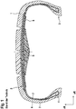
- Fig. 1 a cross-section through a car radial tire is shown, which has a profiled tread 1, side walls 2, bead areas 3, bead cores 4 as well as a multi-layer belt bandage 5 and a carcass insert 6.
- the tire On its inner surface, the tire is covered with an inner layer 7 made of an airtight rubber mixture.
- a sealant 8 is applied which is able to self-seal in the event of a puncture - damage to the tire.
- An internal absorber 9 adheres to the sealant 8 and is pressed onto the sealant 8 immediately after the application of the sealant 8, as long as it is still sufficiently tacky, as will be described below.
- the internal absorber 9 is sound-absorbing in terms of its Properties matched to the tire cavity frequency.
- the internal absorber 9 here has, for example, an approximately elongated triangular cross section which is symmetrical with respect to the tire equator.
- the foam of the internal absorber 9 is an open-cell foam, since it is best suited to absorb sound.
- Suitable sealants are, for example, polyurethane gels or viscous mixtures based on butyl rubbers, polybutenes or silicone, it being possible for the mixtures to contain the usual further constituents, such as plasticizer oils.
- the sealant is applied, for example by spraying, in such a way that it covers at least the inner surface opposite the tread 1.
- the tire can be set in rotation for optimal distribution of the sealant on the inner surface.
- the sealant is also introduced in such an amount that the layer thickness of the sealant is between 7 mm and 8 mm. At least immediately after application, the sealant should be relatively liquid and sticky. At this point in time, the prefabricated internal absorber 9 is introduced into the interior of the tire. After the reaction has ended, the internal absorber 9 adheres to the elastically deformable, but largely stationary sealant 8.
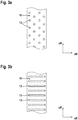
- the Fig. 2 shows a cross section through a pneumatic vehicle tire according to the invention.
- the pneumatic vehicle tire according to the invention differs from the tire of the prior art from FIG Fig. 1 in that a separating layer 10 is arranged between the sealing means 8 and the internal absorber 9.
- the separating layer 10 is designed in such a way that sufficient flowability of the sealant 8 for sealing and reliable adhesion of the internal absorber 9 is ensured.
- the separating layer 10 is, for example, a film or a fabric soaked in oil.
- the surface 11 of the separating layer facing the sealant has adhesion-reducing properties.
- the surface 12 of the separating layer facing the internal absorber has adhesive or non-adhesive properties.
- the separating layer 10 can have openings 13 (not shown here, cf. Fig. 3 ), by means of which the internal absorber 9 rests partially directly on the sealant.
- the passages 13 take up an area of 2% to 50% in relation to the base area of the internal absorber. In a plan view of the separating layer 10, the passages 13 are arranged distributed uniformly over the surface of the separating layer 10.
- the separating layer 10 has a thickness 14 of 0.05 to 2.0 mm.
- the internal absorber 9 has a thickness 15 of 20 mm to 40 mm.
- the separating layer 10 has a width 16 which corresponds approximately to the width 17 of the foam ring.
- the thickness 18 of the sealant layer 8 is between approximately 1.0 mm and 7.0 mm in those areas in which the separating layer 10 rests directly on the sealant 8.
- the sealant layer can have locally different layer thicknesses, in particular be contoured in the axial direction. A thickness of 3.5 mm in areas outside the internal absorber is particularly preferred.
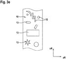
- FIG. 3a shows circular passages 13, the Figure 3b , 3c and 3d slot-like passages 13, which in the Figure 3b transversely to the longitudinal extent of the separating layer 10, in the Figure 3c parallel to the longitudinal extension of the separating layer 10 and in the Fig. 3d are arranged diagonally to the longitudinal extent of the separating layer 10.
- the Fig. 3e shows passages 13 of different geometries realized on one and the same separating layer 10.
- the passages 13 can be arranged regularly or irregularly and / or occur next to one another in different sizes.
- non-periodically recurring intervals are provided for example.
- 3c is not equidistant
Landscapes
- Engineering & Computer Science (AREA)
- Mechanical Engineering (AREA)
- Tires In General (AREA)
Description
- Die Erfindung betrifft einen Fahrzeugluftreifen mit einem in seinem Inneren an der dem Laufstreifen gegenüberliegenden Innenfläche haftend angebrachten schallabsorbierenden Innenabsorber, wobei der Innenabsorber an einem selbsttätig abdichtenden Dichtmittel haftet, welches zumindest unmittelbar nach seinem Aufbringen eine zum Anhaften erforderliche Klebrigkeit aufweist, wobei eine Trennschicht zwischen dem Dichtmittel und dem Innenabsorber angeordnet ist.
- Ein derartiger Fahrzeugluftreifen ist beispielsweise aus der
US 2010/307655 A1 bekannt. Die Trennschicht soll einerseits eine Akkumulation des Dichtmittels im mittigen Bereich unterhalb des Laufstreifens verhindern, sodass das Dichtmittel möglichst über die gesamte gewünschte Breite verbleibt, andererseits soll das Dichtmittel nicht in das Material des Schallabsorbers migrieren. Die Trennsicht ist beispielsweise ein Resin-Film, insbesondere aus einem thermoplastischen Elastomer. - Aus der
DE 10 2007 028 932 A1 ist ein Fahrzeugluftreifen mit einem in seinem Inneren an der dem Laufstreifen gegenüberliegenden Innenfläche haftend angebrachten schallabsorbierende, ringförmigen Innenabsorber bekannt, wobei der Innenabsorber an einem selbsttätig abdichtenden Dichtmittel haftet. Der Innenabsorber ist ein Ring aus offenzelligem Schaumstoff, welcher die Luftschwingung im Reifen reduziert und zu einer Verbesserung des Geräuschverhaltens im Fahrzeug führt. Das an der Reifeninnenseite aufgebrachte Dichtmittel hat zwei Funktionen: Es dichtet einen unerwünschten Durchstich des Reifens im Bereich des Laufstreifens ab, indem das viskose Dichtmittel im Falle einer Verletzung der Innenschicht in die Stelle der Verletzung fließt. Zudem dient das Dichtmittel gleichzeitig als "Haftmittel" zum Befestigen des schallabsorbierenden Schaumstoffringes. - Jedoch kann das Fließverhalten des Dichtmittels durch den auf dem Dichtmittel aufliegenden Innenabsorber nachteilig beeinflusst sein, so dass die erwünschte Dichtwirkung erst verspätet oder gar nicht eintritt. In Fällen, in denen der eindringende Fremdkörper aus dem Reifen wieder austritt und einen großen Luftkanal hinterlässt, ist eine zuverlässige Abdichtung durch das in seinem Fließverhalten nachteilig beeinflusste Dichtmittel besonders schwierig.
- Der Erfindung liegt die Aufgabe zu Grunde, die Abdichtung des Reifens bei Durchstichen zu verbessern. Ferner ist es die Aufgabe der Erfindung, ein Verfahren zur Herstellung eines vorgenannten Reifens bereitzustellen.
- Gelöst wird die gestellte Aufgabe in Bezug auf den Fahrzeugluftreifen erfindungsgemäß dadurch, dass die Trennschicht eine Folie ist, welche zumindest auf der dem Dichtmittel zugewandten Oberfläche haftungsvermindernde Eigenschaften aufweist.
- Erfindungsgemäß ist die Fließeigenschaft des Dichtmittels durch die zwischen dem Dichtmittel und dem Innenabsorber angeordnete Trennschicht positiv beeinflusst. Das Dichtmittel kann hierdurch zuverlässig abdichten.
- Der Innenabsorber besteht vorzugsweise aus offenzelligem Schaumstoff, alternativ aus Glaswolle, aus Kork oder aus Synthetikfasern (Fleece) oder aus einer Kombination von zwei oder mehr der vorgenannten Materialien.
- Der Innenabsorber ist vorzugsweise ein etwa ringkreisförmiges Bauteil, welches einstückig ausgeführt oder aus zwei oder mehr kreissegmentförmigen Einzelelementen zusammengesetzt ist.
- Die Trennschicht ist aus einem Stück oder aus sich überlappenden oder mit Abstand zueinander angeordneten Einzelsegmenten ausgeführt.
- Die Folie oder ihre Beschichtung besteht vorzugsweise auf Silikon- oder PTFE-(Fluorkohlenwasserstoffverbindungen, z.B. Perfluoroctansäure)-Basis oder aus Ölen bzw. verschiedenen Fettarten oder aus Papier (z.B. Pergamentpapier, Backpapier) oder Gewebe (aus Kunst- und/oder Naturfasern) .
- Silikon ist bei höheren Temperaturen einsetzbar, andere Materialien haben Kostenvorteile.
- Wirkprinzip ist die Versiegelung der Oberfläche und Reduzierung der Haftreibung,
- Vorteilhaft ist es, wenn die Trennschicht einseitig, vorzugsweise auf der dem Dichtmittel zugewandten Seite Antihaft-Eigenschaften aufweisen. Alternativ weist die Trennschicht beidseitig Antihaft-Eigenschaften auf.#
- In einer wiederum anderen Ausführung der Erfindung ist die Trennschicht ein flüssig aufgebrachtes Material, wie beispielsweise Farben und Lacke, Sprühfolien, Trennmittel (z.B. Formtrennmittel).
- In einer wiederum anderen Ausführung der Erfindung ist die Trennschicht aus organischem Material, z.B. Blatt eines Gummibaums.
- In einer wiederum anderen Ausführung der Erfindung weist die Oberfläche durch ihre Struktur Antihaft-Eigenschaften (Lotusblatt-Effekt) auf.
- Vorteilhaft ist es, wenn die Trennschicht Durchlässe aufweist, mittels derer der Innenabsorber partiell unmittelbar auf dem Haftmittel aufliegt und somit in unmittelbaren Haftkontakt mit dem Dichtmittel kommt. Es ist keine zusätzliche Haftbeschichtung auf der zum Innenabsorber weisenden Oberfläche der Trennschicht erforderlich.
- Hierbei ist es zweckmäßig , wenn die Durchlässe in Summe eine Fläche von 2 % bis 50 %, vorzugsweise eine Fläche von 5 bis 30 %, besonders bevorzugt eine Fläche von 10 bis 15 % in Bezug auf die Grundfläche des Innenabsorbers einnehmen. In einer besonderen Ausführungsform sind die die Durchlässe gleichmäßig über die Fläche der Trennschicht verteilt angeordnet. Die Grundfläche des Innenabsorbers ist die dem Reifen zugewandte Fläche. Der Einfluss des Innenabsorbers auf die Dichteigenschaften wird dadurch auf ein Minimum reduziert.
- Zweckmäßig ist es, wenn der Durchlass in Aufsicht auf die Trennschicht die Form eines Kreises, eines Ovals, und/oder eines länglichen Schlitzes, durchgängig oder durchbrochen aufweist, wobei die Schlitze in der Trennschicht längs, quer oder etwa diagonal angeordnet sind. Durch geeignete Dimensionierung der Durchlässe wird ausreichend fließfähiges Material für eine zuverlässige Abdichtung bereitgestellt und gleichzeitig eine ausreichende Klebkraft für den Schaum erzeugt.
- Zweckmäßig ist es, wenn die Trennschicht auf ihrer dem Innenabsorber zugewandten Oberfläche mit Hafteigenschaften ausgestattet ist., wobei diese Hafteigenschaften vorzugsweise durch eine geeignete Oberflächenbehandlung wie z.B. Gummierung der Trennschicht, dem Aufbringen eines weiteren Klebers, einer mechanischen Verbindung wie z.B. Klettband oder einer Kombination daraus erhalten ist.
- Der Kleber kann vorkonfektioniert mit der Trennschicht geliefert, aufgesprüht, aufgestrichen, als doppelseitiges Klebeband oder beispielsweise als reine Klebeschicht auf Trägermaterial appliziert werden.
- Zweckmäßig ist es, wenn die Trennschicht eine maximale Dicke von ≤ 2,0 mm, vorzugsweise eine Dicke (11) von 0,05 mm bis 0,5 mm aufweist. Die Dicke bemisst sich in radialer Richtung im an dem Reifen angeordneten Zustand.
- Vorteilhaft ist es, wenn der Innenabsorber eine radiale Dicke von ≥ 10 mm, vorzugsweise eine Dicke von 20 mm bis 40 mm aufweist.
- Die Trennschicht weist eine Breite auf, die gleich oder größer als die Breite der Dichtmittellage ist. Vorteil ist eine komplette Abdeckung der klebrigen Dichtmittellage.
- In einer alternativen Ausführungsform weist die Trennschicht eine Breite auf, die zwischen der Breite der Dichtmittellage und der Breite des Innenabsorbers liegt. Vorteil ist ein Ausgleich möglicher Material- und/oder Produktionstoleranzen.
- In einer weiteren alternativen Ausführungsform weist die Trennschicht eine Breite auf ,die etwa der Breite des Innenabsorbers entspricht. Vorteil ist eine Material- und damit Gewichtseinsparung.
- In wiederum einer weiteren alternativen Ausführungsform weist die Trennschicht eine geringere Breite als der Innenabsorber auf. Vorteil ist hierbei eine verbesserte Klebwirkung des Innenabsorbers auf dem Dichtmittel am Rand.
- Die Dichtmittellage kann in allen genannten Ausführungsformen breiter, schmaler oder gleich breit wie der Innenabsorber sein.
- Zweckmäßig ist es, wenn die Dicke der Dichtmittellage in denjenigen Bereichen, in denen die Trennschicht unmittelbar auf dem Dichtmittel aufliegt, 1 mm bis 5 mm, vorzugsweise eine Dicke von 1,5 mm bis 3,5 mm beträgt. Im Stand der Technik beträgt die Dicke des Dichtmittels etwa 7 mm. Durch die erfindungsgemäß stark verringerte Dicke des Dichtmittels sind Kostenvorteile erzielt.
- Zweckmäßig ist es, wenn die Dicke des Dichtmittels lokal unterschiedlich ist,wie beispielsweise im Bereich von Durchlässen dicker oder konturiert.
- Im Rahmen der Erfindung kommen sämtliche Dichtmittel in Frage, die selbsttätig abdichten und zumindest unmittelbar nach dem Aufbringen auf die innere Oberfläche des Reifens soweit klebrig sind, dass der Innenabsorber angepresst und derart haftend mit dem Dichtmittel verbunden werden kann. Es eignen sich daher beispielsweise Dichtmittel auf Basis von Polyurethan oder Dichtmittel, welche eineviskose Mischung auf Basis eines Butylkautschukes, eines Polybutens oder auf Basis von Silikon sind.
- Erfindungsgemäß kann die Trennschicht beispielsweise gemäß der nachfolgenden Tabelle ausgebildet sein:
Tabelle Variante Ausbildung Trennschicht dem Dichtmittel zugewandte Oberfläche dem Innenabsorber zugewandte Oberfläche 1 Ohne Durchlässe Nicht fließ verhindernd Haftende bzw. klebend 2 Mit Durchlässen Nicht fließ verhindernd Nicht klebend 3 Mit Durchlässen Nicht fließ verhindernd Haftend bzw. klebend - Gemäß dem Stand der Technik wird zunächst das Dichtmittel auf die Innenschicht aufgebracht und anschließend der Innenabsorber an das Dichtmittel im fertigen Reifen angehaftet.
- Gemäß dieser Erfindung wird die Trennschicht entweder vor dem Innenabsorber auf das Dichtmittel aufgebracht werden oder gemeinsam mit dem Innenabsorber appliziert oder wird der Innenabsorber mit Trennschicht und Dichtmittel vorkonfektioniert und als Bauteil in den Reifen eingebracht.
- Weitere Merkmale, Vorteile und Einzelheiten der Erfindung werden nun anhand der Zeichnungen, die neben einem Ausführungsbeispiel des Standes der Technik ein schematisches erfindungsgemäßes Ausführungsbeispiele darstellen, näher beschrieben. Dabei zeigen die:
-
Fig. 1 einen Querschnitt durch einen Fahrzeugluftreifen des Standes der Technik; -
Fig. 2 einen Querschnitt durch einen erfindungsgemäßen Fahrzeugluftreifen; -
Fig. 3a, 3b ,3c, 3d ,3e jeweils eine Aufsicht auf eine Trennschicht mit Durchlässen. - In
Fig. 1 ist ein Querschnitt durch einen PKW-Radialreifen dargestellt, welcher einen profilierten Laufstreifen 1, Seitenwände 2, Wulstbereiche 3, Wulstkerne 4 sowie einen mehrlagigen Gürtelverband 5 und eine Karkasseinlage 6 aufweist. An seiner inneren Fläche ist der Reifen mit einer Innenschicht 7 aus einer luftdicht ausgeführten Gummimischung bedeckt. An der dem Laufstreifen 1 gegenüberliegenden inneren Oberfläche der Innenschicht 7 ist ein Dichtmittel 8 aufgebracht, welches in der Lage ist, sich bei Durchstich - Beschädigung des Reifens - selbstabdichtend zu verhalten. Am Dichtmittel 8 haftet ein Innenabsorber 9, welcher unmittelbar nach dem Aufbringen des Dichtmittels 8, solange dieses noch ausreichend klebrig ist, auf das Dichtmittel 8 aufgepresst wird, wie nachfolgend beschrieben wird. Der Innenabsorber 9 ist bezüglich seiner schallabsorbierenden Eigenschaften auf die Reifenhohlraumfrequenz abgestimmt. Der Innenabsorber 9 weist beispielsweise hier einen etwa langgestreckt dreieckförmigen, bezüglich des Reifensäquators symmetrischen Querschnitt auf. Der Schaumstoff des Innenabsorber 9 ist ein offenzelliger Schaumstoff, da dieser am besten dazu geeignet ist, Schall zu absorbieren. Als Dichtmittel kommen beispielsweise Polyurethan-Gele oder viskose Mischungen auf Basis von Butylkautschuken, Polybutenen oder Silikon in Frage, wobei die Mischungen die üblichen weiteren Bestandteile, wie Weichmacheröle, enthalten können. Das Dichtmittel wird, beispielsweise durch Aufsprühen, derart eingebracht, dass es zumindest die dem Laufstreifen 1 gegenüberliegende innere Oberfläche bedeckt. Zur optimalen Verteilung des Dichtmittels an der Innenfläche kann der Reifen in Rotation versetzt werden. Das Dichtmittel wird ferner in einer solchen Menge eingebracht, dass die Schichtdicke des Dichtmittels zwischen 7 mm und 8 mm beträgt. Zumindest unmittelbar nach dem Aufbringen soll das Dichtmittel relativ flüssig und klebrig sein. Zu diesem Zeitpunkt wird der vorgefertigte Innenabsorber 9 in das Innere des Reifens eingebracht. Nach dem Ausreagieren haftet der Innenabsorber 9 an dem elastisch deformierbaren, aber weitestgehend ortsfest verbleibenden Dichtmittel 8. - Die
Fig. 2 zeigt einen Querschnitt durch einen erfindungsgemäßen Fahrzeugluftreifen. Der erfindungsgemäße Fahrzeugluftreifen unterscheidet sich von dem Reifen des Standes der Technik derFig. 1 darin, dass eine Trennschicht 10 zwischen dem Dichtmittel 8 und dem Innenabsorber 9 angeordnet ist. Die Trennschicht 10 ist derart beschaffen, dass eine zum Abdichten ausreichende Fließfähigkeit des Dichtmittels 8 sowie eine zuverlässige Haftung des Innenabsorber 9 gewährleistet ist. Die Trennschicht 10 ist beispielsweise eine Folie oder ein in Öl getränktes Gewebe. Die dem Dichtmittel zugewandte Oberfläche 11 der Trennschicht weist haftungsvermindernde Eigenschaften auf. Die dem Innenabsorber zugewandte Oberfläche 12 der Trennschicht hat haftende oder nicht haftende Eigenschaften. Um den Innenabsorber 9 dennoch sicher haftend anzuordnen, kann die Trennschicht 10 Durchlässe 13 (hier nicht dargestellt, vergl.Fig. 3 ) aufweisen, mittels derer der Innenabsorber 9 partiell unmittelbar auf dem Dichtmittel aufliegt. - Die Durchlässe 13 nehmen in Summe eine Fläche von 2% bis 50% in Bezug auf die Grundfläche des Innenabsorbers ein. Die Durchlässe 13 sind in Aufsicht auf die Trennschicht 10 gleichmäßig über die Fläche der Trennschicht 10 verteilt angeordnet.
- Die Trennschicht 10 weist eine Dicke 14 von 0,05 bis 2,0 mm auf. Der Innenabsorber 9 weist eine Dicke 15 von 20 mm bis 40 mm auf. Die Trennschicht 10 weist eine Breite 16 auf, die etwa der Breite 17 des Schaumstoffringes entspricht. Die Dicke 18 der Dichtmittellage 8 beträgt in denjenigen Bereichen, in denen die Trennschicht 10 unmittelbar auf dem Dichtmittel 8 aufliegt, zwischen etwa 1,0 mm und 7,0 mm. Die Dichtmittellage kann lokal unterschiedliche Schichtdicken aufweisen, insbesondere in axialer Richtung konturiert sein. Besonders bevorzugt ist eine Dicke von 3,5 mm in Bereichen außerhalb des Innenabsorbers.
- Die
Fig. 3a, 3b ,3c, 3d zeigen jeweils eine Aufsicht auf eine Trennschicht 10 mit Durchlässen 13. DieFig. 3a zeigt kreisförmige Durchlässe 13, dieFig. 3b ,3c und 3d schlitzartige Durchlässe 13, welche in derFig. 3b quer zur Längserstreckung der Trennschicht 10, in derFig. 3c parallel zur Längserstreckung der Trennschicht 10 und in derFig. 3d diagonal zur Längserstreckung der Trennschicht 10 angeordnet sind. DieFig. 3e zeigt Durchlässe 13 verschiedener Geometrien verwirklicht auf ein und derselben Trennschicht 10. Die Durchlässe 13 können regelmäßig oder unregelmäßig angeordnet sein und/oder in verschiedenen Größen nebeneinander auftreten. Bei 3b sind beispielhaft nicht periodisch wiederkehrende Abstände vorgesehen. Beispielhaft ist bei 3c nicht äquidistant -
- 1
- Laufstreifen
- 2
- Seitenwand
- 3
- Wulstbereich
- 4
- Wulstkern
- 5
- Gürtelverband
- 6
- Karkasseinlage
- 7
- Innenschicht
- 8
- Dichtmittellage
- 9
- Innenabsorber
- 10
- Trennschicht
- 11
- dem Dichtmittel zugewandte Oberfläche der Trennschicht
- 12
- dem Innenabsorber zugewandte Oberfläche der Trennschicht
- 13
- Durchlass
- 14
- Dicke der Trennschicht
- 15
- Dicke des Innenabsorbers
- 16
- Breite der Trennschicht
- 17
- Breite des Innenabsorbers
- 18
- Dicke der Dichtmittellage
- rR
- radiale Richtung
- aR
- axiale Richtung
- uR
- Umfangsrichtung
Claims (14)
- Fahrzeugluftreifen mit einem in seinem Inneren an der dem Laufstreifen (1) gegenüberliegenden Innenfläche (7) haftend angebrachten schallabsorbierenden Innenabsorber (9), wobei der Innenabsorber (9) an einem selbsttätig abdichtenden Dichtmittel (8) haftet, welches zumindest unmittelbar nach seinem Aufbringen eine zum Anhaften erforderliche Klebrigkeit aufweist, wobei eine Trennschicht (10) zwischen dem Dichtmittel (8) und dem Innenabsorber (9) angeordnet ist,
dadurch gekennzeichnet, dass die Trennschicht (10) derart beschaffen ist, dass eine zum Abdichten ausreichende Fließfähigkeit des Dichtmittels (8) sowie eine zuverlässige Haftung des Innenabsorbers (9) gewährleistet ist, und dass die Trennschicht (10) eine Folie ist, welche zumindest auf der dem Dichtmittel (8) zugewandten Oberfläche haftungsvermindernde Eigenschaften aufweist. - Fahrzeugluftreifen nach Anspruch 1, dadurch gekennzeichnet, dass die Trennschicht eine Sprühfolie ist.
- Fahrzeugluftreifen nach Anspruch 1 oder 2, dadurch gekennzeichnet, dass die Trennschicht (10) Durchlässe (13) aufweist, mittels derer, der Innenabsorber (9) partiell unmittelbar auf dem Dichtmittel (8) aufliegt und somit in unmittelbaren Haftkontakt mit dem Dichtmittel (8) kommt.
- Fahrzeugluftreifen nach Anspruch 3, dadurch gekennzeichnet, dass die Durchlässe (13) in Summe eine Fläche von 2 % bis 50 %, vorzugsweise eine Fläche von 5 bis 30%, besonders bevorzugt eine Fläche von 10 bis50% in Bezug auf die Grundfläche des Innenabsorbers (9) einnehmen.
- Fahrzeugluftreifen nach einem oder beiden der Ansprüche 3 und 4, dadurch gekennzeichnet, dass der Durchlass (13) in Aufsicht auf die Trennschicht (10) die Form eines Kreises, eines Ovals, eines länglichen Schlitzes und/oder eine beliebige Form, durchgängig oder durchbrochen aufweist, wobei die Schlitze in der Trennschicht längs, quer oder etwa diagonal angeordnet sind.
- Fahrzeugluftreifen nach einem oder mehreren der vorangehenden Ansprüche, dadurch gekennzeichnet, dass die Trennschicht (10) auf ihrer dem Innenabsorber zugewandten Oberfläche (12) mit Hafteigenschaften ausgestattet ist.
- Fahrzeugluftreifen nach einem oder mehreren der vorangehenden Ansprüche, dadurch gekennzeichnet, dass die Trennschicht (10) eine maximale Dicke (14) von ≤ 2.0 mm, vorzugsweise eine Dicke (14) von 0.05 mm bis 0.5 mm (bitte ergänzen) aufweist.
- Fahrzeugluftreifen nach einem oder mehreren der vorangehenden Ansprüche, dadurch gekennzeichnet, dass der Innenabsorber (9) eine Dicke (15) von ≥ 10 mm, vorzugsweise eine Dicke (15) von 20 mm bis 40 mm aufweist.
- Fahrzeugluftreifen nach einem oder mehreren der vorangehenden Ansprüche, dadurch gekennzeichnet, dass das Dichtmittel (8) ein Polyurethan-Gel ist.
- Fahrzeugluftreifen nach einem oder mehreren der vorangehenden Ansprüche 1 - 8, dadurch gekennzeichnet, dass das Dichtmittel (8) eine viskose Mischung auf Basis eines Butylkautschukes, eines Polybutens oder auf Basis von Silikon ist.
- Fahrzeugluftreifen nach einem oder mehreren der vorangehenden Ansprüche, dadurch gekennzeichnet, dass die Trennschicht (10) eine Breite (16) aufweist, die etwa der Breite (17) des Innenabsorbers (9) entspricht.
- Fahrzeugluftreifen nach einem oder mehreren der vorangehenden Ansprüche, dadurch gekennzeichnet, dass die Dicke (18) der Dichtmittellage (8) in denjenigen Bereichen, in denen die Trennschicht (10) unmittelbar auf dem Dichtmittel (8) aufliegt, 1 mm bis 5 mm, vorzugsweise eine Dicke von 1,5 mm bis 3,5 mm beträgt.
- Fahrzeugluftreifen nach einem oder mehreren der vorangehenden Ansprüche, dadurch gekennzeichnet, dass die Dicke (18) der Dichtmittellage (8) lokal unterschiedlich ist, vorzugsweise dass die Dicke (18) der Dichtmittellage (8) im Bereich der Durchlässe (10) unterschiedlich ist.
- Verfahren zur Herstellung eines Fahrzeugluftreifens gemäß einem oder mehrerer der vorangehenden Ansprüche, dadurch gekennzeichnet, dass man den Innenabsorber radial außen mit der Trennschicht belegt und dass man das Dichtmittel auf die Trennschicht aufbringt und anschließend am bereits vulkanisierten Reifen anordnet.
Applications Claiming Priority (3)
| Application Number | Priority Date | Filing Date | Title |
|---|---|---|---|
| DE102015200349 | 2015-01-13 | ||
| DE102015212105.4A DE102015212105A1 (de) | 2015-01-13 | 2015-06-30 | Fahrzeugluftreifen |
| PCT/EP2015/076279 WO2016113013A1 (de) | 2015-01-13 | 2015-11-11 | Fahrzeugluftreifen |
Publications (2)
| Publication Number | Publication Date |
|---|---|
| EP3245079A1 EP3245079A1 (de) | 2017-11-22 |
| EP3245079B1 true EP3245079B1 (de) | 2021-03-24 |
Family
ID=56233873
Family Applications (1)
| Application Number | Title | Priority Date | Filing Date |
|---|---|---|---|
| EP15795140.1A Active EP3245079B1 (de) | 2015-01-13 | 2015-11-11 | Fahrzeugluftreifen mit schallabsorbierendem mittel |
Country Status (6)
| Country | Link |
|---|---|
| US (1) | US10618359B2 (de) |
| EP (1) | EP3245079B1 (de) |
| JP (1) | JP6554171B2 (de) |
| CN (1) | CN107206852B (de) |
| DE (1) | DE102015212105A1 (de) |
| WO (1) | WO2016113013A1 (de) |
Families Citing this family (24)
| Publication number | Priority date | Publication date | Assignee | Title |
|---|---|---|---|---|
| US10507692B2 (en) * | 2014-10-06 | 2019-12-17 | Sumitomo Rubber Industries, Ltd. | Rubber compound for tires, pneumatic tire, and an airless tire |
| EP3515729B1 (de) * | 2016-09-23 | 2021-06-16 | Bridgestone Americas Tire Operations, LLC | Vorrichtungen zur reduzierung von reifengeräuschen |
| DE102016219666A1 (de) | 2016-10-11 | 2018-04-12 | Continental Reifen Deutschland Gmbh | Fahrzeugluftreifen und Verwendung eines Polybutens mit einem geringen Chlorgehalt |
| KR101938987B1 (ko) * | 2017-08-16 | 2019-01-15 | 한국타이어 주식회사 | 소음 저감 타이어 |
| EP3663102B1 (de) * | 2017-08-22 | 2024-06-19 | Sumitomo Rubber Industries, Ltd. | Luftreifen |
| GB201721970D0 (en) | 2017-12-27 | 2018-02-07 | Apollo Tyres Global R & D Bv | Noise reducing tyre |
| JP7089418B2 (ja) * | 2018-06-29 | 2022-06-22 | Toyo Tire株式会社 | 空気入りタイヤ |
| JP7089433B2 (ja) * | 2018-08-01 | 2022-06-22 | 住友ゴム工業株式会社 | 制音体付き空気入りタイヤ,及びその製造方法 |
| JP7136628B2 (ja) * | 2018-08-22 | 2022-09-13 | Toyo Tire株式会社 | 空気入りタイヤ |
| JP7205186B2 (ja) * | 2018-11-20 | 2023-01-17 | 住友ゴム工業株式会社 | 空気入りタイヤ |
| EP3894240B1 (de) * | 2018-12-12 | 2024-01-31 | Pirelli Tyre S.p.A. | Reifen mit einem geräuschreduzierenden element |
| JP2020093677A (ja) * | 2018-12-13 | 2020-06-18 | 株式会社ブリヂストン | 乗用車用空気入りラジアルタイヤ |
| KR102044888B1 (ko) * | 2019-04-12 | 2019-11-14 | 한국타이어앤테크놀로지 주식회사 | 공명 소음 저감 구조를 가진 공기입 타이어 |
| JP7441015B2 (ja) * | 2019-09-19 | 2024-02-29 | 株式会社ブリヂストン | 空気入りタイヤ |
| JP7348009B2 (ja) * | 2019-09-19 | 2023-09-20 | 株式会社ブリヂストン | 空気入りタイヤ |
| JP7248865B2 (ja) | 2019-10-10 | 2023-03-29 | ダウ シリコーンズ コーポレーション | セルフシーリングタイヤ |
| US12104020B2 (en) | 2019-10-10 | 2024-10-01 | Dow Silicones Corporation | Silicone-based products and their applications |
| WO2021068187A1 (en) | 2019-10-11 | 2021-04-15 | Dow Silicones Corporation | Silicone compositions and their applications |
| KR102084128B1 (ko) * | 2019-12-11 | 2020-03-03 | 한국타이어앤테크놀로지 주식회사 | 실란트 및 흡음재를 포함하는 타이어 |
| JP7669731B2 (ja) * | 2021-03-09 | 2025-04-30 | 住友ゴム工業株式会社 | 空気入りタイヤ |
| KR102581888B1 (ko) * | 2021-09-08 | 2023-09-25 | 금호타이어 주식회사 | 저소음 공기입 타이어 |
| KR102661522B1 (ko) * | 2021-09-27 | 2024-04-29 | 넥센타이어 주식회사 | 공기입 타이어 |
| CN115257246A (zh) * | 2022-06-20 | 2022-11-01 | 山东玲珑轮胎股份有限公司 | 一种兼顾低噪音和高安全特性的车辆轮胎及其制造方法 |
| TWI909069B (zh) * | 2022-07-12 | 2025-12-21 | 陳定福 | 預塗在密封劑前之中介質 |
Family Cites Families (7)
| Publication number | Priority date | Publication date | Assignee | Title |
|---|---|---|---|---|
| FR2431380A1 (fr) * | 1978-07-17 | 1980-02-15 | Michelin & Cie | Pneumatique avec revetement obturateur de crevaison |
| DE102007028932A1 (de) | 2007-06-22 | 2008-12-24 | Continental Aktiengesellschaft | Fahrzeugluftreifen |
| JP5267288B2 (ja) * | 2008-05-09 | 2013-08-21 | 横浜ゴム株式会社 | タイヤ騒音低減装置 |
| JP4862918B2 (ja) * | 2009-06-05 | 2012-01-25 | 横浜ゴム株式会社 | 空気入りタイヤ |
| US20110308706A1 (en) * | 2010-06-21 | 2011-12-22 | The Goodyear Tire & Rubber Company | Method for making pneumatic tire with foam noise damper |
| US20110308705A1 (en) * | 2010-06-21 | 2011-12-22 | Paul Harry Sandstrom | Method for making pneumatic tire with foam noise damper |
| US20130032262A1 (en) * | 2011-08-02 | 2013-02-07 | Bormann Rene Louis | Tire with foamed noise damper |
-
2015
- 2015-06-30 DE DE102015212105.4A patent/DE102015212105A1/de not_active Withdrawn
- 2015-11-11 US US15/528,521 patent/US10618359B2/en active Active
- 2015-11-11 CN CN201580073182.8A patent/CN107206852B/zh active Active
- 2015-11-11 WO PCT/EP2015/076279 patent/WO2016113013A1/de not_active Ceased
- 2015-11-11 EP EP15795140.1A patent/EP3245079B1/de active Active
- 2015-11-11 JP JP2017536559A patent/JP6554171B2/ja active Active
Non-Patent Citations (1)
| Title |
|---|
| None * |
Also Published As
| Publication number | Publication date |
|---|---|
| US10618359B2 (en) | 2020-04-14 |
| CN107206852A (zh) | 2017-09-26 |
| DE102015212105A1 (de) | 2016-07-14 |
| CN107206852B (zh) | 2019-11-12 |
| JP2018508401A (ja) | 2018-03-29 |
| US20180079263A1 (en) | 2018-03-22 |
| WO2016113013A1 (de) | 2016-07-21 |
| EP3245079A1 (de) | 2017-11-22 |
| JP6554171B2 (ja) | 2019-07-31 |
Similar Documents
| Publication | Publication Date | Title |
|---|---|---|
| EP3245079B1 (de) | Fahrzeugluftreifen mit schallabsorbierendem mittel | |
| EP3126161B1 (de) | Fahrzeugluftreifen | |
| EP3370982B1 (de) | Fahrzeugluftreifen | |
| EP2006125B1 (de) | Fahrzeugluftreifen | |
| DE102010029455B4 (de) | Luftreifen | |
| EP3317126B1 (de) | Fahrzeugluftreifen mit klebrigem dichtmittel | |
| EP3317127B1 (de) | Fahrzeugluftreifen mit schallabsorber | |
| DE102015210039A1 (de) | Fahrzeugluftreifen | |
| DE102013106015A1 (de) | Fahrzeugluftreifen | |
| WO1997008003A1 (de) | Kraftfahrzeug-dichtungsprofil | |
| DE19806935A1 (de) | Verfahren zum Herstellen eines Fahrzeugluftreifens mit einer an seiner Innenseele anhaftenden schallabsorbierenden Schaumstoffschicht sowie gemäß diesem Verfahren hergestellter Reifen | |
| EP3317128B1 (de) | Fahrzeugluftreifen mit schallabsorber | |
| DE102006038806B4 (de) | Verfahren zur Herstellung eines selbstdichtenden Fahrzeugluftreifens | |
| DE202018107177U1 (de) | Dichtband mit Trennschicht | |
| DE2927861C2 (de) | Luftreifen mit selbstabdichtender Innenauskleidung | |
| EP2825584A1 (de) | Epdm-wischgummi | |
| EP0140118B1 (de) | Verfahren zum Herstellen von Überzügen insbesondere für die Runderneuerung und Reparatur von Kraftfahrzeugen | |
| DE10242682B4 (de) | Rundfilterelement und Verfahren zu dessen Herstellung | |
| EP1375225A1 (de) | Klebeband zur Befestigung eines Dichtungselementes, und Verfahren zur Herstellung und zur Befestigung des Dichtungselementes | |
| EP0247469A1 (de) | Vulkanisationshülle zum Reparieren und Runderneuern von Fahrzeugreifen | |
| DE1024384B (de) | Schlauchloser Reifen, insbesondere fuer Kraftfahrzeuge | |
| DE102018123811A1 (de) | Verfahren zur Herstellung eines Schaumstoffdichtbandes und Schaumstoffdichtband | |
| DE10228614A1 (de) | Klebeband und Verfahren zur Herstellung und zur Befestigung eines Dichtungselements an einer Verwendungsstelle | |
| EP2148787B1 (de) | Dichtungsstrang, insbesondere zur abdichtung von klappen und türen an fahrzeugkarosserien | |
| DE10217129A1 (de) | Dichtungselement mit Dichtmasse sowie Verfahren zur Montage eines Dichtungselements mit Dichtmasse |
Legal Events
| Date | Code | Title | Description |
|---|---|---|---|
| STAA | Information on the status of an ep patent application or granted ep patent |
Free format text: STATUS: THE INTERNATIONAL PUBLICATION HAS BEEN MADE |
|
| PUAI | Public reference made under article 153(3) epc to a published international application that has entered the european phase |
Free format text: ORIGINAL CODE: 0009012 |
|
| STAA | Information on the status of an ep patent application or granted ep patent |
Free format text: STATUS: REQUEST FOR EXAMINATION WAS MADE |
|
| 17P | Request for examination filed |
Effective date: 20170814 |
|
| AK | Designated contracting states |
Kind code of ref document: A1 Designated state(s): AL AT BE BG CH CY CZ DE DK EE ES FI FR GB GR HR HU IE IS IT LI LT LU LV MC MK MT NL NO PL PT RO RS SE SI SK SM TR |
|
| AX | Request for extension of the european patent |
Extension state: BA ME |
|
| DAV | Request for validation of the european patent (deleted) | ||
| DAX | Request for extension of the european patent (deleted) | ||
| STAA | Information on the status of an ep patent application or granted ep patent |
Free format text: STATUS: EXAMINATION IS IN PROGRESS |
|
| 17Q | First examination report despatched |
Effective date: 20180615 |
|
| GRAP | Despatch of communication of intention to grant a patent |
Free format text: ORIGINAL CODE: EPIDOSNIGR1 |
|
| STAA | Information on the status of an ep patent application or granted ep patent |
Free format text: STATUS: GRANT OF PATENT IS INTENDED |
|
| RAP1 | Party data changed (applicant data changed or rights of an application transferred) |
Owner name: CONTINENTAL REIFEN DEUTSCHLAND GMBH |
|
| INTG | Intention to grant announced |
Effective date: 20201202 |
|
| GRAS | Grant fee paid |
Free format text: ORIGINAL CODE: EPIDOSNIGR3 |
|
| GRAA | (expected) grant |
Free format text: ORIGINAL CODE: 0009210 |
|
| STAA | Information on the status of an ep patent application or granted ep patent |
Free format text: STATUS: THE PATENT HAS BEEN GRANTED |
|
| AK | Designated contracting states |
Kind code of ref document: B1 Designated state(s): AL AT BE BG CH CY CZ DE DK EE ES FI FR GB GR HR HU IE IS IT LI LT LU LV MC MK MT NL NO PL PT RO RS SE SI SK SM TR |
|
| REG | Reference to a national code |
Ref country code: GB Ref legal event code: FG4D Free format text: NOT ENGLISH |
|
| REG | Reference to a national code |
Ref country code: CH Ref legal event code: EP |
|
| REG | Reference to a national code |
Ref country code: DE Ref legal event code: R096 Ref document number: 502015014444 Country of ref document: DE |
|
| REG | Reference to a national code |
Ref country code: IE Ref legal event code: FG4D Free format text: LANGUAGE OF EP DOCUMENT: GERMAN |
|
| REG | Reference to a national code |
Ref country code: AT Ref legal event code: REF Ref document number: 1374121 Country of ref document: AT Kind code of ref document: T Effective date: 20210415 |
|
| REG | Reference to a national code |
Ref country code: LT Ref legal event code: MG9D |
|
| PG25 | Lapsed in a contracting state [announced via postgrant information from national office to epo] |
Ref country code: NO Free format text: LAPSE BECAUSE OF FAILURE TO SUBMIT A TRANSLATION OF THE DESCRIPTION OR TO PAY THE FEE WITHIN THE PRESCRIBED TIME-LIMIT Effective date: 20210624 Ref country code: HR Free format text: LAPSE BECAUSE OF FAILURE TO SUBMIT A TRANSLATION OF THE DESCRIPTION OR TO PAY THE FEE WITHIN THE PRESCRIBED TIME-LIMIT Effective date: 20210324 Ref country code: FI Free format text: LAPSE BECAUSE OF FAILURE TO SUBMIT A TRANSLATION OF THE DESCRIPTION OR TO PAY THE FEE WITHIN THE PRESCRIBED TIME-LIMIT Effective date: 20210324 Ref country code: GR Free format text: LAPSE BECAUSE OF FAILURE TO SUBMIT A TRANSLATION OF THE DESCRIPTION OR TO PAY THE FEE WITHIN THE PRESCRIBED TIME-LIMIT Effective date: 20210625 Ref country code: BG Free format text: LAPSE BECAUSE OF FAILURE TO SUBMIT A TRANSLATION OF THE DESCRIPTION OR TO PAY THE FEE WITHIN THE PRESCRIBED TIME-LIMIT Effective date: 20210624 |
|
| PG25 | Lapsed in a contracting state [announced via postgrant information from national office to epo] |
Ref country code: RS Free format text: LAPSE BECAUSE OF FAILURE TO SUBMIT A TRANSLATION OF THE DESCRIPTION OR TO PAY THE FEE WITHIN THE PRESCRIBED TIME-LIMIT Effective date: 20210324 Ref country code: LV Free format text: LAPSE BECAUSE OF FAILURE TO SUBMIT A TRANSLATION OF THE DESCRIPTION OR TO PAY THE FEE WITHIN THE PRESCRIBED TIME-LIMIT Effective date: 20210324 Ref country code: SE Free format text: LAPSE BECAUSE OF FAILURE TO SUBMIT A TRANSLATION OF THE DESCRIPTION OR TO PAY THE FEE WITHIN THE PRESCRIBED TIME-LIMIT Effective date: 20210324 |
|
| REG | Reference to a national code |
Ref country code: NL Ref legal event code: MP Effective date: 20210324 |
|
| PG25 | Lapsed in a contracting state [announced via postgrant information from national office to epo] |
Ref country code: NL Free format text: LAPSE BECAUSE OF FAILURE TO SUBMIT A TRANSLATION OF THE DESCRIPTION OR TO PAY THE FEE WITHIN THE PRESCRIBED TIME-LIMIT Effective date: 20210324 |
|
| PG25 | Lapsed in a contracting state [announced via postgrant information from national office to epo] |
Ref country code: LT Free format text: LAPSE BECAUSE OF FAILURE TO SUBMIT A TRANSLATION OF THE DESCRIPTION OR TO PAY THE FEE WITHIN THE PRESCRIBED TIME-LIMIT Effective date: 20210324 Ref country code: CZ Free format text: LAPSE BECAUSE OF FAILURE TO SUBMIT A TRANSLATION OF THE DESCRIPTION OR TO PAY THE FEE WITHIN THE PRESCRIBED TIME-LIMIT Effective date: 20210324 Ref country code: EE Free format text: LAPSE BECAUSE OF FAILURE TO SUBMIT A TRANSLATION OF THE DESCRIPTION OR TO PAY THE FEE WITHIN THE PRESCRIBED TIME-LIMIT Effective date: 20210324 Ref country code: SM Free format text: LAPSE BECAUSE OF FAILURE TO SUBMIT A TRANSLATION OF THE DESCRIPTION OR TO PAY THE FEE WITHIN THE PRESCRIBED TIME-LIMIT Effective date: 20210324 |
|
| PG25 | Lapsed in a contracting state [announced via postgrant information from national office to epo] |
Ref country code: IS Free format text: LAPSE BECAUSE OF FAILURE TO SUBMIT A TRANSLATION OF THE DESCRIPTION OR TO PAY THE FEE WITHIN THE PRESCRIBED TIME-LIMIT Effective date: 20210724 Ref country code: SK Free format text: LAPSE BECAUSE OF FAILURE TO SUBMIT A TRANSLATION OF THE DESCRIPTION OR TO PAY THE FEE WITHIN THE PRESCRIBED TIME-LIMIT Effective date: 20210324 Ref country code: RO Free format text: LAPSE BECAUSE OF FAILURE TO SUBMIT A TRANSLATION OF THE DESCRIPTION OR TO PAY THE FEE WITHIN THE PRESCRIBED TIME-LIMIT Effective date: 20210324 Ref country code: PT Free format text: LAPSE BECAUSE OF FAILURE TO SUBMIT A TRANSLATION OF THE DESCRIPTION OR TO PAY THE FEE WITHIN THE PRESCRIBED TIME-LIMIT Effective date: 20210726 Ref country code: PL Free format text: LAPSE BECAUSE OF FAILURE TO SUBMIT A TRANSLATION OF THE DESCRIPTION OR TO PAY THE FEE WITHIN THE PRESCRIBED TIME-LIMIT Effective date: 20210324 |
|
| REG | Reference to a national code |
Ref country code: DE Ref legal event code: R097 Ref document number: 502015014444 Country of ref document: DE |
|
| PG25 | Lapsed in a contracting state [announced via postgrant information from national office to epo] |
Ref country code: DK Free format text: LAPSE BECAUSE OF FAILURE TO SUBMIT A TRANSLATION OF THE DESCRIPTION OR TO PAY THE FEE WITHIN THE PRESCRIBED TIME-LIMIT Effective date: 20210324 Ref country code: AL Free format text: LAPSE BECAUSE OF FAILURE TO SUBMIT A TRANSLATION OF THE DESCRIPTION OR TO PAY THE FEE WITHIN THE PRESCRIBED TIME-LIMIT Effective date: 20210324 Ref country code: ES Free format text: LAPSE BECAUSE OF FAILURE TO SUBMIT A TRANSLATION OF THE DESCRIPTION OR TO PAY THE FEE WITHIN THE PRESCRIBED TIME-LIMIT Effective date: 20210324 |
|
| PLBE | No opposition filed within time limit |
Free format text: ORIGINAL CODE: 0009261 |
|
| STAA | Information on the status of an ep patent application or granted ep patent |
Free format text: STATUS: NO OPPOSITION FILED WITHIN TIME LIMIT |
|
| PG25 | Lapsed in a contracting state [announced via postgrant information from national office to epo] |
Ref country code: SI Free format text: LAPSE BECAUSE OF FAILURE TO SUBMIT A TRANSLATION OF THE DESCRIPTION OR TO PAY THE FEE WITHIN THE PRESCRIBED TIME-LIMIT Effective date: 20210324 |
|
| 26N | No opposition filed |
Effective date: 20220104 |
|
| PG25 | Lapsed in a contracting state [announced via postgrant information from national office to epo] |
Ref country code: IS Free format text: LAPSE BECAUSE OF FAILURE TO SUBMIT A TRANSLATION OF THE DESCRIPTION OR TO PAY THE FEE WITHIN THE PRESCRIBED TIME-LIMIT Effective date: 20210724 |
|
| PG25 | Lapsed in a contracting state [announced via postgrant information from national office to epo] |
Ref country code: MC Free format text: LAPSE BECAUSE OF FAILURE TO SUBMIT A TRANSLATION OF THE DESCRIPTION OR TO PAY THE FEE WITHIN THE PRESCRIBED TIME-LIMIT Effective date: 20210324 |
|
| REG | Reference to a national code |
Ref country code: CH Ref legal event code: PL |
|
| PG25 | Lapsed in a contracting state [announced via postgrant information from national office to epo] |
Ref country code: LU Free format text: LAPSE BECAUSE OF NON-PAYMENT OF DUE FEES Effective date: 20211111 Ref country code: BE Free format text: LAPSE BECAUSE OF NON-PAYMENT OF DUE FEES Effective date: 20211130 |
|
| REG | Reference to a national code |
Ref country code: BE Ref legal event code: MM Effective date: 20211130 |
|
| PG25 | Lapsed in a contracting state [announced via postgrant information from national office to epo] |
Ref country code: IE Free format text: LAPSE BECAUSE OF NON-PAYMENT OF DUE FEES Effective date: 20211111 |
|
| REG | Reference to a national code |
Ref country code: AT Ref legal event code: MM01 Ref document number: 1374121 Country of ref document: AT Kind code of ref document: T Effective date: 20211111 |
|
| PG25 | Lapsed in a contracting state [announced via postgrant information from national office to epo] |
Ref country code: IT Free format text: LAPSE BECAUSE OF FAILURE TO SUBMIT A TRANSLATION OF THE DESCRIPTION OR TO PAY THE FEE WITHIN THE PRESCRIBED TIME-LIMIT Effective date: 20210324 Ref country code: AT Free format text: LAPSE BECAUSE OF NON-PAYMENT OF DUE FEES Effective date: 20211111 |
|
| PG25 | Lapsed in a contracting state [announced via postgrant information from national office to epo] |
Ref country code: HU Free format text: LAPSE BECAUSE OF FAILURE TO SUBMIT A TRANSLATION OF THE DESCRIPTION OR TO PAY THE FEE WITHIN THE PRESCRIBED TIME-LIMIT; INVALID AB INITIO Effective date: 20151111 |
|
| PG25 | Lapsed in a contracting state [announced via postgrant information from national office to epo] |
Ref country code: CY Free format text: LAPSE BECAUSE OF FAILURE TO SUBMIT A TRANSLATION OF THE DESCRIPTION OR TO PAY THE FEE WITHIN THE PRESCRIBED TIME-LIMIT Effective date: 20210324 |
|
| PG25 | Lapsed in a contracting state [announced via postgrant information from national office to epo] |
Ref country code: LI Free format text: LAPSE BECAUSE OF NON-PAYMENT OF DUE FEES Effective date: 20220630 Ref country code: CH Free format text: LAPSE BECAUSE OF NON-PAYMENT OF DUE FEES Effective date: 20220630 |
|
| PGFP | Annual fee paid to national office [announced via postgrant information from national office to epo] |
Ref country code: GB Payment date: 20231123 Year of fee payment: 9 |
|
| REG | Reference to a national code |
Ref country code: DE Ref legal event code: R081 Ref document number: 502015014444 Country of ref document: DE Owner name: CONTINENTAL REIFEN DEUTSCHLAND GMBH, DE Free format text: FORMER OWNER: CONTINENTAL REIFEN DEUTSCHLAND GMBH, 30165 HANNOVER, DE |
|
| PG25 | Lapsed in a contracting state [announced via postgrant information from national office to epo] |
Ref country code: MK Free format text: LAPSE BECAUSE OF FAILURE TO SUBMIT A TRANSLATION OF THE DESCRIPTION OR TO PAY THE FEE WITHIN THE PRESCRIBED TIME-LIMIT Effective date: 20210324 |
|
| PG25 | Lapsed in a contracting state [announced via postgrant information from national office to epo] |
Ref country code: TR Free format text: LAPSE BECAUSE OF FAILURE TO SUBMIT A TRANSLATION OF THE DESCRIPTION OR TO PAY THE FEE WITHIN THE PRESCRIBED TIME-LIMIT Effective date: 20210324 |
|
| PG25 | Lapsed in a contracting state [announced via postgrant information from national office to epo] |
Ref country code: MT Free format text: LAPSE BECAUSE OF FAILURE TO SUBMIT A TRANSLATION OF THE DESCRIPTION OR TO PAY THE FEE WITHIN THE PRESCRIBED TIME-LIMIT Effective date: 20210324 |
|
| GBPC | Gb: european patent ceased through non-payment of renewal fee |
Effective date: 20241111 |
|
| PG25 | Lapsed in a contracting state [announced via postgrant information from national office to epo] |
Ref country code: GB Free format text: LAPSE BECAUSE OF NON-PAYMENT OF DUE FEES Effective date: 20241111 |
|
| PGFP | Annual fee paid to national office [announced via postgrant information from national office to epo] |
Ref country code: DE Payment date: 20251130 Year of fee payment: 11 |
|
| PGFP | Annual fee paid to national office [announced via postgrant information from national office to epo] |
Ref country code: FR Payment date: 20251126 Year of fee payment: 11 |