EP3245375B1 - Joint pour une porte sans seuil - Google Patents
Joint pour une porte sans seuil Download PDFInfo
- Publication number
- EP3245375B1 EP3245375B1 EP16700045.4A EP16700045A EP3245375B1 EP 3245375 B1 EP3245375 B1 EP 3245375B1 EP 16700045 A EP16700045 A EP 16700045A EP 3245375 B1 EP3245375 B1 EP 3245375B1
- Authority
- EP
- European Patent Office
- Prior art keywords
- seal
- sealing
- leg
- strip
- legs
- Prior art date
- Legal status (The legal status is an assumption and is not a legal conclusion. Google has not performed a legal analysis and makes no representation as to the accuracy of the status listed.)
- Active
Links
Images


Classifications
-
- E—FIXED CONSTRUCTIONS
- E06—DOORS, WINDOWS, SHUTTERS, OR ROLLER BLINDS IN GENERAL; LADDERS
- E06B—FIXED OR MOVABLE CLOSURES FOR OPENINGS IN BUILDINGS, VEHICLES, FENCES OR LIKE ENCLOSURES IN GENERAL, e.g. DOORS, WINDOWS, BLINDS, GATES
- E06B7/00—Special arrangements or measures in connection with doors or windows
- E06B7/16—Sealing arrangements on wings or parts co-operating with the wings
- E06B7/22—Sealing arrangements on wings or parts co-operating with the wings by means of elastic edgings, e.g. elastic rubber tubes; by means of resilient edgings, e.g. felt or plush strips, resilient metal strips
- E06B7/23—Plastic, sponge rubber, or like strips or tubes
- E06B7/2316—Plastic, sponge rubber, or like strips or tubes used as a seal between the floor and the wing
-
- E—FIXED CONSTRUCTIONS
- E06—DOORS, WINDOWS, SHUTTERS, OR ROLLER BLINDS IN GENERAL; LADDERS
- E06B—FIXED OR MOVABLE CLOSURES FOR OPENINGS IN BUILDINGS, VEHICLES, FENCES OR LIKE ENCLOSURES IN GENERAL, e.g. DOORS, WINDOWS, BLINDS, GATES
- E06B7/00—Special arrangements or measures in connection with doors or windows
- E06B7/16—Sealing arrangements on wings or parts co-operating with the wings
- E06B7/18—Sealing arrangements on wings or parts co-operating with the wings by means of movable edgings, e.g. draught sealings additionally used for bolting, e.g. by spring force or with operating lever
- E06B7/20—Sealing arrangements on wings or parts co-operating with the wings by means of movable edgings, e.g. draught sealings additionally used for bolting, e.g. by spring force or with operating lever automatically withdrawn when the wing is opened, e.g. by means of magnetic attraction, a pin or an inclined surface, especially for sills
- E06B7/21—Sealing arrangements on wings or parts co-operating with the wings by means of movable edgings, e.g. draught sealings additionally used for bolting, e.g. by spring force or with operating lever automatically withdrawn when the wing is opened, e.g. by means of magnetic attraction, a pin or an inclined surface, especially for sills with sealing strip movable in plane of wing
-
- E—FIXED CONSTRUCTIONS
- E06—DOORS, WINDOWS, SHUTTERS, OR ROLLER BLINDS IN GENERAL; LADDERS
- E06B—FIXED OR MOVABLE CLOSURES FOR OPENINGS IN BUILDINGS, VEHICLES, FENCES OR LIKE ENCLOSURES IN GENERAL, e.g. DOORS, WINDOWS, BLINDS, GATES
- E06B7/00—Special arrangements or measures in connection with doors or windows
- E06B7/16—Sealing arrangements on wings or parts co-operating with the wings
- E06B7/18—Sealing arrangements on wings or parts co-operating with the wings by means of movable edgings, e.g. draught sealings additionally used for bolting, e.g. by spring force or with operating lever
-
- E—FIXED CONSTRUCTIONS
- E06—DOORS, WINDOWS, SHUTTERS, OR ROLLER BLINDS IN GENERAL; LADDERS
- E06B—FIXED OR MOVABLE CLOSURES FOR OPENINGS IN BUILDINGS, VEHICLES, FENCES OR LIKE ENCLOSURES IN GENERAL, e.g. DOORS, WINDOWS, BLINDS, GATES
- E06B7/00—Special arrangements or measures in connection with doors or windows
- E06B7/16—Sealing arrangements on wings or parts co-operating with the wings
- E06B7/22—Sealing arrangements on wings or parts co-operating with the wings by means of elastic edgings, e.g. elastic rubber tubes; by means of resilient edgings, e.g. felt or plush strips, resilient metal strips
- E06B7/23—Plastic, sponge rubber, or like strips or tubes
- E06B7/2301—Plastic, sponge rubber, or like strips or tubes without an integrally formed part for fixing the edging
- E06B7/2303—Plastic, sponge rubber, or like strips or tubes without an integrally formed part for fixing the edging hollow
Definitions
- the present invention relates to a seal for a sillless door.
- Door seals for sealing a lower end face of a threshold-free door are known. They should prevent light transmission and also offer soundproofing. Depending on the embodiment, an air passage should also be avoided.
- EP 0 338 974 discloses a lowerable door seal with a U-shaped housing rail and a sealing strip with a support profile and a U-shaped elastomeric sealing profile.
- the sealing strip can be automatically raised and lowered in the housing rail, the movement taking place relative to the housing rail.
- the sealing profile has two legs and a curved sealing web connecting these two legs, which rests sealingly on the floor in the lowered state of the sealing strip.
- the sealing profile is attached to the carrier rail on both sides. This seal has proven itself in practice.
- EP 2 554 774 discloses a similar seal, the fastening of the sealing profile on both sides on the support rail being carried out at different heights.
- EP 0 841 457 describes a V-shaped sealing profile of a lowerable door seal, which has two downwardly directed feet and inwardly directed abutments into a cavity on which the carrier profile rests.
- EP 1 233 137 proposes various means for improving the sound insulation, some of which are arranged on the insides of the legs and protrude into a cavity formed by the two legs and the sealing web of the sealing profile.
- the seal according to the invention for a threshold-free door for sealing a gap between a door leaf and a floor has a support rail and a sealing profile held on the support rail.
- the sealing profile has an essentially U-shaped cross section with two legs and a sealing web connecting the two legs to one another for sealing support on the floor.
- at least two strips have a thickness which is greater than the thickness of the adjacent region of the leg.
- the thickness of the strip is to be understood here as the extension parallel to the transverse central axis. The thickness is thus the height of the strip.
- the length of the strip is the dimension transverse to the transverse central axis and transverse to the longitudinal central axis of the seal.
- the Thickness of the leg is the wall thickness of the leg and is thus the extent which runs at an angle to the transverse central axis and transversely to the longitudinal central axis of the seal.
- These thicker strips are located on each of the legs. They are preferably located approximately at the same height as the legs. These strips are preferably approximately twice as thick or more than twice as thick as the adjacent region of the leg to which they are attached. The two legs are preferably of the same thickness.
- the at least one strip preferably extends over the entire length of the sealing profile, wherein it preferably has no interruptions. It preferably has the same cross section over the entire length of the sealing profile.
- this shape shows very good sound insulation values on the test stand, which differ significantly from the seals used up to now. This is particularly the case when the seal is an automatic lowering seal with a known spring-loaded lowering mechanism.
- Typical measured sound insulation values are 54 to 56 dB compared to 46 to 50 dB of the known seals. Doors with simple seals usually have sound insulation values of around 27 dB.
- the sound insulation values of brick walls are typically around 55 dB. The higher the measured value, the better the sound insulation.
- At least one of the strips preferably runs at a distance from the underside of the carrier rail. All strips preferably run at a distance from this underside. This refers to the raised or unloaded condition of the seal. If the seal is lowered or if it rests on the floor in a sealing manner, the sealing profile is usually out of symmetry in the lateral direction with respect to the support rail shifted along the longitudinal central axis. In this displaced state, one strip can usually rest on the underside of the carrier rail, the distance between the other strip and the underside having been increased.
- two of the at least two strips are arranged in the upper region of the cavity, i.e. adjacent to the underside of the support rail. They are preferably located at least in the upper half of the cavity.
- each leg Preferably, exactly one strip is arranged on each leg.
- the strip can be arranged in a connection area of the sealing web. In a preferred embodiment, however, it is located at a distance from the connection area of the sealing web.
- strips which are arranged on different legs are arranged mirror-symmetrically to one another along a transverse central axis of the seal, wherein they are formed mirror-symmetrically to one another along this transverse central axis.
- the entire sealing profile or the entire sealing strip including the carrier profile or the entire seal is preferably designed mirror-symmetrically to the transverse central axis.
- the sealing profile can also be designed offset in height, as shown in FIG EP 2 554 774 the case is. The offset can only relate to the fastening of the sealing profile to the support rail and / or it can relate to the arrangement of the strips. The offset arrangement of individual parts enables an optimally narrow design of the seal.
- At least one of the strips ends at a distance from the transverse central axis of the seal.
- all of the strips on the legs end at a distance from one another.
- the sealing web is made thinner than a to the strips of adjacent areas of the legs.
- Optimized sound insulation values are achieved if the at least one strip extends at an angle of 80 ° - 100 ° to the transverse center axis of the seal.
- a further optimization of the sound insulation values is achieved in that at least one of the
- the strip has a substantially rectangular cross-section, one side of the rectangle being bent in the shape of a part of a circle and this side forming a free end of the strip protruding into the cavity.
- At least one of the strips can be hollow or solid. Massive is to be understood here in the sense of "filled in”.
- the sealing web is preferably free of projections or ribs on its outside, which are directed downwards towards the floor.
- the sealing web is preferably designed to be curved in order to again optimize the deformation, to increase the contact surface and thus to optimize the soundproofing.
- the two legs each merge with a tapering step into the sealing web.
- the transition area tapers continuously.
- the legs it is possible for the legs to taper again in the area facing away from the sealing web, with the tapering here also being able to take place in a stepped or stepless manner.
- only the at least one strip is located in the cavity. In preferred embodiments there are only two strips, which are each arranged on a leg, in the cavity.
- At least one space dividing element projecting inward into the cavity is arranged on the sealing web.
- the space dividing element is preferably at least one upwardly projecting rib, which preferably is made thinner than the at least one strip.
- the space dividing element is an angled web with two ends and with two angles, both ends being arranged on the sealing web at a distance from one another. These room dividing elements also improve the sound insulation. Depending on the embodiment, they contact the strips when the seal is lowered or sealingly resting on the floor, or they contact one another. In other exemplary embodiments, in this state too, they run at a distance from one another and / or at a distance from the strips.
- the elastomer sealing profile is preferably formed in one piece. In its basic form, it preferably corresponds to the tried and tested profile EP 0 338 974 . It preferably has an essentially U-shaped cross section, with the two legs, preferably of equal length, and the sealing web connecting the two legs.
- the sealing web is preferably designed to be curved.
- the two legs are directed upwards and preferably each have a free end. The legs, preferably their free ends, slide against the inside of the housing rail.
- the seal can be a sliding seal.
- the seal further comprises a housing rail in which the support rail and the sealing profile are held, which together form a sealing strip.
- the seal is a manually lowerable and liftable seal, and more preferably it is a mechanically automatically lowerable and liftable seal.
- the sealing strip is held in the housing rail so that it can be lowered and raised relative to the housing rail.
- the actuating mechanism is preferably of a known type, in particular can be activated on one side. In particular, it is spring-loaded.
- the exemplary embodiments described here are automatically operated drop-down seals.
- the actuation or lowering mechanism is not shown. However, it is well known in the art.
- the seal has a U-shaped housing rail 1 which is open at the bottom and in which a sealing strip 2, 3 is arranged.
- the sealing strip has a carrier rail 2 and an elastomeric sealing profile 3 attached to it.
- the housing rail 1 and the support rail 2 are preferably made of aluminum.
- the sealing profile 3 is preferably made of silicone or rubber.
- the housing rail 1 has two side walls 10 which run parallel to one another and which are connected to one another via an upper web 11. Adjacent to the upper web 11, there is an inwardly protruding projection 12 on the inside of both side walls 10, which extends parallel to the upper web 10, preferably over the entire length of the housing rail 1. In the groove 13 formed between the upper web 10 and the projections 12, a slide or force transmission rod (not shown) is held, which transmits an external triggering force acting on an actuating rod to leaf springs of the lowering mechanism.
- These items are, for example, off EP 0 509 961 and DE 19 516 530 well known and not shown here.
- the carrier rail 2 has a fastening body 21 with two laterally arranged receiving grooves 22.
- the receiving grooves 22 are designed to be open to the side and are undercut. They or at least their receiving openings preferably incline slightly downwards towards the open end of the housing rail 1. In other words, the receiving openings are inclined towards a transverse central axis Q of the seal, this angle being relatively small.
- the fastening body 21 has an underside 23 which is preferably flat. In other words, it has no projections or depressions.
- the bottom 23 is preferably designed to be slightly inclined towards the transverse central axis Q of the seal, whereby it inclines downwards towards the outside.
- two side walls 20 extend upward from the fastening body 21.
- the two side walls 20 form an upwardly open U-shaped groove in which the lowering mechanism can extend.
- the sealing profile 3 is U-shaped. It has two legs 30 and a sealing web 32 connecting these legs 30.
- the two legs 30 are designed to end freely at the top. When the seal is lowered, they slide against the insides of the side walls 10 of the housing rail 1 and seal laterally in the lowered state, as shown in FIG Figure 2 is easily recognizable.
- the legs 30 are preferably not connected to the support rail 2 at their free end.
- the legs 30 can run in a straight line or, as shown here, have a slight kink.
- a lateral spreading rib 38 is integrally formed on the inside of the leg, here in the area of the bend.
- the sealing web 32 is curved. It is thinner than the adjoining area of the legs 30.
- the transition between the leg 30 and the sealing web 32 is formed in this example by a step 33. Is how in Figure 8 If there is no step, the transition between the leg and the sealing web is to be found where, at least in the sealing state of the seal resting on the floor, the essentially horizontal area of the sealing profile in the essentially vertical or vertical portion of the sealing profile transforms. This definition applies to all exemplary embodiments in which the sealing web has a thickness which is essentially the same as the thickness of the adjacent region of the legs.
- the transition in the variant according to Figure 9 is formed by a notch or taper 39 of the sealing profile 3 between the leg 30 and the sealing web 32.
- the legs 30 have the same thickness over their entire length.
- the sealing web 32 is also of the same thickness over its entire length.
- a fastening rib 31 is formed on the inside of each leg 30.
- it has a structure similar to that of a fir tree.
- This fastening rib 31 engages in the undercut receiving groove 22 facing it, as a result of which the sealing profile 3 is fastened to the carrier profile 2 on both sides.
- the carrier profile 2 and the sealing profile 3 can thus be lowered and raised together relative to the housing rail 1.
- At least one of the two legs 30 has at least one strip 34 below the fastening ribs 31 and at a distance from them.
- a strip 34 is formed on each leg 30. It is preferably formed in one piece with the rest of the sealing profile. It is preferably made of the same material as the rest of the sealing profile. Both strips 34 are preferably at the same height and are thus opposite one another.
- the entire sealing profile 3 is preferably made of the same material and does not have any zones of different density.
- at least the area of the sealing profile 3 adjacent to the strip 34 is made from the same material and with the same density.
- the strip can also be glued or welded on. However, the one-piece and unitary embodiment of the sealing profile is clearly preferred.
- the strips 34 are located below the underside 23 of the support rail 2, but at a distance from it. This applies to the unloaded state, when the sealing bend does not lie tightly on the floor. If it rests in a sealing manner, one of the strips 34 touches the support rail and the other strip is further spaced from the support rail than before. This takes place due to the grinding movement of the sealing profile when the support rail is lowered while the door is being closed.
- the strip 34 is also at a distance from the step 33, which leads to the sealing web 32.
- the strips 34 are preferably significantly thicker than the area of the legs 30 adjacent to them and preferably significantly thicker than the sealing web 32. Preferably, the strips 34 are at least twice as thick or many times thicker than the sealing web 32.
- the thickness of the strips 34 (in Figure 2 the height) is preferably 3 to 5 mm, with a typical thickness of the sealing web 32 of 0.5 to 1.5 mm.
- the length of the strips 34 (in Figure 2 the horizontal extent in the plane of the drawing sheet is preferably 4 to 6 mm.
- the strips 34 preferably extend into the cavity 37 in a direction perpendicular to the longitudinal direction of the legs 30. They preferably do not extend as far as the transverse central axis Q of the seal, but rather end beforehand. As a result, the two opposite strips 34 do not touch.
- the two opposite strips 34 are preferably designed identically, as shown here, and are arranged mirror-symmetrically to one another. They are massive, i.e. filled in, trained.
- Each strip 34 has a substantially rectangular cross section with a free rounded end 341.
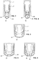
- FIGS 8 and 9 are variants of the sealing profile according to Figure 1 shown.
- the fastening ribs 31 are shown in dashed lines. This is to show that these and the other variants can have a different shape.
- the housing rail 1 is shaped differently in order to enable a different type of fastening of the lowering mechanism and a reduction in the overall height of the seal.
- the sealing profile 3 is designed similarly to the first exemplary embodiment, with the limbs 30 in the region of the strips 34 being made thicker than at the free end of the limbs.
- the free end of the legs has a similar thickness to the sealing web 32.
- the strips 34 are arranged in the transition regions between the legs 30 and the sealing web 32. There is no separate step 33.
- the two strips 34 are of the same length as in the first example according to FIG Figures 1 and 2 . Since the seal is made wider, however, they do not protrude almost to the middle of the cavity 37 or almost to the transverse central axis Q, as in the first example. In this example, they end approximately halfway to the transverse central axis Q or earlier.
- the strips 34 are hollow.
- the corresponding cavity 340 is preferably filled with air.
- a space dividing element in the form of a rib 36 which is formed centrally on the inside of the sealing web 32 and protrudes upward into the cavity 37.
- This rib 36 preferably ends at a distance from the strips 34.
- This rib 36 preferably touches the strips 34 when it is lowered and resting on the floor. This allows individual at least approximately closed chambers to be formed in the cavity. This increases the sound insulation.
- the rib 36 is preferably straight and it is preferably at least as thick as the sealing web 32. Its thickness preferably corresponds approximately to the thickness of the legs 30.
- the rib 36 is preferably made so thick that it can protrude upward on its own.
- the rib 36 can be formed in one piece with the rest of the sealing profile and preferably consist of the same material without stiffening means. However, it can also be made of a different material or stiffened and / or glued, welded or otherwise connected to the sealing web 32.
- ribs 36 which are arranged at a distance from one another on the sealing web 32.
- they are designed to be the same length. However, they can also be of different lengths.
- none of the three ribs makes contact with the strips 34. In this example, however, they protrude into the intermediate area defined by the two strips 34.
- two, four or more ribs 36 are present.
- a web 35 is arranged on the sealing web 32, with both ends being fastened or molded onto the sealing web 23.
- the web 35 preferably has three legs which are at an angle to one another. Together with the sealing web 32, they form a trapezoid with a rounded side.
- the web 35 also preferably does not contact the strips 34.
- Figure 7 shows a variant with a narrow seal, relatively short strips 34, which only extend approximately half the way to the transverse central axis Q, and with a web 35.
- sealing profiles according to Figures 1 to 7 can also be combined with each other to create new variants.
- sealing webs 32 with and without space dividing elements can be combined with hollow strips 34 or the shape of the legs 30 and / or the fastening ribs 31 can be changed.
- the seal according to the invention has surprisingly good sound insulation.
- REFERENCE LIST 1 Housing rail 30th leg 10 Side wall of the housing rail 31 Fastening rib 11 upper bridge 32 Sealing bar 12th head Start 33 step 13th Groove 34 Stripes 340 cavity 2 Support rail 341 free end 20th Side wall of the support rail 35 web 36 rib 21 Fastening body 37 cavity 22nd Receiving groove 38 lateral splay rib 23 bottom 39 rejuvenation 3 Sealing profile Q Transverse central axis
Landscapes
- Engineering & Computer Science (AREA)
- Civil Engineering (AREA)
- Structural Engineering (AREA)
- Specific Sealing Or Ventilating Devices For Doors And Windows (AREA)
- Seal Device For Vehicle (AREA)
Claims (17)
- Joint d'étanchéité pour une porte sans seuil, servant à rendre étanche un interstice entre un battant de porte et un sol, le joint d'étanchéité comprenant un rail porteur (2) et un profilé d'étanchéité (3) retenu sur le rail porteur (2), le profilé d'étanchéité (3) présentant une section transversale substantiellement en forme de U dotée d'une première et d'une deuxième branche (30) et d'un élément jointif d'étanchéité (32) reliant l'une à l'autre la première et la deuxième branche (30) et destiné à s'appuyer de manière étanche sur le sol, une cavité (37) étant prévue, laquelle est définie par un côté inférieur (23) du rail porteur (2), la première et la deuxième branche (30) et l'élément jointif d'étanchéité (32), et le profilé d'étanchéité (3), pour l'amélioration de l'isolation acoustique, comportant, sur la première branche (30), au moins une première bande (34) disposée sur un côté intérieur de la première branche (30) et pénétrant dans la cavité et, sur la deuxième branche (30), au moins une deuxième bande (34) disposée sur un côté intérieur de la deuxième branche (30) et pénétrant dans la cavité,
au moins une parmi l'au moins une première bande (34) présentant une épaisseur qui est supérieure à l'épaisseur de la région adjacente de la première branche (30), et au moins une de l'au moins une deuxième bande (34) présentant une épaisseur qui est supérieure à l'épaisseur de la région adjacente de la deuxième branche (30),
caractérisé en ce
qu'au moins une des première et deuxième bandes (34) qui présentent la plus grande épaisseur, présentent une section transversale substantiellement rectangulaire, un côté du rectangle étant réalisé de manière courbée en forme de partie de cercle, et ce côté formant une extrémité libre (341) de la bande (34), laquelle extrémité pénètre dans la cavité. - Joint d'étanchéité selon la revendication 1, l'au moins une bande (34) qui présente la section transversale substantiellement rectangulaire s'étendant de manière espacée du côté inférieur (23) du rail porteur (2).
- Joint d'étanchéité selon l'une des revendications 1 et 2, les bandes (34) qui sont disposées sur différentes branches (30) étant disposées en symétrie miroir les unes par rapport aux autres le long d'un axe médian transversal (Q) du joint d'étanchéité, ces branches étant réalisées en symétrie miroir les unes par rapport aux autres le long de cet axe médian transversal (Q).
- Joint d'étanchéité selon l'une des revendications 1 à 3, l'au moins une bande (34) qui présente la section transversale substantiellement rectangulaire se terminant de manière espacée de l'axe médian transversal (Q) du joint d'étanchéité.
- Joint d'étanchéité selon l'une des revendications 1 à 4, toutes les bandes (34) disposées sur des branches (30) se terminant de manière espacée les unes des autres.
- Joint d'étanchéité selon l'une des revendications 1 à 5, l'élément jointif d'étanchéité (32) étant réalisé de manière plus mince qu'une région des branches (30) adjacente aux bandes (34) présentant une plus grande épaisseur.
- Joint d'étanchéité selon l'une des revendications 1 à 6, l'au moins une bande (34) qui présente la section transversale substantiellement rectangulaire étant réalisée de manière creuse ou pleine.
- Joint d'étanchéité selon l'une des revendications 1 à 7, l'élément jointif d'étanchéité (32) étant, sur son côté extérieur, dépourvu de saillies ou de nervures orientées vers le bas en direction du sol.
- Joint d'étanchéité selon l'une des revendications 1 à 8, l'élément jointif d'étanchéité (32) étant réalisé de manière courbée.
- Joint d'étanchéité selon l'une des revendications 1 à 9, les deux branches (30) se prolongeant dans l'élément jointif d'étanchéité (32) respectivement par un gradin (33) se rétrécissant.
- Joint d'étanchéité selon l'une des revendications 1 à 10, au moins un élément de division spatiale (35, 36) faisant saillie vers l'intérieur dans la cavité (37) étant disposé sur l'élément jointif d'étanchéité (32).
- Joint d'étanchéité selon la revendication 11, l'élément de division spatiale étant au moins une nervure (36) faisant saillie vers le haut.
- Joint d'étanchéité selon la revendication 11, l'élément de division spatiale étant un élément jointif coudé (35) présentant deux extrémités et présentant deux angles, les deux extrémités étant disposées de manière espacée l'une de l'autre sur l'élément jointif d'étanchéité (32).
- Joint d'étanchéité selon l'une des revendications 1 à 13, le joint d'étanchéité comportant en outre un rail de boîtier (1), le rail porteur (2) et le profilé d'étanchéité (3) formant une baguette d'étanchéité, et cette baguette d'étanchéité étant retenue dans le rail de boîtier (1) de manière à pouvoir être abaissée et élevée par rapport au rail de boîtier (1).
- Joint d'étanchéité selon l'une des revendications 1 à 14, la première ou deuxième bande (34) qui présente une section transversale substantiellement rectangulaire s'étendant suivant un angle de 80° à 100° par rapport à l'axe médian transversal du joint d'étanchéité.
- Joint d'étanchéité selon l'une des revendications 1 à 15, l'au moins une première et deuxième bande (34) qui présente une plus grande épaisseur étant au moins deux fois plus épaisse que la région adjacente de la branche (30).
- Joint d'étanchéité selon l'une des revendications 1 à 16, la première branche (30), la deuxième branche (30) et l'élément jointif d'étanchéité (32) définissant une forme extérieure du profilé d'étanchéité en forme de U.
Applications Claiming Priority (2)
| Application Number | Priority Date | Filing Date | Title |
|---|---|---|---|
| EP15151330 | 2015-01-15 | ||
| PCT/EP2016/050072 WO2016113149A1 (fr) | 2015-01-15 | 2016-01-05 | Élément d'étanchéité pour porte sans seuil |
Publications (2)
| Publication Number | Publication Date |
|---|---|
| EP3245375A1 EP3245375A1 (fr) | 2017-11-22 |
| EP3245375B1 true EP3245375B1 (fr) | 2021-05-19 |
Family
ID=52358643
Family Applications (1)
| Application Number | Title | Priority Date | Filing Date |
|---|---|---|---|
| EP16700045.4A Active EP3245375B1 (fr) | 2015-01-15 | 2016-01-05 | Joint pour une porte sans seuil |
Country Status (8)
| Country | Link |
|---|---|
| US (1) | US10533369B2 (fr) |
| EP (1) | EP3245375B1 (fr) |
| JP (1) | JP2018505328A (fr) |
| KR (1) | KR20170126868A (fr) |
| CN (1) | CN107407127A (fr) |
| AU (1) | AU2016208236B2 (fr) |
| SG (1) | SG11201705784UA (fr) |
| WO (1) | WO2016113149A1 (fr) |
Families Citing this family (16)
| Publication number | Priority date | Publication date | Assignee | Title |
|---|---|---|---|---|
| CA167693S (en) * | 2015-01-15 | 2016-06-27 | Planet Gdz Ag | Seal for doors and windows |
| DE102017121792A1 (de) * | 2017-09-20 | 2019-03-21 | Athmer Ohg | Spaltabdichtung |
| US11585151B2 (en) * | 2018-02-19 | 2023-02-21 | Tucson Rolling Shutters, Inc. | Self-adjusting bottom bar for a retractable screen |
| DE102018008139B4 (de) | 2018-10-15 | 2022-01-05 | Knorr-Bremse Gesellschaft Mit Beschränkter Haftung | Schwenkschiebetürvorrichtung zur Anordnung in einer Türöffnung eines Fahrzeugs |
| JP7290504B2 (ja) * | 2019-08-05 | 2023-06-13 | 株式会社シブタニ | ドアのシール装置 |
| US11560751B2 (en) | 2019-09-11 | 2023-01-24 | Catalyst Acoustics Group, Inc. | Sound damping door |
| USD938064S1 (en) * | 2019-12-27 | 2021-12-07 | Leaf Home Safety Solutions, LLC. | Door gasket |
| CN112112515A (zh) * | 2020-08-26 | 2020-12-22 | 安徽理工大学 | 一种抗氧化多层结构木门 |
| US20220081964A1 (en) * | 2020-09-14 | 2022-03-17 | James C. Stoesser | Press-in bottom seal for overhead garage door |
| CN112392389B (zh) * | 2020-11-16 | 2023-07-28 | 佛山市腾辉家居实业有限公司 | 手工板钢制门用扫地条机构 |
| US11761262B2 (en) * | 2021-05-03 | 2023-09-19 | National Guard Products, Inc. | Method, system and apparatus for controlling excessive gaps of a door bottom |
| USD1084399S1 (en) * | 2021-10-07 | 2025-07-15 | Torsion Group Corp. | Door seal |
| US12352103B2 (en) | 2021-10-07 | 2025-07-08 | Torsion Group Corp. | Door seal |
| US20240384592A1 (en) * | 2023-05-18 | 2024-11-21 | Alutech United, Inc. | Retractable fabric screen system with self-adjusting bottom bar |
| USD1054062S1 (en) * | 2023-07-07 | 2024-12-10 | Yongli Duan | Sealing strip |
| USD1040374S1 (en) * | 2024-01-23 | 2024-08-27 | Longxiang WANG | Sealing strip for door |
Citations (1)
| Publication number | Priority date | Publication date | Assignee | Title |
|---|---|---|---|---|
| EP0841457A1 (fr) * | 1996-11-12 | 1998-05-13 | Firma F. Athmer Sophienhammer | Dispositif d'étanchéité automatique pour une porte |
Family Cites Families (25)
| Publication number | Priority date | Publication date | Assignee | Title |
|---|---|---|---|---|
| US3374821A (en) * | 1965-10-14 | 1968-03-26 | New Castle Products Inc | Movable space divider structure |
| US3453780A (en) * | 1968-02-05 | 1969-07-08 | Thompson Canfield Inc | Weather sealing insert for doors |
| US4406088A (en) * | 1981-11-09 | 1983-09-27 | Berndt Jr Fred P | Door bottom sealing apparatus |
| US4805345A (en) * | 1987-07-10 | 1989-02-21 | Nankai Kogyo Kabushiki Kaisha | Sealing device for a door |
| FI88332C (fi) | 1988-04-19 | 1993-04-26 | Planet Matthias Jaggi | Taetningsanordning foer en troeskelloes doerr |
| US6125584A (en) * | 1994-12-29 | 2000-10-03 | Pemko Manufacturing Co. | Automatic door bottom |
| JPH10280828A (ja) * | 1997-04-01 | 1998-10-20 | Sankyo Alum Ind Co Ltd | サッシ |
| DE29720854U1 (de) | 1997-11-25 | 1999-04-01 | Kross, Manfred, 29683 Fallingbostel | Automatische Tür-Bodendichtung |
| JP2002030873A (ja) * | 2000-07-17 | 2002-01-31 | Bs Door Kk | ドアーの密閉装置 |
| JP2002061469A (ja) * | 2000-08-23 | 2002-02-28 | Mitsuboshi Belting Ltd | 旋回ドアのシール装置 |
| CH709210B1 (de) * | 2001-02-15 | 2015-08-14 | Planet Gdz Ag | Vorrichtung zum Abdichten der unteren Stirnfläche einer schwellenlosen Türe. |
| DE20208182U1 (de) * | 2002-05-25 | 2003-10-16 | Fa. F. Athmer, 59757 Arnsberg | Dichtungsprofil für eine Türdichtungsvorrichtung sowie Türdichtungsvorrichtung |
| US20040010973A1 (en) * | 2002-07-22 | 2004-01-22 | Tk Canada Limited | Automatic door sweep |
| US20040111972A1 (en) * | 2002-12-16 | 2004-06-17 | Planet Gdz Ag | Sill-free door with lowerable seal |
| EP1498569B1 (fr) * | 2003-07-17 | 2014-06-04 | Planet GDZ AG | Joint d'étanchéité pour porte |
| ATE498050T1 (de) * | 2003-12-04 | 2011-02-15 | Roto Frank Ag | Schiebefenster, schiebetür oder dergleichen mit wenigstens einem steuerbaren dichtungselement zwischen einem flügel und einer festen einfassung |
| DE202005011984U1 (de) * | 2005-07-30 | 2005-10-13 | Fa. F. Athmer | Dichtungsanordnung für eine Schiebetür |
| JP2007314994A (ja) * | 2006-05-24 | 2007-12-06 | Aisin Takaoka Ltd | 引き戸 |
| CN201347705Y (zh) * | 2009-01-13 | 2009-11-18 | 李汉玉 | 暗装升降式门底自动密封器 |
| US8336257B2 (en) * | 2010-07-16 | 2012-12-25 | Railquip Enterprises Inc. | Telescoping floor seal for vertically displaceable partition |
| GB201014833D0 (en) * | 2010-09-07 | 2010-10-20 | Rbp Associates Ltd | Drop-down door seal |
| CH705344A1 (de) | 2011-08-02 | 2013-02-15 | Planet Gdz Ag | Dichtung für eine schwellenlose Tür. |
| EP2664741A1 (fr) * | 2012-05-18 | 2013-11-20 | Planet GDZ AG | Système de joint de porte |
| KR20170072334A (ko) * | 2014-10-27 | 2017-06-26 | 플래닛 지디제트 아게 | 씰링 장치 |
| US10024100B2 (en) * | 2016-04-26 | 2018-07-17 | Cmech (Guangzhou) Ltd. | Magnetically actuated door seal |
-
2016
- 2016-01-05 CN CN201680006129.0A patent/CN107407127A/zh active Pending
- 2016-01-05 JP JP2017535979A patent/JP2018505328A/ja not_active Ceased
- 2016-01-05 EP EP16700045.4A patent/EP3245375B1/fr active Active
- 2016-01-05 AU AU2016208236A patent/AU2016208236B2/en not_active Ceased
- 2016-01-05 KR KR1020177022686A patent/KR20170126868A/ko not_active Withdrawn
- 2016-01-05 US US15/543,024 patent/US10533369B2/en not_active Expired - Fee Related
- 2016-01-05 SG SG11201705784UA patent/SG11201705784UA/en unknown
- 2016-01-05 WO PCT/EP2016/050072 patent/WO2016113149A1/fr not_active Ceased
Patent Citations (1)
| Publication number | Priority date | Publication date | Assignee | Title |
|---|---|---|---|---|
| EP0841457A1 (fr) * | 1996-11-12 | 1998-05-13 | Firma F. Athmer Sophienhammer | Dispositif d'étanchéité automatique pour une porte |
Also Published As
| Publication number | Publication date |
|---|---|
| AU2016208236B2 (en) | 2018-12-20 |
| KR20170126868A (ko) | 2017-11-20 |
| WO2016113149A1 (fr) | 2016-07-21 |
| US20180002976A1 (en) | 2018-01-04 |
| US10533369B2 (en) | 2020-01-14 |
| AU2016208236A1 (en) | 2017-08-03 |
| CN107407127A (zh) | 2017-11-28 |
| EP3245375A1 (fr) | 2017-11-22 |
| SG11201705784UA (en) | 2017-08-30 |
| JP2018505328A (ja) | 2018-02-22 |
Similar Documents
| Publication | Publication Date | Title |
|---|---|---|
| EP3245375B1 (fr) | Joint pour une porte sans seuil | |
| DE60126719T2 (de) | Fugenleiste | |
| WO2008092561A1 (fr) | Système de baguette profilée, notamment en tant que bordure et/ou recouvrement de joint, pour un revêtement | |
| EP3380692B1 (fr) | Dispositif de paroi coulissante avec élément de recouvrement | |
| EP2202378A2 (fr) | Seuil pouvant être installé en rattrapage pour fenêtre coulissante à soulèvement et son procédé de montage | |
| EP1277422B1 (fr) | Glissière télescopique avec roulement à billes | |
| CH676376A5 (en) | Strip-type door-leaf seal | |
| EP2554774B1 (fr) | Joint pour une porte sans seuil | |
| EP1905938B1 (fr) | Joint de porte | |
| EP1365098B1 (fr) | Profilé d'étanchéité pour un dispositif d'étanchéité et un dispositif d'étanchéité pour une porte | |
| EP2610420B1 (fr) | Porte coulissante/relevable | |
| EP1279791B1 (fr) | Joint d'étanchéité descendant pour porte | |
| EP2476839B1 (fr) | Rail de sol pour un système de battant mobile | |
| DE202009002646U1 (de) | Raffvorhang | |
| DE10210309B4 (de) | Eckverbinder | |
| DE2404526C2 (de) | Verbindungselement zur Befestigung von Wandelementen | |
| DE102020126028B4 (de) | Dichtungsvorrichtung für ein Torblatt, sowie ein Verfahren zur Ausführung der Dichtungsvorrichtung an einem Torblatt | |
| DE20012607U1 (de) | Dichtungsanordnung für eine schwellenlose Türe | |
| EP2230374A2 (fr) | Profil d'étanchéité en forme de tronçon | |
| DE29520517U1 (de) | Türschwelle | |
| DE102016104889B4 (de) | Eckverbinder | |
| AT298759B (de) | Rolladenhohlprofilstab | |
| DE202014104459U1 (de) | Schwelle mit Beschlagsnut | |
| DE102005028256A1 (de) | Stabförmiges Gleitprofil | |
| DE102005018682A1 (de) | Bodenschiene |
Legal Events
| Date | Code | Title | Description |
|---|---|---|---|
| STAA | Information on the status of an ep patent application or granted ep patent |
Free format text: STATUS: THE INTERNATIONAL PUBLICATION HAS BEEN MADE |
|
| PUAI | Public reference made under article 153(3) epc to a published international application that has entered the european phase |
Free format text: ORIGINAL CODE: 0009012 |
|
| STAA | Information on the status of an ep patent application or granted ep patent |
Free format text: STATUS: REQUEST FOR EXAMINATION WAS MADE |
|
| 17P | Request for examination filed |
Effective date: 20170626 |
|
| AK | Designated contracting states |
Kind code of ref document: A1 Designated state(s): AL AT BE BG CH CY CZ DE DK EE ES FI FR GB GR HR HU IE IS IT LI LT LU LV MC MK MT NL NO PL PT RO RS SE SI SK SM TR |
|
| AX | Request for extension of the european patent |
Extension state: BA ME |
|
| DAV | Request for validation of the european patent (deleted) | ||
| DAX | Request for extension of the european patent (deleted) | ||
| REG | Reference to a national code |
Ref country code: HK Ref legal event code: DE Ref document number: 1238312 Country of ref document: HK |
|
| STAA | Information on the status of an ep patent application or granted ep patent |
Free format text: STATUS: EXAMINATION IS IN PROGRESS |
|
| 17Q | First examination report despatched |
Effective date: 20200109 |
|
| RAP1 | Party data changed (applicant data changed or rights of an application transferred) |
Owner name: ASSA ABLOY (SCHWEIZ) AG |
|
| GRAP | Despatch of communication of intention to grant a patent |
Free format text: ORIGINAL CODE: EPIDOSNIGR1 |
|
| STAA | Information on the status of an ep patent application or granted ep patent |
Free format text: STATUS: GRANT OF PATENT IS INTENDED |
|
| INTG | Intention to grant announced |
Effective date: 20201215 |
|
| GRAS | Grant fee paid |
Free format text: ORIGINAL CODE: EPIDOSNIGR3 |
|
| GRAA | (expected) grant |
Free format text: ORIGINAL CODE: 0009210 |
|
| STAA | Information on the status of an ep patent application or granted ep patent |
Free format text: STATUS: THE PATENT HAS BEEN GRANTED |
|
| AK | Designated contracting states |
Kind code of ref document: B1 Designated state(s): AL AT BE BG CH CY CZ DE DK EE ES FI FR GB GR HR HU IE IS IT LI LT LU LV MC MK MT NL NO PL PT RO RS SE SI SK SM TR |
|
| REG | Reference to a national code |
Ref country code: GB Ref legal event code: FG4D Free format text: NOT ENGLISH |
|
| REG | Reference to a national code |
Ref country code: CH Ref legal event code: EP |
|
| REG | Reference to a national code |
Ref country code: DE Ref legal event code: R096 Ref document number: 502016013058 Country of ref document: DE |
|
| REG | Reference to a national code |
Ref country code: AT Ref legal event code: REF Ref document number: 1394113 Country of ref document: AT Kind code of ref document: T Effective date: 20210615 |
|
| REG | Reference to a national code |
Ref country code: IE Ref legal event code: FG4D Free format text: LANGUAGE OF EP DOCUMENT: GERMAN |
|
| REG | Reference to a national code |
Ref country code: NL Ref legal event code: FP |
|
| REG | Reference to a national code |
Ref country code: LT Ref legal event code: MG9D |
|
| PG25 | Lapsed in a contracting state [announced via postgrant information from national office to epo] |
Ref country code: BG Free format text: LAPSE BECAUSE OF FAILURE TO SUBMIT A TRANSLATION OF THE DESCRIPTION OR TO PAY THE FEE WITHIN THE PRESCRIBED TIME-LIMIT Effective date: 20210819 Ref country code: HR Free format text: LAPSE BECAUSE OF FAILURE TO SUBMIT A TRANSLATION OF THE DESCRIPTION OR TO PAY THE FEE WITHIN THE PRESCRIBED TIME-LIMIT Effective date: 20210519 Ref country code: FI Free format text: LAPSE BECAUSE OF FAILURE TO SUBMIT A TRANSLATION OF THE DESCRIPTION OR TO PAY THE FEE WITHIN THE PRESCRIBED TIME-LIMIT Effective date: 20210519 Ref country code: LT Free format text: LAPSE BECAUSE OF FAILURE TO SUBMIT A TRANSLATION OF THE DESCRIPTION OR TO PAY THE FEE WITHIN THE PRESCRIBED TIME-LIMIT Effective date: 20210519 |
|
| PG25 | Lapsed in a contracting state [announced via postgrant information from national office to epo] |
Ref country code: PT Free format text: LAPSE BECAUSE OF FAILURE TO SUBMIT A TRANSLATION OF THE DESCRIPTION OR TO PAY THE FEE WITHIN THE PRESCRIBED TIME-LIMIT Effective date: 20210920 Ref country code: PL Free format text: LAPSE BECAUSE OF FAILURE TO SUBMIT A TRANSLATION OF THE DESCRIPTION OR TO PAY THE FEE WITHIN THE PRESCRIBED TIME-LIMIT Effective date: 20210519 Ref country code: NO Free format text: LAPSE BECAUSE OF FAILURE TO SUBMIT A TRANSLATION OF THE DESCRIPTION OR TO PAY THE FEE WITHIN THE PRESCRIBED TIME-LIMIT Effective date: 20210819 Ref country code: RS Free format text: LAPSE BECAUSE OF FAILURE TO SUBMIT A TRANSLATION OF THE DESCRIPTION OR TO PAY THE FEE WITHIN THE PRESCRIBED TIME-LIMIT Effective date: 20210519 Ref country code: SE Free format text: LAPSE BECAUSE OF FAILURE TO SUBMIT A TRANSLATION OF THE DESCRIPTION OR TO PAY THE FEE WITHIN THE PRESCRIBED TIME-LIMIT Effective date: 20210519 Ref country code: GR Free format text: LAPSE BECAUSE OF FAILURE TO SUBMIT A TRANSLATION OF THE DESCRIPTION OR TO PAY THE FEE WITHIN THE PRESCRIBED TIME-LIMIT Effective date: 20210820 Ref country code: IS Free format text: LAPSE BECAUSE OF FAILURE TO SUBMIT A TRANSLATION OF THE DESCRIPTION OR TO PAY THE FEE WITHIN THE PRESCRIBED TIME-LIMIT Effective date: 20210919 Ref country code: LV Free format text: LAPSE BECAUSE OF FAILURE TO SUBMIT A TRANSLATION OF THE DESCRIPTION OR TO PAY THE FEE WITHIN THE PRESCRIBED TIME-LIMIT Effective date: 20210519 |
|
| PG25 | Lapsed in a contracting state [announced via postgrant information from national office to epo] |
Ref country code: SK Free format text: LAPSE BECAUSE OF FAILURE TO SUBMIT A TRANSLATION OF THE DESCRIPTION OR TO PAY THE FEE WITHIN THE PRESCRIBED TIME-LIMIT Effective date: 20210519 Ref country code: SM Free format text: LAPSE BECAUSE OF FAILURE TO SUBMIT A TRANSLATION OF THE DESCRIPTION OR TO PAY THE FEE WITHIN THE PRESCRIBED TIME-LIMIT Effective date: 20210519 Ref country code: EE Free format text: LAPSE BECAUSE OF FAILURE TO SUBMIT A TRANSLATION OF THE DESCRIPTION OR TO PAY THE FEE WITHIN THE PRESCRIBED TIME-LIMIT Effective date: 20210519 Ref country code: DK Free format text: LAPSE BECAUSE OF FAILURE TO SUBMIT A TRANSLATION OF THE DESCRIPTION OR TO PAY THE FEE WITHIN THE PRESCRIBED TIME-LIMIT Effective date: 20210519 Ref country code: CZ Free format text: LAPSE BECAUSE OF FAILURE TO SUBMIT A TRANSLATION OF THE DESCRIPTION OR TO PAY THE FEE WITHIN THE PRESCRIBED TIME-LIMIT Effective date: 20210519 Ref country code: RO Free format text: LAPSE BECAUSE OF FAILURE TO SUBMIT A TRANSLATION OF THE DESCRIPTION OR TO PAY THE FEE WITHIN THE PRESCRIBED TIME-LIMIT Effective date: 20210519 Ref country code: ES Free format text: LAPSE BECAUSE OF FAILURE TO SUBMIT A TRANSLATION OF THE DESCRIPTION OR TO PAY THE FEE WITHIN THE PRESCRIBED TIME-LIMIT Effective date: 20210519 |
|
| REG | Reference to a national code |
Ref country code: DE Ref legal event code: R097 Ref document number: 502016013058 Country of ref document: DE |
|
| PLBE | No opposition filed within time limit |
Free format text: ORIGINAL CODE: 0009261 |
|
| STAA | Information on the status of an ep patent application or granted ep patent |
Free format text: STATUS: NO OPPOSITION FILED WITHIN TIME LIMIT |
|
| 26N | No opposition filed |
Effective date: 20220222 |
|
| PG25 | Lapsed in a contracting state [announced via postgrant information from national office to epo] |
Ref country code: IS Free format text: LAPSE BECAUSE OF FAILURE TO SUBMIT A TRANSLATION OF THE DESCRIPTION OR TO PAY THE FEE WITHIN THE PRESCRIBED TIME-LIMIT Effective date: 20210919 Ref country code: AL Free format text: LAPSE BECAUSE OF FAILURE TO SUBMIT A TRANSLATION OF THE DESCRIPTION OR TO PAY THE FEE WITHIN THE PRESCRIBED TIME-LIMIT Effective date: 20210519 |
|
| PG25 | Lapsed in a contracting state [announced via postgrant information from national office to epo] |
Ref country code: MC Free format text: LAPSE BECAUSE OF FAILURE TO SUBMIT A TRANSLATION OF THE DESCRIPTION OR TO PAY THE FEE WITHIN THE PRESCRIBED TIME-LIMIT Effective date: 20210519 |
|
| REG | Reference to a national code |
Ref country code: BE Ref legal event code: MM Effective date: 20220131 |
|
| PG25 | Lapsed in a contracting state [announced via postgrant information from national office to epo] |
Ref country code: LU Free format text: LAPSE BECAUSE OF NON-PAYMENT OF DUE FEES Effective date: 20220105 |
|
| PG25 | Lapsed in a contracting state [announced via postgrant information from national office to epo] |
Ref country code: FR Free format text: LAPSE BECAUSE OF NON-PAYMENT OF DUE FEES Effective date: 20220131 Ref country code: BE Free format text: LAPSE BECAUSE OF NON-PAYMENT OF DUE FEES Effective date: 20220131 |
|
| PG25 | Lapsed in a contracting state [announced via postgrant information from national office to epo] |
Ref country code: IE Free format text: LAPSE BECAUSE OF NON-PAYMENT OF DUE FEES Effective date: 20220105 |
|
| REG | Reference to a national code |
Ref country code: AT Ref legal event code: MM01 Ref document number: 1394113 Country of ref document: AT Kind code of ref document: T Effective date: 20220105 |
|
| PG25 | Lapsed in a contracting state [announced via postgrant information from national office to epo] |
Ref country code: AT Free format text: LAPSE BECAUSE OF NON-PAYMENT OF DUE FEES Effective date: 20220105 |
|
| PG25 | Lapsed in a contracting state [announced via postgrant information from national office to epo] |
Ref country code: HU Free format text: LAPSE BECAUSE OF FAILURE TO SUBMIT A TRANSLATION OF THE DESCRIPTION OR TO PAY THE FEE WITHIN THE PRESCRIBED TIME-LIMIT; INVALID AB INITIO Effective date: 20160105 |
|
| PG25 | Lapsed in a contracting state [announced via postgrant information from national office to epo] |
Ref country code: MK Free format text: LAPSE BECAUSE OF FAILURE TO SUBMIT A TRANSLATION OF THE DESCRIPTION OR TO PAY THE FEE WITHIN THE PRESCRIBED TIME-LIMIT Effective date: 20210519 Ref country code: CY Free format text: LAPSE BECAUSE OF FAILURE TO SUBMIT A TRANSLATION OF THE DESCRIPTION OR TO PAY THE FEE WITHIN THE PRESCRIBED TIME-LIMIT Effective date: 20210519 |
|
| PG25 | Lapsed in a contracting state [announced via postgrant information from national office to epo] |
Ref country code: TR Free format text: LAPSE BECAUSE OF FAILURE TO SUBMIT A TRANSLATION OF THE DESCRIPTION OR TO PAY THE FEE WITHIN THE PRESCRIBED TIME-LIMIT Effective date: 20210519 |
|
| REG | Reference to a national code |
Ref country code: HK Ref legal event code: WD Ref document number: 1238312 Country of ref document: HK |
|
| PG25 | Lapsed in a contracting state [announced via postgrant information from national office to epo] |
Ref country code: MT Free format text: LAPSE BECAUSE OF FAILURE TO SUBMIT A TRANSLATION OF THE DESCRIPTION OR TO PAY THE FEE WITHIN THE PRESCRIBED TIME-LIMIT Effective date: 20210519 |
|
| PGFP | Annual fee paid to national office [announced via postgrant information from national office to epo] |
Ref country code: CH Payment date: 20250201 Year of fee payment: 10 |
|
| REG | Reference to a national code |
Ref country code: DE Ref legal event code: R082 Ref document number: 502016013058 Country of ref document: DE Representative=s name: TERGAU & WALKENHORST INTELLECTUAL PROPERTY GMB, DE |
|
| PGFP | Annual fee paid to national office [announced via postgrant information from national office to epo] |
Ref country code: GB Payment date: 20251211 Year of fee payment: 11 |
|
| PGFP | Annual fee paid to national office [announced via postgrant information from national office to epo] |
Ref country code: NL Payment date: 20251215 Year of fee payment: 11 |
|
| REG | Reference to a national code |
Ref country code: CH Ref legal event code: U11 Free format text: ST27 STATUS EVENT CODE: U-0-0-U10-U11 (AS PROVIDED BY THE NATIONAL OFFICE) Effective date: 20260201 |
|
| PGFP | Annual fee paid to national office [announced via postgrant information from national office to epo] |
Ref country code: DE Payment date: 20251210 Year of fee payment: 11 |
|
| PGFP | Annual fee paid to national office [announced via postgrant information from national office to epo] |
Ref country code: IT Payment date: 20251219 Year of fee payment: 11 |