EP3245400B1 - Leistungsverwaltungssystem für windturbinen, die an eine stromversorgung mit begrenzter kapazität angeschlossen sind - Google Patents
Leistungsverwaltungssystem für windturbinen, die an eine stromversorgung mit begrenzter kapazität angeschlossen sind Download PDFInfo
- Publication number
- EP3245400B1 EP3245400B1 EP16700683.2A EP16700683A EP3245400B1 EP 3245400 B1 EP3245400 B1 EP 3245400B1 EP 16700683 A EP16700683 A EP 16700683A EP 3245400 B1 EP3245400 B1 EP 3245400B1
- Authority
- EP
- European Patent Office
- Prior art keywords
- power
- power supply
- amount
- consume
- consuming unit
- Prior art date
- Legal status (The legal status is an assumption and is not a legal conclusion. Google has not performed a legal analysis and makes no representation as to the accuracy of the status listed.)
- Active
Links
Images


Classifications
-
- F—MECHANICAL ENGINEERING; LIGHTING; HEATING; WEAPONS; BLASTING
- F03—MACHINES OR ENGINES FOR LIQUIDS; WIND, SPRING, OR WEIGHT MOTORS; PRODUCING MECHANICAL POWER OR A REACTIVE PROPULSIVE THRUST, NOT OTHERWISE PROVIDED FOR
- F03D—WIND MOTORS
- F03D7/00—Controlling wind motors
- F03D7/02—Controlling wind motors the wind motors having rotation axis substantially parallel to the air flow entering the rotor
- F03D7/028—Controlling wind motors the wind motors having rotation axis substantially parallel to the air flow entering the rotor controlling wind motor output power
- F03D7/0284—Controlling wind motors the wind motors having rotation axis substantially parallel to the air flow entering the rotor controlling wind motor output power in relation to the state of the electric grid
-
- F—MECHANICAL ENGINEERING; LIGHTING; HEATING; WEAPONS; BLASTING
- F03—MACHINES OR ENGINES FOR LIQUIDS; WIND, SPRING, OR WEIGHT MOTORS; PRODUCING MECHANICAL POWER OR A REACTIVE PROPULSIVE THRUST, NOT OTHERWISE PROVIDED FOR
- F03D—WIND MOTORS
- F03D7/00—Controlling wind motors
- F03D7/02—Controlling wind motors the wind motors having rotation axis substantially parallel to the air flow entering the rotor
- F03D7/0264—Controlling wind motors the wind motors having rotation axis substantially parallel to the air flow entering the rotor for stopping; controlling in emergency situations
-
- F—MECHANICAL ENGINEERING; LIGHTING; HEATING; WEAPONS; BLASTING
- F03—MACHINES OR ENGINES FOR LIQUIDS; WIND, SPRING, OR WEIGHT MOTORS; PRODUCING MECHANICAL POWER OR A REACTIVE PROPULSIVE THRUST, NOT OTHERWISE PROVIDED FOR
- F03D—WIND MOTORS
- F03D7/00—Controlling wind motors
- F03D7/02—Controlling wind motors the wind motors having rotation axis substantially parallel to the air flow entering the rotor
- F03D7/0204—Controlling wind motors the wind motors having rotation axis substantially parallel to the air flow entering the rotor for orientation in relation to wind direction
-
- F—MECHANICAL ENGINEERING; LIGHTING; HEATING; WEAPONS; BLASTING
- F05—INDEXING SCHEMES RELATING TO ENGINES OR PUMPS IN VARIOUS SUBCLASSES OF CLASSES F01-F04
- F05B—INDEXING SCHEME RELATING TO WIND, SPRING, WEIGHT, INERTIA OR LIKE MOTORS, TO MACHINES OR ENGINES FOR LIQUIDS COVERED BY SUBCLASSES F03B, F03D AND F03G
- F05B2270/00—Control
- F05B2270/10—Purpose of the control system
- F05B2270/107—Purpose of the control system to cope with emergencies
-
- F—MECHANICAL ENGINEERING; LIGHTING; HEATING; WEAPONS; BLASTING
- F05—INDEXING SCHEMES RELATING TO ENGINES OR PUMPS IN VARIOUS SUBCLASSES OF CLASSES F01-F04
- F05B—INDEXING SCHEME RELATING TO WIND, SPRING, WEIGHT, INERTIA OR LIKE MOTORS, TO MACHINES OR ENGINES FOR LIQUIDS COVERED BY SUBCLASSES F03B, F03D AND F03G
- F05B2270/00—Control
- F05B2270/10—Purpose of the control system
- F05B2270/107—Purpose of the control system to cope with emergencies
- F05B2270/1074—Purpose of the control system to cope with emergencies by using back-up controls
-
- F—MECHANICAL ENGINEERING; LIGHTING; HEATING; WEAPONS; BLASTING
- F05—INDEXING SCHEMES RELATING TO ENGINES OR PUMPS IN VARIOUS SUBCLASSES OF CLASSES F01-F04
- F05B—INDEXING SCHEME RELATING TO WIND, SPRING, WEIGHT, INERTIA OR LIKE MOTORS, TO MACHINES OR ENGINES FOR LIQUIDS COVERED BY SUBCLASSES F03B, F03D AND F03G
- F05B2270/00—Control
- F05B2270/30—Control parameters, e.g. input parameters
- F05B2270/337—Electrical grid status parameters, e.g. voltage, frequency or power demand
-
- Y—GENERAL TAGGING OF NEW TECHNOLOGICAL DEVELOPMENTS; GENERAL TAGGING OF CROSS-SECTIONAL TECHNOLOGIES SPANNING OVER SEVERAL SECTIONS OF THE IPC; TECHNICAL SUBJECTS COVERED BY FORMER USPC CROSS-REFERENCE ART COLLECTIONS [XRACs] AND DIGESTS
- Y02—TECHNOLOGIES OR APPLICATIONS FOR MITIGATION OR ADAPTATION AGAINST CLIMATE CHANGE
- Y02E—REDUCTION OF GREENHOUSE GAS [GHG] EMISSIONS, RELATED TO ENERGY GENERATION, TRANSMISSION OR DISTRIBUTION
- Y02E10/00—Energy generation through renewable energy sources
- Y02E10/70—Wind energy
- Y02E10/72—Wind turbines with rotation axis in wind direction
Definitions
- the present invention relates to a power management system for one or more wind turbines, in particular it relates to a power management system where the one or more wind turbines are connected to a power supply with a limited capacity, such as to an emergency power supply arranged for providing power in a grid loss situation.
- a wind power plant typically includes several wind turbines, the generating outputs of which are networked to supply power to the national or regional grid electrical system (or simply the grid).
- a wind turbine includes complicated electrical systems including numerous control units, switching equipment, cooling systems, lighting systems, actuators and hydraulic systems which require their own dedicated power supply.
- This power supply is itself fed from the grid electrical system via a transformer sub-station that forms part of the wind turbine facility.
- Such a power supply may be termed an 'internal power supply grid', and its role is to manage and distribute a medium voltage power supply to the wind turbines and ancillary equipment in the form of power consuming units within the wind power plant to ensure high availability of power generation.
- a backup supply system may ensure that the turbines of the wind power plant remain operational even during a grid power disruption, however they tend to be expensive to install and maintain since their objective is to maintain the wind farm in an operational condition even without the grid power input. As a consequence, such 'continuous' backup power systems may not be an appropriate solution in all environments. It is against this background that the invention has been devised.
- a power management system for one or more wind turbines for one or more wind turbines, the one or more wind turbines being connected to a power supply with a limited capacity, and the one or more wind turbines each comprising a number of power consuming units; wherein the power management system comprises:
- One important power consuming unit may be the yaw motor, which may be allowed to yaw the rotors up against the wind to limit edgewise vibrations which risk building up on the blades.
- it may also be important to ensure hydraulic pressure on certain systems, that cooling fans are operating in a high temperature environment, that heating elements are operating in a low temperature environment, and motors to control the azimuthal position of the rotor blades.
- other power consuming units may also be important to handle during certain conditions.
- the power management system is central to a single turbine to manage power requests from power consuming units within the single turbine in order to manage a single turbine emergency power supply.
- the power management system is central to parts of a, or even to an entire, wind power plant to manage power requests from power consuming units within the number of turbines connected to the wind power plant emergency power supply.
- the power management system may be implemented in software on dedicated or general purpose computing means.
- the invention in a second aspect, relates to a method of power management of one or more wind turbines, the one or more wind turbines being connected to a power supply with a limited capacity, and the one or more wind turbines each comprising a number of power consuming units; the method comprises:
- FIG. 1 illustrates, in a schematic perspective view, an example of a wind turbine 1.
- the wind turbine 1 includes a tower 2, a nacelle 3 disposed at the apex of the tower 2, and a rotor 4 operatively coupled to a generator housed inside the nacelle 3.
- the nacelle houses miscellaneous components required for converting wind energy into electrical energy and various components needed to operate, control, and optimize the performance of the wind turbine 1.
- the rotor 4 of wind turbine includes a central hub 5 and a plurality of blades 6 that project outwardly from the central hub 5. In the illustrated embodiment, the rotor 4 includes three blades 6, but the number may vary.
- a yaw drive 7 is positioned between the tower 2 and the nacelle 3, in order to rotated the nacelle and thereby the rotor with respect to the wind direction.
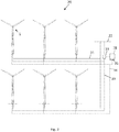
- Figure 2 illustrates a collection of wind turbines 1 belonging to a wind power plant 20, also referred to as a wind farm or wind park, that serves as a power generating plant connected by transmission lines 21 with a power grid 22.
- the power grid generally consists of a network of power stations, transmission circuits, and substations coupled by a network of transmission lines that transmits the power to loads in the form of end users and other customers of electrical utilities.
- the figure illustrates six wind turbines, a wind power plant may comprise less or more wind turbines.
- Figure 3 illustrates a schematic representation of a power management system according to embodiments of the present invention.
- Figure 3 illustrates a power supply with a limited capacity 7 and a number of power consuming units (PCU) 30A-30D.
- PCU power consuming units
- Examples of power consuming units include, but are not limited to, yaw motors for yawing the turbine, pumps and power supplies for operating the hydraulic system, power supplies for operating the cooling system, power supplies for operating the heating system, power supplies to operate to turn the rotor to adjust the azimuthal position of the blades, pumps for lubricating moving parts that are in need of lubrication, and other elements used in a wind turbine which require and consume power in order to operate.
- the various power supplies may be in the form of voltage transformers.
- the power management system comprises a dispatcher 31 connected via a communication line 34 to the power supply 7 in order to access the available capacity of the power supply.
- the dispatcher may also be referred to as a power manager.
- the power management system further comprises a requester 32 connected to the power consuming units 30A to 30D.
- the requester is arranged to control the power consumption of the power consuming units. This may be done in any appropriate way, e.g. by providing an input to the power consuming unit which enables or disables the unit.
- the power management system When a need for power arises, e.g. in connection with a grid loss situation or other decoupling of the turbines from the grid, it is the role of the power management system to make sure that important or certain power consuming units is supplied with a sufficient amount of power. In an embodiment, this is done by arranging the requester to forward a request to the dispatcher for an amount of power. Based on the available capacity of the power supply, the dispatcher either allows the power consuming unit to consume the amount of power or denies the power consuming unit to consume the amount of power. If a power consuming unit is allowed to consume power it draws power from the power supply 7 via an electrical connection 33 between the power consuming units and the power supply.
- the requester 32 is illustrated as a separate unit connected to the power consuming units 30A-30D, however other embodiments are also possible.
- each power consuming unit may be provided with a dedicated requester.
- groups of power consuming units such as units directed to rotor control or units directed to yaw control, may be connected to a group requester.
- the requester may in embodiments comprise instructions as to which power consuming units that are in need of power in a grid loss situation. However, the requester may also be connected to, or implemented by, a control system which is ensured power at all time. While the requester may be implemented in hardware, it is typically a computing unit which is instructed by computer instructions to perform its tasks. The requester may also be implemented as a software component, or electronic component, which is electrically connected to the power consuming units.
- the dispatcher may in embodiments also comprise instructions as to which power consuming units that are in need of power in a grid loss situation, as well as the role of the various power consuming units in a grid loss situation.
- the dispatcher may also be connected to, or implemented by, a control system which is ensured power at all time. While the dispatcher may be implemented in hardware, it is typically a computing unit which is instructed by computer instructions to perform its tasks.
- the dispatcher may also be implemented as a software component, or electronic component, which is electrically coupled to the power consuming units.
- the requester and/or the dispatcher may also be implemented as part of the wind turbine control system, such as a in a safety-certified control system, or connected to the wind turbine control system.
- the dispatcher does not actively monitor the available capacity of the power supply, instead it may access the available capacity of the power supply, e.g. upon a grid loss or from a registry, to determine the start capacity, and then based on the requests that are allowed determine the available capacity during the power loss. In another embodiment, the dispatcher actively monitors the actual power capacity of the power supply so that the allowed requests are based on measured values of the available capacity.
- a switch element may connect the internal power supply grid 33 to the power supply with the limited capacity 7, 7A, 7B, and thereby provide access to power for the power consuming units.
- the requesters of the various power consuming units upon a need of power forwards a request to the dispatcher for an amount of power.
- the role of the dispatcher is to either allow the power consuming units to consume the amount of power or deny the power consuming unit to consume the amount of power, in accordance with the available capacity of the power supply.
- Figure 1 further illustrates an embodiment of the power supply with the limited capacity 7A connected to the wind turbine via communication line 33 and power line 34.
- the power supply is a single turbine emergency power supply dedicated to support a single turbine during grid loss. That is the dispatcher and the requester are local to the specific turbine.
- Figure 2 further illustrates an embodiment of the power supply with the limited capacity 7B connected to the wind turbines via communication line 33 and power line 34.
- the dispatcher 31 is illustrated together with the power supply 7B.
- the power supply is a wind power plant emergency power supply dedicated to support all, or at least some of the wind turbines in the wind power plant.
- the dispatcher and the requester may both be local to the power supply.
- the requester may be local to the turbines, whereas the dispatcher is local to the power supply.
- one of, or both the requester and the dispatcher may be implemented together with, or part of, a power plant controller.
- the power supply 7, 7A, 7B may in embodiments be a diesel generator and/or a battery supply.
- the battery supply may be based on rechargeable batteries.
- the rechargeable batteries may be charged during grid connection and used for power supply during grid loss.
- the capacity of the power supply is scaled according to the number of turbines it needs to support, as well as to the number and nature of power consuming units it needs to support.
- the power supply may be used for any purpose, but in a typical situation it is an emergency power supply arranged for supplying power in the event of the one or more turbines are disconnected from the grid.
- the dispatcher may send information to a requester about a base load, so that a unit is allowed to consume an amount of power up to the base load without forwarding a request for an amount of power. This may be used in a situation where the power supply is scaled to supply the idle consumption of any units, e.g. voltage transformers, that are operating during grid loss. Should the power consuming unit need further power than what is covered by the base load, it sends a request for more power to the dispatcher.
- the power management system may be disabled by setting the base load to infinity.
- a request may as a minimum comprise an element, i.e. a data element, containing the power demand.
- a priority may be included. The priority may be scaled in a manner so that the highest priority are given to power consuming units which risk to damage the turbine or parts of the turbine if not granted.
- the dispatcher grants requests with highest priority, whereas a lower priority request is granted according to a set of dispatch rules. However, all priorities may be handled in accordance with dispatch rules.
- the request may also comprise a time period to indicate the duration of the power consumption.
- the dispatcher may reply with a response.
- the response may in an embodiment comprise a permission to consume a specified amount of power.
- the permission may be conditioned upon a number of limitations. Such limitations may be an upper limit of the power consumption and a time period during which it needs to draw the power. By imposing an upper limit, the turbine may still be able to perform the desired action, but possibly slower.
- the duration may e.g. be imposed to ensure that the power drawn from the various units are spread in time, to reduce the peak consumption.
- the system trusts that the power consuming units only draw power when allowed so, and does not draw power when not allowed to.
- This may be improved by implementing the requester in a manner so that the requester is arranged to connect the power consuming unit to the power supply and draw the allow amount of power from the power supply when allowed by the dispatcher, and arranged to disconnect the power consuming unit from the power supply when denied by the dispatcher to consume power.
- a switch may be used which opens or closes, and thereby provide electrical connection only in periods when allowed.
- the dispatcher allows the power consuming unit to consume the amount of power or denies the power consuming unit to consume the amount of power based on at least one further input directed to an operational state or physical state of one or more of the wind turbines or a power consuming unit.
- the input directed to the operational state or the physical state may be provided as part of the request or it may be provided as a separate input to the dispatcher, e.g. provided from the turbine controller and/or sensors in the turbine.
- an operational state may be whether or not a power consuming unit is in a standby state or shutdown state.
- the power needed to start the power consuming unit from shutdown may be impermissible, whereas the power need to wake the unit from standby may be permissible.
- a pump may use 5 kW in standby, which may have been allowed by an earlier request and 50 kW during normal operation at no additional cost, however, to start-up the pump from shutdown may require 150 kW. In such situations, use of the pump may be allowed if it is in standby, but may not be allowed if start up from shutdown is needed.
- Another operational state may e.g. be the temperature of a given component. This may e.g. be used to decide whether or not a cooling system can be operated, so that cooling is only activated for critical temperatures, whereas components with non-critical temperatures are not cooled, even though they would have been cooled if the power capacity had been unlimited.
- a physical state may e.g. be the position of the yaw. It may be critical that certain turbines are allowed to yaw, whereas others are not, e.g. dependent on the wind direction. Edgewise vibrations may risk building up and damage the blades if the turbine is not allowed to yaw upwind. The risk may be higher for certain yaw positions than for other.
- the physical state may also be directed to a blade vibration sensor, so that a turbine is only allowed to yaw (i.e. consume power), if the blade vibration is above a given threshold.
- Another example of the physical state is the azimuthal position of the rotor, so that rotors where a blade is in risk of hitting the tower are allowed to be turned, whereas rotors which are stopped in a position where tower strike is not a risk are not allowed to turn.
- FIG. 4 illustrates an embodiment of a power management system and a method of operating the system.
- the dispatcher 31 is implemented into the power plant controller PPC 40, which can access the available capacity of the limited power supply, LPS.
- the requester 32 is implemented into the winds turbine controller WTC, 41. Also the control of a number of power consuming units PCUs connected to the requester is illustrated.
- the wind turbine needs to operate one of the power consuming units by power delivered from the power supply with limited capacity.
- An instruction to operate the power consuming unit is generated, for example by the control system of the power consuming unit itself or by the wind turbine controller WTC, this instruction 42 is received by the requester.
- a request 43 for an amount of power for operating the power consuming unit is forwarded from the requester to the dispatcher.
- the dispatcher 31 access 44 an available capacity of the power supply, and determine whether the amount of power can be used based on the available capacity of the power supply, and generate a request result response 45, e.g. in the form of a permission, which either allow the power consuming unit to consume the amount of power or deny the power consuming unit to consume the amount of power in accordance with the request result. Based on the result, the power consuming unit will either be operated or not.
Landscapes
- Engineering & Computer Science (AREA)
- Life Sciences & Earth Sciences (AREA)
- Sustainable Development (AREA)
- Sustainable Energy (AREA)
- Chemical & Material Sciences (AREA)
- Combustion & Propulsion (AREA)
- Mechanical Engineering (AREA)
- General Engineering & Computer Science (AREA)
- Supply And Distribution Of Alternating Current (AREA)
- Wind Motors (AREA)
- Remote Monitoring And Control Of Power-Distribution Networks (AREA)
Claims (14)
- Leistungssteuersystem für eine oder mehrere Windturbinen (1), wobei die eine oder die mehreren Windturbinen an eine Stromversorgung (7) mit einer beschränkten Kapazität angeschlossen sind, und die eine oder die mehreren Windturbinen jeweils eine Anzahl von Stromaufnahmeeinheiten (PCU) umfassen; wobei das Leistungssteuersystem Folgendes umfasst:einen Umrichter (31), der an der Stromversorgung angeschlossen ist, um auf eine verfügbare Kapazität der Stromversorgung zuzugreifen;einen Anforderer (32), der an mindestens einer Stromaufnahmeeinheit angeschlossen ist, wobei der Anforderer angeordnet ist, um den Leistungsverbrauch der Stromaufnahmeeinheit zu steuern;wobei der Anforderer nach einem Bedarf einer Stromaufnahmeeinheit zum Verbrauchen von Leistung eine Anforderung nach einer Menge von Leistung an den Umrichter weiterleitet, und wobei der Umrichter basierend auf der verfügbaren Kapazität der Stromversorgung der Stromaufnahmeeinheit entweder zulässt, die Menge an Leistung zu verbrauchen, oder es der Stromaufnahmeeinheit verwehrt, die Menge an Leistung zu verbrauchen;dadurch gekennzeichnet, dass der Umrichter Informationen über eine Basislast an den Anforderer sendet, und wobei es einer Einheit zugelassen wird, eine Menge von Leistung bis zu der Basislast zu verbrauchen, ohne eine Anforderung für eine Menge an Leistung weiterzuleiten.
- System nach einem der vorstehenden Ansprüche, wobei die Anforderung mindestens eine Leistungsanforderung und eine Priorität umfasst.
- System nach einem der vorstehenden Ansprüche, wobei die Anforderung einen Zeitraum umfasst.
- System nach einem der vorstehenden Ansprüche, wobei der Umrichter nach Erhalt einer Anforderung Informationen an den Anforderer sendet, einschließlich einer Zulassung, eine festgelegte Menge an Leistung zu verbrauchen.
- System nach einem der vorstehenden Ansprüche, wobei der Umrichter es der Stromaufnahmeeinheit zulässt, die Menge an Leistung zu verbrauchen, oder es der Stromaufnahmeeinheit verwehrt, die Menge an Leistung zu verbrauchen, basierend auf mindestens einer weiteren Eingabe, die sich an einen Betriebsstatus oder einen physikalischen Status einer oder mehrerer Windturbinen oder einer Stromaufnahmeeinheit richtet.
- System nach einem der vorstehenden Ansprüche, wobei die Stromversorgung eine Notstromversorgung ist, die zur Stromversorgung angeordnet ist, im Falle, dass eine oder mehrere Turbinen von dem Netz getrennt wird/werden.
- System nach einem der vorstehenden Ansprüche, wobei der Anforderer angeordnet ist, um die Stromaufnahmeeinheit an die Stromversorgung anzuschließen und die zulässige Menge an Leistung von der Stromversorgung zu beziehen, wenn von dem Umrichter zugelassen, und angeordnet ist, um die Stromaufnahmeeinheit von der Stromversorgung zu trennen, wenn der Leistungsverbrauch von dem Umrichter verwehrt ist.
- System nach einem der vorstehenden Ansprüche, wobei es sich bei der einen oder den mehreren Turbinen um eine Turbine handelt, und wobei die Stromversorgung eine Notstromversorgung einer einzelnen Turbine ist.
- System nach einem der Ansprüche 1-7, wobei die eine oder die mehreren Turbinen zwei oder mehr Turbinen sind, die als eine Windkraftanlage angeordnet sind, und wobei die Stromversorgung eine Windkraftanlagen-Notstromversorgung ist.
- System nach einem der vorstehenden Ansprüche, wobei die Stromversorgung ein Dieselgenerator ist.
- System nach einem der vorstehenden Ansprüche, wobei die Stromversorgung eine Batterieversorgung ist.
- System nach Anspruch 10, wobei die Batterieversorgung auf wiederaufladbaren Batterien basiert.
- Windturbinensystem, umfassend eine oder mehrere Windturbinen und ein Leistungssteuersystem nach einem der Ansprüche 1-13.
- Verfahren der Leistungssteuerung einer oder mehrerer Windturbinen (1), wobei die eine oder die mehreren Windturbinen an einer Stromversorgung (7) mit beschränkter Kapazität angeschlossen ist, und die eine oder die mehreren Windturbinen jeweils eine Anzahl von Stromaufnahmeeinheiten (PCU) umfassen; wobei das Verfahren Folgendes umfasst:Empfangen einer Anweisung, eine Stromaufnahmeeinheit zu betreiben;Feststellen einer Menge an Leistung zum Betrieben der Stromaufnahmeeinheit;dadurch gekennzeichnet, dass das Verfahren weiter das Feststellen einer Basislast umfasst, bis zu welcher es der Einheit zulässig ist, Leistung zu verbrauchen;falls die Menge an Leistung geringer ist als die Basislast, das Zulassen der Stromaufnahmeeinheit, die Menge an Leistung zu verbrauchen; undfalls die Menge an Leistung höher ist als die Basislast:Anforderung einer Menge an Leistung für das Betrieben der Stromaufnahmeeinheit;Zugang einer verfügbaren Kapazität der Stromversorgung;Feststellen, ob die Menge an Leistung basierend auf der verfügbaren Kapazität der Stromversorgung verwendet werden kann, und Generieren eines Anforderungsergebnisses; undgemäß dem Anforderungsergebnis, entweder das Zulassen der Stromaufnahmeeinheit, die Menge an Leistung zu verbrauchen, oder das Verwehren der Stromaufnahmeeinheit, die Menge an Leistung verbrauchen.
Applications Claiming Priority (2)
| Application Number | Priority Date | Filing Date | Title |
|---|---|---|---|
| DKPA201570018 | 2015-01-15 | ||
| PCT/DK2016/050008 WO2016112918A1 (en) | 2015-01-15 | 2016-01-12 | Power management system for wind turbine(s) being connected to a power supply with a limited capacity |
Publications (2)
| Publication Number | Publication Date |
|---|---|
| EP3245400A1 EP3245400A1 (de) | 2017-11-22 |
| EP3245400B1 true EP3245400B1 (de) | 2019-01-09 |
Family
ID=55168081
Family Applications (1)
| Application Number | Title | Priority Date | Filing Date |
|---|---|---|---|
| EP16700683.2A Active EP3245400B1 (de) | 2015-01-15 | 2016-01-12 | Leistungsverwaltungssystem für windturbinen, die an eine stromversorgung mit begrenzter kapazität angeschlossen sind |
Country Status (5)
| Country | Link |
|---|---|
| US (1) | US11448186B2 (de) |
| EP (1) | EP3245400B1 (de) |
| CN (1) | CN107223183B (de) |
| ES (1) | ES2710428T3 (de) |
| WO (1) | WO2016112918A1 (de) |
Cited By (1)
| Publication number | Priority date | Publication date | Assignee | Title |
|---|---|---|---|---|
| US11635059B2 (en) | 2021-08-16 | 2023-04-25 | Vestas Wind Systems A/S | Wind turbine power plant with power saving control method |
Families Citing this family (10)
| Publication number | Priority date | Publication date | Assignee | Title |
|---|---|---|---|---|
| DE102018112825A1 (de) * | 2018-05-29 | 2019-12-05 | fos4X GmbH | Sensoranordnung für eine Windkraftanlage |
| US11509141B2 (en) | 2018-07-10 | 2022-11-22 | Vestas Wind Sysiems A/S | Wind turbine power consumption control |
| TW202026524A (zh) | 2018-11-07 | 2020-07-16 | 丹麥商菱重維斯塔斯海上風力有限公司 | 待機模式中的風力渦輪葉片的俯仰控制技術 |
| EP3663573B1 (de) | 2018-12-04 | 2022-08-24 | General Electric Renovables España S.L. | Verfahren zur verringerung der schwingungen von rotorblättern einer windturbine |
| EP3859144A1 (de) * | 2020-01-29 | 2021-08-04 | Siemens Gamesa Renewable Energy A/S | Verminderung der stillstandsschwingungen einer windturbine |
| CN113250903A (zh) * | 2021-06-07 | 2021-08-13 | 天津瑞能电气有限公司 | 风力发电机组应急偏航控制装置和控制方法 |
| ES3064840T3 (en) * | 2021-10-01 | 2026-04-29 | Vestas Wind Systems As | Wind turbine power plant with peak power consumption control |
| EP4239191A1 (de) * | 2022-03-03 | 2023-09-06 | Siemens Gamesa Renewable Energy A/S | Lastplanung von windturbinenhilfsvorrichtungen |
| CN115434853B (zh) * | 2022-09-20 | 2025-09-12 | 三一重能股份有限公司 | 一种风电机组偏航控制方法、装置及系统 |
| CN117514651B (zh) * | 2023-12-13 | 2025-02-14 | 远景能源有限公司 | 一种后备电源控制装置、系统、风力发电机组及方法 |
Family Cites Families (9)
| Publication number | Priority date | Publication date | Assignee | Title |
|---|---|---|---|---|
| ES2265771B1 (es) | 2005-07-22 | 2008-01-16 | GAMESA INNOVATION & TECHNOLOGY, S.L. | Metodo para mantener operativos los componentes de una turbina eolica y una turbina eolica con componentes que permitan el mantenimiento operativo. |
| CN201022153Y (zh) | 2007-02-27 | 2008-02-13 | 叶明祥 | 不断电电力储存装置 |
| EP1993184B2 (de) * | 2007-05-14 | 2024-04-24 | Siemens Gamesa Renewable Energy A/S | Verfahren zum Starten mindestens eines Teils einer Windkraftanlage, Windkraftanlage und Verwendung der Windkraftanlage |
| EP2166225B1 (de) | 2008-09-19 | 2016-08-10 | Vestas Wind Systems A/S | Windpark mit einem Hilfsstromkreis |
| DE102010056458A1 (de) * | 2010-12-29 | 2012-07-05 | Repower Systems Ag | Windpark und Verfahren zum Betreiben eines Windparks |
| KR101225859B1 (ko) | 2011-05-31 | 2013-01-24 | 엘에스산전 주식회사 | 에너지 관리장치 및 에너지 관리방법과, 에너지 관리장치를 구비하는 에너지 관리시스템 |
| EP2565443A1 (de) * | 2011-09-05 | 2013-03-06 | XEMC Darwind B.V. | Erzeugung von Hilfsstrom für eine Windturbine |
| CN202914251U (zh) | 2012-11-12 | 2013-05-01 | 国电联合动力技术有限公司 | 一种大型风电机组的辅助发电装置 |
| US9677540B2 (en) | 2012-11-29 | 2017-06-13 | General Electric Company | System and method for providing yaw backup to a wind farm |
-
2016
- 2016-01-12 EP EP16700683.2A patent/EP3245400B1/de active Active
- 2016-01-12 ES ES16700683T patent/ES2710428T3/es active Active
- 2016-01-12 US US15/543,859 patent/US11448186B2/en active Active
- 2016-01-12 WO PCT/DK2016/050008 patent/WO2016112918A1/en not_active Ceased
- 2016-01-12 CN CN201680010375.3A patent/CN107223183B/zh active Active
Non-Patent Citations (1)
| Title |
|---|
| None * |
Cited By (1)
| Publication number | Priority date | Publication date | Assignee | Title |
|---|---|---|---|---|
| US11635059B2 (en) | 2021-08-16 | 2023-04-25 | Vestas Wind Systems A/S | Wind turbine power plant with power saving control method |
Also Published As
| Publication number | Publication date |
|---|---|
| US20180266391A1 (en) | 2018-09-20 |
| CN107223183A (zh) | 2017-09-29 |
| CN107223183B (zh) | 2020-06-16 |
| WO2016112918A1 (en) | 2016-07-21 |
| EP3245400A1 (de) | 2017-11-22 |
| US11448186B2 (en) | 2022-09-20 |
| ES2710428T3 (es) | 2019-04-25 |
Similar Documents
| Publication | Publication Date | Title |
|---|---|---|
| EP3245400B1 (de) | Leistungsverwaltungssystem für windturbinen, die an eine stromversorgung mit begrenzter kapazität angeschlossen sind | |
| EP2166225B1 (de) | Windpark mit einem Hilfsstromkreis | |
| EP3149325B1 (de) | Windkraftanlage mit verringerten verlusten | |
| US8975784B2 (en) | Method for managing an electrical network | |
| CN103140670B (zh) | 风电场和用于运行风电场的方法 | |
| EP3051124B1 (de) | Verfahren zum Betreiben einer Windturbine ohne Netzanbindung und Windturbine | |
| JP5963424B2 (ja) | 風力タービンの電気装置を制御する方法およびシステム | |
| US10153641B2 (en) | Extending black-start availability using energy storage systems | |
| EP2315939B1 (de) | Windturbine und energieversorgungssystem | |
| US12348041B2 (en) | Wind turbine and method | |
| US20240392746A1 (en) | Operation of a disconnected wind turbine | |
| CN107800190B (zh) | 风力发电机组备电系统及其控制方法 | |
| CN205335860U (zh) | 风力发电机组及其微网供电装置 | |
| EP4409133B1 (de) | Windturbinenkraftwerk mit spitzenleistungsverbrauchssteuerung | |
| EP4239191A1 (de) | Lastplanung von windturbinenhilfsvorrichtungen | |
| CN117895563A (zh) | 大兆瓦风力发电机组主控变流器控制方法及装置 | |
| CN120978967A (zh) | 风电机组的失电保护系统及其供电方法 | |
| KR20150107297A (ko) | 풍력 발전 시스템의 비상 전원 공급 장치 및 방법 |
Legal Events
| Date | Code | Title | Description |
|---|---|---|---|
| STAA | Information on the status of an ep patent application or granted ep patent |
Free format text: STATUS: THE INTERNATIONAL PUBLICATION HAS BEEN MADE |
|
| PUAI | Public reference made under article 153(3) epc to a published international application that has entered the european phase |
Free format text: ORIGINAL CODE: 0009012 |
|
| STAA | Information on the status of an ep patent application or granted ep patent |
Free format text: STATUS: REQUEST FOR EXAMINATION WAS MADE |
|
| 17P | Request for examination filed |
Effective date: 20170710 |
|
| AK | Designated contracting states |
Kind code of ref document: A1 Designated state(s): AL AT BE BG CH CY CZ DE DK EE ES FI FR GB GR HR HU IE IS IT LI LT LU LV MC MK MT NL NO PL PT RO RS SE SI SK SM TR |
|
| AX | Request for extension of the european patent |
Extension state: BA ME |
|
| DAV | Request for validation of the european patent (deleted) | ||
| DAX | Request for extension of the european patent (deleted) | ||
| GRAP | Despatch of communication of intention to grant a patent |
Free format text: ORIGINAL CODE: EPIDOSNIGR1 |
|
| STAA | Information on the status of an ep patent application or granted ep patent |
Free format text: STATUS: GRANT OF PATENT IS INTENDED |
|
| INTG | Intention to grant announced |
Effective date: 20180918 |
|
| GRAS | Grant fee paid |
Free format text: ORIGINAL CODE: EPIDOSNIGR3 |
|
| GRAA | (expected) grant |
Free format text: ORIGINAL CODE: 0009210 |
|
| STAA | Information on the status of an ep patent application or granted ep patent |
Free format text: STATUS: THE PATENT HAS BEEN GRANTED |
|
| AK | Designated contracting states |
Kind code of ref document: B1 Designated state(s): AL AT BE BG CH CY CZ DE DK EE ES FI FR GB GR HR HU IE IS IT LI LT LU LV MC MK MT NL NO PL PT RO RS SE SI SK SM TR |
|
| REG | Reference to a national code |
Ref country code: GB Ref legal event code: FG4D |
|
| REG | Reference to a national code |
Ref country code: CH Ref legal event code: EP Ref country code: AT Ref legal event code: REF Ref document number: 1087629 Country of ref document: AT Kind code of ref document: T Effective date: 20190115 |
|
| REG | Reference to a national code |
Ref country code: IE Ref legal event code: FG4D |
|
| REG | Reference to a national code |
Ref country code: DE Ref legal event code: R096 Ref document number: 602016009218 Country of ref document: DE |
|
| REG | Reference to a national code |
Ref country code: ES Ref legal event code: FG2A Ref document number: 2710428 Country of ref document: ES Kind code of ref document: T3 Effective date: 20190425 |
|
| REG | Reference to a national code |
Ref country code: NL Ref legal event code: MP Effective date: 20190109 |
|
| REG | Reference to a national code |
Ref country code: LT Ref legal event code: MG4D |
|
| PG25 | Lapsed in a contracting state [announced via postgrant information from national office to epo] |
Ref country code: NL Free format text: LAPSE BECAUSE OF FAILURE TO SUBMIT A TRANSLATION OF THE DESCRIPTION OR TO PAY THE FEE WITHIN THE PRESCRIBED TIME-LIMIT Effective date: 20190109 |
|
| REG | Reference to a national code |
Ref country code: AT Ref legal event code: MK05 Ref document number: 1087629 Country of ref document: AT Kind code of ref document: T Effective date: 20190109 |
|
| PG25 | Lapsed in a contracting state [announced via postgrant information from national office to epo] |
Ref country code: LT Free format text: LAPSE BECAUSE OF FAILURE TO SUBMIT A TRANSLATION OF THE DESCRIPTION OR TO PAY THE FEE WITHIN THE PRESCRIBED TIME-LIMIT Effective date: 20190109 Ref country code: FI Free format text: LAPSE BECAUSE OF FAILURE TO SUBMIT A TRANSLATION OF THE DESCRIPTION OR TO PAY THE FEE WITHIN THE PRESCRIBED TIME-LIMIT Effective date: 20190109 Ref country code: NO Free format text: LAPSE BECAUSE OF FAILURE TO SUBMIT A TRANSLATION OF THE DESCRIPTION OR TO PAY THE FEE WITHIN THE PRESCRIBED TIME-LIMIT Effective date: 20190409 Ref country code: PT Free format text: LAPSE BECAUSE OF FAILURE TO SUBMIT A TRANSLATION OF THE DESCRIPTION OR TO PAY THE FEE WITHIN THE PRESCRIBED TIME-LIMIT Effective date: 20190509 Ref country code: SE Free format text: LAPSE BECAUSE OF FAILURE TO SUBMIT A TRANSLATION OF THE DESCRIPTION OR TO PAY THE FEE WITHIN THE PRESCRIBED TIME-LIMIT Effective date: 20190109 Ref country code: PL Free format text: LAPSE BECAUSE OF FAILURE TO SUBMIT A TRANSLATION OF THE DESCRIPTION OR TO PAY THE FEE WITHIN THE PRESCRIBED TIME-LIMIT Effective date: 20190109 |
|
| PG25 | Lapsed in a contracting state [announced via postgrant information from national office to epo] |
Ref country code: IS Free format text: LAPSE BECAUSE OF FAILURE TO SUBMIT A TRANSLATION OF THE DESCRIPTION OR TO PAY THE FEE WITHIN THE PRESCRIBED TIME-LIMIT Effective date: 20190509 Ref country code: LV Free format text: LAPSE BECAUSE OF FAILURE TO SUBMIT A TRANSLATION OF THE DESCRIPTION OR TO PAY THE FEE WITHIN THE PRESCRIBED TIME-LIMIT Effective date: 20190109 Ref country code: HR Free format text: LAPSE BECAUSE OF FAILURE TO SUBMIT A TRANSLATION OF THE DESCRIPTION OR TO PAY THE FEE WITHIN THE PRESCRIBED TIME-LIMIT Effective date: 20190109 Ref country code: BG Free format text: LAPSE BECAUSE OF FAILURE TO SUBMIT A TRANSLATION OF THE DESCRIPTION OR TO PAY THE FEE WITHIN THE PRESCRIBED TIME-LIMIT Effective date: 20190409 Ref country code: RS Free format text: LAPSE BECAUSE OF FAILURE TO SUBMIT A TRANSLATION OF THE DESCRIPTION OR TO PAY THE FEE WITHIN THE PRESCRIBED TIME-LIMIT Effective date: 20190109 Ref country code: GR Free format text: LAPSE BECAUSE OF FAILURE TO SUBMIT A TRANSLATION OF THE DESCRIPTION OR TO PAY THE FEE WITHIN THE PRESCRIBED TIME-LIMIT Effective date: 20190410 |
|
| REG | Reference to a national code |
Ref country code: CH Ref legal event code: PL |
|
| PG25 | Lapsed in a contracting state [announced via postgrant information from national office to epo] |
Ref country code: LU Free format text: LAPSE BECAUSE OF NON-PAYMENT OF DUE FEES Effective date: 20190112 |
|
| REG | Reference to a national code |
Ref country code: DE Ref legal event code: R097 Ref document number: 602016009218 Country of ref document: DE |
|
| REG | Reference to a national code |
Ref country code: BE Ref legal event code: MM Effective date: 20190131 |
|
| REG | Reference to a national code |
Ref country code: IE Ref legal event code: MM4A |
|
| PG25 | Lapsed in a contracting state [announced via postgrant information from national office to epo] |
Ref country code: MC Free format text: LAPSE BECAUSE OF FAILURE TO SUBMIT A TRANSLATION OF THE DESCRIPTION OR TO PAY THE FEE WITHIN THE PRESCRIBED TIME-LIMIT Effective date: 20190109 Ref country code: AT Free format text: LAPSE BECAUSE OF FAILURE TO SUBMIT A TRANSLATION OF THE DESCRIPTION OR TO PAY THE FEE WITHIN THE PRESCRIBED TIME-LIMIT Effective date: 20190109 Ref country code: DK Free format text: LAPSE BECAUSE OF FAILURE TO SUBMIT A TRANSLATION OF THE DESCRIPTION OR TO PAY THE FEE WITHIN THE PRESCRIBED TIME-LIMIT Effective date: 20190109 Ref country code: EE Free format text: LAPSE BECAUSE OF FAILURE TO SUBMIT A TRANSLATION OF THE DESCRIPTION OR TO PAY THE FEE WITHIN THE PRESCRIBED TIME-LIMIT Effective date: 20190109 Ref country code: RO Free format text: LAPSE BECAUSE OF FAILURE TO SUBMIT A TRANSLATION OF THE DESCRIPTION OR TO PAY THE FEE WITHIN THE PRESCRIBED TIME-LIMIT Effective date: 20190109 Ref country code: CZ Free format text: LAPSE BECAUSE OF FAILURE TO SUBMIT A TRANSLATION OF THE DESCRIPTION OR TO PAY THE FEE WITHIN THE PRESCRIBED TIME-LIMIT Effective date: 20190109 Ref country code: SK Free format text: LAPSE BECAUSE OF FAILURE TO SUBMIT A TRANSLATION OF THE DESCRIPTION OR TO PAY THE FEE WITHIN THE PRESCRIBED TIME-LIMIT Effective date: 20190109 Ref country code: IT Free format text: LAPSE BECAUSE OF FAILURE TO SUBMIT A TRANSLATION OF THE DESCRIPTION OR TO PAY THE FEE WITHIN THE PRESCRIBED TIME-LIMIT Effective date: 20190109 Ref country code: AL Free format text: LAPSE BECAUSE OF FAILURE TO SUBMIT A TRANSLATION OF THE DESCRIPTION OR TO PAY THE FEE WITHIN THE PRESCRIBED TIME-LIMIT Effective date: 20190109 |
|
| PLBE | No opposition filed within time limit |
Free format text: ORIGINAL CODE: 0009261 |
|
| STAA | Information on the status of an ep patent application or granted ep patent |
Free format text: STATUS: NO OPPOSITION FILED WITHIN TIME LIMIT |
|
| PG25 | Lapsed in a contracting state [announced via postgrant information from national office to epo] |
Ref country code: BE Free format text: LAPSE BECAUSE OF NON-PAYMENT OF DUE FEES Effective date: 20190131 |
|
| 26N | No opposition filed |
Effective date: 20191010 |
|
| PG25 | Lapsed in a contracting state [announced via postgrant information from national office to epo] |
Ref country code: CH Free format text: LAPSE BECAUSE OF NON-PAYMENT OF DUE FEES Effective date: 20190131 Ref country code: LI Free format text: LAPSE BECAUSE OF NON-PAYMENT OF DUE FEES Effective date: 20190131 |
|
| PG25 | Lapsed in a contracting state [announced via postgrant information from national office to epo] |
Ref country code: IE Free format text: LAPSE BECAUSE OF NON-PAYMENT OF DUE FEES Effective date: 20190112 |
|
| PG25 | Lapsed in a contracting state [announced via postgrant information from national office to epo] |
Ref country code: SI Free format text: LAPSE BECAUSE OF FAILURE TO SUBMIT A TRANSLATION OF THE DESCRIPTION OR TO PAY THE FEE WITHIN THE PRESCRIBED TIME-LIMIT Effective date: 20190109 |
|
| PG25 | Lapsed in a contracting state [announced via postgrant information from national office to epo] |
Ref country code: TR Free format text: LAPSE BECAUSE OF FAILURE TO SUBMIT A TRANSLATION OF THE DESCRIPTION OR TO PAY THE FEE WITHIN THE PRESCRIBED TIME-LIMIT Effective date: 20190109 |
|
| PG25 | Lapsed in a contracting state [announced via postgrant information from national office to epo] |
Ref country code: MT Free format text: LAPSE BECAUSE OF NON-PAYMENT OF DUE FEES Effective date: 20190112 |
|
| PG25 | Lapsed in a contracting state [announced via postgrant information from national office to epo] |
Ref country code: CY Free format text: LAPSE BECAUSE OF FAILURE TO SUBMIT A TRANSLATION OF THE DESCRIPTION OR TO PAY THE FEE WITHIN THE PRESCRIBED TIME-LIMIT Effective date: 20190109 |
|
| PG25 | Lapsed in a contracting state [announced via postgrant information from national office to epo] |
Ref country code: SM Free format text: LAPSE BECAUSE OF FAILURE TO SUBMIT A TRANSLATION OF THE DESCRIPTION OR TO PAY THE FEE WITHIN THE PRESCRIBED TIME-LIMIT Effective date: 20190109 |
|
| PG25 | Lapsed in a contracting state [announced via postgrant information from national office to epo] |
Ref country code: HU Free format text: LAPSE BECAUSE OF FAILURE TO SUBMIT A TRANSLATION OF THE DESCRIPTION OR TO PAY THE FEE WITHIN THE PRESCRIBED TIME-LIMIT; INVALID AB INITIO Effective date: 20160112 |
|
| PG25 | Lapsed in a contracting state [announced via postgrant information from national office to epo] |
Ref country code: MK Free format text: LAPSE BECAUSE OF FAILURE TO SUBMIT A TRANSLATION OF THE DESCRIPTION OR TO PAY THE FEE WITHIN THE PRESCRIBED TIME-LIMIT Effective date: 20190109 |
|
| P01 | Opt-out of the competence of the unified patent court (upc) registered |
Effective date: 20230521 |
|
| PGFP | Annual fee paid to national office [announced via postgrant information from national office to epo] |
Ref country code: GB Payment date: 20260126 Year of fee payment: 11 |
|
| PGFP | Annual fee paid to national office [announced via postgrant information from national office to epo] |
Ref country code: ES Payment date: 20260210 Year of fee payment: 11 |
|
| PGFP | Annual fee paid to national office [announced via postgrant information from national office to epo] |
Ref country code: DE Payment date: 20260127 Year of fee payment: 11 |
|
| PGFP | Annual fee paid to national office [announced via postgrant information from national office to epo] |
Ref country code: FR Payment date: 20260126 Year of fee payment: 11 |