EP3245426B1 - Ölpumpenanordnung für ein kraftfahrzeug - Google Patents
Ölpumpenanordnung für ein kraftfahrzeug Download PDFInfo
- Publication number
- EP3245426B1 EP3245426B1 EP16721628.2A EP16721628A EP3245426B1 EP 3245426 B1 EP3245426 B1 EP 3245426B1 EP 16721628 A EP16721628 A EP 16721628A EP 3245426 B1 EP3245426 B1 EP 3245426B1
- Authority
- EP
- European Patent Office
- Prior art keywords
- pump
- oil
- housing
- oil pump
- motor
- Prior art date
- Legal status (The legal status is an assumption and is not a legal conclusion. Google has not performed a legal analysis and makes no representation as to the accuracy of the status listed.)
- Active
Links
Images


Classifications
-
- F—MECHANICAL ENGINEERING; LIGHTING; HEATING; WEAPONS; BLASTING
- F16—ENGINEERING ELEMENTS AND UNITS; GENERAL MEASURES FOR PRODUCING AND MAINTAINING EFFECTIVE FUNCTIONING OF MACHINES OR INSTALLATIONS; THERMAL INSULATION IN GENERAL
- F16H—GEARING
- F16H57/00—General details of gearing
- F16H57/04—Features relating to lubrication or cooling or heating
- F16H57/0434—Features relating to lubrication or cooling or heating relating to lubrication supply, e.g. pumps; Pressure control
- F16H57/0441—Arrangements of pumps
-
- F—MECHANICAL ENGINEERING; LIGHTING; HEATING; WEAPONS; BLASTING
- F16—ENGINEERING ELEMENTS AND UNITS; GENERAL MEASURES FOR PRODUCING AND MAINTAINING EFFECTIVE FUNCTIONING OF MACHINES OR INSTALLATIONS; THERMAL INSULATION IN GENERAL
- F16H—GEARING
- F16H57/00—General details of gearing
- F16H57/02—Gearboxes; Mounting gearing therein
-
- F—MECHANICAL ENGINEERING; LIGHTING; HEATING; WEAPONS; BLASTING
- F16—ENGINEERING ELEMENTS AND UNITS; GENERAL MEASURES FOR PRODUCING AND MAINTAINING EFFECTIVE FUNCTIONING OF MACHINES OR INSTALLATIONS; THERMAL INSULATION IN GENERAL
- F16H—GEARING
- F16H61/00—Control functions within control units of change-speed- or reversing-gearings for conveying rotary motion ; Control of exclusively fluid gearing, friction gearing, gearings with endless flexible members or other particular types of gearing
- F16H61/0021—Generation or control of line pressure
- F16H61/0025—Supply of control fluid; Pumps therefor
- F16H61/0031—Supply of control fluid; Pumps therefor using auxiliary pumps, e.g. pump driven by a different power source than the engine
-
- F—MECHANICAL ENGINEERING; LIGHTING; HEATING; WEAPONS; BLASTING
- F16—ENGINEERING ELEMENTS AND UNITS; GENERAL MEASURES FOR PRODUCING AND MAINTAINING EFFECTIVE FUNCTIONING OF MACHINES OR INSTALLATIONS; THERMAL INSULATION IN GENERAL
- F16H—GEARING
- F16H57/00—General details of gearing
- F16H57/02—Gearboxes; Mounting gearing therein
- F16H2057/02086—Measures for reducing size of gearbox, e.g. for creating a more compact transmission casing
Definitions
- the invention relates to an oil pump arrangement of a motor vehicle transmission, with the features of claim 1.
- a hydrodynamic pump part and an electric pump motor form an oil pump in the form of a motor-pump unit.
- This motor-pump unit is arranged in a gear housing in an oil bath below the oil level.
- the transmission oil is sucked in at a pump inlet and conveyed from a pump outlet into a lubrication line and, in parallel, into a cooling branch.
- the lubrication points of the gear unit are supplied with gear oil via the lubrication line.
- the operating medium passes through the cooling line to one or more spray nozzles, through which the transmission oil reaches the transmission parts to be cooled.
- the transmission oil then collects again in the transmission housing.
- the cooling line is closed by a shut-off device below a critical temperature limit, so that the entire delivery rate of the motor-pump unit, which is greatly reduced at low temperatures, reaches the lubrication points. If the electric motor fails, the gear unit must be dismantled.
- the oil pump arrangement has an oil pump with a pump part.
- the pump part can be coupled to an internal combustion engine via an output shaft and, on the other hand, it can be coupled to a pump motor in the form of an electric motor.
- the transmission has a first housing and a second housing which are connected to one another and form an oil space which comprises a transmission mechanism, a differential mechanism and a pump part in the form of a gear oil pump.
- the gear oil pump has a pump housing, the pump housing being attached to the inside of the first housing.
- An electric motor which is connected to the gear oil pump via a one-way clutch, is arranged outside the second housing. The electric motor is arranged outside the oil chamber.
- the electric motor is arranged on the outside of the second housing.
- the second housing has a corresponding opening, an output shaft of the electric motor reaching through the opening and being connected to a drive shaft of the pump part via the one-way clutch is.
- the outer rotor and the inner rotor of the one-way clutch are lubricated via lubricating oil holes for introducing lubricating oil.
- a motor controller is connected to the electric motor through a connector. The motor controller controls the supply of electrical energy to control the rotation of the electric motor.
- the gear oil pump can therefore be driven either with the electric motor or with the vehicle engine.
- a drive selecting means selects the first power transmission path for driving the oil pump with the electric motor when the speed of the output shaft of the vehicle engine is below a predetermined speed, and selects the second power transmission path for driving the oil pump with the vehicle engine when the speed of the output shaft of the vehicle engine is the predetermined speed exceeds.
- an oil pump arrangement for a transmission of a motor vehicle is known.
- a main oil pump is provided, the main oil pump being drivable by an internal combustion engine of the motor vehicle.
- the oil pump arrangement has an additional oil pump with a pump part and with a pump motor in the form of an electric motor.
- the pump part and the pump motor form a unit.
- the additional oil pump is attached to the outside of a gearbox.
- the motor vehicle is equipped with a start-stop system. When the internal combustion engine is switched off, the main oil pump no longer delivers.
- the additional oil pump now serves to supply clutches and / or actuators with a corresponding oil pressure while the internal combustion engine is stopped.
- the main oil pump and the auxiliary oil pump suck in the oil from an oil pan by means of an oil strainer.
- An oil pressure control device which is fed by the two oil pumps, namely the auxiliary oil pump and the main oil pump, is arranged within the oil pan.
- the corresponding clutch is supplied with pressurized oil by means of the oil pressure control unit.
- the engine, a torque converter and the transmission are arranged transversely in a front region of the motor vehicle.
- the additional oil pump is arranged on the outside on a lateral, frontal housing wall of the transmission. This housing wall points in the direction of one of the driven front wheels. This housing wall faces away from the torque converter and the engine, the additional oil pump being arranged outside the area of the steered front wheel.
- An axle differential is arranged behind the drive.
- the additional oil pump has a pump part, a pump motor and a control device, these three parts being arranged so as to be substantially vertically above one another, the pump part being arranged at the top and the control device at the bottom and the pump motor in between.
- the pump part is designed as a piston pump.
- This oil pump arrangement is not yet optimally designed.
- An additional oil pump mounted on the outside of the transmission housing requires additional connections that could have leakage problems.
- this arrangement requires additional installation space outside the transmission housing.
- a hybrid drive train with two oil pumps is known, a pump shaft being connected to a crankshaft.
- the pump shaft can also be driven by an electric pump motor.
- the electric pump motor is arranged coaxially to the pump shaft.
- the pump shaft is connected to the crankshaft via a positive drive gear.
- the electric pump motor is arranged between the positive drive gear and one of the oil pumps.
- the pump shaft is divided into a first partial shaft and a second partial shaft, which are connected to one another in a rotationally fixed manner via a plug connection.
- a first pump for supplying a first hydraulic system is arranged on the first partial shaft or is driven by it.
- the first pump is arranged concentrically to the first partial shaft.
- a second pump is arranged on the second partial shaft or is driven by it.
- the second pump is also arranged concentrically to the second partial shaft and serves to supply the second hydraulic system with fluid.
- the electric pump motor is arranged concentrically to the pump shaft.
- the pump motor has a stator which is designed as an inner stator and is rigidly connected to a gear housing.
- the stator is connected to a stator carrier which extends in the radial direction and by means of which the stator is fixed to the transmission housing.
- a shell defines a hollow interior that extends along a primary axis.
- a hollow shaft is arranged in the interior of the jacket housing and extends along the primary axis.
- An electric motor is arranged in the interior of the jacket housing and radially surrounds a section of the hollow shaft, the electric motor being functionally connected to the hollow shaft in such a way that the hollow shaft rotates around the primary axis in response to operation of the electric motor.
- At least one gear set is arranged in spaced relation to the electric motor along the primary axis, wherein the at least one gear set is in functional engagement with the hollow shaft and is configured to rotate about the primary axis.
- the electric motor protrudes into an oil sump.
- a pump is arranged on the primary axle and is designed to rotate about it in order to convey oil from the sump.
- a transmission housing has a cylindrical receptacle.
- a pump unit is in the cylindrical receptacle arranged a pump part and a pump motor.
- In a lower wall area of the receptacle there is an oil inlet hole which is in communication with an oil pan. At least the pump part protrudes into an oil sump within the receptacle.
- the receptacle is sealed off by a cover.
- the pump part is designed as an internal gear pump and has a pump housing with a receptacle in which an internal gear and an external gear are arranged.
- the pump motor has a motor housing, a rotor and a stator being arranged within the motor housing. The rotor reaches through an opening in the pump housing and drives the internal gear.
- the pump housing and the motor housing are directly connected to one another.
- the pump housing is closed at the front by a pump plate.
- the pump assembly is attached or fastened to a motor housing or a gear housing.
- the pump arrangement has a pump plate with a plurality of protruding flange parts which are fastened to the motor housing or gear housing by means of bolts.
- the pump plate is arranged on one side on a pump motor housing, both of which together delimit a pump chamber of the oil pump.
- the pump motor housing is closed on the other side on a cylindrical end face by a cover.
- a double-stepped mounting wall is formed on the pump motor housing and has an inner cylindrical area. The cylindrical area is penetrated by a shaft, the shaft being mounted on the inner circumference of the cylindrical area by means of two bearings.
- the shaft is encompassed by an oil seal that seals the inside of the pump motor housing against the ingress of oil.
- an inner rotor of the motor is connected to the end of the shaft in a rotationally fixed manner.
- the differential gear has two electrically operated oil pumps.
- the two oil pumps are each formed by a trochoid pump.
- a pump part has five pump part housings which are stacked and fastened to a mounting wall as an integrated unit within the housing.
- An oil space in the form of an oil-filled pump chamber is formed between the pump part and the housing with the mounting wall.
- An electric pump motor is on the outside of the housing assembled. The pump motor protrudes with a shaft into an outwardly facing receptacle of the housing. This receptacle forms an air-filled rotor chamber.
- the pump motor is located outside the oil space.
- the mounting wall has a passage.
- An intermediate shaft connects the pump part and the pump motor, the intermediate shaft sealing the oil chamber from the air-filled rotor chamber by means of a seal.
- an oil pump arrangement of an automatic transmission with an electrically operated auxiliary oil pump is known.
- This electrically operated additional oil pump is partially arranged within a housing, namely partially within a converter housing or clutch housing.
- the additional oil pump penetrates a wall of the converter or clutch housing.
- the electrically operated pump part is arranged outside the housing or the wall.
- the hydraulic pump part is arranged essentially within the space of the housing or the converter or clutch housing, which is open towards the drive motor.
- the invention is based on the object of designing and developing the initially mentioned oil pump arrangement in such a way that the tightness problems on the pump part are avoided and the space requirement is reduced.
- the pump part can be mounted inside the housing and the pump motor can be mounted on the housing from the outside. Since the pump part is arranged in the oil chamber, tightness problems are avoided and the space requirement outside the housing is reduced. Furthermore, this embodiment has the advantage that the electric pump motor can easily be replaced from the outside.
- the housing is designed as a clutch housing and, in particular, also delimits a gear space. The gearbox therefore does not have to be dismantled in order to replace the pump motor.
- the pump part is screwed to the clutch housing, in particular inside the gearbox.
- the pump motor and the pump part are connected to one another by an intermediate shaft.
- the intermediate shaft is integrated into the pump part in such a way that it cannot be lost.
- the intermediate shaft is preferably not fixed, but is mounted in an articulated manner, which has the advantage that angular errors between the pump motor and the pump part can be compensated, similar to a cardan shaft.
- the power transmission between the pump motor and the pump part takes place preferably via a form-fitting connection.
- a spline or a connection with a polygonal profile can be provided, the intermediate shaft and the pump motor being connected to one another via this form-fitting connection.
- the housing has an externally accessible receptacle, the receptacle being delimited in the direction of insertion by a mounting wall.
- the pump motor can be arranged at least partially within the receptacle.
- the pump motor is centered on the mounting wall.
- a gap, which is also filled with oil, advantageously remains between the outer circumference of the pump motor and the receptacle, so that the pump motor is circumferentially cooled.
- the mounting wall has, in particular, connection openings so that the receptacle and the gap around the pump motor are also in fluid connection with the oil chamber of the transmission.
- the pump part can be mounted on the inside of the mounting wall.
- the pump part is preferably screwed to the housing.
- the hydraulic pump part is firmly integrated in the gear compartment and is inaccessible from the outside.
- the pump part and the pump motor are advantageously centered on the mounting wall via a common seat.
- the proposed oil pump also has the advantage that there is no rotary seal on the intermediate shaft and thus friction losses are avoided.
- no contacting seal is provided at the bearing points of the pump motor either. Because the corresponding mounting wall is also located in the oil chamber, no seals are required here.
- a control device is connected to the head of the pump motor, in particular by a screw connection.
- the control device is at least partially outside of the receptacle and thus also outside of the coupling housing.
- the recording is completed with the control unit.
- the control unit seals against the receptacle.
- the housing of the control device can engage in the receptacle of the coupling housing and be connected in a sealing manner to this corresponding housing area.
- the pump motor and the control unit are connected by at least one electrical line, in particular by at least one three-phase line. It is also an oil seal of these current-carrying lines at the transfer point between the control unit housing and the pump motor housing z. B. realized by potting.
- the internal combustion engine and the transmission are installed transversely in the front area of the motor vehicle.
- the transmission is preferably designed as a double clutch transmission.
- the oil pump is preferably arranged in the vicinity of a differential.
- the oil pump is arranged in particular below the differential.
- the oil pump can be arranged so close to a suction filter.
- the rotor shaft of the pump motor extends in particular parallel to the axle shafts of the differential.
- control unit After the control unit has been installed, the control unit is arranged on the clutch housing in the area of a front axle drive or a front axle differential lock or an angular drive in all-wheel-drive vehicles. In the case of all-wheel drive vehicles or vehicles with transverse locks, this has the advantage that no heat is transported. If further additional units are not installed, for example in a front standard design, the control unit can be exposed to the heat of the exhaust system. The heat dissipation or cooling of the control device can take place via a correspondingly solid screw connection between the control device and the clutch housing or, in an alternative design, via a flat contact between the control device and the clutch housing.
- the oil pump can be the only source of pressure supply for the transmission, especially in transmissions with lower oil requirements, e.g. B. automated transmissions with a dry clutch / double clutch.
- the oil pump arrangement of the motor vehicle transmission has a main oil pump that is functionally effectively driven by an internal combustion engine, and the oil pump is operated as an additional oil pump.
- the additional oil pump is preferably integrated into the hydraulic circuit and the circuit diagram in such a way that an existing mechatronic concept only needs to be changed a little.
- the hydraulic circuit is preferably designed so that the additional oil pump supplies the mechatronics with pressure oil in one switch position of a switchover valve and can also advantageously directly feed a cooling oil branch in particular of the clutch, preferably the double clutch, in another switch position of the switchover valve.
- the cooling oil supply only requires a lower pressure than the main system pressure.
- the main oil pump which is driven by the internal combustion engine, is preferably a vane pump.
- the main oil pump can be charged by the auxiliary oil pump before the start of the journey, for example after opening a driver's door.
- a supply line can preferably be switched by means of the mechatronic unit, the supply line connecting the mechatronic unit to the main oil pump.
- the entire oil volume flow of the auxiliary oil pump flows through the supply line into the intake tract of the main pump - apart from the system leaks that occur. When the intake tract is filled with oil, there are no intake difficulties.
- the additional oil pump is preferably operated as an actuator of the control unit.
- the control unit of the oil pump is supplied with control signals and setpoints via a transmission CAN bus.
- the additional oil pump has an electrical voltage or power supply that is independent of the transmission control unit. This makes it easy for later applications to switch the pump from 12 volts to 48 volts, for example, without having to change the transmission control unit.
- the additional oil pump 2 is integrated into a hydraulic circuit 26 or 27 (cf. Fig. 4 and 5), the hydraulic circuits 26, 27 each having a main oil pump 28, the main oil pump 28 being arranged parallel to the auxiliary oil pump 2 (with the corresponding pump part 3 and the pump motor 4).
- the pump part 3 is designed in particular as a gear pump.
- the pump part 3 can be designed as a gerotor pump, ie as a gerotor pump or also as a sickle pump.
- the additional oil pump 2 has a hydrostatic pump part 3 and a pump motor 4.
- the pump part 3 can be driven by the pump motor 4 and is in operative connection with the pump motor 4.
- the pump part 3 and the pump motor 4 are mounted on a housing 5.
- the housing 5 is designed as a coupling housing 6.
- the housing 5 delimits an oil space 7.
- the pump part 3 can be mounted inside the housing 5 and the pump motor 4 can be mounted on the housing 5 from the outside.
- the housing 5 has a receptacle 8.
- the pump part 3 is mounted from the inside on the housing 5 and the pump motor 4 with a control device 9 is mounted from the outside in the receptacle 8 on the housing 5.
- the drive unit consists of the pump motor 4 and the control unit 9 and is arranged to be accessible from the outside for customer service and is therefore exchangeable.
- the housing 5 has a mounting wall 10.
- the mounting wall 10 has a seat 11 protruding into the receptacle.
- the pump motor 4 is centered on the seat 11.
- the seat 11 surrounds a passage 12.
- the mounting wall 10 is inside on the other side the pump part 3 is centered on the passage 12.
- the seat 11 and the passage 12 are formed centrally on the mounting wall 10.
- the passage 12 is particularly cylindrical and extends coaxially to the virtual pump axis (not shown) of the additional oil pump 2.
- the passage 12 and the seat 11 enable the pump part 3 and the pump motor 4 to be centered together.
- the mounting wall 10 has openings 37 so that oil can get into the receptacle 8.
- the receptacle 8 therefore also forms part of the oil chamber 7.
- the pump motor 4 is located within the oil chamber 7.
- a gap 36 remains between the pump motor 4 and the receptacle 8 coolable.
- An intermediate shaft 13 is provided (cf. Fig. 2 ), the intermediate shaft 13 connecting the pump part 3 and the pump motor 4 to one another through the passage 12.
- the intermediate shaft 13 is integrated in the pump part 3 in a captive manner.
- the power transmission between the pump motor 4 and the pump part 3 takes place via a spline or a polygonal profile (not designated in more detail) or alternatively via another form-fitting connection.
- the intermediate shaft 13 is preferably not mounted in a fixed manner and can thus compensate for angular errors between the pump motor 4 and the pump part 3, similar to a cardan shaft.
- the control unit 9 is arranged on the head 14 of the pump motor 4.
- the control device 9 is connected in particular to the pump motor 4.
- a screw connection 15 (cf. Fig. 1 ) is provided, which connects the control unit 9 to the pump motor 4.
- the control device 9, in particular a corresponding housing (not designated in more detail) of the control device 9, is now used to seal the receptacle 8 of the coupling housing 6 from the environment.
- the control device 9 protrudes at least partially into the receptacle 8 and lies against the inner circumference of the receptacle 8 in a sealing manner by means of appropriate sealing means 16.
- the control unit 9 is partially outside the clutch housing 6.
- the sealing means 16 can in particular be designed as O-rings.
- sealing rings or a multi-lip seal can be used as sealing means 16 in order to seal the control device 9 with respect to the receptacle 8.
- an internal drive oil seal of the control device 9 is provided with respect to the pump motor 4 around which the oil flows.
- current-carrying 3-phase lines can be sealed off from the pump motor 4 by means of an encapsulation.
- it can be a glass potting.
- the additional oil pump 2 is arranged here in the area of a differential 17.
- the differential 17 has, in particular, two axle shafts 18, 19 which are in operative connection via corresponding differential gears 20.
- the differential gears 20 are correspondingly rotatably mounted on a driven differential housing 21.
- the pump part 3 and the pump motor 4 are arranged in the vicinity of the differential 17 in or on the clutch housing 6.
- the axis of this system consisting of the pump part 3 and the pump motor 4 is below the center of the differential 17 as close as possible to a suction filter, not shown.
- This axis of the system is plane-parallel to the corresponding axis of the axle shafts 18, 19.
- a different alignment of the axis of the additional oil pump 2 is also possible.
- the installation space of the pump part 3 overlaps with supporting structures, namely a corresponding rib which is formed on the inside of the clutch housing 6.
- the pump part 3 preferably has a load-bearing function and transfers corresponding loads without deformation in the wheel set (not designated in more detail) of the pump part 3 occurring.
- the housing 5 has a rib (not shown), the rib having a recess in the area of the pump part 3, the pump part 3 bridging the recess and thus assuming the stiffening function of the rib in this area.
- the pump part 3 has a pump housing 38.
- the pump housing 38 is designed in such a way that the necessary supporting function of the rib is taken over by the pump housing 38.
- the structure is selected in such a way that the loads to be transmitted lead at most to slight deformations in the pump housing 38, namely the corresponding gear set.
- the pump housing 38 is connected to the coupling housing 6 by means of three screws.
- the hydraulic part of the additional oil pump 2 - namely the pump part 3 - is integrated in the gear compartment inaccessible from the outside.
- the control device 9 is in particular curved or "banana-shaped" and thus surrounds the in Fig. 1 right area of the differential 17 in the shape of an arc segment.
- the control unit 9 is arranged here in the area of the interface for the front axle drive or the front axle differential lock. When installing these units, the control unit 9 is arranged between the housing 22 of the front axle drive and the housing 5. In all-wheel drive vehicles or vehicles with transverse locks, there is no greater heating. If these additional units are not installed, the control unit 9 could be exposed to the heat of the exhaust system. In this case, the control unit 9 is cooled via a solid screw connection to the clutch housing 6 or, in an alternative design, via a flat contact between the control unit 9 and the clutch housing 6.
- This electrically driven additional oil pump 2 is in the available space in a transversely installed double clutch transmission DKG (cf. Fig 3 ) integrable. With a maximum power consumption of the additional oil pump 2 of 300 watts, in particular cooling oil quantities of up to 15 liters per minute can be provided.
- Fig. 3 an internal combustion engine VKM and a double clutch transmission DKG is shown.
- the double clutch transmission DKG is controlled or regulated by a transmission control unit GSG.
- the transmission control unit GSG is connected to an engine control unit MSG via a drive CAN bus (CAN Controller Area Network).
- the gearbox control unit GSG is connected to the pump control unit 9 / PSG via a gearbox CAN bus.
- the pump control device 9 / PSG is connected to a current or voltage supply 23.
- This voltage supply 23 can operate with 12 volts as shown or, in an alternative embodiment, provide 48 volts, for example.
- the voltage supply 23 is independent of a voltage supply of the transmission control unit GSG.
- the pump motor 4 is operated as an actuator of the transmission control unit GSG and is supplied with control signals and setpoint values via the transmission CAN-BUS.
- the auxiliary oil pump 2 is in Fig. 3 not shown in detail but here, however, arranged below the differential 17, the two axle shafts 18, 19 extending from the differential 17 and driving the corresponding drive wheels 24, 25.
- the internal combustion engine VKM and the dual clutch transmission are installed transversely in the front area of the motor vehicle.
- a check valve 39 is arranged downstream of the main oil pump 28. If only the additional oil pump 2 and not the main oil pump 28 delivers, then the check valve 39 blocks the delivery flow of the additional oil pump 2 from the main oil pump 28, so that the delivery flow is directed into the mechatronics 31. The flow through the main oil pump 28 counter to the conveying direction is prevented by the check valve 39.
- the check valve 39 is arranged within the housing 5 in one embodiment.
- the check valve 39 can be integrated into the main oil pump 39.
- the check valve 39 can be integrated into the mechatronic unit 31.
- the main oil pump 28 is adjustable. This ensures that sufficient cooling oil is still available even at low speeds of the internal combustion engine ICE.
- the main oil pump 28 is designed as a fixed displacement pump.
- a valve 35 is now arranged downstream of the additional oil pump 2 between the additional oil pump 2 and the check valve 34. By means of this valve 35 it is possible to provide cooling oil below the main pressure.
- the control of the valve 35 can take place via an electrical pilot valve in the mechatronic unit 31. Alternatively, the valve 35 can be controlled directly.
- the valve 35 can be arranged inside the housing 5. In an alternative embodiment, the valve 35 can be integrated into the mechatronic unit 31.
- the main oil pump 28 is designed as a constant oil pump and has a large stroke volume. In this way, an adequate oil supply is guaranteed in every operating situation.
- the motor vehicle has an automatic start-stop system. Since the main oil pump 28 does not deliver when the internal combustion engine is not running, the additional oil pump 2 is now provided. In this way, in particular, an automatic start-stop system can be represented even at more than 2 km per hour and the motor vehicle coasting with the internal combustion engine VKM exhibited.
- the arrangement of the additional oil pump 2 makes the system robust. Furthermore, the additional oil pump 2 ensures that the system pressure can be built up quickly enough, even when the vehicle is idle for long periods of time and the automatic start-stop function. Furthermore, the additional oil pump 2 can increase the overall efficiency in the drive train. In particular, losses can be reduced by providing auxiliary hydraulic energies for activation and for cooling and lubrication purposes.
- the main oil pump 28 can be designed to be smaller, for example, since extreme situations can be compensated for by switching on the additional oil pump 2.
- the presented additional oil pump 2 provide start-stop functionalities even at higher speeds of, for example, 7 km / h or coasting of the motor vehicle with the internal combustion engine VKM on display.
- the auxiliary oil pump 2 can provide hydraulic energy in the form of a pressure oil supply or a lubricating oil supply even when the motor vehicle is stationary.
- the main oil pump 28 can be designed as a vane pump.
- the additional oil pump 2 can now be used to avoid suction difficulties of the vane pump or the main oil pump 28.
- the main oil pump 28 can be charged by the additional oil pump 2, the mechatronic unit 31 being connected to the intake tract of the main oil pump 28 via an additional supply line 40.
- the supply line 40 preferably opens into a suction kidney (not shown) of the main oil pump 28.
- the supply line 40 can preferably be switched by means of the mechatronic unit 31.
- the charging of the main oil pump 28 is provided by the mechatronic unit 31.
Landscapes
- Engineering & Computer Science (AREA)
- General Engineering & Computer Science (AREA)
- Mechanical Engineering (AREA)
- General Details Of Gearings (AREA)
- Control Of Transmission Device (AREA)
Description
- Die Erfindung betrifft eine Ölpumpenanordnung eines Kraftfahrzeuggetriebes, mit den Merkmalen des Patentanspruches 1.
- Aus der
DE 10 2007 018 504 A1 ist eine Ölpumpenanordnung für ein Getriebe eines Kraftfahrzeugs bekannt. Ein hydrodynamisches Pumpenteil und ein elektrischer Pumpenmotor bilden eine Ölpumpe in Form einer Motor-Pumpen-Einheit. Diese Motor-Pumpen-Einheit ist in einem Getriebegehäuse in einem Ölbad unterhalb des Ölspiegels angeordnet. Mittels des Pumpenteils wird das Getriebeöl an einem Pumpeneintritt angesaugt und aus einem Pumpenaustritt in eine Schmierleitung und parallel in einen Kühlzweig gefördert. Über die Schmierleitung werden Schmierstellen des Getriebes mit dem Getriebeöl versorgt. Durch die Kühlleitung gelangt das Betriebsmedium zu einer oder zu mehreren Spritzdüsen, durch welche das Getriebeöl auf die zu kühlenden Getriebeteile gelangt. Anschließend sammelt sich das Getriebeöl wieder im Getriebegehäuse. Um die Versorgung der Schmierstellen mit dem Getriebeöl bei niedrigen Temperaturen sicherzustellen, wird unterhalb einer kritischen Temperaturgrenze die Kühlleitung über eine Absperreinrichtung verschlossen, so dass die gesamte, bei niedrigen Temperaturen stark reduzierte, Fördermenge der Motor-Pumpen-Einheit zu den Schmierstellen gelangt. Beim Ausfall des Elektromotors ist eine Getriebezerlegung notwendig. - Aus der
DE 43 42 233 A1 ist eine Ölpumpenanordnung für ein Getriebe bekannt. Die Ölpumpenanordnung weist eine Ölpumpe mit einem Pumpenteil auf. Das Pumpenteil ist zum einen über eine Ausgangswelle mit einem Verbrennungsmotor koppelbar und zum anderen mit einem Pumpenmotor in Form eines Elektromotors koppelbar. Das Getriebe weist ein erstes Gehäuse und ein zweites Gehäuse auf, die miteinander verbunden sind und einen Ölraum bilden, der einen Getriebemechanismus, einen Differentialmechanismus und ein Pumpenteil in Form einer Zahnradölpumpe umfasst. Die Zahnradölpumpe weist ein Pumpengehäuse auf, wobei das Pumpengehäuse innen an dem ersten Gehäuse befestigt ist. Außerhalb des zweiten Gehäuses ist ein Elektromotor angeordnet, der über eine Einwegkupplung mit der Zahnradölpumpe verbunden ist. Der Elektromotor ist außerhalb des Ölraums angeordnet. Der Elektromotor ist außen an dem zweiten Gehäuse angeordnet. Das zweite Gehäuse weist eine entsprechende Öffnung auf, wobei eine Ausgangswelle des Elektromotors die Öffnung durchgreift und mit einer Antriebswelle des Pumpenteils über die Einwegkupplung verbunden ist. Der Außenrotor und der Innenrotor der Einwegkupplung werden über Schmieröllöcher zum Einführen von Schmieröl geschmiert. Eine Motorsteuereinrichtung ist an den Elektromotor durch einen Stecker angeschlossen. Die Motorsteuereinrichtung steuert die Zufuhr elektrischer Energie zur Steuerung der Drehung des Elektromotors. Die Zahnradölpumpe ist daher entweder mit dem Elektromotor oder mit dem Fahrzeugmotor antreibbar. Ein Antriebswählmittel wählt den ersten Kraftübertragungsweg zum Antrieb der Ölpumpe mit dem Elektromotor, wenn die Drehzahl der Ausgangswelle des Fahrzeugmotors unter einer vorbestimmten Drehzahl liegt, und wählt den zweiten Kraftübertragungsweg zum Antrieb der Ölpumpe mit dem Fahrzeugmotor, wenn die Drehzahl der Ausgangswelle des Fahrzeugmotors die vorbestimmte Drehzahl überschreitet. - Aus der
EP 2 302 264 B1 ist eine Ölpumpenanordnung für ein Getriebe eines Kraftfahrzeugs bekannt. Es ist eine Hauptölpumpe vorgesehen, wobei die Hauptölpumpe von einem Verbrennungsmotor des Kraftfahrzeugs antreibbar ist. Ferner weist die Ölpumpenanordnung eine Zusatzölpumpe mit einem Pumpenteil und mit einem Pumpenmotor in Form eines Elektromotors auf. Das Pumpenteil und der Pumpenmotor bilden eine Einheit. Die Zusatzölpumpe ist außen an einem Getriebe angebracht. Das Kraftfahrzeug ist mit einem Start-Stopp-System ausgestattet. Wenn der Verbrennungsmotor abgeschaltet wird, fördert die Hauptölpumpe nicht mehr. Die Zusatzölpumpe dient nun dazu, während des Stopps des Verbrennungsmotors Kupplungen und/oder Aktuatoren mit einem entsprechenden Öldruck zu versorgen. Die Hauptölpumpe und die Zusatzölpumpe saugen das Öl aus einer Ölwanne mittels eines Ölsiebs an. Innerhalb der Ölwanne ist ein Öldrucksteuergerät angeordnet, das von den beiden Ölpumpen, nämlich der Zusatzölpumpe und der Hauptölpumpe gespeist wird. Mittels des Öldrucksteuergerätes wird die entsprechende Kupplung mit Drucköl versorgt. Der Motor, ein Drehmomentwandler und das Getriebe sind quer in einem Frontbereich des Kraftfahrzeugs angeordnet. Die Zusatzölpumpe ist außen an einer seitlichen, stirnseitigen Gehäusewand des Getriebes angeordnet. Diese Gehäusewand weist in Richtung eines der angetriebenen Vorderräder. Diese Gehäusewand ist dem Drehmomentwandler und dem Motor abgewandt, wobei die Zusatzölpumpe außerhalb des Bereichs des gelenkten Vorderrads angeordnet ist. Hinter dem Getreibe ist ein Achsdifferential angeordnet. Die Zusatzölpumpe weist ein Pumpenteil, einen Pumpenmotor und ein Steuergerät auf, wobei diese drei Teile im Wesentlichen vertikal aufragend übereinander angeordnet sind, wobei oben das Pumpenteil und unten das Steuergerät und dazwischen der Pumpenmotor angeordnet ist. Das Pumpenteil ist hierbei als Kolbenpumpe ausgebildet. - Diese Ölpumpenanordnung ist noch nicht optimal ausgebildet. Eine außen am Getriebegehäuse montierte Zusatzölpumpe erfordert zusätzliche Anschlüsse, die Dichtheitsprobleme aufweisen könnten. Ferner erfordert diese Anordnung zusätzlichen Bauraum außerhalb des Getriebegehäuses.
- Aus der
EP 2 497 665 A1 ist ein Hybrid-Antriebsstrang mit zwei Ölpumpen bekannt, wobei eine Pumpenwelle mit einer Kurbelwelle verbunden ist. Die Pumpenwelle ist ferner von einem elektrischen Pumpenmotor antreibbar. Der elektrische Pumpenmotor ist koaxial zur Pumpenwelle angeordnet. Die Pumpenwelle ist über ein Zwanglaufgetriebe mit der Kurbelwelle verbunden. Der elektrische Pumpenmotor ist zwischen dem Zwanglaufgetriebe und einer der Ölpumpen angeordnet. Die Pumpenwelle ist in eine erste Teilwelle und eine zweite Teilwelle unterteilt, die über eine Steckverbindung drehfest miteinander verbunden sind. Eine erste Pumpe zur Versorgung eines ersten Hydrauliksystems ist an der ersten Teilwelle angeordnet bzw. wird von dieser angetrieben. Die erste Pumpe ist konzentrisch zu der ersten Teilwelle angeordnet. Ferner ist an der zweiten Teilwelle eine zweite Pumpe angeordnet bzw. wird von dieser angetrieben. Die zweite Pumpe ist ebenfalls konzentrisch zu der zweiten Teilwelle angeordnet und dient dazu, das zweite Hydrauliksystem mit Fluid zu versorgen. Im Bereich zwischen den zwei Pumpen ist konzentrisch zu der Pumpenwelle der elektrische Pumpenmotor angeordnet. Der Pumpenmotor weist einen Stator auf, der als Innenstator ausgebildet und mit einem Getriebegehäuse starr verbunden ist. Der Stator ist mit einem sich in radialer Richtung erstreckenden Statorträger verbunden, mittels dessen der Stator an dem Getriebegehäuse festgelegt ist. - Aus der
US2010/320 849 A1 ist eine elektronische Antriebseinheit bekannt. Ein Mantelgehäuse definiert einen hohlen Innenraum, der sich entlang einer primären Achse erstreckt. Eine Hohlwelle ist im Innenraum des Mantelgehäuses angeordnet und erstreckt sich entlang der primären Achse. Ein Elektromotor ist in dem Innenraum des Mantelgehäuses angeordnet und umgibt radial einen Abschnitt der Hohlwelle, wobei der Elektromotor funktional mit der Hohlwelle derart verbunden ist, dass die Hohlwelle in Antwort auf einen Betrieb des Elektromotors um die primäre Achse rotiert. Zumindest ein Zahnradsatz ist in beabstandeter Beziehung zu dem Elektromotor entlang der primären Achse angeordnet, wobei der zumindest eine Zahnradsatz in funktionalem Eingriff mit der Hohlwelle steht und zur Rotation um die primäre Achse ausgestaltet ist. Der Elektromotor ragt dabei in einen Ölsumpf. Eine Pumpe ist auf der primären Achse angeordnet und zur Rotation um diese ausgestaltet, um Öl aus dem Sumpf zu fördern. - Aus der
US 2012/128513 A1 ist eine Ölpumpenanordnung bekannt, wobei ein Getriebegehäuse eine zylindrische Aufnahme aufweist. In der zylindrischen Aufnahme ist eine Pumpeneinheit mit einem Pumpenteil und einem Pumpenmotor angeordnet. In einem unteren Wandbereich der Aufnahme ist ein Öleinlassloch vorhanden, das mit einer Ölwanne in Verbindung steht. Zumindest das Pumpenteil ragt in einen Ölsumpf innerhalb der Aufnahme. Die Aufnahme ist von einem Deckel abdichtend verschlossen. - Aus der
EP 1 992 846 B1 ist eine Ölpumpenanordnung mit einem Pumpenteil und einem elektrischen Pumpenmotor bekannt. Das Pumpenteil ist als Innenzahnradpumpe ausgebildet und weist ein Pumpengehäuse mit einer Aufnahme auf, in der ein Innenzahnrad und ein Außenzahnrad angeordnet sind. Der Pumpenmotor weist ein Motorgehäuse auf, wobei innerhalb des Motorgehäuses ein Rotor und ein Stator angeordnet ist. Der Rotor durchgreift eine Öffnung im Pumpengehäuse und treibt das Innenzahnrad an. Das Pumpengehäuse und das Motorgehäuse sind direkt miteinander verbunden. Das Pumpengehäuse ist durch eine Pumpenplatte stirnseitig verschlossen. - Aus der
JP 2014 009676 A - Aus der gattungsbildenden
DE 11 2010 005 177 T5 ist ein Differentialgetriebe bekannt, wobei innerhalb eines Gehäuses zwei Kupplungen vorhanden sind. Das Differentialgetriebe weist zwei elektrisch betriebene Ölpumpen auf. Die beiden Ölpumpen sind jeweils durch eine Trochoidpumpe gebildet. Ein Pumpenteil weist fünf Pumpenteilgehäuse auf, die gestapelt, als eine integrierte Einheit innerhalb des Gehäuses an einer Montagewand befestigt sind. Zwischen dem Pumpenteil und dem Gehäuse mit der Montagewand ist ein Ölraum in Form einer ölgefüllten Pumpenkammer gebildet. Ein elektrischer Pumpenmotor ist von außen am Gehäuse montiert. Der Pumpenmotor ragt mit einer Welle in eine nach außen weisende Aufnahme des Gehäuses hinein. Diese Aufnahme bildet eine mit Luft gefüllte Rotorkammer. Der Pumpenmotor befindet sich außerhalb des Ölraumes. Die Montagewand weist einen Durchgriff auf. Eine Zwischenwelle verbindet das Pumpenteil und den Pumpenmotor, wobei die Zwischenwelle mittels einer Dichtung den Ölraum gegenüber der mit Luft gefüllten Rotorkammer abdichtet. - Aus der
DE 10 2007 041 584 A1 ist eine Ölpumpenanordnung eines Automatikgetriebes mit einer elektrisch betriebenen Zusatzölpumpe bekannt. Diese elektrisch betriebene Zusatzölpumpe ist teilweise innerhalb eines Gehäuses, nämlich teilweise innerhalb einer Wandler- bzw. Kupplungsglocke angeordnet. Die Zusatzölpumpe durchdringt eine Wand der Wandler- bzw. Kupplungsglocke. Der elektrisch betriebene Pumpenteil ist außerhalb des Gehäuses bzw. der Wand angeordnet. Der hydraulische Pumpenteil ist im wesentlichen innerhalb des zum Antriebsmotor hin offenen Raumes des Gehäuses bzw. der Wandler- bzw. Kupplungsglocke angeordnet. - Der Erfindung liegt die Aufgabe zugrunde, die eingangs genannte Ölpumpenanordnung derart auszugestalten und weiterzubilden, so dass die Dichtheitsprobleme am Pumpenteil vermieden sind und der Bauraumbedarf verringert ist.
- Diese der Erfindung zugrunde liegende Aufgabe wird durch eine Ölpumpenanordnung mit den Merkmalen des Patentanspruches 1 gelöst.
- Das Pumpenteil ist innerhalb des Gehäuses montierbar und der Pumpenmotor ist von außen am Gehäuse montierbar. Da das Pumpenteil im Ölraum angeordnet ist, sind Dichtheitsprobleme vermieden und der Bauraumbedarf außerhalb des Gehäuses ist reduziert. Ferner hat diese Ausgestaltung den Vorteil, dass der elektrische Pumpenmotor von außen einfach austauschbar ist. Das Gehäuse ist als Kupplungsgehäuse ausgebildet und begrenzt insbesondere zusätzlich auch einen Getrieberaum. Das Getriebe muss daher nicht zerlegt werden, um den Pumpenmotor zu tauschen. Das Pumpenteil ist insbesondere im Inneren des Getriebes am Kupplungsgehäuse verschraubt.
- Der Pumpenmotor und das Pumpenteil sind durch eine Zwischenwelle miteinander verbunden. Die Zwischenwelle ist insbesondere verliersicher in das Pumpenteil integriert. Vorzugsweise ist die Zwischenwelle nicht fest, sondern gelenkig gelagert, was den Vorteil hat, dass Winkelfehler zwischen dem Pumpenmotor und dem Pumpenteil ausgleichbar sind, ähnlich einer Gelenkwelle. Die Leistungsübertragung zwischen dem Pumpenmotor und dem Pumpenteil erfolgt vorzugsweise über eine formschlüssige Verbindung. Bspw. kann als formschlüssige Verbindung eine Steckverzahnung oder eine Verbindung mit einem Mehrkantprofil vorgesehen sein, wobei die Zwischenwelle und der Pumpenmotor über diese formschlüssige Verbindung miteinander verbunden sind. Ein Wirkungsgradvorteil ergibt sich dadurch, dass die gelenkig angeordnete Zwischenwelle keine Kräfte aufgrund eines Winkelversatzes in die Lagerstellen des Pumpenmotors und der Pumpenteils einleitet. Reibungsverluste der gelenkigen Lagerung der Zwischenwelle sind daher vernachlässigbar.
- Bei der vorliegenden Erfindung weist das Gehäuse eine von außen zugängliche Aufnahme auf, wobei die Aufnahme in Einschiebrichtung durch eine Montagewand begrenzt ist. Der Pumpenmotor ist zumindest teilweise innerhalb der Aufnahme anordenbar. Der Pumpenmotor ist dabei an der Montagewand zentriert. Vorteilhaft verbleibt zwischen dem Außenumfang des Pumpenmotors und der Aufnahme ein Spalt, der ebenfalls ölbefüllt ist, so dass der Pumpenmotor umfänglich gekühlt wird. Die Montagewand weist insbesondere Verbindungsöffnungen auf, so dass die Aufnahme und der Spalt um den Pumpenmotor ebenfalls in Fluidverbindung mit dem Ölraum des Getriebes steht.
- Das Pumpenteil ist von innen an der Montagewand montierbar. Das Pumpenteil ist am Gehäuse vorzugsweise verschraubt. Das hydraulische Pumpenteil ist fest und von außen unzugänglich im Getrieberaum integriert. Das Pumpenteil und der Pumpenmotor sind vorteilhafterweise über einen gemeinsamen Sitz an der Montagewand zentriert.
- Die vorgeschlagene Ölpumpe hat auch den Vorteil, dass auf der Zwischenwelle keine Rotationsdichtung anliegt und so Reibungsverluste vermieden werden. Vorzugsweise ist ebenfalls keine berührende Dichtung bei den Lagerstellen des Pumpenmotors vorgesehen. Dadurch, dass die entsprechende Montagewand sich ebenfalls im Ölraum befindet, sind hier keine Dichtungen nötig.
- Ein Steuergerät ist mit dem Kopf des Pumpenmotors, insbesondere durch eine Schraubverbindung, verbunden. Das Steuergerät liegt zumindest teilweise außerhalb der Aufnahme und damit auch außerhalb des Kupplungsgehäuses. Die Aufnahme ist mit dem Steuergerät abgeschlossen. Das Steuergerät dichtet gegen die Aufnahme ab. Das Gehäuse des Steuergerätes kann dabei in die Aufnahme des Kupplungsgehäuses eingreifen und mit diesem entsprechenden Gehäusebereich abdichtend verbunden sein.
- Der Pumpenmotor und das Steuergerät sind durch mindestens eine elektrische Leitung, insbesondere durch mindestens eine Drei-Phasen-Leitung verbunden. Es ist ferner eine Ölabdichtung dieser stromführenden Leitungen an der Übergabestelle zwischen dem Steuergerätgehäuse und dem Pumpenmotorgehäuse z. B. durch einen Verguss realisiert.
- Die Verbrennungskraftmaschine und das Getriebe sind im Frontbereich des Kraftfahrzeugs quer eingebaut. Das Getriebe ist vorzugsweise als Doppelkupplungsgetriebe ausgestaltet. Die Ölpumpe ist vorzugsweise in der Umgebung eines Differentials angeordnet. Die Ölpumpe ist insbesondere unterhalb des Differentials angeordnet. Die Ölpumpe kann so nahe an einem Saugfilter angeordnet sein. Die Rotorwelle des Pumpenmotors erstreckt sich insbesondere parallel zu den Achswellen des Differentials.
- Nach der Montage des Steuergeräts ist das Steuergerät am Kupplungsgehäuse im Bereich eines Vorderachsantriebes bzw. einer Vorderachsquersperre bzw. eines Winkeltriebes bei Allradfahrzeugen angeordnet. Bei Allradfahrzeugen bzw. bei Quersperren-Fahrzeugen hat dies den Vorteil, dass kein Wärmetransport stattfindet. Sind weitere Zusatzaggregate nicht verbaut bspw. in Frontstandardbauweise, kann das Steuergerät der Wärme der Abgasanlage ausgesetzt sein. Die Entwärmung bzw. Kühlung des Steuergeräts kann über eine entsprechend massiv ausgestaltete Verschraubung des Steuergeräts mit dem Kupplungsgehäuse oder in alternativer Bauform über einen flächigen Kontakt des Steuergeräts mit dem Kupplungsgehäuse erfolgen.
- Die Ölpumpe kann die einzige Druckversorgungsquelle des Getriebes sein, insbesondere bei Getrieben mit kleinerem Ölbedarf z. B. automatisierte Getriebe mit einer trockenen Kupplung/Doppelkupplung.
- In einer anderen vorteilhaften Variante weist die Ölpumpenanordnung des Kraftfahrzeuggetriebes eine von einer Verbrennungskraftmaschine funktional wirksam angetriebene Hauptölpumpe auf, und die Ölpumpe wird als eine Zusatzölpumpe betrieben. Die Zusatzölpumpe ist vorzugsweise so in den Hydraulikkreislauf und den Schaltplan integriert, dass ein bestehendes Mechatronikkonzept nur wenig geändert werden muss. Der Hydraulikkreislauf ist vorzugsweise so ausgestaltet, dass die Zusatzölpumpe in einer Schaltstellung eines Umschaltventils die Mechatronik mit Drucköl versorgt und in einer anderen Schaltstellung des Umschaltventils auch vorteilhafterweise direkt einen Kühlölzweig insbesondere der Kupplung, vorzugsweise der Doppelkupplung, speisen kann. Die Kühlölversorgung benötigt nur einen geringeren Druck als der Systemhauptdruck. So ist es möglich, bei einem hohen Systemhauptdruck von beispielsweise 10 bar trotzdem große Kühlölmengen bei einem kleineren Druck von bspw. weniger als 3 bar bereitzustellen. Dies ist insbesondere in Fahrsituationen vorteilhaft, wie bspw. einem Kriechen am Berg oder einem Rangieren mit Anhänger. Außerdem ist es hierdurch möglich, ein Nachkühlen der Kupplung bei Fahrzeugstillstand oder im Leerlauf zu ermöglichen. Die Kühlung und die Aktuatorik können durch die Integration des Umschaltventils unabhängig voneinander mit Ölvolumen gespeist werden. Dadurch, dass das Umschaltventil vorgesehen ist, kann bei einer identischen Systemleistung eine geringere elektrische Antriebsleistung des Pumpenmotors bereitzustellen sein. Die kleinere Auslegung des Pumpenmotors hat den Vorteil, dass das Bordnetz bzw. die Stromversorgung gerade bei niedrigen Motordrehzahlen nicht übermäßig belastet ist. Der Bauraum des Pumpenmotors ist hierdurch auch verkleinert. Der Pumpenmotor und das Steuergerät müssen hierdurch geringere Wärmemengen aufnehmen und sind im Schnitt kühler, was ebenfalls Bauteilkosten spart.
- Die Hauptölpumpe, die von dem Verbrennungsmotor angetrieben wird, ist vorzugsweise eine Flügelzellenpumpe. Um Ansaugschwierigkeiten der Flügelzellenpumpe vorzubeugen, kann ein Aufladen der Hauptölpumpe durch die Zusatzölpumpe vor Fahrtbeginn bspw. nach einem Öffnen einer Fahrertür erfolgen. Eine solche Funktion kann ohne weiteres durch die Mechatronik umgesetzt werden. Vorzugsweise ist mittels der Mechatronikeinheit eine Versorgungsleitung schaltbar, wobei die Versorgungsleitung die Mechatronikeinheit mit der Hauptölpumpe verbindet. Insbesondere wenn kein Druck und kein Kühlölvolumenstrom angefordert werden, fließt - abgesehen von den auftretenden Systemleckagen - der gesamte Ölvolumenstrom der Zusatzölpumpe über die Versorgungsleitung in den Ansaugtrakt der Hauptpumpe. Im ölbefüllten Zustand des Ansaugtraktes treten dann keine Ansaugschwierigkeiten auf. Die Zusatzölpumpe wird vorzugsweise als Aktor des Steuergerätes betrieben. Das Steuergerät der Ölpumpe wird über einen Getriebe-CAN-Bus mit Steuersignalen und Sollgrößen versorgt. In bevorzugter Ausgestaltung weist die Zusatzölpumpe eine vom Getriebesteuergerät unabhängige elektrische Spannungs- bzw. Leistungsversorgung auf. Damit ist es für spätere Anwendungen leicht möglich, die Pumpe von beispielsweise 12 Volt auf 48 Volt umzustellen, ohne dabei das Getriebesteuergerät ändern zu müssen.
- Die eingangs genannten Nachteile sind daher vermieden, entsprechende Vorteile sind erzielt.
- Es gibt nun eine Vielzahl von Möglichkeiten, die erfindungsgemäße Ölpumpenanordnung auszugestalten und weiterzubilden. Hierfür darf zunächst auf die dem Patentanspruch 1 nachgeordneten Patentansprüche verwiesen werden. Im Folgenden wird eine bevorzugte Ausgestaltung der Erfindung anhand der Zeichnung und der dazugehörigen Beschreibung näher erläutert. In der Zeichnung zeigt:
- Fig. 1
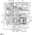
- in einer schematischen, geschnittenen Darstellung eine an einem Kupplungsgehäuse angeordnete Zusatzölpumpe und ein Achsdifferential,
- Fig. 2
- in einer schematischen, geschnitten Detaildarstellung die Zusatzölpumpe,
- Fig. 3
- in einer stark schematischen Darstellung ein Kraftfahrzeug mit einer Verbrennungskraftmaschine und mit einem Doppelkupplungsgetriebe,
- Fig. 4
- in einer schematischen Darstellung einen ersten Hydraulikkreislauf mit der Zusatzölpumpe und einer Hauptölpumpe, und
- Fig. 5
- in einer stark schematischen Darstellung einen weiteren Hydraulikkreislauf mit der Hauptölpumpe und der Zusatzölpumpe.
- In den
Fig. 1 undFig. 2 ist eine Ölpumpenanordnung 1 mit einer Zusatzölpumpe 2 für ein nicht näher dargestelltes Getriebe eines Kraftfahrzeugs zu erkennen. - Die Zusatzölpumpe 2 ist in einen Hydraulikkreislauf 26 oder 27 integriert (vgl.
Fig. 4 bzw. 5), wobei die Hydraulikkreisläufe 26, 27 jeweils eine Hauptölpumpe 28 aufweisen, wobei die Hauptölpumpe 28 parallel zu der Zusatzölpumpe 2 (mit dem entsprechenden Pumpenteil 3 und dem Pumpenmotor 4) angeordnet ist. Das Pumpenteil 3 ist insbesondere als Zahnradpumpe ausgebildet. Das Pumpenteil 3 kann als Gerotorpumpe, d.h. als Zahnringpumpe oder auch als Sichelpumpe ausgebildet sein. - Bevor auf die Hydraulikkreise 26, 27 näher eingegangen wird, darf jedoch zunächst die Anordnung und Ausbildung der Zusatzölpumpe 2 anhand der
Fig. 1 und2 erläutert werden:
Die Zusatzölpumpe 2 weist ein hydrostatisches Pumpenteil 3 und einen Pumpenmotor 4 auf. Das Pumpenteil 3 ist von dem Pumpenmotor 4 antreibbar und steht mit dem Pumpenmotor 4 in Wirkverbindung. Das Pumpenteil 3 und der Pumpenmotor 4 sind an einem Gehäuse 5 montiert. Das Gehäuse 5 ist als Kupplungsgehäuse 6 ausgebildet. Das Gehäuse 5 begrenzt einen Ölraum 7. - Die eingangs genannten Nachteile sind nun dadurch vermieden, dass das Pumpenteil 3 innerhalb des Gehäuses 5 und der Pumpenmotor 4 von außen am Gehäuse 5 montierbar ist. Das Gehäuse 5 weist eine Aufnahme 8 auf. Das Pumpenteil 3 wird von innen am Gehäuse 5 und der Pumpenmotor 4 mit einem Steuergerät 9 von außen in der Aufnahme 8 am Gehäuse 5 montiert. Die Antriebseinheit besteht aus dem Pumpenmotor 4 und dem Steuergerät 9 ist und für einen Kundendienst von außen zugänglich angeordnet und somit tauschbar.
- Das Gehäuse 5 weist eine Montagewand 10 auf. Die Montagewand 10 weist einen in die Aufnahme vorkragenden Sitz 11 auf. Der Pumpenmotor 4 ist an dem Sitz 11 zentriert. Der Sitz 11 umgibt einen Durchgriff 12. Ferner ist auf der anderen Seite der Montagewand 10 im Inneren das Pumpenteil 3 an dem Durchgriff 12 zentriert. Der Sitz 11 und der Durchgriff 12 sind zentral an der Montagewand 10 ausgebildet. Der Durchgriff 12 ist insbesondere zylindrisch ausgebildet und erstreckt sich koaxial zur nicht dargestellten virtuellen Pumpenachse der Zusatzölpumpe 2. Der Durchgriff 12 und der Sitz 11 ermöglichen eine gemeinsame Zentrierung des Pumpenteils 3 und des Pumpenmotors 4.
- Die Montagewand 10 weist Öffnungen 37 auf, so dass Öl in die Aufnahme 8 gelangen kann. Die Aufnahme 8 bildet daher auch einen Teil des Ölraums 7. Der Pumpenmotor 4 befindet sich innerhalb des Ölraums 7. Zwischen dem Pumpenmotor 4 und der Aufnahme 8 verbleibt ein Spalt 36. Hierdurch ist der Pumpenmotor 4 durch das entsprechende Öl (nicht dargestellt) am Außenumfang kühlbar.
- Es ist eine Zwischenwelle 13 vorgesehen (vgl.
Fig. 2 ), wobei die Zwischenwelle 13 das Pumpenteil 3 und den Pumpenmotor 4 durch den Durchgriff 12 miteinander verbindet. Die Zwischenwelle 13 ist verliersicher in das Pumpenteil 3 integriert. Die Leistungsübertragung zwischen dem Pumpenmotor 4 und dem Pumpenteil 3 erfolgt über eine Steckverzahnung bzw. ein Mehrkantprofil (nicht näher bezeichnet) oder alternativ über eine andere formschlüssige Verbindung. Die Zwischenwelle 13 ist vorzugsweise nicht fest gelagert und kann so Winkelfehler zwischen dem Pumpenmotor 4 und dem Pumpenteil 3 ähnlich einer Gelenkwelle ausgleichen. - Das Steuergerät 9 ist am Kopf 14 des Pumpenmotors 4 angeordnet. Das Steuergerät 9 ist insbesondere mit dem Pumpenmotor 4 verbunden. Vorzugsweise ist eine Schraubverbindung 15 (vgl.
Fig. 1 ) vorgesehen, die das Steuergerät 9 mit dem Pumpenmotor 4 verbindet. Das Steuergerät 9, insbesondere ein entsprechendes Gehäuse (nicht näher bezeichnet) des Steuergerätes 9 wird nun dazu verwendet, die Aufnahme 8 des Kupplungsgehäuses 6 gegenüber der Umgebung abzudichten. Das Steuergerät 9 ragt dazu zumindest teilweise in die Aufnahme 8 hinein und liegt an dem Innenumfang der Aufnahme 8 mittels entsprechender Dichtmittel 16 abdichtend an. Das Steuergerät 9 liegt im Gegensatz zum Pumpenmotor 4 teilweise außerhalb des Kupplungsgehäuses 6. Die Dichtmittel 16 können insbesondere als O-Ringe ausgebildet sein. Alternativ können als Dichtmittel 16 Formdichtringe oder ein Multi-Lip-Seal genutzt werden, um das Steuergerät 9 gegenüber der Aufnahme 8 abzudichten. Ferner ist eine antriebsinterne Ölabdichtung des Steuergeräts 9 gegenüber dem ölumströmten Pumpenmotor 4 vorgesehen. Hierzu können insbesondere stromtragende 3-Phasen-Leitungen durch einen Verguss gegenüber dem Pumpenmotor 4 abgedichtet sein. Es kann sich insbesondere um einen Glasverguss handeln. - Wie in
Fig. 1 gut zu erkennen ist, ist die Zusatzölpumpe 2 hier im Bereich eines Differentials 17 angeordnet. Das Differential 17 weist insbesondere zwei Achswellen 18, 19 auf, die über entsprechende Ausgleichsräder 20 in Wirkverbindung stehen. Die Ausgleichsräder 20 sind entsprechend drehbar an einem angetriebenen Ausgleichsgehäuse 21 gelagert. Das Pumpenteil 3 und der Pumpenmotor 4 sind in der Umgebung des Differentials 17 im bzw. am Kupplungsgehäuse 6 angeordnet. Die Achse dieses Systems bestehend aus dem Pumpenteil 3 und dem Pumpenmotor 4 liegt unterhalb der Mitte des Differentials 17 möglichst nah an einem nicht dargestellten Saugfilter. Diese Achse des Systems ist planparallel zu der entsprechenden Achse der Achswellen 18, 19. Es ist jedoch durchaus auch eine andersartige Ausrichtung der Achse der Zusatzölpumpe 2 möglich. - Der Bauraum des Pumpenteils 3 überschneidet sich mit tragenden Strukturen, nämlich einer entsprechenden Rippe, die an der Innenseite des Kupplungsgehäuse 6 ausgebildet ist. Das Pumpenteil 3 hat vorzugsweise eine tragende Funktion und überträgt entsprechende Lasten, ohne dass es zu einer Deformation im Radsatz (nicht näher bezeichnet) des Pumpenteils 3 kommt. Das Gehäuse 5 weist eine Rippe auf (nicht dargestellt), wobei die Rippe eine Aussparung im Bereich des Pumpenteils 3 aufweist, wobei das Pumpenteil 3 die Aussparung überbrückt und so die Versteifungsfunktion der Rippe in diesem Bereich übernimmt. Das Pumpenteil 3 weist ein Pumpengehäuse 38 auf. Das Pumpengehäuse 38 ist so gestaltet, dass die erforderliche Tragfunktion der Rippe durch das Pumpengehäuse 38 übernommen wird. Die Struktur ist dabei so gewählt, dass die zu übertragenden Lasten höchstens zu geringen Deformationen im Pumpengehäuse 38, nämlich des entsprechenden Radsatzes führen. Das Pumpengehäuse 38 wird über drei Schrauben mit dem Kupplungsgehäuse 6 verbunden. Der hydraulische Teil der Zusatzölpumpe 2 - nämlich das Pumpenteil 3 - ist von außen unzugänglich in den Getrieberaum integriert.
- Das Steuergerät 9 ist insbesondere gekrümmt bzw. "bananenförmig" ausgebildet und umgreift so den in
Fig. 1 rechten Bereich des Differentials 17 bogensegmentförmig. Das Steuergerät 9 ist hier im Bereich der Schnittstelle für den Vorderachsantrieb bzw. der Vorderachsquersperre angeordnet. Beim Verbau dieser Aggregate ist das Steuergerät 9 zwischen dem Gehäuse 22 des Vorderachsantriebes und des Gehäuses 5 angeordnet. Bei Allradfahrzeugen bzw. bei Fahrzeugen mit Quersperren findet kein stärkere Erwärmung statt. Sind diese Zusatzaggregate nicht verbaut, könnte das Steuergerät 9 der Wärme der Abgasanlage ausgesetzt sein. Es erfolgt hierbei eine Entwärmung des Steuergerätes 9 über eine massive Verschraubung mit dem Kupplungsgehäuse 6 oder in alternativer Bauform über einen flächigen Kontakt des Steuergerätes 9 mit dem Kupplungsgehäuse 6. Diese elektrisch angetriebene Zusatzölpumpe 2 ist im vorhandenen Bauraum in ein quer eingebautes Doppelkupplungsgetriebe DKG (vgl.Fig 3 ) integrierbar. Bei einer maximalen Leistungsaufnahme der Zusatzölpumpe 2 von 300 Watt sind insbesondere Kühlölmengen von bis zu 15 Liter pro Minute bereitstellbar. - In
Fig. 3 ist eine Verbrennungskraftmaschine VKM und ein Doppelkupplungsgetriebe DKG dargestellt. Das Doppelkupplungsgetriebe DKG wird von einem Getriebesteuergerät GSG gesteuert bzw. geregelt. Über einen Antriebs-CAN-Bus (CAN-Controller Area Network) ist das Getriebesteuergerät GSG mit einem Motorsteuergerät MSG verbunden. Über einen Getriebe-CAN-Bus ist das Getriebesteuergerät GSG mit dem Pumpensteuergerät 9/PSG verbunden. Das Pumpensteuergerät 9/PSG ist mit einer Strom- bzw. Spannungsversorgung 23 verbunden. Diese Spannungsversorgung 23 kann wie dargestellt mit 12 Volt arbeiten oder in alternativer Ausgestaltung beispielsweise 48 Volt bereitstellen. Die Spannungsversorgung 23 ist unabhängig von einer Spannungsversorgung des Getriebesteuergerätes GSG. Damit ist es für spätere Anwendungen leicht möglich die Zusatzölpumpe 2 beispielsweise von 12 Volt auf 48 Volt umzustellen ohne dabei das Getriebesteuergerät GSG ändern zu müssen. Der Pumpenmotor 4 wird als Aktor des Getriebesteuergerätes GSG betrieben und über den Getriebe-CAN-BUS mit Steuersignalen und Sollgrößen versorgt. - Die Zusatzölpumpe 2 ist in
Fig. 3 nicht näher dargestellt aber hier jedoch unterhalb des Differentials 17 angeordnet, wobei von dem Differential 17 die beiden Achswellen 18, 19 ausgehen und die entsprechenden Antriebsräder 24, 25 antreiben. Die Verbrennungskraftmaschine VKM und das Doppelkupplungsgetriebe sind im Frontbereich des Kraftfahrzeugs quer eingebaut. - Im Folgenden darf nun auf die zwei Hydraulikkreisläufe 26, 27 anhand der
Fig. 4 und5 eingegangen werden: - Die Hydraulikkreisläufe 26, 27 weisen jeweils zunächst eine Hauptölpumpe 28 auf, wobei die Hauptölpumpe 28 jeweils parallel zu der Zusatzölpumpe 2 mit dem entsprechenden Pumpenteil 3 und dem Pumpenmotor 4 angeordnet ist. Die Hauptölpumpe 28 wie auch die Zusatzölpumpe 2 fördern über einen Saugfilter 29 entsprechendes Getriebeöl aus einem Getriebeölsumpf 30.
- Die Hauptölpumpe 28 versorgt eine Mechatronikeinheit 31. Von der Mechatronikeinheit 31 werden entsprechende Aktuatoren 32 oder auch die Kupplung 33 mit Drucköl versorgt. Ferner wird über die Mechatronikeinheit 31 dem Getriebe Kühlöl bzw. Schmieröl zugeführt, wie es durch die beiden Zahnritzel links in den Abbildungen 4 und 5 dargestellt ist. Die Zusatzölpumpe 2 fördert nun parallel zu der Hauptölpumpe 28 ebenfalls entsprechendes Öl zur Mechatronikeinheit 31. Hierbei ist zwischen der Mechatronikeinheit 31 und der Zusatzölpumpe 2 ein Rückschlagventil 34 vorgesehen. Das Rückschlagventil 34 ist in einer Ausgestaltung innerhalb des Gehäuses 5 angeordnet. Alternativ kann das Rückschlagventil 34 in die Mechatronikeinheit 31 integriert sein.
- Ferner ist ein Rückschlagventil 39 stromabwärts der Hauptölpumpe 28 angeordnet. Wenn nur die Zusatzölpumpe 2 und nicht die Hauptölpumpe 28 fördert, dann sperrt das Rückschlagventil 39 den Förderstrom der Zusatzölpumpe 2 gegen die Hauptölpumpe 28 ab, so dass der Förderstrom in die Mechatronik 31 geleitet wird. Die Durchströmung der Hauptölpumpe 28 entgegen der Förderrichtung ist durch das Rückschlagventil 39 unterbunden. Das Rückschlagventil 39 ist in einer Ausgestaltung innerhalb des Gehäuses 5 angeordnet. Das Rückschlagventil 39 kann in die Hauptölpumpe 39 integriert sein. Alternativ kann das Rückschlagventil 39 in die Mechatronikeinheit 31 integriert sein.
- In der in
Fig. 5 dargestellten Ausgestaltung ist die Hauptölpumpe 28 verstellbar. Dies stellt sicher, dass auch bei niedrigen Drehzahlen der Verbrennungskraftmaschine VKM noch hinreichend Kühlöl zur Verfügung steht. In der inFig. 4 dargestellten Ausgestaltung ist die Hauptölpumpe 28 als Konstantpumpe ausgestaltet. Es ist nun ein Ventil 35 stromabwärts der Zusatzölpumpe 2 zwischen der Zusatzölpumpe 2 und dem Rückschlagventil 34 angeordnet. Mittels dieses Ventils 35 ist es möglich, Kühlöl unterhalb des Hauptdrucks bereitzustellen. Die Ansteuerung des Ventils 35 kann über ein elektrisches Vorsteuerventil in der Mechatronikeinheit 31 erfolgen. Alternativ kann das Ventil 35 direkt gesteuert sein. Das Ventil 35 kann innerhalb des Gehäuses 5 angeordnet sein. Das Ventil 35 kann in alternativer Ausgestaltung in die Mechatronikeinheit 31 integriert sein. Die Hauptölumpe 28 ist als Konstantölpumpe ausgebildet und weist ein großes Hubvolumen auf. So ist in jeder Betriebssituation eine hinreichende Ölversorgung gewährleistet. - Insbesondere weist das Kraftfahrzeug eine Start-Stopp-Automatik auf. Da die Hauptölpumpe 28 bei stehendem Verbrennungsmotor nicht fördert, ist nun die Zusatzölpumpe 2 vorgesehen. Hierdurch ist insbesondere eine Start-Stopp-Automatik auch bei mehr als 2 km pro Stunde und ein Segeln des Kraftfahrzeugs mit ausgestellter Verbrennungskraftmaschine VKM darstellbar. Durch die Anordnung der Zusatzölpumpe 2 ist das System robust. Ferner ist durch die Zusatzölpumpe 2 auch bei längeren Standzeiten und der Start-Stopp-Automatik gewährleistet, dass der Systemdruck hinreichend schnell aufgebaut werden kann. Des Weiteren kann durch die Zusatzölpumpe 2 der Gesamtwirkungsgrad im Antriebsstrang gesteigert werden. Insbesondere lassen sich Verluste durch die Bereitstellung hydraulischer Hilfsenergien für die Aktivierung sowie zu Kühl- und Schmierzwecken verringern. In die entsprechenden Hydraulikkreisläufe 26, 27 ist kein zusätzlicher hydraulischer Speicher integriert. Die Hauptölpumpe 28 kann beispielsweise kleiner ausgelegt werden, da Extremsituationen durch Zuschalten der Zusatzölpumpe 2 kompensiert werden können. Insbesondere lassen sich mit der vorgestellten Zusatzölpumpe 2 Start-Stopp-Funktionalitäten auch schon bei höheren Geschwindigkeiten von zum Beispiel 7 km/h oder ein Segeln des Kraftfahrzeugs mit ausgestellter Verbrennungskraftmaschine VKM bereitstellen. Durch die Zusatzölpumpe 2 kann auch bei stehendem Kraftfahrzeug hydraulische Energie in Form einer Druckölversorgung oder einer Schmierölversorgung bereitgestellt sein.
- Die Hauptölpumpe 28 kann als Flügelzellenpumpe ausgebildet sein. Die Zusatzölpumpe 2 kann nun dazu eingesetzt werden, Ansaugschwierigkeiten der Flügelzellenpumpe bzw. der Hauptölpumpe 28 zu vermeiden. Beispielsweise kann ein Aufladen der Hauptölpumpe 28 durch die Zusatzölpumpe 2 erfolgen, wobei die Mechatronikeinheit 31 über eine zusätzliche Versorgungsleitung 40 mit dem Ansaugtrakt der Hauptölpumpe 28 verbunden ist. Die Versorgungsleitung 40 mündet vorzugsweise in eine Saugniere (nicht dargestellt) der Hauptölpumpe 28. Vorzugsweise ist mittels der Mechatronikeinheit 31 die Versorgungsleitung 40 schaltbar. Das Aufladen der Hauptölpumpe 28 ist hierbei durch die Mechatronikeinheit 31 bereitgestellt. Wenn kein Drucköl und kein Kühlölvolumenstrom angefordert werden, fließt abgesehen von den auftretenden Systemleckagen, der gesamte Ölvolumenstrom der Zusatzpumpe 2 über die zusätzliche Versorgungsleitung 40 in den Ansaugtrackt der Hauptölpumpe 28. Im ölbefüllten Zustand des Ansaugtracktes der Hauptölpumpe 28 treten dann keine Ansaugschwierigkeiten auf.
-
- 1
- Ölpumpenanordnung
- 2
- Zusatzölpumpe
- 3
- Pumpenteil
- 4
- Pumpenmotor
- 5
- Gehäuse
- 6
- Kupplungsgehäuse
- 7
- Ölraum
- 8
- Aufnahme
- 9
- Steuergerät
- 10
- Montagewand
- 11
- Sitz
- 12
- Durchgriff
- 13
- Zwischenwelle
- 14
- Kopf
- 15
- Schraubverbindung
- 16
- Dichtmittel
- 17
- Differential
- 18
- Achswelle
- 19
- Achswelle
- 20
- Ausgleichsrad
- 21
- Ausgleichsgehäuse
- 22
- Gehäuse (Vorderradachsantrieb)
- 23
- Spannungsversorgung
- 24
- Antriebsrad
- 25
- Antriebsrad
- 26
- Hydraulikkreislauf
- 27
- Hydraulikkreislauf
- 28
- Hauptölpumpe
- 29
- Saugfilter
- 30
- Getriebeölsumpf
- 31
- Mechatronikeinheit
- 32
- Aktuator
- 33
- Kupplung
- 34
- Rückschlagventil
- 35
- Ventil
- 36
- Spalt
- 37
- Öffnungen
- 38
- Pumpengehäuse
- 39
- Rückschlagventil
- 40
- Versorgungsleitung
- VKM
- Verbrennungskraftmaschine
- DKG
- Doppelkupplungsgetriebe
- GSG
- Getriebesteuergerät
- PSG
- Pumpensteuergerät
- MSG
- Motorsteuergerät
Claims (10)
- Ölpumpenanordnung (1) eines Kraftfahrzeuggetriebes, mit einer Ölpumpe (2), die ein Pumpenteil (3) und einen elektrischen Pumpenmotor (4) aufweist, wobei das Pumpenteil (3) in Wirkverbindung mit dem Pumpenmotor (4) steht, wobei das Pumpenteil (3) und/oder der Pumpenmotor (4) an einem Gehäuse (5) montiert ist, wobei das Gehäuse (5) einen Ölraum (7) zumindest teilweise begrenzt, wobei das Pumpenteil (3) innerhalb des Gehäuses (5) und der Pumpenmotor (4) von außen am Gehäuse (5) montiert ist, wobei eine Zwischenwelle (13) vorhanden ist, wobei die Zwischenwelle (13) das Pumpenteil (3) und den Pumpenmotor (4) miteinander verbindet, wobei das Gehäuse (5) eine Aufnahme (8) aufweist, wobei der Pumpenmotor (4) zumindest teilweise in die Aufnahme (8) eingreift, wobei das Gehäuse (5) eine die Aufnahme (8) begrenzende Montagewand (10) aufweist, wobei die Montagewand (10) einen Durchgriff (12) aufweist, wobei das Pumpenteil (3) innen an der Montagewand (10) zentriert ist und der Pumpenmotor (4) außen an der Montagewand (10) zentriert ist, wobei die Zwischenwelle (13) das Pumpenteil (3) und den Pumpenmotor (4) durch den Durchgriff (12) miteinander verbindet, wobei das Gehäuse (5) als Kupplungsgehäuse (6) ausgebildet ist, dadurch gekennzeichnet, dass am Pumpenmotor (4) ein Steuergerät (9) angeordnet ist, wobei das Steuergerät (9) gegenüber dem Pumpenmotor (4) abgedichtet ist, wobei das Steuergerät (9) gegenüber der Aufnahme (8) mittels mindestens eines Dichtmittels (16) abgedichtet ist, wobei das Steuergerät (9) zumindest teilweise außerhalb der Aufnahme (8) und damit auch außerhalb des Kupplungsgehäuses (6) liegt, wobei die Montagewand (10) Öffnungen aufweist, so dass Öl in die Aufnahme (8) gelangen kann, wobei die Aufnahme (8) einen Teil des Ölraums (7) bildet, wobei der Pumpenmotor (4) sich innerhalb des Ölraums (7) befindet, wobei zwischen dem Pumpenmotor (4) und der Aufnahme (8) ein Spalt (36) verbleibt, wobei der Pumpenmotor (4) durch das Öl am Außenumfang kühlbar ist.
- Olpumpenanordnung nach Anspruch 1, dadurch gekennzeichnet, dass die Ölpumpe (2) im Bereich eines Differentials (17) des Kraftfahrzeuggetriebes angeordnet ist.
- Olpumpenanordnung nach einem der vorstehenden Ansprüche, dadurch gekennzeichnet, dass das Pumpenteil (3) und der Pumpenmotor (4) über eine gelenkig angeordnete Zwischenwelle (13) verbunden sind.
- Ölpumpenanordnung nach einem der vorstehenden Ansprüche, dadurch gekennzeichnet, dass das Pumpenteil (3) mit dem Gehäuse (5) verschraubt ist, wobei das Pumpenteil (3) eine Versteifungsfunktion des Gehäuses (5) übernimmt.
- Ölpumpenanordnung nach dem vorstehenden Anspruch, dadurch gekennzeichnet, dass das Gehäuse (5) eine Rippe aufweist, wobei die Rippe eine Aussparung im Bereich des Pumpenteils (3) aufweist, wobei das Pumpenteil (3) die Aussparung überbrückt.
- Ölpumpenanordnung nach einem der vorstehenden Ansprüche, dadurch gekennzeichnet, dass sie eine von einer Verbrennungskraftmaschine (VKM) funktional wirksam angetriebene Hauptölpumpe (28) aufweist, die in einem Hydraulikkreislauf (26, 27) parallel zur Ölpumpe (2) angeordnet ist.
- Ölpumpenanordnung nach einem der vorstehenden Ansprüche, dadurch gekennzeichnet, dass ein Umschaltventil stromabwärts der Ölpumpe (2) vorgesehen ist, wobei in einer Schaltstellung des Umschaltventils die Ölpumpe (2) eine Mechatronik speist und in einer anderen Schaltstellung einen Kühlölzweig speist.
- Olpumpenanordnung nach einem der vorstehenden Ansprüche, dadurch gekennzeichnet, dass eine Zusatzölpumpe (2) eine von einem Getriebesteuergerät (GSG) unabhängige elektrische Spannungsversorgung (23) aufweist.
- Ölpumpenanordnung nach Anspruch 6, dadurch gekennzeichnet, dass ein Ansaugtrakt der Hauptölpumpe (28) durch die Ölpumpe (2) aufladbar ist.
- Ölpumpenanordnung nach einem der vorstehenden Ansprüche, dadurch gekennzeichnet, dass das Kupplungsgehäuse (6) einen Teil eines Getriebegehäuses bildet und/oder ein Getriebegehäuse zumindest teilweise abdichtet.
Applications Claiming Priority (2)
| Application Number | Priority Date | Filing Date | Title |
|---|---|---|---|
| DE102015200317.5A DE102015200317A1 (de) | 2015-01-13 | 2015-01-13 | Ölpumpenanordnung für ein Kraftfahrzeug |
| PCT/EP2016/000047 WO2016113133A1 (de) | 2015-01-13 | 2016-01-13 | Ölpumpenanordnung für ein kraftfahrzeug |
Publications (2)
| Publication Number | Publication Date |
|---|---|
| EP3245426A1 EP3245426A1 (de) | 2017-11-22 |
| EP3245426B1 true EP3245426B1 (de) | 2021-05-19 |
Family
ID=55963279
Family Applications (1)
| Application Number | Title | Priority Date | Filing Date |
|---|---|---|---|
| EP16721628.2A Active EP3245426B1 (de) | 2015-01-13 | 2016-01-13 | Ölpumpenanordnung für ein kraftfahrzeug |
Country Status (6)
| Country | Link |
|---|---|
| US (1) | US10598271B2 (de) |
| EP (1) | EP3245426B1 (de) |
| KR (1) | KR102057569B1 (de) |
| CN (1) | CN107110333B (de) |
| DE (1) | DE102015200317A1 (de) |
| WO (1) | WO2016113133A1 (de) |
Families Citing this family (6)
| Publication number | Priority date | Publication date | Assignee | Title |
|---|---|---|---|---|
| US10208853B2 (en) * | 2015-02-27 | 2019-02-19 | Brose Fahrzeugteile Gmbh & Co. Kommanditgesellschaft, Wuerzburg | Motor assembly |
| CN112303209B (zh) * | 2020-10-30 | 2022-08-09 | 重庆长安汽车股份有限公司 | 一种dct变速器电子油泵布置结构及车辆 |
| US11525506B2 (en) * | 2021-02-09 | 2022-12-13 | GM Global Technology Operations LLC | Transfer case off-axis pump |
| DE102021110123B4 (de) | 2021-04-21 | 2023-03-09 | Dr. Ing. H.C. F. Porsche Aktiengesellschaft | Pumpenanordnung |
| WO2023182450A1 (ja) * | 2022-03-23 | 2023-09-28 | ジヤトコ株式会社 | 動力伝達装置 |
| DE102022109970A1 (de) * | 2022-04-26 | 2023-10-26 | Audi Aktiengesellschaft | Getriebemotor für ein Kraftfahrzeug und Kraftfahrzeug mit einem Getriebemotor |
Citations (4)
| Publication number | Priority date | Publication date | Assignee | Title |
|---|---|---|---|---|
| DE102007041584A1 (de) * | 2007-09-01 | 2009-03-05 | Zf Friedrichshafen Ag | Anordnung einer elektrisch betriebenen Ölpumpe eines Automatgetriebes |
| US20120128513A1 (en) * | 2009-08-04 | 2012-05-24 | Jtekt Corporation | Electric pump unit |
| DE112010005177T5 (de) * | 2010-01-25 | 2012-10-31 | Honda Motor Co., Ltd. | Leistungsübertragungsvorrichtung |
| JP2014009676A (ja) * | 2012-07-03 | 2014-01-20 | Jtekt Corp | 電動オイルポンプ装置 |
Family Cites Families (19)
| Publication number | Priority date | Publication date | Assignee | Title |
|---|---|---|---|---|
| JPH02252988A (ja) * | 1988-12-02 | 1990-10-11 | Jidosha Kiki Co Ltd | オイルポンプ |
| JP3343660B2 (ja) * | 1992-12-10 | 2002-11-11 | 本田技研工業株式会社 | オイルポンプ駆動装置 |
| JP2005299592A (ja) * | 2004-04-15 | 2005-10-27 | Toyota Motor Corp | 内燃機関の潤滑装置 |
| US7494439B2 (en) * | 2004-08-26 | 2009-02-24 | Gm Global Technology Operations, Inc. | Dual drive pump with dual chain and roller clutch and method |
| DE102005013657A1 (de) * | 2005-03-24 | 2006-09-28 | Volkswagen Ag | Zahnradgetriebe eines Kraftfahrzeugs und Verfahren zur Steuerung der Ölversorgungseinrichtung eines Zahnradgetriebes |
| DE102006012838A1 (de) * | 2005-05-11 | 2006-11-23 | Zf Friedrichshafen Ag | Automatgetriebe eines Kraftfahrzeuges |
| DE102007018504B4 (de) | 2007-04-19 | 2016-11-17 | Zf Friedrichshafen Ag | Kühl- und Schmiermittelversorgungssystem eines Getriebes |
| JP2008286108A (ja) * | 2007-05-17 | 2008-11-27 | Jtekt Corp | 車両用オイルポンプシステム |
| US8049384B2 (en) * | 2009-06-19 | 2011-11-01 | GM Global Technology Operations LLC | Electronic drive unit |
| JP5372649B2 (ja) * | 2009-08-05 | 2013-12-18 | 日立オートモティブシステムズ株式会社 | 電動ポンプ |
| JP4873058B2 (ja) | 2009-09-28 | 2012-02-08 | マツダ株式会社 | 車両用自動変速機 |
| DE102010002014A1 (de) * | 2010-02-17 | 2011-08-18 | ZF Friedrichshafen AG, 88046 | Antriebsanordnung für eine Ölpumpe in einem Getriebe eines Fahrzeuges |
| DE102011102789A1 (de) * | 2011-03-08 | 2012-09-13 | Getrag Getriebe- Und Zahnradfabrik Hermann Hagenmeyer Gmbh & Co. Kg | Hybrid-Antriebsstrang |
| DE102011086276A1 (de) * | 2011-11-14 | 2013-05-16 | Zf Friedrichshafen Ag | Anordnung zur Schmierölversorgung des Kettentriebs zum Antreiben einer achsversetzt zum Drehmomentwandler angeordneten Getriebeölpumpe bei einem Kraftfahrzeug mit einem Drehmomentwandler |
| JP5986021B2 (ja) * | 2013-03-18 | 2016-09-06 | 日立オートモティブシステムズ株式会社 | 電動モータおよび電動オイルポンプ |
| CN105518346B (zh) * | 2013-09-30 | 2017-11-14 | 爱信艾达株式会社 | 车辆用驱动装置 |
| CN204186976U (zh) * | 2014-11-04 | 2015-03-04 | 株洲齿轮有限责任公司 | 一种双油泵分动箱 |
| US20160160713A1 (en) * | 2014-12-04 | 2016-06-09 | Magna Powertrain Of America, Inc. | Lubrication system for power transfer unit having externally-mounted electric oil pump |
| EP3460294B1 (de) * | 2017-09-20 | 2020-03-25 | Flender GmbH | Getriebe mit ölkühlung |
-
2015
- 2015-01-13 DE DE102015200317.5A patent/DE102015200317A1/de not_active Withdrawn
-
2016
- 2016-01-13 KR KR1020177022634A patent/KR102057569B1/ko active Active
- 2016-01-13 EP EP16721628.2A patent/EP3245426B1/de active Active
- 2016-01-13 CN CN201680005762.8A patent/CN107110333B/zh active Active
- 2016-01-13 WO PCT/EP2016/000047 patent/WO2016113133A1/de not_active Ceased
-
2017
- 2017-06-30 US US15/638,645 patent/US10598271B2/en active Active
Patent Citations (4)
| Publication number | Priority date | Publication date | Assignee | Title |
|---|---|---|---|---|
| DE102007041584A1 (de) * | 2007-09-01 | 2009-03-05 | Zf Friedrichshafen Ag | Anordnung einer elektrisch betriebenen Ölpumpe eines Automatgetriebes |
| US20120128513A1 (en) * | 2009-08-04 | 2012-05-24 | Jtekt Corporation | Electric pump unit |
| DE112010005177T5 (de) * | 2010-01-25 | 2012-10-31 | Honda Motor Co., Ltd. | Leistungsübertragungsvorrichtung |
| JP2014009676A (ja) * | 2012-07-03 | 2014-01-20 | Jtekt Corp | 電動オイルポンプ装置 |
Also Published As
| Publication number | Publication date |
|---|---|
| DE102015200317A1 (de) | 2016-07-14 |
| US20170299047A1 (en) | 2017-10-19 |
| CN107110333A (zh) | 2017-08-29 |
| EP3245426A1 (de) | 2017-11-22 |
| US10598271B2 (en) | 2020-03-24 |
| CN107110333B (zh) | 2020-10-16 |
| KR102057569B1 (ko) | 2020-01-14 |
| WO2016113133A1 (de) | 2016-07-21 |
| KR20170106393A (ko) | 2017-09-20 |
Similar Documents
| Publication | Publication Date | Title |
|---|---|---|
| EP3245426B1 (de) | Ölpumpenanordnung für ein kraftfahrzeug | |
| DE10207653C1 (de) | Elektrische Kühlmittelpumpe mit integriertem Ventil, sowie Verfahren zu dessen Steuerung | |
| EP2667053B1 (de) | Kühlanordnung und Kühlverfahren für KFZ-Antriebsstrang | |
| DE102009015319B4 (de) | Antriebsstrang für ein Fahrzeug sowie Hydrauliksystem für ein Getriebe | |
| EP2383491B1 (de) | Getriebe mit Schmierölpumpe, Getriebe-Baureihe und Verfahren zum Herstellen von Varianten einer Getriebe-Baureihe | |
| EP3093533A2 (de) | Kraftfahrzeug-antriebsstrang und verfahren zu dessen betreiben | |
| EP2516860B1 (de) | Hydrauliksteuerung | |
| DE112010003517T5 (de) | Antriebsvorrichtung | |
| WO2020207537A1 (de) | Elektrischer antrieb mit wärmetauscherabschnitt | |
| DE102008033434A1 (de) | Fahrzeug-Antriebsstrang mit Direkt-Leistungsentnahme-Stelle | |
| EP3371423B1 (de) | Fördereinrichtung zur förderung von öl | |
| EP4433725B1 (de) | Antriebsvorrichtung für eine elektrifizierte fahrzeugachse | |
| DE102019101957B4 (de) | Hydrauliksystem zur Steuerung eines Antriebsstrangs eines Kraftfahrzeugs | |
| DE10251042A1 (de) | Kraftfahrzeug-Antriebsvorrichtung | |
| EP3380757B1 (de) | Pumpenanordnung und hydraulikanordnung für kraftfahrzeug-antriebsstrang | |
| EP3614022B1 (de) | Hybridgetriebe | |
| DE102015115841B4 (de) | Pumpen-Motor-Einheit mit einer Kühlung eines die Pumpe antreibenden Elektromotors mittels Leckagefluid | |
| DE102017201152A1 (de) | Hydraulikpumpe | |
| DE102011122878B4 (de) | Vorrichtung zur elektrofluidischen Versorgung oder Betätigung eines Bauteils eines Antriebsstranges | |
| EP3850245B1 (de) | Automatgetriebe mit retarder | |
| DE112014003790B4 (de) | Pumpeneinheit für eine Zapfwelle, Zapfwelle für ein Zapfwellenmodul und ein Fahrzeug mit einer Zapfwelle | |
| DE102023101253A1 (de) | Elektroantriebsanordnung mit Kühlung | |
| DE102004023631A1 (de) | Antrieb für Mobilfahrzeuge | |
| DE102015219725A1 (de) | Verfahren zum Betreiben einer Schmiermittelpumpe in einem Getriebe für ein Fahrzeug | |
| DE102020122260A1 (de) | Pumpenaggregat, insbesondere für ein Getriebe im Antriebsstrang eines Kraftfahrzeugs |
Legal Events
| Date | Code | Title | Description |
|---|---|---|---|
| STAA | Information on the status of an ep patent application or granted ep patent |
Free format text: STATUS: THE INTERNATIONAL PUBLICATION HAS BEEN MADE |
|
| PUAI | Public reference made under article 153(3) epc to a published international application that has entered the european phase |
Free format text: ORIGINAL CODE: 0009012 |
|
| STAA | Information on the status of an ep patent application or granted ep patent |
Free format text: STATUS: REQUEST FOR EXAMINATION WAS MADE |
|
| 17P | Request for examination filed |
Effective date: 20170814 |
|
| AK | Designated contracting states |
Kind code of ref document: A1 Designated state(s): AL AT BE BG CH CY CZ DE DK EE ES FI FR GB GR HR HU IE IS IT LI LT LU LV MC MK MT NL NO PL PT RO RS SE SI SK SM TR |
|
| AX | Request for extension of the european patent |
Extension state: BA ME |
|
| RIN1 | Information on inventor provided before grant (corrected) |
Inventor name: TAGGE, HOLGER Inventor name: WOEHL-BRUHN, HENNING Inventor name: MUELLER, FRANK Inventor name: WARNECKE, RAIMAR Inventor name: MORTHORST, BERND Inventor name: BIRNBAUM, THOMAS Inventor name: SPRENGER, RALF Inventor name: KNOLL, WALDEMAR Inventor name: CORNELSEN, KARSTEN |
|
| DAV | Request for validation of the european patent (deleted) | ||
| DAX | Request for extension of the european patent (deleted) | ||
| STAA | Information on the status of an ep patent application or granted ep patent |
Free format text: STATUS: EXAMINATION IS IN PROGRESS |
|
| 17Q | First examination report despatched |
Effective date: 20180508 |
|
| GRAP | Despatch of communication of intention to grant a patent |
Free format text: ORIGINAL CODE: EPIDOSNIGR1 |
|
| STAA | Information on the status of an ep patent application or granted ep patent |
Free format text: STATUS: GRANT OF PATENT IS INTENDED |
|
| INTG | Intention to grant announced |
Effective date: 20201204 |
|
| GRAS | Grant fee paid |
Free format text: ORIGINAL CODE: EPIDOSNIGR3 |
|
| GRAA | (expected) grant |
Free format text: ORIGINAL CODE: 0009210 |
|
| STAA | Information on the status of an ep patent application or granted ep patent |
Free format text: STATUS: THE PATENT HAS BEEN GRANTED |
|
| AK | Designated contracting states |
Kind code of ref document: B1 Designated state(s): AL AT BE BG CH CY CZ DE DK EE ES FI FR GB GR HR HU IE IS IT LI LT LU LV MC MK MT NL NO PL PT RO RS SE SI SK SM TR |
|
| REG | Reference to a national code |
Ref country code: GB Ref legal event code: FG4D Free format text: NOT ENGLISH |
|
| REG | Reference to a national code |
Ref country code: CH Ref legal event code: EP |
|
| REG | Reference to a national code |
Ref country code: DE Ref legal event code: R096 Ref document number: 502016013065 Country of ref document: DE |
|
| REG | Reference to a national code |
Ref country code: AT Ref legal event code: REF Ref document number: 1394277 Country of ref document: AT Kind code of ref document: T Effective date: 20210615 |
|
| REG | Reference to a national code |
Ref country code: IE Ref legal event code: FG4D Free format text: LANGUAGE OF EP DOCUMENT: GERMAN |
|
| REG | Reference to a national code |
Ref country code: LT Ref legal event code: MG9D |
|
| REG | Reference to a national code |
Ref country code: NL Ref legal event code: MP Effective date: 20210519 |
|
| PG25 | Lapsed in a contracting state [announced via postgrant information from national office to epo] |
Ref country code: FI Free format text: LAPSE BECAUSE OF FAILURE TO SUBMIT A TRANSLATION OF THE DESCRIPTION OR TO PAY THE FEE WITHIN THE PRESCRIBED TIME-LIMIT Effective date: 20210519 Ref country code: LT Free format text: LAPSE BECAUSE OF FAILURE TO SUBMIT A TRANSLATION OF THE DESCRIPTION OR TO PAY THE FEE WITHIN THE PRESCRIBED TIME-LIMIT Effective date: 20210519 Ref country code: BG Free format text: LAPSE BECAUSE OF FAILURE TO SUBMIT A TRANSLATION OF THE DESCRIPTION OR TO PAY THE FEE WITHIN THE PRESCRIBED TIME-LIMIT Effective date: 20210819 Ref country code: HR Free format text: LAPSE BECAUSE OF FAILURE TO SUBMIT A TRANSLATION OF THE DESCRIPTION OR TO PAY THE FEE WITHIN THE PRESCRIBED TIME-LIMIT Effective date: 20210519 |
|
| PG25 | Lapsed in a contracting state [announced via postgrant information from national office to epo] |
Ref country code: GR Free format text: LAPSE BECAUSE OF FAILURE TO SUBMIT A TRANSLATION OF THE DESCRIPTION OR TO PAY THE FEE WITHIN THE PRESCRIBED TIME-LIMIT Effective date: 20210820 Ref country code: IS Free format text: LAPSE BECAUSE OF FAILURE TO SUBMIT A TRANSLATION OF THE DESCRIPTION OR TO PAY THE FEE WITHIN THE PRESCRIBED TIME-LIMIT Effective date: 20210919 Ref country code: LV Free format text: LAPSE BECAUSE OF FAILURE TO SUBMIT A TRANSLATION OF THE DESCRIPTION OR TO PAY THE FEE WITHIN THE PRESCRIBED TIME-LIMIT Effective date: 20210519 Ref country code: PL Free format text: LAPSE BECAUSE OF FAILURE TO SUBMIT A TRANSLATION OF THE DESCRIPTION OR TO PAY THE FEE WITHIN THE PRESCRIBED TIME-LIMIT Effective date: 20210519 Ref country code: NO Free format text: LAPSE BECAUSE OF FAILURE TO SUBMIT A TRANSLATION OF THE DESCRIPTION OR TO PAY THE FEE WITHIN THE PRESCRIBED TIME-LIMIT Effective date: 20210819 Ref country code: PT Free format text: LAPSE BECAUSE OF FAILURE TO SUBMIT A TRANSLATION OF THE DESCRIPTION OR TO PAY THE FEE WITHIN THE PRESCRIBED TIME-LIMIT Effective date: 20210920 Ref country code: RS Free format text: LAPSE BECAUSE OF FAILURE TO SUBMIT A TRANSLATION OF THE DESCRIPTION OR TO PAY THE FEE WITHIN THE PRESCRIBED TIME-LIMIT Effective date: 20210519 Ref country code: SE Free format text: LAPSE BECAUSE OF FAILURE TO SUBMIT A TRANSLATION OF THE DESCRIPTION OR TO PAY THE FEE WITHIN THE PRESCRIBED TIME-LIMIT Effective date: 20210519 |
|
| PG25 | Lapsed in a contracting state [announced via postgrant information from national office to epo] |
Ref country code: NL Free format text: LAPSE BECAUSE OF FAILURE TO SUBMIT A TRANSLATION OF THE DESCRIPTION OR TO PAY THE FEE WITHIN THE PRESCRIBED TIME-LIMIT Effective date: 20210519 |
|
| PG25 | Lapsed in a contracting state [announced via postgrant information from national office to epo] |
Ref country code: ES Free format text: LAPSE BECAUSE OF FAILURE TO SUBMIT A TRANSLATION OF THE DESCRIPTION OR TO PAY THE FEE WITHIN THE PRESCRIBED TIME-LIMIT Effective date: 20210519 Ref country code: RO Free format text: LAPSE BECAUSE OF FAILURE TO SUBMIT A TRANSLATION OF THE DESCRIPTION OR TO PAY THE FEE WITHIN THE PRESCRIBED TIME-LIMIT Effective date: 20210519 Ref country code: EE Free format text: LAPSE BECAUSE OF FAILURE TO SUBMIT A TRANSLATION OF THE DESCRIPTION OR TO PAY THE FEE WITHIN THE PRESCRIBED TIME-LIMIT Effective date: 20210519 Ref country code: CZ Free format text: LAPSE BECAUSE OF FAILURE TO SUBMIT A TRANSLATION OF THE DESCRIPTION OR TO PAY THE FEE WITHIN THE PRESCRIBED TIME-LIMIT Effective date: 20210519 Ref country code: DK Free format text: LAPSE BECAUSE OF FAILURE TO SUBMIT A TRANSLATION OF THE DESCRIPTION OR TO PAY THE FEE WITHIN THE PRESCRIBED TIME-LIMIT Effective date: 20210519 Ref country code: SK Free format text: LAPSE BECAUSE OF FAILURE TO SUBMIT A TRANSLATION OF THE DESCRIPTION OR TO PAY THE FEE WITHIN THE PRESCRIBED TIME-LIMIT Effective date: 20210519 Ref country code: SM Free format text: LAPSE BECAUSE OF FAILURE TO SUBMIT A TRANSLATION OF THE DESCRIPTION OR TO PAY THE FEE WITHIN THE PRESCRIBED TIME-LIMIT Effective date: 20210519 |
|
| REG | Reference to a national code |
Ref country code: DE Ref legal event code: R097 Ref document number: 502016013065 Country of ref document: DE |
|
| PLBE | No opposition filed within time limit |
Free format text: ORIGINAL CODE: 0009261 |
|
| STAA | Information on the status of an ep patent application or granted ep patent |
Free format text: STATUS: NO OPPOSITION FILED WITHIN TIME LIMIT |
|
| 26N | No opposition filed |
Effective date: 20220222 |
|
| PG25 | Lapsed in a contracting state [announced via postgrant information from national office to epo] |
Ref country code: IS Free format text: LAPSE BECAUSE OF FAILURE TO SUBMIT A TRANSLATION OF THE DESCRIPTION OR TO PAY THE FEE WITHIN THE PRESCRIBED TIME-LIMIT Effective date: 20210919 Ref country code: AL Free format text: LAPSE BECAUSE OF FAILURE TO SUBMIT A TRANSLATION OF THE DESCRIPTION OR TO PAY THE FEE WITHIN THE PRESCRIBED TIME-LIMIT Effective date: 20210519 |
|
| PG25 | Lapsed in a contracting state [announced via postgrant information from national office to epo] |
Ref country code: IT Free format text: LAPSE BECAUSE OF FAILURE TO SUBMIT A TRANSLATION OF THE DESCRIPTION OR TO PAY THE FEE WITHIN THE PRESCRIBED TIME-LIMIT Effective date: 20210519 |
|
| PG25 | Lapsed in a contracting state [announced via postgrant information from national office to epo] |
Ref country code: MC Free format text: LAPSE BECAUSE OF FAILURE TO SUBMIT A TRANSLATION OF THE DESCRIPTION OR TO PAY THE FEE WITHIN THE PRESCRIBED TIME-LIMIT Effective date: 20210519 |
|
| REG | Reference to a national code |
Ref country code: CH Ref legal event code: PL |
|
| REG | Reference to a national code |
Ref country code: BE Ref legal event code: MM Effective date: 20220131 |
|
| PG25 | Lapsed in a contracting state [announced via postgrant information from national office to epo] |
Ref country code: LU Free format text: LAPSE BECAUSE OF NON-PAYMENT OF DUE FEES Effective date: 20220113 |
|
| PG25 | Lapsed in a contracting state [announced via postgrant information from national office to epo] |
Ref country code: BE Free format text: LAPSE BECAUSE OF NON-PAYMENT OF DUE FEES Effective date: 20220131 |
|
| PG25 | Lapsed in a contracting state [announced via postgrant information from national office to epo] |
Ref country code: LI Free format text: LAPSE BECAUSE OF NON-PAYMENT OF DUE FEES Effective date: 20220131 Ref country code: CH Free format text: LAPSE BECAUSE OF NON-PAYMENT OF DUE FEES Effective date: 20220131 |
|
| PG25 | Lapsed in a contracting state [announced via postgrant information from national office to epo] |
Ref country code: IE Free format text: LAPSE BECAUSE OF NON-PAYMENT OF DUE FEES Effective date: 20220113 |
|
| REG | Reference to a national code |
Ref country code: AT Ref legal event code: MM01 Ref document number: 1394277 Country of ref document: AT Kind code of ref document: T Effective date: 20220113 |
|
| PG25 | Lapsed in a contracting state [announced via postgrant information from national office to epo] |
Ref country code: AT Free format text: LAPSE BECAUSE OF NON-PAYMENT OF DUE FEES Effective date: 20220113 |
|
| P01 | Opt-out of the competence of the unified patent court (upc) registered |
Effective date: 20230523 |
|
| PG25 | Lapsed in a contracting state [announced via postgrant information from national office to epo] |
Ref country code: HU Free format text: LAPSE BECAUSE OF FAILURE TO SUBMIT A TRANSLATION OF THE DESCRIPTION OR TO PAY THE FEE WITHIN THE PRESCRIBED TIME-LIMIT; INVALID AB INITIO Effective date: 20160113 |
|
| PG25 | Lapsed in a contracting state [announced via postgrant information from national office to epo] |
Ref country code: MK Free format text: LAPSE BECAUSE OF FAILURE TO SUBMIT A TRANSLATION OF THE DESCRIPTION OR TO PAY THE FEE WITHIN THE PRESCRIBED TIME-LIMIT Effective date: 20210519 Ref country code: CY Free format text: LAPSE BECAUSE OF FAILURE TO SUBMIT A TRANSLATION OF THE DESCRIPTION OR TO PAY THE FEE WITHIN THE PRESCRIBED TIME-LIMIT Effective date: 20210519 |
|
| PG25 | Lapsed in a contracting state [announced via postgrant information from national office to epo] |
Ref country code: TR Free format text: LAPSE BECAUSE OF FAILURE TO SUBMIT A TRANSLATION OF THE DESCRIPTION OR TO PAY THE FEE WITHIN THE PRESCRIBED TIME-LIMIT Effective date: 20210519 |
|
| PG25 | Lapsed in a contracting state [announced via postgrant information from national office to epo] |
Ref country code: MT Free format text: LAPSE BECAUSE OF FAILURE TO SUBMIT A TRANSLATION OF THE DESCRIPTION OR TO PAY THE FEE WITHIN THE PRESCRIBED TIME-LIMIT Effective date: 20210519 |
|
| PGFP | Annual fee paid to national office [announced via postgrant information from national office to epo] |
Ref country code: GB Payment date: 20260126 Year of fee payment: 11 |
|
| PGFP | Annual fee paid to national office [announced via postgrant information from national office to epo] |
Ref country code: DE Payment date: 20260131 Year of fee payment: 11 |
|
| PGFP | Annual fee paid to national office [announced via postgrant information from national office to epo] |
Ref country code: FR Payment date: 20260126 Year of fee payment: 11 |