EP3245466B1 - Procédé d'exploitation d'une centrale d'accumulation thermique - Google Patents
Procédé d'exploitation d'une centrale d'accumulation thermique Download PDFInfo
- Publication number
- EP3245466B1 EP3245466B1 EP15741756.9A EP15741756A EP3245466B1 EP 3245466 B1 EP3245466 B1 EP 3245466B1 EP 15741756 A EP15741756 A EP 15741756A EP 3245466 B1 EP3245466 B1 EP 3245466B1
- Authority
- EP
- European Patent Office
- Prior art keywords
- working fluid
- heat storage
- heat
- temperature
- storage unit
- Prior art date
- Legal status (The legal status is an assumption and is not a legal conclusion. Google has not performed a legal analysis and makes no representation as to the accuracy of the status listed.)
- Active
Links
- 238000000034 method Methods 0.000 title claims description 25
- 238000004146 energy storage Methods 0.000 title claims description 22
- 238000005338 heat storage Methods 0.000 claims description 109
- 239000012530 fluid Substances 0.000 claims description 95
- 238000007599 discharging Methods 0.000 claims description 25
- 238000010438 heat treatment Methods 0.000 claims description 23
- 238000003860 storage Methods 0.000 description 13
- 230000005611 electricity Effects 0.000 description 8
- XLYOFNOQVPJJNP-UHFFFAOYSA-N water Substances O XLYOFNOQVPJJNP-UHFFFAOYSA-N 0.000 description 6
- 238000009434 installation Methods 0.000 description 4
- 238000004519 manufacturing process Methods 0.000 description 4
- 238000011144 upstream manufacturing Methods 0.000 description 4
- 230000000694 effects Effects 0.000 description 3
- 239000000463 material Substances 0.000 description 3
- 239000011232 storage material Substances 0.000 description 3
- 230000001131 transforming effect Effects 0.000 description 3
- 239000011449 brick Substances 0.000 description 2
- 239000000919 ceramic Substances 0.000 description 2
- 238000004891 communication Methods 0.000 description 2
- 230000007423 decrease Effects 0.000 description 2
- 238000010586 diagram Methods 0.000 description 2
- 238000009826 distribution Methods 0.000 description 2
- 230000001939 inductive effect Effects 0.000 description 2
- 230000005855 radiation Effects 0.000 description 2
- 239000007787 solid Substances 0.000 description 2
- 239000011343 solid material Substances 0.000 description 2
- 239000004575 stone Substances 0.000 description 2
- 230000009286 beneficial effect Effects 0.000 description 1
- 230000001419 dependent effect Effects 0.000 description 1
- 230000005484 gravity Effects 0.000 description 1
- 230000010354 integration Effects 0.000 description 1
- 239000007788 liquid Substances 0.000 description 1
- 230000014759 maintenance of location Effects 0.000 description 1
- 239000012782 phase change material Substances 0.000 description 1
- 238000011084 recovery Methods 0.000 description 1
Images



Classifications
-
- F—MECHANICAL ENGINEERING; LIGHTING; HEATING; WEAPONS; BLASTING
- F01—MACHINES OR ENGINES IN GENERAL; ENGINE PLANTS IN GENERAL; STEAM ENGINES
- F01K—STEAM ENGINE PLANTS; STEAM ACCUMULATORS; ENGINE PLANTS NOT OTHERWISE PROVIDED FOR; ENGINES USING SPECIAL WORKING FLUIDS OR CYCLES
- F01K3/00—Plants characterised by the use of steam or heat accumulators, or intermediate steam heaters, therein
- F01K3/12—Plants characterised by the use of steam or heat accumulators, or intermediate steam heaters, therein having two or more accumulators
-
- F—MECHANICAL ENGINEERING; LIGHTING; HEATING; WEAPONS; BLASTING
- F01—MACHINES OR ENGINES IN GENERAL; ENGINE PLANTS IN GENERAL; STEAM ENGINES
- F01K—STEAM ENGINE PLANTS; STEAM ACCUMULATORS; ENGINE PLANTS NOT OTHERWISE PROVIDED FOR; ENGINES USING SPECIAL WORKING FLUIDS OR CYCLES
- F01K3/00—Plants characterised by the use of steam or heat accumulators, or intermediate steam heaters, therein
- F01K3/18—Plants characterised by the use of steam or heat accumulators, or intermediate steam heaters, therein having heaters
-
- F—MECHANICAL ENGINEERING; LIGHTING; HEATING; WEAPONS; BLASTING
- F01—MACHINES OR ENGINES IN GENERAL; ENGINE PLANTS IN GENERAL; STEAM ENGINES
- F01K—STEAM ENGINE PLANTS; STEAM ACCUMULATORS; ENGINE PLANTS NOT OTHERWISE PROVIDED FOR; ENGINES USING SPECIAL WORKING FLUIDS OR CYCLES
- F01K5/00—Plants characterised by use of means for storing steam in an alkali to increase steam pressure, e.g. of Honigmann or Koenemann type
-
- F—MECHANICAL ENGINEERING; LIGHTING; HEATING; WEAPONS; BLASTING
- F28—HEAT EXCHANGE IN GENERAL
- F28D—HEAT-EXCHANGE APPARATUS, NOT PROVIDED FOR IN ANOTHER SUBCLASS, IN WHICH THE HEAT-EXCHANGE MEDIA DO NOT COME INTO DIRECT CONTACT
- F28D17/00—Regenerative heat-exchange apparatus in which a stationary intermediate heat-transfer medium or body is contacted successively by each heat-exchange medium, e.g. using granular particles
- F28D17/005—Regenerative heat-exchange apparatus in which a stationary intermediate heat-transfer medium or body is contacted successively by each heat-exchange medium, e.g. using granular particles using granular particles
-
- F—MECHANICAL ENGINEERING; LIGHTING; HEATING; WEAPONS; BLASTING
- F28—HEAT EXCHANGE IN GENERAL
- F28D—HEAT-EXCHANGE APPARATUS, NOT PROVIDED FOR IN ANOTHER SUBCLASS, IN WHICH THE HEAT-EXCHANGE MEDIA DO NOT COME INTO DIRECT CONTACT
- F28D17/00—Regenerative heat-exchange apparatus in which a stationary intermediate heat-transfer medium or body is contacted successively by each heat-exchange medium, e.g. using granular particles
- F28D17/02—Regenerative heat-exchange apparatus in which a stationary intermediate heat-transfer medium or body is contacted successively by each heat-exchange medium, e.g. using granular particles using rigid bodies, e.g. of porous material
-
- F—MECHANICAL ENGINEERING; LIGHTING; HEATING; WEAPONS; BLASTING
- F28—HEAT EXCHANGE IN GENERAL
- F28D—HEAT-EXCHANGE APPARATUS, NOT PROVIDED FOR IN ANOTHER SUBCLASS, IN WHICH THE HEAT-EXCHANGE MEDIA DO NOT COME INTO DIRECT CONTACT
- F28D17/00—Regenerative heat-exchange apparatus in which a stationary intermediate heat-transfer medium or body is contacted successively by each heat-exchange medium, e.g. using granular particles
- F28D17/04—Distributing arrangements for the heat-exchange media
-
- F—MECHANICAL ENGINEERING; LIGHTING; HEATING; WEAPONS; BLASTING
- F28—HEAT EXCHANGE IN GENERAL
- F28D—HEAT-EXCHANGE APPARATUS, NOT PROVIDED FOR IN ANOTHER SUBCLASS, IN WHICH THE HEAT-EXCHANGE MEDIA DO NOT COME INTO DIRECT CONTACT
- F28D20/00—Heat storage plants or apparatus in general; Regenerative heat-exchange apparatus not covered by groups F28D17/00 or F28D19/00
- F28D20/0056—Heat storage plants or apparatus in general; Regenerative heat-exchange apparatus not covered by groups F28D17/00 or F28D19/00 using solid heat storage material
-
- F—MECHANICAL ENGINEERING; LIGHTING; HEATING; WEAPONS; BLASTING
- F28—HEAT EXCHANGE IN GENERAL
- F28F—DETAILS OF HEAT-EXCHANGE AND HEAT-TRANSFER APPARATUS, OF GENERAL APPLICATION
- F28F27/00—Control arrangements or safety devices specially adapted for heat-exchange or heat-transfer apparatus
-
- F—MECHANICAL ENGINEERING; LIGHTING; HEATING; WEAPONS; BLASTING
- F28—HEAT EXCHANGE IN GENERAL
- F28F—DETAILS OF HEAT-EXCHANGE AND HEAT-TRANSFER APPARATUS, OF GENERAL APPLICATION
- F28F27/00—Control arrangements or safety devices specially adapted for heat-exchange or heat-transfer apparatus
- F28F27/006—Control arrangements or safety devices specially adapted for heat-exchange or heat-transfer apparatus specially adapted for regenerative heat-exchange apparatus
-
- F—MECHANICAL ENGINEERING; LIGHTING; HEATING; WEAPONS; BLASTING
- F28—HEAT EXCHANGE IN GENERAL
- F28D—HEAT-EXCHANGE APPARATUS, NOT PROVIDED FOR IN ANOTHER SUBCLASS, IN WHICH THE HEAT-EXCHANGE MEDIA DO NOT COME INTO DIRECT CONTACT
- F28D20/00—Heat storage plants or apparatus in general; Regenerative heat-exchange apparatus not covered by groups F28D17/00 or F28D19/00
- F28D2020/006—Heat storage systems not otherwise provided for
-
- Y—GENERAL TAGGING OF NEW TECHNOLOGICAL DEVELOPMENTS; GENERAL TAGGING OF CROSS-SECTIONAL TECHNOLOGIES SPANNING OVER SEVERAL SECTIONS OF THE IPC; TECHNICAL SUBJECTS COVERED BY FORMER USPC CROSS-REFERENCE ART COLLECTIONS [XRACs] AND DIGESTS
- Y02—TECHNOLOGIES OR APPLICATIONS FOR MITIGATION OR ADAPTATION AGAINST CLIMATE CHANGE
- Y02E—REDUCTION OF GREENHOUSE GAS [GHG] EMISSIONS, RELATED TO ENERGY GENERATION, TRANSMISSION OR DISTRIBUTION
- Y02E60/00—Enabling technologies; Technologies with a potential or indirect contribution to GHG emissions mitigation
- Y02E60/14—Thermal energy storage
Definitions
- the present invention relates to a plant for storing thermal energy and to a method for operating such plant.
- renewable energy into the main power supply network challenges the grid, since it was designed for central power production. Electricity generated by renewable energy sources has an unlimited precedence for power supply to the electricity network. Energy production from renewable energy sources is difficult to forecast and depends on weather conditions such as wind speed or solar radiation. To handle this fluctuating production, renewable energy sources need to be curtailed, fossil fueled power plants providing base load need to become more flexible or the excess energy has to be sold cheaply abroad. In addition, the location of production of renewable energy such as onshore and offshore wind does not coincide with the region of high power consumption.
- Sensible thermal storages are state of the art for storing fluctuating energy from renewable sources. Electrical excess energy from the main supply grid is transformed into thermal energy and is stored in some storage material. In times with no or low occurrence of wind, the stored thermal energy is used for generating steam to produce electrical energy over a steam turbo generator and the produced electricity is fed in the main supply grid.
- a thermal energy storage plant which is a combination of a charge cycle and a discharge cycle, that are both connected to a heat storage unit.
- the charge cycle comprises, in a closed loop, a fluid transporting machine, e.g. a fan, a heating device, which may be a resistant or inductive heater, or a heat pump fed by the electrical power generated by a renewable energy source or from the electricity grid, and the heat storage unit.
- the discharge cycle comprises, in a closed loop, the same heat storage unit of the charge cycle, a blower and a water steam cycle.
- the water steam cycle includes a thermal machine such as a steam turbine and a heat recovery steam generator (HRSG), a boiler, a heat exchanger or an evaporator, for transferring the thermal energy to water to generate steam which is fed to the thermal machine to produce electrical power from an electrical generator connected to the thermal machine.
- a thermal machine such as a steam turbine and a heat recovery steam generator (HRSG), a boiler, a heat exchanger or an evaporator, for transferring the thermal energy to water to generate steam which is fed to the thermal machine to produce electrical power from an electrical generator connected to the thermal machine.
- HRSG heat recovery steam generator
- the heat storage unit is typically filled with solid or bulk materials, for example stones, bricks, ceramics and other solid materials, which have the ability to be heated up and to keep their temperature over a long period of time in order to store the thermal energy which has been transferred to them.
- solid or bulk materials for example stones, bricks, ceramics and other solid materials, which have the ability to be heated up and to keep their temperature over a long period of time in order to store the thermal energy which has been transferred to them.
- a phase change material can be used in the heat storage unit.
- the heat storage unit has a respective hot and a cold end.
- a working fluid e.g. air
- the discharge cycle the stored energy is recovered through a flow of the same or different fluid, which has a lower temperature than the storage material. Therefore, the heat storage unit has a respective hot and a cold end.
- the heat storage unit is connected by a pipe or ducting system to the heating device and to the fluid transporting machine.
- the fluid transporting machine moves the working fluid through the heating device to the hot end of the thermal storage.
- a temperature front travels through the heat storage unit from the hot end to the cold end.
- the temperature front is a zone of strong temperature gradient in the heat storage unit, which separates the hot and the cold zone in the heat storage unit.
- the charging of the heat storage unit stops, when the temperature at the cold end begins to rise above a chosen temperature threshold.
- the mass flow of the working fluid will be guided through the heat storage unit in the opposite direction compared to the charge cycle.
- the working fluid enters the heat storage unit at the cold end, reaches the assigned temperature inside the heat storage unit and leaves at the hot end before the working fluid enters the steam generator.
- the temperature front travels in reverse direction compared to the charging cycle through the heat storage unit. When the temperature at the hot end begins to decrease the discharging process is stopped.
- Prior art document WO 2013/070396 discloses a method for operating a thermal energy storage plant comprising a charging circuit comprising a fluid transport machine, a heating device and a heat accumulator consisting of a plurality of heat storage units, a discharging circuit comprising the heat accumulator, a fluid transport machine and a heat exchanger included in a thermal cycle.
- the air at the cold end of the storage has a higher density than the air at the hot end.
- this causes, by natural convection, an air circulation inside the heat storage unit which makes the temperature front tilt: hot air from the upper part of the hot end of the heat storage unit moves towards the upper part of the cold end while cold air from the lower part of the cold end of the heat storage unit moves towards the lower part of the hot end.
- the longer the storage remains in idle mode the higher is the air circulation caused by natural convection. This leads to a reduced mixed temperature in the storage, which causes an exergy loss and strongly reduces the usable energy in the water steam cycle and consequently the round trip overall efficiency of the storage plant.
- a possible solution may be to use vertical heat storage units, where natural convection plays no considerable role.
- the temperature front in vertical heat storages is in fact perpendicular to the direction of gravity. Therefore, the temperature front moves vertically through the storage and the temperature front remains unaffected by natural convection during charging, idle or discharging.
- the assembly and installation of vertical heat storage units determines a number of inconveniences, e.g. it causes high cost because of its foundation requirements, inlet and outlet connections are more complex and heights available for the installation may be limited.
- thermo energy storage plant comprising a charging circuit where a first working fluid is circulated, the charging circuit including:
- the first fluid transporting machine guides the transport fluid through every heat storage unit, from the first heat storage unit, close to the hot end, to the last heat storage unit, close to the cold end.
- the first fluid transporting machine, the heating device and heat accumulator may be arranged in a closed loop, so that the first working fluid, after exiting the last heat storage unit, passes through the heating device and enters the first heat storage unit again.
- this provides that the heat storage units which are upstream the last heat storage unit can be completely charged to the desired first temperature. This causes a homogenous temperature distribution inside the heat storage units, when they are fully charged, which prevents natural convection phenomena. After the charging of the upstream heat storage units is completed by the first working fluid flowing from the hot end to the cold end, only the last heat storage unit contains the temperature gradient between the first to the second temperature, thus the effect of natural convection is limited to this last heat storage unit.
- the heat accumulator of the charging circuit of the method for operating a thermal energy storage plant further includes at least one valve interposed between two heat storage units of said plurality of heat storage units.
- the heat storage units can be disconnected from each other to prevent a mass flow between them initiated by natural convection.
- mass flow generates in that heat storage unit, which contains the temperature gradient. Therefore, according to an advantageous embodiment of the present invention, a valve is provided for isolating the last heat storage unit from the heat storage unit immediately upstream.
- the method for operating the thermal energy storage plant is further defined in that the operated thermal energy storage plant further comprises a discharging circuit including:
- the thermal cycle may be a water-steam cycle including a thermal machine and a steam generator for transferring thermal energy from the second working fluid to a mass of water in order to generate steam to be fed to the thermal machine.
- the use of the heat accumulator according to the present invention provides an efficient way of reducing the losses when using the thermal energy stored in the heat accumulator for generating electrical energy power in the thermal machine, which may consist, for example, in a steam turbo generator. In particular, this allows to more efficiently managing the electrical power generated from a renewable energy source.
- the first and the second working fluid of, respectively, the charging and discharging circuits are the same.
- this allows a common flow path inside the heat accumulator to be used during charging and discharging.
- the heat accumulator used in the method for operating a thermal energy storage plant is oriented in such a way that the first working fluid is circulated from the hot end to the cold end along a horizontal direction during charging.
- the horizontal mounting of the heat accumulator causes the temperature gradient described above to form.
- the criterion for stopping the charging process is either that the temperature gradient has moved into the last storage unit or that the outside conditions (e.g. wind or electricity prices) are no longer beneficial for charging the storage.
- the method further comprises the step of isolating the charged heat storage units from the other heat storage units, by means of the valves provided between the heat storage units.
- the method further comprises the step of isolating the heat storage units from the other heat storage units, by means of the valves provided between the heat storage units.
- the method comprises the steps of:
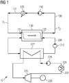
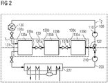
- FIGS 1 and 2 schematically show a thermal energy storage plant 10 comprising a charging circuit 100 and a discharging circuit 200, where, respectively, a first working fluid and a second working fluid are circulated.
- the first and the second working fluid may be in particular the same, for example being both constituted by hot air.
- the first and second working fluids may be different gaseous or liquid or steam media.
- the charging circuit 100 includes, in a closed loop:
- the first fluid transporting machine 110 is immediately downstream the cold end 132 of the heat accumulator 130. Alternatively (not shown), the first fluid transporting machine 110 is immediately upstream the hot end 131 of the heat accumulator 130.
- the first fluid transporting machine 110 may be constituted by a fan or blower.
- the heating device 120 may be a resistant or inductive heater or a heat pump fed by the electrical power generated by a renewable energy source, for example the wind speed generating power by means of a wind turbine or solar radiation generating power by means of photovoltaic cells, or from the electricity grid.
- the heating device 120 permits the first hot temperature T1 and the second low temperature T2 to be established between the hot end 131 and cold end 132 of the heat accumulator 130.
- values of T2 may be close to ambient temperature or 300 °C.
- the value of hot temperature T1 depends on the operating temperature of a thermal cycle 220 comprised in the discharging circuit 200 for transforming the thermal energy from the second working fluid into mechanical power, as detailed in the following.
- the low temperature T2 is typically kept higher than ambient temperature in order to reduce the heat load required in the heating device 120 for raising the first working fluid temperature up to the high temperature T1.
- the heat accumulator 130 is oriented in such a way that the first working fluid is circulated from the hot end 131 to the cold end 132 along a horizontal direction.
- the temperature front which forms between the hot end 131 and the cold 132 of the heat accumulator 130 travels horizontally, from the hot end 131 to the cold end 132.
- the temperature front so oriented typically tends to tilt, in particular during idle periods, for the effect of natural convection.
- the discharging circuit 200 includes, in closed loop:
- the thermal cycle 220 is a cycle including a thermal machine 225 and wherein the heat exchanger 227 is a steam generator for transferring thermal energy from the second working fluid to a mass of water in order to generate steam to be fed to the thermal machine 225.
- the thermal machine 225 may be a steam turbine having an output shaft connected to an electrical generator 226 to produce electricity to be fed in a electricity grid.
- the thermal cycle 220 may include, instead of the steam generator 227, a boiler or an evaporator or other type of heat exchanger for transferring heat from the second working fluid to the thermal cycle 220.
- the thermal cycle 220 further includes a condenser 228, connected to the outlet of the steam turbine 225 and a pump 229, between the condenser 228 and steam generator 227.
- Other types of thermal cycles may be used instead of the described thermal cycle 220, provided that, in general, they are able to transform the thermal energy from the discharging circuit 200 into mechanical power for powering the electrical generator 226.
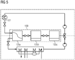
- the heat accumulator 130 comprises a plurality of heat storage units (three heat storage units 135a, 135b, 135c in the non-limiting embodiment of the attached figures) connected in series between the hot end 131 and the cold end 132.
- each heat storage unit 135a, 135b, 135c comprises respectively a housing 150a, 150b, 150c extending from an inlet 138a, 138b, 138c to an outlet 139a, 139b, 139c.
- Each housing 150a, 150b, 150c contains a plurality of heat storing elements 160 having high thermal capacity, for example solid or bulk materials like stones, bricks, ceramics and other solid materials, which have the ability to be heated up and to keep their temperature over a long period of time in order to store the thermal energy which has been transferred to them.
- Each heat storage unit 135a, 135b, 135c is configured for working with the same working fluid to be used for the charging circuit 100 and for the discharging circuit.
- the working fluid for example air
- the discharging circuit 200 the same working fluid flows from the outlet 139a, 139b, 139c to the inlet 138a, 138b, 138c, receiving heat from the storing elements 160.
- heat storage unit may be used, in particular being configured for the use with two working fluids, one for the charging circuit 100, the other for the discharging circuit 200. This may be achieved, for example, providing the each heat storage unit 135a, 135b, 135c with a first inlet and a first outlet for the first working fluid and with a second inlet and a second outlet for the second working fluid.
- the heat accumulator 130 further includes one or more valves (two valves 137a, 137b, in the non-limiting embodiment of the attached figures) interposed between respective couples of consecutive heat storage units 135a, 135b, 135c.
- a first valve 137a is placed on a pipe connecting the outlet 139a, 139b, 139c of the first (i.e.
- heat storage unit 135a with the inlet 138a, 138b, 138c of the intermediate heat storage unit 135b while a second valve 137b is placed on a pipe connecting the outlet 139a, 139b, 139c of the intermediate heat storage unit 135b with the inlet 138a, 138b, 138c of the last (i.e. closest to the cold end 132) heat storage unit 135c.
- a method for operating the thermal energy storage plant 10, during charging of the heat accumulator 130 comprises the steps of:
- the temperature profile is constant from the respective inlet 138a, 138b to the respective outlet 139a, 139b. This will prevent the occurrence of natural convection in the first and intermediate heat storage units 135a, 135b.
- This condition can be maintained easily by closing the valves 137a, 137b between the heat storage units 135a, 135b, 135c, in particular the second valve 137b between the intermediate and last heat storage units 135b, 135c. In such a way, natural convection which may occur in the last heat storage unit135c will not influence the other heat storage units 135a, 135b.
- the same result can be obtained, according to other embodiments of the present invention, using a different number of heat storage units, for example two or more than three heat storage units.
- the same result cannot be obtained with only one heat storage unit, because in this case it will not be possible to isolate the portion of the heat accumulator 130 having a constant temperature profile from the portion of the heat accumulator 130 containing the temperature front.
- only the second valve 137b is closed for isolating only the last heat storage unit 135c, i.e. the heat storage unit which includes the temperature front after the charging has been completed. With reference to the embodiment of the attached figures, this leaves the first and intermediate heat storage units 135a, 135b, which have a constant temperature profile, in communication with one another, but isolated from the last heat storage unit 135c.
- intermediate charging states may be possible, e.g. when wind conditions do not allow for full charging of the storage. In that case, it is not the last heat storage unit 135c, which contains the temperature gradient but, for example, the intermediate heat storage unit 135b.
- a method for operating the thermal energy storage plant 10, during discharging of the heat accumulator 130 comprises the steps of:
- the heat received from the storing elements 160 is then transferred from the second working fluid to the thermal cycle 220.
Landscapes
- Engineering & Computer Science (AREA)
- Mechanical Engineering (AREA)
- General Engineering & Computer Science (AREA)
- Physics & Mathematics (AREA)
- Thermal Sciences (AREA)
- Chemical & Material Sciences (AREA)
- Combustion & Propulsion (AREA)
- Dispersion Chemistry (AREA)
- Engine Equipment That Uses Special Cycles (AREA)
Claims (4)
- Procédé d'exploitation d'une centrale d'accumulation thermique (10) comprenant un circuit de charge (100) où un premier fluide de travail est mis en circulation, le circuit de charge (100) incluant :- une première machine de transport de fluide (110) pour générer un écoulement du premier fluide de travail dans le circuit de charge (100),- un dispositif de chauffage (120) pour transférer de la chaleur au premier fluide de travail,- un accumulateur de chaleur (130) pour accumuler l'énergie thermique du premier fluide de travail, l'accumulateur de chaleur (130) incluant une extrémité chaude (131) pour recevoir le premier fluide de travail à une première température (T1) et une extrémité froide (132) pour laisser le premier fluide de travail sortir de l'accumulateur de chaleur (130) à une seconde température (T2) inférieure à la première température (T1),l'accumulateur de chaleur (130) comprenant une pluralité d'unités d'accumulation de chaleur (135a, 135b, 135c) connectées en série entre l'extrémité chaude (131) et l'extrémité froide (132),
dans lequel l'accumulateur de chaleur (130) est orienté d'une manière telle que le premier fluide de travail est mis en circulation de l'extrémité chaude (131) à l'extrémité froide (132) le long d'une direction horizontale,
et au moins une vanne (137a, 137b) interposée entre deux unités d'accumulation de chaleur (135a, 135b, 135c) de ladite pluralité d'unités d'accumulation de chaleur (135a, 135b, 135c),
dans lequel la centrale d'accumulation thermique (10) comprend en outre un circuit de décharge (200) où un second fluide de travail est mis en circulation, le circuit de décharge (200) incluant :- l'accumulateur de chaleur (130),- une seconde machine de transport de fluide (210) pour générer un écoulement du second fluide de travail dans le circuit de décharge (200), l'écoulement étant orienté de l'extrémité froide (132) à l'extrémité chaude (131) de l'accumulateur de chaleur (130),- un échangeur de chaleur (227) inclus dans un cycle thermique (220) pour transférer l'énergie thermique du second fluide de travail au fluide de travail du cycle thermique (220),le procédé comprenant les étapes consistant à :- chauffer le premier fluide de travail dans le dispositif de chauffage (120),- générer un écoulement du premier fluide de travail dans le circuit de charge (100) avec la première machine de transport de fluide (110), pour charger les unités d'accumulation de chaleur (135a, 135b, 135c) en série de l'extrémité chaude (131) à l'extrémité froide (132), de sorte que le front de température se déplace de la première unité d'accumulation de chaleur (135a) à la dernière unité d'accumulation de chaleur (135c),caractérisé en ce que le procédé comprend en outre les étapes consistant à :- arrêter le chauffage et l'écoulement du premier fluide de travail après que la dernière unité d'accumulation de chaleur (135c) a été chargée, à savoir lorsque le front de température atteint la sortie de la dernière unité d'accumulation de chaleur (135c) et la seconde température (T2) à l'extrémité froide (132) augmente,- isoler l'unité d'accumulation de chaleur chargée (135c) des autres unités d'accumulation de chaleur (135a, 135b) au moyen d'au moins une vanne (137a, 137b). - Procédé selon la revendication 1, dans lequel le dispositif de chauffage (120) est alimenté par une source d'énergie renouvelable.
- Procédé selon la revendication 1, dans lequel la totalité des unités d'accumulation de chaleur (135a, 135b, 135c) sont isolées les unes des autres, au moyen de l'au moins une vanne (137a, 137b) disposée entre les unités d'accumulation de chaleur (135a, 135b, 135c).
- Procédé d'exploitation de la centrale d'accumulation thermique (10) selon l'une quelconque des revendications précédentes, le procédé comprenant les étapes consistant à :- ouvrir les vannes (137a, 137b)- générer un écoulement du second fluide de travail dans le circuit de décharge (200), de l'extrémité froide (132) à l'extrémité chaude (131), pour transférer de la chaleur des unités d'accumulation de chaleur (135a, 135b, 135c) au second fluide de travail,- arrêter le chauffage et l'écoulement du second fluide de travail après qu'une entrée (138a) d'une unité d'accumulation de chaleur (135a) qui est la plus proche de l'extrémité chaude (131) a atteint une température inférieure à la première température (T1).
Applications Claiming Priority (1)
| Application Number | Priority Date | Filing Date | Title |
|---|---|---|---|
| PCT/EP2015/055918 WO2016150461A1 (fr) | 2015-03-20 | 2015-03-20 | Centrale d'accumulation thermique |
Publications (2)
| Publication Number | Publication Date |
|---|---|
| EP3245466A1 EP3245466A1 (fr) | 2017-11-22 |
| EP3245466B1 true EP3245466B1 (fr) | 2019-09-25 |
Family
ID=53724205
Family Applications (1)
| Application Number | Title | Priority Date | Filing Date |
|---|---|---|---|
| EP15741756.9A Active EP3245466B1 (fr) | 2015-03-20 | 2015-03-20 | Procédé d'exploitation d'une centrale d'accumulation thermique |
Country Status (6)
| Country | Link |
|---|---|
| US (1) | US10371013B2 (fr) |
| EP (1) | EP3245466B1 (fr) |
| CN (1) | CN107429578B (fr) |
| DK (1) | DK3245466T3 (fr) |
| ES (1) | ES2763902T3 (fr) |
| WO (1) | WO2016150461A1 (fr) |
Cited By (1)
| Publication number | Priority date | Publication date | Assignee | Title |
|---|---|---|---|---|
| DE202023000696U1 (de) | 2023-03-29 | 2023-05-03 | Thomas Seidenschnur | Multi-Modul Hochtemperatur-Wärmespeicher mit serieller Be- und Entladung |
Families Citing this family (20)
| Publication number | Priority date | Publication date | Assignee | Title |
|---|---|---|---|---|
| CH710944A1 (de) * | 2015-04-08 | 2016-10-14 | Freepan Company Holdings Ltd | Prozesssystem für die Rekuperation von Wärme und Verfahren zu dessen Betrieb. |
| ES2733034T3 (es) * | 2015-09-30 | 2019-11-27 | Siemens Gamesa Renewable Energy As | Sistema de intercambio de calor con cámara de intercambio de calor principal y cámara de intercambio de calor secundaria y procedimiento para intercambiar calor usando el sistema de intercambio de calor |
| FR3051549B1 (fr) * | 2016-05-18 | 2018-06-22 | IFP Energies Nouvelles | Dispositif et procede de stockage et de restitution de la chaleur comprenant au moins deux volumes de stockage de la chaleur concentriques |
| CH712513A1 (de) | 2016-05-18 | 2017-11-30 | Synhelion Sa C/O Avv Luca Tenchio | Prozesssystem für die Rekuperation von Wärme und Verfahren zu dessen Betrieb. |
| EP3680459A1 (fr) * | 2019-01-11 | 2020-07-15 | Siemens Gamesa Renewable Energy GmbH & Co. KG | Dispositif de stockage d'énergie thermique |
| US12291982B2 (en) * | 2020-11-30 | 2025-05-06 | Rondo Energy, Inc. | Thermal energy storage systems for use in material processing |
| EP3757500A1 (fr) * | 2019-06-28 | 2020-12-30 | Siemens Gamesa Renewable Energy GmbH & Co. KG | Dispositif de stockage d'énergie thermique |
| IT201900025261A1 (it) | 2019-12-23 | 2021-06-23 | Energy Dome S P A | Impianto e processo per accumulare e scaricare energia termica |
| MA71196B1 (fr) | 2020-11-30 | 2025-04-30 | Rondo Energy, Inc. | Système et applications de stockage d'énergie |
| US12578152B2 (en) * | 2021-09-22 | 2026-03-17 | Wellhead Power Solutions, Llc | Thermal energy storage system |
| ES1288369Y (es) * | 2022-02-09 | 2022-06-15 | Rpow Consulting S L | Instalacion de almacenamiento energetico mejorada |
| CN116164571A (zh) * | 2022-12-14 | 2023-05-26 | 苏州市兴鲁空分设备科技发展有限公司 | 储能装置及其能量储存利用方法 |
| JP7783843B2 (ja) * | 2023-02-13 | 2025-12-10 | 株式会社東芝 | 蓄熱システム |
| DE102023209285A1 (de) * | 2023-09-22 | 2025-03-27 | Siemens Energy Global GmbH & Co. KG | Verfahren zur thermischen Energiespeicherung und thermischer Energiespeicher |
| WO2025226989A2 (fr) | 2024-04-24 | 2025-10-30 | Rondo Energy, Inc. | Système de stockage d'énergie thermique pour génération d'énergie de cycle simple et combinée |
| WO2025245498A1 (fr) | 2024-05-24 | 2025-11-27 | Rondo Energy, Inc. | Système de stockage d'énergie thermique à commande de dispositif de chauffage à haut rendement |
| US12566034B1 (en) | 2024-07-02 | 2026-03-03 | Rondo Energy, Inc. | Thermal energy storage system coupled to a heat exchanger with thermal protection |
| US12607170B2 (en) | 2024-07-12 | 2026-04-21 | Rondo Energy, Inc. | Thermal energy storage system for use with a low temperature heat source and a thermal power cycle system |
| DE102024206621A1 (de) * | 2024-07-15 | 2026-01-15 | Siemens Energy Global GmbH & Co. KG | Verfahren zur thermischen Energiespeicherung und thermischer Energiespeicher |
| CN120313394A (zh) * | 2025-05-09 | 2025-07-15 | 江苏君汇科技有限公司 | 一种流动介质填充床储能系统 |
Citations (4)
| Publication number | Priority date | Publication date | Assignee | Title |
|---|---|---|---|---|
| WO2012127178A1 (fr) * | 2011-03-23 | 2012-09-27 | Isentropic Ltd | Appareil de stockage de chaleur perfectionné |
| WO2013070396A1 (fr) * | 2011-11-10 | 2013-05-16 | Abengoa Solar Inc. | Procédés et appareil pour l'optimisation du contrôle de stockage de l'énergie thermique |
| WO2013160650A2 (fr) * | 2012-04-23 | 2013-10-31 | Isentropic Ltd | Accumulateur d'énergie thermique amélioré |
| US20150040564A1 (en) * | 2012-09-10 | 2015-02-12 | Hse Hitit Solar Enerji Anonim Sirketi | Solar energy system |
Family Cites Families (11)
| Publication number | Priority date | Publication date | Assignee | Title |
|---|---|---|---|---|
| US4215553A (en) * | 1978-06-26 | 1980-08-05 | Sanders Associates, Inc. | Energy conversion system |
| US4283914A (en) * | 1979-04-17 | 1981-08-18 | Allen Leonard W | Solar energy system |
| DE4121460A1 (de) * | 1991-06-28 | 1993-01-14 | Deutsche Forsch Luft Raumfahrt | Waermespeichersystem mit kombiniertem waermespeicher |
| MX2009009627A (es) * | 2007-03-08 | 2009-11-26 | Univ City | Planta de energia solar y metodo y/o sistema de almacenamiento de energia en una planta concentradora de energia solar. |
| US7971437B2 (en) * | 2008-07-14 | 2011-07-05 | Bell Independent Power Corporation | Thermal energy storage systems and methods |
| ATE503915T1 (de) * | 2008-07-16 | 2011-04-15 | Abb Research Ltd | Thermoelektrisches energiespeichersystem und verfahren zur speicherung von thermoelektrischer energie |
| US9671171B2 (en) * | 2009-09-17 | 2017-06-06 | Bluelagoon Technologies Ltd. | Systems and methods of thermal transfer and/or storage |
| WO2011104556A2 (fr) * | 2010-02-24 | 2011-09-01 | Isentropic Limited | Système amélioré pour le stockage de chaleur |
| JP2011231636A (ja) | 2010-04-26 | 2011-11-17 | Mitsubishi Heavy Ind Ltd | 排熱回収発電装置およびこれを備えた船舶 |
| EP2698505A1 (fr) * | 2012-08-14 | 2014-02-19 | Siemens Aktiengesellschaft | Procédé de chargement et de déchargement d'un accumulateur thermique et installation pour le stockage et le dépôt d'énergie thermique appropriée à ce procédé |
| DE102012215572A1 (de) | 2012-09-03 | 2014-03-06 | Siemens Aktiengesellschaft | Vorrichtung zur schnellen Wirkleistungsänderung von Kraftwerksanlagen |
-
2015
- 2015-03-20 DK DK15741756.9T patent/DK3245466T3/da active
- 2015-03-20 WO PCT/EP2015/055918 patent/WO2016150461A1/fr not_active Ceased
- 2015-03-20 CN CN201580078037.9A patent/CN107429578B/zh not_active Expired - Fee Related
- 2015-03-20 US US15/556,417 patent/US10371013B2/en active Active
- 2015-03-20 EP EP15741756.9A patent/EP3245466B1/fr active Active
- 2015-03-20 ES ES15741756T patent/ES2763902T3/es active Active
Patent Citations (4)
| Publication number | Priority date | Publication date | Assignee | Title |
|---|---|---|---|---|
| WO2012127178A1 (fr) * | 2011-03-23 | 2012-09-27 | Isentropic Ltd | Appareil de stockage de chaleur perfectionné |
| WO2013070396A1 (fr) * | 2011-11-10 | 2013-05-16 | Abengoa Solar Inc. | Procédés et appareil pour l'optimisation du contrôle de stockage de l'énergie thermique |
| WO2013160650A2 (fr) * | 2012-04-23 | 2013-10-31 | Isentropic Ltd | Accumulateur d'énergie thermique amélioré |
| US20150040564A1 (en) * | 2012-09-10 | 2015-02-12 | Hse Hitit Solar Enerji Anonim Sirketi | Solar energy system |
Cited By (1)
| Publication number | Priority date | Publication date | Assignee | Title |
|---|---|---|---|---|
| DE202023000696U1 (de) | 2023-03-29 | 2023-05-03 | Thomas Seidenschnur | Multi-Modul Hochtemperatur-Wärmespeicher mit serieller Be- und Entladung |
Also Published As
| Publication number | Publication date |
|---|---|
| CN107429578B (zh) | 2020-06-23 |
| ES2763902T3 (es) | 2020-06-01 |
| EP3245466A1 (fr) | 2017-11-22 |
| US20180106165A1 (en) | 2018-04-19 |
| WO2016150461A1 (fr) | 2016-09-29 |
| DK3245466T3 (da) | 2020-01-02 |
| US10371013B2 (en) | 2019-08-06 |
| CN107429578A (zh) | 2017-12-01 |
Similar Documents
| Publication | Publication Date | Title |
|---|---|---|
| EP3245466B1 (fr) | Procédé d'exploitation d'une centrale d'accumulation thermique | |
| CN104813131B (zh) | 热能储存系统及使用该热能储存系统的方法 | |
| CN108291532B (zh) | 太阳能发电装置及其控制方法 | |
| GB2542223A (en) | Thermal energy network | |
| EP3134685B1 (fr) | Système de chauffage et de refroidissement urbain à large bande | |
| EP3245389B1 (fr) | Centrale d'accumulation d'énergie thermique | |
| CN202004467U (zh) | 温差蓄能网电调峰系统 | |
| EP3256805B1 (fr) | Amélioration de l'efficacité des centrales électriques | |
| UA31378U (uk) | Система теплопостачання будівель | |
| US20220251976A1 (en) | Effective charging process of an energy conversion system | |
| US20220057148A1 (en) | Thermal energy storage device | |
| CN120303468A (zh) | 工业规模的发电厂、包括工业规模的发电厂和一个或多个应用设备的系统、对流烤箱以及热导热流体和冷导热流体供应方法 | |
| CN115997067A (zh) | 热能储存系统的操作 |
Legal Events
| Date | Code | Title | Description |
|---|---|---|---|
| STAA | Information on the status of an ep patent application or granted ep patent |
Free format text: STATUS: THE INTERNATIONAL PUBLICATION HAS BEEN MADE |
|
| PUAI | Public reference made under article 153(3) epc to a published international application that has entered the european phase |
Free format text: ORIGINAL CODE: 0009012 |
|
| STAA | Information on the status of an ep patent application or granted ep patent |
Free format text: STATUS: REQUEST FOR EXAMINATION WAS MADE |
|
| 17P | Request for examination filed |
Effective date: 20170809 |
|
| AK | Designated contracting states |
Kind code of ref document: A1 Designated state(s): AL AT BE BG CH CY CZ DE DK EE ES FI FR GB GR HR HU IE IS IT LI LT LU LV MC MK MT NL NO PL PT RO RS SE SI SK SM TR |
|
| AX | Request for extension of the european patent |
Extension state: BA ME |
|
| DAV | Request for validation of the european patent (deleted) | ||
| DAX | Request for extension of the european patent (deleted) | ||
| STAA | Information on the status of an ep patent application or granted ep patent |
Free format text: STATUS: EXAMINATION IS IN PROGRESS |
|
| 17Q | First examination report despatched |
Effective date: 20180905 |
|
| GRAP | Despatch of communication of intention to grant a patent |
Free format text: ORIGINAL CODE: EPIDOSNIGR1 |
|
| STAA | Information on the status of an ep patent application or granted ep patent |
Free format text: STATUS: GRANT OF PATENT IS INTENDED |
|
| GRAJ | Information related to disapproval of communication of intention to grant by the applicant or resumption of examination proceedings by the epo deleted |
Free format text: ORIGINAL CODE: EPIDOSDIGR1 |
|
| STAA | Information on the status of an ep patent application or granted ep patent |
Free format text: STATUS: EXAMINATION IS IN PROGRESS |
|
| RIC1 | Information provided on ipc code assigned before grant |
Ipc: F01K 3/12 20060101ALN20190225BHEP Ipc: F01K 3/18 20060101ALN20190225BHEP Ipc: F28F 27/00 20060101ALI20190225BHEP Ipc: F28D 17/04 20060101ALN20190225BHEP Ipc: F28D 17/00 20060101ALI20190225BHEP Ipc: F01K 5/00 20060101ALI20190225BHEP Ipc: F28D 17/02 20060101AFI20190225BHEP Ipc: F28D 20/00 20060101ALI20190225BHEP |
|
| INTG | Intention to grant announced |
Effective date: 20190312 |
|
| GRAP | Despatch of communication of intention to grant a patent |
Free format text: ORIGINAL CODE: EPIDOSNIGR1 |
|
| STAA | Information on the status of an ep patent application or granted ep patent |
Free format text: STATUS: GRANT OF PATENT IS INTENDED |
|
| INTC | Intention to grant announced (deleted) | ||
| RIC1 | Information provided on ipc code assigned before grant |
Ipc: F28D 17/04 20060101ALN20190402BHEP Ipc: F28D 17/00 20060101ALI20190402BHEP Ipc: F28D 17/02 20060101AFI20190402BHEP Ipc: F01K 3/12 20060101ALN20190402BHEP Ipc: F01K 5/00 20060101ALI20190402BHEP Ipc: F28F 27/00 20060101ALI20190402BHEP Ipc: F01K 3/18 20060101ALN20190402BHEP Ipc: F28D 20/00 20060101ALI20190402BHEP |
|
| INTG | Intention to grant announced |
Effective date: 20190416 |
|
| RAP1 | Party data changed (applicant data changed or rights of an application transferred) |
Owner name: SIEMENS GAMESA RENEWABLE ENERGY A/S |
|
| GRAS | Grant fee paid |
Free format text: ORIGINAL CODE: EPIDOSNIGR3 |
|
| GRAA | (expected) grant |
Free format text: ORIGINAL CODE: 0009210 |
|
| STAA | Information on the status of an ep patent application or granted ep patent |
Free format text: STATUS: THE PATENT HAS BEEN GRANTED |
|
| AK | Designated contracting states |
Kind code of ref document: B1 Designated state(s): AL AT BE BG CH CY CZ DE DK EE ES FI FR GB GR HR HU IE IS IT LI LT LU LV MC MK MT NL NO PL PT RO RS SE SI SK SM TR |
|
| REG | Reference to a national code |
Ref country code: GB Ref legal event code: FG4D |
|
| REG | Reference to a national code |
Ref country code: CH Ref legal event code: EP |
|
| REG | Reference to a national code |
Ref country code: DE Ref legal event code: R096 Ref document number: 602015038661 Country of ref document: DE |
|
| REG | Reference to a national code |
Ref country code: AT Ref legal event code: REF Ref document number: 1184212 Country of ref document: AT Kind code of ref document: T Effective date: 20191015 |
|
| REG | Reference to a national code |
Ref country code: IE Ref legal event code: FG4D |
|
| REG | Reference to a national code |
Ref country code: DK Ref legal event code: T3 Effective date: 20191217 |
|
| REG | Reference to a national code |
Ref country code: NL Ref legal event code: MP Effective date: 20190925 |
|
| PG25 | Lapsed in a contracting state [announced via postgrant information from national office to epo] |
Ref country code: LT Free format text: LAPSE BECAUSE OF FAILURE TO SUBMIT A TRANSLATION OF THE DESCRIPTION OR TO PAY THE FEE WITHIN THE PRESCRIBED TIME-LIMIT Effective date: 20190925 Ref country code: FI Free format text: LAPSE BECAUSE OF FAILURE TO SUBMIT A TRANSLATION OF THE DESCRIPTION OR TO PAY THE FEE WITHIN THE PRESCRIBED TIME-LIMIT Effective date: 20190925 Ref country code: BG Free format text: LAPSE BECAUSE OF FAILURE TO SUBMIT A TRANSLATION OF THE DESCRIPTION OR TO PAY THE FEE WITHIN THE PRESCRIBED TIME-LIMIT Effective date: 20191225 Ref country code: SE Free format text: LAPSE BECAUSE OF FAILURE TO SUBMIT A TRANSLATION OF THE DESCRIPTION OR TO PAY THE FEE WITHIN THE PRESCRIBED TIME-LIMIT Effective date: 20190925 Ref country code: HR Free format text: LAPSE BECAUSE OF FAILURE TO SUBMIT A TRANSLATION OF THE DESCRIPTION OR TO PAY THE FEE WITHIN THE PRESCRIBED TIME-LIMIT Effective date: 20190925 Ref country code: NO Free format text: LAPSE BECAUSE OF FAILURE TO SUBMIT A TRANSLATION OF THE DESCRIPTION OR TO PAY THE FEE WITHIN THE PRESCRIBED TIME-LIMIT Effective date: 20191225 |
|
| REG | Reference to a national code |
Ref country code: LT Ref legal event code: MG4D |
|
| PG25 | Lapsed in a contracting state [announced via postgrant information from national office to epo] |
Ref country code: RS Free format text: LAPSE BECAUSE OF FAILURE TO SUBMIT A TRANSLATION OF THE DESCRIPTION OR TO PAY THE FEE WITHIN THE PRESCRIBED TIME-LIMIT Effective date: 20190925 Ref country code: GR Free format text: LAPSE BECAUSE OF FAILURE TO SUBMIT A TRANSLATION OF THE DESCRIPTION OR TO PAY THE FEE WITHIN THE PRESCRIBED TIME-LIMIT Effective date: 20191226 Ref country code: LV Free format text: LAPSE BECAUSE OF FAILURE TO SUBMIT A TRANSLATION OF THE DESCRIPTION OR TO PAY THE FEE WITHIN THE PRESCRIBED TIME-LIMIT Effective date: 20190925 |
|
| REG | Reference to a national code |
Ref country code: AT Ref legal event code: MK05 Ref document number: 1184212 Country of ref document: AT Kind code of ref document: T Effective date: 20190925 |
|
| PG25 | Lapsed in a contracting state [announced via postgrant information from national office to epo] |
Ref country code: PL Free format text: LAPSE BECAUSE OF FAILURE TO SUBMIT A TRANSLATION OF THE DESCRIPTION OR TO PAY THE FEE WITHIN THE PRESCRIBED TIME-LIMIT Effective date: 20190925 Ref country code: AT Free format text: LAPSE BECAUSE OF FAILURE TO SUBMIT A TRANSLATION OF THE DESCRIPTION OR TO PAY THE FEE WITHIN THE PRESCRIBED TIME-LIMIT Effective date: 20190925 Ref country code: EE Free format text: LAPSE BECAUSE OF FAILURE TO SUBMIT A TRANSLATION OF THE DESCRIPTION OR TO PAY THE FEE WITHIN THE PRESCRIBED TIME-LIMIT Effective date: 20190925 Ref country code: NL Free format text: LAPSE BECAUSE OF FAILURE TO SUBMIT A TRANSLATION OF THE DESCRIPTION OR TO PAY THE FEE WITHIN THE PRESCRIBED TIME-LIMIT Effective date: 20190925 Ref country code: RO Free format text: LAPSE BECAUSE OF FAILURE TO SUBMIT A TRANSLATION OF THE DESCRIPTION OR TO PAY THE FEE WITHIN THE PRESCRIBED TIME-LIMIT Effective date: 20190925 Ref country code: IT Free format text: LAPSE BECAUSE OF FAILURE TO SUBMIT A TRANSLATION OF THE DESCRIPTION OR TO PAY THE FEE WITHIN THE PRESCRIBED TIME-LIMIT Effective date: 20190925 Ref country code: PT Free format text: LAPSE BECAUSE OF FAILURE TO SUBMIT A TRANSLATION OF THE DESCRIPTION OR TO PAY THE FEE WITHIN THE PRESCRIBED TIME-LIMIT Effective date: 20200127 Ref country code: AL Free format text: LAPSE BECAUSE OF FAILURE TO SUBMIT A TRANSLATION OF THE DESCRIPTION OR TO PAY THE FEE WITHIN THE PRESCRIBED TIME-LIMIT Effective date: 20190925 |
|
| PG25 | Lapsed in a contracting state [announced via postgrant information from national office to epo] |
Ref country code: SM Free format text: LAPSE BECAUSE OF FAILURE TO SUBMIT A TRANSLATION OF THE DESCRIPTION OR TO PAY THE FEE WITHIN THE PRESCRIBED TIME-LIMIT Effective date: 20190925 Ref country code: SK Free format text: LAPSE BECAUSE OF FAILURE TO SUBMIT A TRANSLATION OF THE DESCRIPTION OR TO PAY THE FEE WITHIN THE PRESCRIBED TIME-LIMIT Effective date: 20190925 Ref country code: IS Free format text: LAPSE BECAUSE OF FAILURE TO SUBMIT A TRANSLATION OF THE DESCRIPTION OR TO PAY THE FEE WITHIN THE PRESCRIBED TIME-LIMIT Effective date: 20200224 Ref country code: CZ Free format text: LAPSE BECAUSE OF FAILURE TO SUBMIT A TRANSLATION OF THE DESCRIPTION OR TO PAY THE FEE WITHIN THE PRESCRIBED TIME-LIMIT Effective date: 20190925 |
|
| REG | Reference to a national code |
Ref country code: ES Ref legal event code: FG2A Ref document number: 2763902 Country of ref document: ES Kind code of ref document: T3 Effective date: 20200601 |
|
| REG | Reference to a national code |
Ref country code: DE Ref legal event code: R097 Ref document number: 602015038661 Country of ref document: DE |
|
| PG2D | Information on lapse in contracting state deleted |
Ref country code: IS |
|
| PG25 | Lapsed in a contracting state [announced via postgrant information from national office to epo] |
Ref country code: IS Free format text: LAPSE BECAUSE OF FAILURE TO SUBMIT A TRANSLATION OF THE DESCRIPTION OR TO PAY THE FEE WITHIN THE PRESCRIBED TIME-LIMIT Effective date: 20200126 |
|
| PLBE | No opposition filed within time limit |
Free format text: ORIGINAL CODE: 0009261 |
|
| STAA | Information on the status of an ep patent application or granted ep patent |
Free format text: STATUS: NO OPPOSITION FILED WITHIN TIME LIMIT |
|
| 26N | No opposition filed |
Effective date: 20200626 |
|
| PG25 | Lapsed in a contracting state [announced via postgrant information from national office to epo] |
Ref country code: MC Free format text: LAPSE BECAUSE OF FAILURE TO SUBMIT A TRANSLATION OF THE DESCRIPTION OR TO PAY THE FEE WITHIN THE PRESCRIBED TIME-LIMIT Effective date: 20190925 |
|
| REG | Reference to a national code |
Ref country code: CH Ref legal event code: PL |
|
| PG25 | Lapsed in a contracting state [announced via postgrant information from national office to epo] |
Ref country code: SI Free format text: LAPSE BECAUSE OF FAILURE TO SUBMIT A TRANSLATION OF THE DESCRIPTION OR TO PAY THE FEE WITHIN THE PRESCRIBED TIME-LIMIT Effective date: 20190925 |
|
| REG | Reference to a national code |
Ref country code: BE Ref legal event code: MM Effective date: 20200331 |
|
| PG25 | Lapsed in a contracting state [announced via postgrant information from national office to epo] |
Ref country code: LU Free format text: LAPSE BECAUSE OF NON-PAYMENT OF DUE FEES Effective date: 20200320 |
|
| PG25 | Lapsed in a contracting state [announced via postgrant information from national office to epo] |
Ref country code: FR Free format text: LAPSE BECAUSE OF NON-PAYMENT OF DUE FEES Effective date: 20200331 Ref country code: IE Free format text: LAPSE BECAUSE OF NON-PAYMENT OF DUE FEES Effective date: 20200320 Ref country code: LI Free format text: LAPSE BECAUSE OF NON-PAYMENT OF DUE FEES Effective date: 20200331 Ref country code: CH Free format text: LAPSE BECAUSE OF NON-PAYMENT OF DUE FEES Effective date: 20200331 |
|
| PG25 | Lapsed in a contracting state [announced via postgrant information from national office to epo] |
Ref country code: BE Free format text: LAPSE BECAUSE OF NON-PAYMENT OF DUE FEES Effective date: 20200331 |
|
| PGFP | Annual fee paid to national office [announced via postgrant information from national office to epo] |
Ref country code: GB Payment date: 20220324 Year of fee payment: 8 Ref country code: DK Payment date: 20220322 Year of fee payment: 8 |
|
| PG25 | Lapsed in a contracting state [announced via postgrant information from national office to epo] |
Ref country code: TR Free format text: LAPSE BECAUSE OF FAILURE TO SUBMIT A TRANSLATION OF THE DESCRIPTION OR TO PAY THE FEE WITHIN THE PRESCRIBED TIME-LIMIT Effective date: 20190925 Ref country code: MT Free format text: LAPSE BECAUSE OF FAILURE TO SUBMIT A TRANSLATION OF THE DESCRIPTION OR TO PAY THE FEE WITHIN THE PRESCRIBED TIME-LIMIT Effective date: 20190925 Ref country code: CY Free format text: LAPSE BECAUSE OF FAILURE TO SUBMIT A TRANSLATION OF THE DESCRIPTION OR TO PAY THE FEE WITHIN THE PRESCRIBED TIME-LIMIT Effective date: 20190925 |
|
| PG25 | Lapsed in a contracting state [announced via postgrant information from national office to epo] |
Ref country code: MK Free format text: LAPSE BECAUSE OF FAILURE TO SUBMIT A TRANSLATION OF THE DESCRIPTION OR TO PAY THE FEE WITHIN THE PRESCRIBED TIME-LIMIT Effective date: 20190925 |
|
| PGFP | Annual fee paid to national office [announced via postgrant information from national office to epo] |
Ref country code: ES Payment date: 20220420 Year of fee payment: 8 |
|
| REG | Reference to a national code |
Ref country code: DK Ref legal event code: EBP Effective date: 20230331 |
|
| GBPC | Gb: european patent ceased through non-payment of renewal fee |
Effective date: 20230320 |
|
| PG25 | Lapsed in a contracting state [announced via postgrant information from national office to epo] |
Ref country code: GB Free format text: LAPSE BECAUSE OF NON-PAYMENT OF DUE FEES Effective date: 20230320 |
|
| PG25 | Lapsed in a contracting state [announced via postgrant information from national office to epo] |
Ref country code: GB Free format text: LAPSE BECAUSE OF NON-PAYMENT OF DUE FEES Effective date: 20230320 |
|
| PG25 | Lapsed in a contracting state [announced via postgrant information from national office to epo] |
Ref country code: DK Free format text: LAPSE BECAUSE OF NON-PAYMENT OF DUE FEES Effective date: 20230331 |
|
| REG | Reference to a national code |
Ref country code: ES Ref legal event code: FD2A Effective date: 20240524 |
|
| PG25 | Lapsed in a contracting state [announced via postgrant information from national office to epo] |
Ref country code: ES Free format text: LAPSE BECAUSE OF NON-PAYMENT OF DUE FEES Effective date: 20230321 |
|
| PG25 | Lapsed in a contracting state [announced via postgrant information from national office to epo] |
Ref country code: ES Free format text: LAPSE BECAUSE OF NON-PAYMENT OF DUE FEES Effective date: 20230321 |
|
| PGFP | Annual fee paid to national office [announced via postgrant information from national office to epo] |
Ref country code: DE Payment date: 20250327 Year of fee payment: 11 |