EP3245596B1 - Système et procédé de mise à l'échelle élastique à l'aide d'une plateforme à base de conteneur - Google Patents
Système et procédé de mise à l'échelle élastique à l'aide d'une plateforme à base de conteneur Download PDFInfo
- Publication number
- EP3245596B1 EP3245596B1 EP16737894.2A EP16737894A EP3245596B1 EP 3245596 B1 EP3245596 B1 EP 3245596B1 EP 16737894 A EP16737894 A EP 16737894A EP 3245596 B1 EP3245596 B1 EP 3245596B1
- Authority
- EP
- European Patent Office
- Prior art keywords
- service
- container
- platform
- virtual machines
- ptt
- Prior art date
- Legal status (The legal status is an assumption and is not a legal conclusion. Google has not performed a legal analysis and makes no representation as to the accuracy of the status listed.)
- Active
Links
Images







Classifications
-
- H—ELECTRICITY
- H04—ELECTRIC COMMUNICATION TECHNIQUE
- H04W—WIRELESS COMMUNICATION NETWORKS
- H04W4/00—Services specially adapted for wireless communication networks; Facilities therefor
- H04W4/06—Selective distribution of broadcast services, e.g. multimedia broadcast multicast service [MBMS]; Services to user groups; One-way selective calling services
- H04W4/10—Push-to-Talk [PTT] or Push-On-Call services
-
- G—PHYSICS
- G06—COMPUTING OR CALCULATING; COUNTING
- G06F—ELECTRIC DIGITAL DATA PROCESSING
- G06F9/00—Arrangements for program control, e.g. control units
- G06F9/06—Arrangements for program control, e.g. control units using stored programs, i.e. using an internal store of processing equipment to receive or retain programs
- G06F9/44—Arrangements for executing specific programs
- G06F9/455—Emulation; Interpretation; Software simulation, e.g. virtualisation or emulation of application or operating system execution engines
- G06F9/45533—Hypervisors; Virtual machine monitors
- G06F9/45558—Hypervisor-specific management and integration aspects
-
- H—ELECTRICITY
- H04—ELECTRIC COMMUNICATION TECHNIQUE
- H04L—TRANSMISSION OF DIGITAL INFORMATION, e.g. TELEGRAPHIC COMMUNICATION
- H04L41/00—Arrangements for maintenance, administration or management of data switching networks, e.g. of packet switching networks
- H04L41/08—Configuration management of networks or network elements
- H04L41/0893—Assignment of logical groups to network elements
-
- H—ELECTRICITY
- H04—ELECTRIC COMMUNICATION TECHNIQUE
- H04L—TRANSMISSION OF DIGITAL INFORMATION, e.g. TELEGRAPHIC COMMUNICATION
- H04L41/00—Arrangements for maintenance, administration or management of data switching networks, e.g. of packet switching networks
- H04L41/08—Configuration management of networks or network elements
- H04L41/0895—Configuration of virtualised networks or elements, e.g. virtualised network function or OpenFlow elements
-
- H—ELECTRICITY
- H04—ELECTRIC COMMUNICATION TECHNIQUE
- H04L—TRANSMISSION OF DIGITAL INFORMATION, e.g. TELEGRAPHIC COMMUNICATION
- H04L41/00—Arrangements for maintenance, administration or management of data switching networks, e.g. of packet switching networks
- H04L41/08—Configuration management of networks or network elements
- H04L41/0896—Bandwidth or capacity management, i.e. automatically increasing or decreasing capacities
- H04L41/0897—Bandwidth or capacity management, i.e. automatically increasing or decreasing capacities by horizontal or vertical scaling of resources, or by migrating entities, e.g. virtual resources or entities
-
- H—ELECTRICITY
- H04—ELECTRIC COMMUNICATION TECHNIQUE
- H04L—TRANSMISSION OF DIGITAL INFORMATION, e.g. TELEGRAPHIC COMMUNICATION
- H04L41/00—Arrangements for maintenance, administration or management of data switching networks, e.g. of packet switching networks
- H04L41/12—Discovery or management of network topologies
-
- H—ELECTRICITY
- H04—ELECTRIC COMMUNICATION TECHNIQUE
- H04L—TRANSMISSION OF DIGITAL INFORMATION, e.g. TELEGRAPHIC COMMUNICATION
- H04L41/00—Arrangements for maintenance, administration or management of data switching networks, e.g. of packet switching networks
- H04L41/50—Network service management, e.g. ensuring proper service fulfilment according to agreements
- H04L41/5041—Network service management, e.g. ensuring proper service fulfilment according to agreements characterised by the time relationship between creation and deployment of a service
-
- H—ELECTRICITY
- H04—ELECTRIC COMMUNICATION TECHNIQUE
- H04L—TRANSMISSION OF DIGITAL INFORMATION, e.g. TELEGRAPHIC COMMUNICATION
- H04L65/00—Network arrangements, protocols or services for supporting real-time applications in data packet communication
- H04L65/10—Architectures or entities
- H04L65/1045—Proxies, e.g. for session initiation protocol [SIP]
-
- H—ELECTRICITY
- H04—ELECTRIC COMMUNICATION TECHNIQUE
- H04L—TRANSMISSION OF DIGITAL INFORMATION, e.g. TELEGRAPHIC COMMUNICATION
- H04L65/00—Network arrangements, protocols or services for supporting real-time applications in data packet communication
- H04L65/1066—Session management
- H04L65/1069—Session establishment or de-establishment
-
- H—ELECTRICITY
- H04—ELECTRIC COMMUNICATION TECHNIQUE
- H04L—TRANSMISSION OF DIGITAL INFORMATION, e.g. TELEGRAPHIC COMMUNICATION
- H04L65/00—Network arrangements, protocols or services for supporting real-time applications in data packet communication
- H04L65/1066—Session management
- H04L65/1073—Registration or de-registration
-
- H—ELECTRICITY
- H04—ELECTRIC COMMUNICATION TECHNIQUE
- H04L—TRANSMISSION OF DIGITAL INFORMATION, e.g. TELEGRAPHIC COMMUNICATION
- H04L65/00—Network arrangements, protocols or services for supporting real-time applications in data packet communication
- H04L65/40—Support for services or applications
- H04L65/4061—Push-to services, e.g. push-to-talk or push-to-video
-
- H—ELECTRICITY
- H04—ELECTRIC COMMUNICATION TECHNIQUE
- H04L—TRANSMISSION OF DIGITAL INFORMATION, e.g. TELEGRAPHIC COMMUNICATION
- H04L67/00—Network arrangements or protocols for supporting network services or applications
- H04L67/01—Protocols
- H04L67/10—Protocols in which an application is distributed across nodes in the network
-
- H—ELECTRICITY
- H04—ELECTRIC COMMUNICATION TECHNIQUE
- H04L—TRANSMISSION OF DIGITAL INFORMATION, e.g. TELEGRAPHIC COMMUNICATION
- H04L67/00—Network arrangements or protocols for supporting network services or applications
- H04L67/01—Protocols
- H04L67/10—Protocols in which an application is distributed across nodes in the network
- H04L67/1001—Protocols in which an application is distributed across nodes in the network for accessing one among a plurality of replicated servers
-
- H—ELECTRICITY
- H04—ELECTRIC COMMUNICATION TECHNIQUE
- H04L—TRANSMISSION OF DIGITAL INFORMATION, e.g. TELEGRAPHIC COMMUNICATION
- H04L67/00—Network arrangements or protocols for supporting network services or applications
- H04L67/01—Protocols
- H04L67/10—Protocols in which an application is distributed across nodes in the network
- H04L67/1001—Protocols in which an application is distributed across nodes in the network for accessing one among a plurality of replicated servers
- H04L67/1004—Server selection for load balancing
- H04L67/1008—Server selection for load balancing based on parameters of servers, e.g. available memory or workload
-
- H—ELECTRICITY
- H04—ELECTRIC COMMUNICATION TECHNIQUE
- H04L—TRANSMISSION OF DIGITAL INFORMATION, e.g. TELEGRAPHIC COMMUNICATION
- H04L67/00—Network arrangements or protocols for supporting network services or applications
- H04L67/01—Protocols
- H04L67/10—Protocols in which an application is distributed across nodes in the network
- H04L67/1001—Protocols in which an application is distributed across nodes in the network for accessing one among a plurality of replicated servers
- H04L67/1004—Server selection for load balancing
- H04L67/1017—Server selection for load balancing based on a round robin mechanism
-
- H—ELECTRICITY
- H04—ELECTRIC COMMUNICATION TECHNIQUE
- H04L—TRANSMISSION OF DIGITAL INFORMATION, e.g. TELEGRAPHIC COMMUNICATION
- H04L67/00—Network arrangements or protocols for supporting network services or applications
- H04L67/01—Protocols
- H04L67/10—Protocols in which an application is distributed across nodes in the network
- H04L67/1001—Protocols in which an application is distributed across nodes in the network for accessing one among a plurality of replicated servers
- H04L67/1031—Controlling of the operation of servers by a load balancer, e.g. adding or removing servers that serve requests
-
- H—ELECTRICITY
- H04—ELECTRIC COMMUNICATION TECHNIQUE
- H04L—TRANSMISSION OF DIGITAL INFORMATION, e.g. TELEGRAPHIC COMMUNICATION
- H04L67/00—Network arrangements or protocols for supporting network services or applications
- H04L67/50—Network services
- H04L67/51—Discovery or management thereof, e.g. service location protocol [SLP] or web services
-
- H—ELECTRICITY
- H04—ELECTRIC COMMUNICATION TECHNIQUE
- H04M—TELEPHONIC COMMUNICATION
- H04M7/00—Arrangements for interconnection between switching centres
- H04M7/006—Networks other than PSTN/ISDN providing telephone service, e.g. Voice over Internet Protocol (VoIP), including next generation networks with a packet-switched transport layer
-
- H—ELECTRICITY
- H04—ELECTRIC COMMUNICATION TECHNIQUE
- H04W—WIRELESS COMMUNICATION NETWORKS
- H04W4/00—Services specially adapted for wireless communication networks; Facilities therefor
- H04W4/06—Selective distribution of broadcast services, e.g. multimedia broadcast multicast service [MBMS]; Services to user groups; One-way selective calling services
- H04W4/08—User group management
-
- G—PHYSICS
- G06—COMPUTING OR CALCULATING; COUNTING
- G06F—ELECTRIC DIGITAL DATA PROCESSING
- G06F9/00—Arrangements for program control, e.g. control units
- G06F9/06—Arrangements for program control, e.g. control units using stored programs, i.e. using an internal store of processing equipment to receive or retain programs
- G06F9/44—Arrangements for executing specific programs
- G06F9/455—Emulation; Interpretation; Software simulation, e.g. virtualisation or emulation of application or operating system execution engines
- G06F9/45533—Hypervisors; Virtual machine monitors
- G06F9/45558—Hypervisor-specific management and integration aspects
- G06F2009/4557—Distribution of virtual machine instances; Migration and load balancing
Definitions
- the present invention relates generally to communications over a telecommunications network, and in particular embodiments, to techniques and mechanisms for a system and method for elastic scaling in push to talk (PTT).
- PTT push to talk
- US20140317261 describes an orchestrator system for managing interconnections between virtualized computing networks.
- Carrier grade telecommunication service deployments may have stringent service availability requirements and may further require geographical redundancy support.
- telecommunication systems are built using specialized hardware based components that support 1+1 redundancy or N+K redundancy.
- Each hardware component provides one or more services and the component is usually deployed as a fixed package of these services.
- desire to optimize hardware component cost during deployment drives the need to package multiple service components together and associate them with specific hardware components.
- telecommunication system component packages usually come with a variety of configuration options which makes testing and deployment a challenging endeavor. It is quite common for new service development and deployment cycles to last months or even years in the telecommunication service industry. Also, system capacity expansion requires careful planning due to hardware procurement lead times and complicated hardware installation and setup procedures. As a consequence, telecommunication systems are often overprovisioned to accommodate unexpected growth in service usage.
- Virtualization technology and the advent of cloud based Infrastructure-as-a-Service systems all the deployment several services in virtualized environments that support elastic scalability and facilitate rapid deployment through agile continuous integration procedures. This presents an opportunity for realizing substantial cost benefits by operating carrier grade telecommunication systems on modern cloud based infrastructure.
- applying methods of elastic scaling to carrier grade telecommunication services which are subject to stringent 99.999% service availability and service continuity requirements, result in various challenges.
- a method includes triggering, by a service orchestrator hosted on a processor, creation of one or more container instances for a first service cluster.
- the first service cluster provides a first service for a telecommunications services platform.
- the method further includes creating, by a container manager hosted on a processor, the one or more container instances and mapping, by the container manager, the one or more container instances of the first service cluster to one or more first virtual machines belonging to a first virtual machine server group in accordance with a platform profile of the first virtual machine server group and the first service provided by the first service cluster.
- the method further includes mapping, by a virtual machine manager hosted on a processor, the one or more first virtual machines to one or more first host virtual machines of a cloud network in accordance with the platform profile of the first virtual machine server group.
- the method further includes deploying the one or more first host virtual machines on one or more host processors.
- a method includes triggering, by a processor, creation of one or more container instances for a first service cluster.
- the first service cluster is one of a plurality of service clusters in a push-to-talk (PTT) platform, and each of the plurality of service clusters provides a different function for the PTT platform.
- the method further includes creating, by a processor, the one or more container instances and mapping, by a processor, the one or more container instances of the first service cluster to one or more first virtual machines belonging to a first virtual machine server group in accordance with a platform profile of the first virtual machine server group and a first PTT function provided by the first service cluster.
- the method further includes mapping, by a virtual machine manager hosted on a processor, the one or more virtual machines to one or more first host virtual machines of a cloud network in accordance with the platform profile of the first virtual machine server group.
- the cloud network is deployed independently from the PTT platform.
- the method further includes operating the one or more first host virtual machines on one or more host processors to provide the first PTT function for the PTT platform.
- a telecommunications services platform including: one or more processors and one or more computer readable storage mediums storing programming for execution by the one or more processors.
- the programming includes instructions to trigger, by a service orchestrator, creation of one or more container instances for a service cluster.
- the service cluster provides a function for the telecommunications services platform.
- the programming includes further instructions to create, by a container manager, the one or more container instances and map, by the container manager, the one or more container instances of the service cluster to one or more virtual machines belonging to a virtual machine server group in accordance with a platform profile of the virtual machine server group and the function provided by the service cluster.
- the programming includes further instructions to map, by a virtual machine manager hosted on a processor, the one or more virtual machines to one or more host virtual machines of a cloud network in accordance with the platform profile of the virtual machine server group and operate the one or more host virtual machines to provide the function for the telecommunications services platform.
- a container technology based platform e.g., a PTT platform or a PTT over cellular (PoC) platform
- An embodiment telecommunications service (e.g., a PTT service) may be realized on the container based platform.
- the telecommunications services platform uses a layered approach to service orchestration and automates both virtual machine and container manifestation to provide elastic scalability and fault tolerance. For example, management layers are decoupled to manage the physical infrastructure, virtual machines, containers, and services of the telecommunications services platform independently. The layered approach also allows the platform to be integrated into both containers based and hypervisor based service orchestration environments.
- Various embodiments also include mechanisms for balancing a service load within and across deployment sites and for using the platform for the realization of a PTT system.
- Various embodiment communications systems may thus achieve one or more of the following non-limiting features and/or advantages: virtualization and scalability; massively scalable cloud-compatible platform supporting multi-site deployments, dynamic load-balancing, and elastic scalability; flexible deployments across different cloud environments including a carrier's private cloud infrastructure; use of Software Defined Networking (SDN) and optimized or at least improved Network Function Virtualization (NFV); resilience and operational efficiency; self-healing service logic to automatically or semi-automatically recover from component failure; simple and efficient operational procedures to ensure carrier grade service for various subscribers; automated zero-downtime (or at least reduced downtime) rolling upgrade; and facilitating agile continuous integration processes for faster rollout of new features.
- SDN Software Defined Networking
- NFV Network Function Virtualization
- FIG. 1 illustrates a communications system 100, which provides an architecture for supporting a telecommunications service solution in accordance with some embodiments.
- Communications system 100 includes client devices 102, a communications network 104, and a telecommunications services platform 106.
- client device refers to any component (or collection of components) capable of establishing a connection with a communications network, such as a user equipment (UE), a mobile station (STA), a cellular phone, a tablet, a laptop, and other wirelessly enabled devices.
- Applications e.g., PTT clients
- Client devices 102 may communicate with a telecommunications services platform 106 over network 104 (e.g., the Internet, an IP network, or the like), which may be accessed by client devices 102 through a cellular network deployed by a carrier, a WiFi network, a radio access network (RAN), other wireless networks, a wired network, combinations thereof, or the like.
- Network 104 may include one or more components configured to provide wireless or wired network access, such as an enhanced base station (eNB), a macro-cell, a femtocell, a Wi-Fi access point (AP), combinations thereof, or the like.
- eNB enhanced base station
- AP Wi-Fi access point
- network 104 may operate in accordance with one or more wireless communication protocols, e.g., open mobile alliance (OMA), long term evolution (LTE), LTE advanced (LTE-A), High Speed Packet Access (HSPA), Wi-Fi 802.11a/b/g/n/ac, etc.
- OMA open mobile alliance
- LTE long term evolution
- LTE-A LTE advanced
- HSPA High Speed Packet Access
- Wi-Fi 802.11a/b/g/n/ac etc.
- network 104 may comprise various other devices, such as relays, low power nodes, etc.
- Network 104 may further include backhaul network components, such as various gateways, routers, controllers, schedulers, and the like.
- Subscribers to telecommunications service solution may be provisioned onto system 100 via interfaces to carriers (e.g., cellular carriers).
- carriers e.g., cellular carriers
- PTT customers e.g., enterprises
- the PTT solution may interface with the carrier, for example, by including connectivity to the carrier's core network, billing interfaces, provisioning interfaces, lawful intercept interfaces, customer care interfaces, and the like.
- Telecommunications services platform 106 may provide a plurality of functions to client devices 102 through the clients on client devices 102 as described in greater detail below.
- telecommunications services platform 106 uses container technology for virtualization of a system architecture, such as, the virtualization of provided PTT services.
- Example container technologies may include Docker, Rocket, LXD, and the like although the architecture is not limited to a specific container technology.
- Virtualization using container technology may allow telecommunications services platform 106 to adopt a micro-services model in which service clusters are considered the building blocks of the system architecture. For example, each service or function provided by telecommunications services platform 106 may be virtualized in a unique service cluster, and each service cluster may perform a different service or function in telecommunications services platform 106.
- each service cluster is realized by one or more of containers orchestrated to make up a respective service and operate together as a cluster to provide scalability and resilience.
- the containers of a service cluster may be a same type or different types.
- Each element (e.g., each container) of the cluster implements a mechanism to announce its availability and enables other components of the system to discover the element's interfaces.
- the telecommunications services platform may further implement self-healing service logic to automatically recover from component failure and include multi-site deployment capability for added resilience.
- the telecommunications service system architecture includes a collection of independent service clusters that communicate with each other through pre-defined interfaces to fulfill service work flows. Decomposition of the system architecture into a set of services allows each service (e.g., each function provided by the telecommunications services platform) to be independently deployed and managed. Thus, system resilience may be improved as failures are localized to individual services. Furthermore, rapid and agile deployment of services may also be achieved.
- telecommunications services platform 106 incorporates distributed databases, clustering technologies, data analytics tools, and high performance messaging middleware to provide a robust, scalable platform.
- Telecommunications services platform 106 may use fully virtualized components with layered approach to service orchestration, which allows telecommunications services platform 106 to be integrated into various cloud environments, such as a carrier's private cloud infrastructure, a dedicated cloud infrastructure for the telecommunications services platform (e.g., a dedicated PTT cloud infrastructure), combinations thereof, and the like.
- the cloud network and the telecommunications services platform 106 may be deployed independently to advantageously decouple design time considerations of the telecommunications services platform 106 from the actual deployment concerns of the cloud network.
- telecommunications services platform 106 may directly use the container level orchestration APIs to instantiate service containers as needed.
- container level orchestration APIs e.g., a hypervisor based infrastructure as a service (IaaS) cloud environments
- telecommunications services platform 106 may provide its own container management layer that is built on top of a virtual machine management layer. This approach allows telecommunications services platform 106 to provide a single container based execution environment to various service components irrespective of the physical deployment environment of telecommunications services platform 106.
- telecommunications services platform 106 decouples infrastructure deployment considerations from service deployment, and use of virtualization and container technology also allows the telecommunications services platform to break away from a traditional hardware-centric component model to system deployment.
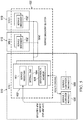
- An embodiment layered infrastructure management architecture of a telecommunications services platform 106 is illustrated in Figure 2 .
- telecommunications services platform 106's infrastructure management architecture 200 includes a service orchestration layer 202, a container management layer 204, a virtual infrastructure management layer 206, and a physical infrastructure layer 208.
- Each layer may include a controller, such as a virtual controller hosted on a processor for performing the various functions provided by the layer, a dedicated hardware controller, and the like.
- the controllers of each layer are setup as part of a bootstrap procedure for the platform. These controllers may be hosted on dedicated physical hardware or on one or more virtual compute node instances of physical infrastructure layer 208. In embodiments where the controllers are hosted on physical infrastructure layer 208, specific hardware resources may be reserved for the purpose of hosting the controllers.
- Service orchestration layer 202 is the highest layer of abstraction in infrastructure management architecture 200.
- Service orchestration layer 202 is a layer on top of which various service components that constitute the telecommunications services platform operate.
- a service orchestrator in service orchestration layer 202 uses service metrics to scale service clusters 210 (referred to collectively as the container cluster) for each service component (e.g., the various service components illustrated in Figure 3 , below).
- Scaling service clusters 210 may include transmitting scaling triggers to lower layers (e.g., container management layer 204). In some embodiments, the scaling of service clusters 210 may be in real time. These scaling triggers may be based on service metrics transmitted to service orchestration layer 202 from lower layers (e.g., container management layer 204).
- scaling triggers on based on service metrics collected from various service components running on respective service clusters in the platform.
- Embodiment service metrics for a PTT platform may include, for example, number of PTT pre-established sessions, PTT call setup rate, PTT call leg setup rate, number of concurrently active PTT calls, number of concurrently active PTT call legs, number of media codec instances in active use, combinations thereof, and the like.
- Service orchestration layer 202 may also create new container instances to replace failed container instances, for example, based on faults transmitted to service orchestration layer 202 from lower layers (e.g., container management layer 204).
- Container management layer 204 operates on top of a pool of virtual machines (e.g., compute nodes 212 in virtual infrastructure management layer 206) to manage the distribution of services clusters 210 across various compute nodes 212.
- container management layer 204 may manifest container instances for each service cluster 210 across compute nodes 212.
- container management layer 204 tracks platform metrics (e.g., computer processing unit (CPU) metrics, random access memory (RAM) metrics, combinations thereof, and the like) across various virtual machines (e.g., compute nodes 212) and uses these metrics to distribute the service container load (e.g., service clusters 210) across compute nodes 212.
- platform metrics e.g., computer processing unit (CPU) metrics, random access memory (RAM) metrics, combinations thereof, and the like
- each compute node 212 may be grouped into compute node clusters (also referred to as virtual machine server groups) based on a platform profile (e.g., CPU parameters, RAM parameters, storage parameters, network input/output (I/O) capacity, and the like) provided by a respective compute 212.
- Container management layer 204 manages compute node clusters with different platform profiles and maps service clusters 210 to compute nodes 212 providing computing resources in accordance with a service provided by and/or expected resource usage of a respective service cluster 210.
- Container management layer 204 may instantiate new compute nodes to scale the system when needed based on the platform metrics. For example, container management layer 204 may transmit scaling triggers to virtual infrastructure management layer 206 to instantiate new compute nodes or to remove compute nodes as desired. In some embodiments, container management layer 204 may also transmit desired compute node platform profiles with the scaling triggers to virtual infrastructure management layer 206.
- Container management layer 204 may ensure a desired redundancy in the system by distributing container instances belonging to a same service across multiple compute nodes. Container management layer 204 also triggers the creation of new compute nodes to replace failed instances. Container management layer 204 may also enforce container affinity policies to ensure that related container groups (e.g. a PTT server and a media server) are co-located on the same host. Platform design may determine which container groups (e.g., which service clusters) should be may be related.
- container groups e.g., which service clusters
- container groups e.g., a PTT call server and a PTT media server during a PTT call
- placing these container groups together on the same host will reduce latency (e.g., the latency of PTT call setup and floor control operations).
- Virtual infrastructure management layer 206 provides a bridge between orchestration layers (e.g., service orchestration layer 202 and container management layer 204) and the physical infrastructure (e.g., physical infrastructure layer 208) of the telecommunications services platform.
- Virtual infrastructure management layer 206 provides an abstract interface to the physical cloud infrastructure and allows telecommunications services platform 106 to be ported to different cloud environments.
- virtual infrastructure management layer 206 executes scaling triggers received from container management layer 204 and uses the underlying cloud infrastructure management APIs (e.g. OpenStack) to build up compute nodes (e.g., compute nodes 212) with a requested platform profile.
- the requested platform profile may include a combination of CPU parameters, RAM parameters, storage parameters, network I/O capacity, and the like as requested by container management layer 204.
- Physical infrastructure layer 208 can be provided as part of carrier's private cloud, a public cloud, or a combination thereof.
- Physical infrastructure layer 208 is a physical implementation of virtual infrastructure management layer 206.
- Various telecommunications services are encapsulated in containers, mapped to virtual machines, and hosted on physical hardware components (e.g., processors) in physical infrastructure layer 208.
- physical infrastructure layer 208 may use commercially available off-the-shelf (COTS) components, which may allow the implementation of telecommunications services platform 106 without specialized hardware.
- COTS off-the-shelf
- physical infrastructure layer 208 may be capable of spanning multiple datacenters at different sites to provide geographic redundancy for greater resiliency.
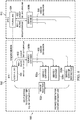
- FIG 3 illustrates a block diagram of service components 300 according to some embodiments where telecommunications services platform 106 is a PTT platform.
- Each service components 300 may be virtualized as a unique service cluster 210, distributed on virtual compute nodes 212, and implemented on a private/public cloud platform as described above with respect to Figure 2 .
- Service components 300 may be organized in one or more functional layers, such as a session layer 302, a service layer 304, and a data management layer 306.
- session layer 302 may include a session initiation protocol (SIP) proxy service 302a, a registrar service 302b, a notification service 302c, a session border controller (SBC) service 302d, a HTTP proxy service 302e, SMS dispatch service 302f, a quality of service (QoS) control interface adapter 302g, or a combination thereof.
- SIP proxy service 302a may route SIP traffic to corresponding services (e.g. call service, presence service, and the like); serve as a SIP load balancer; offload the client connection management from the backend services; enable all services to reach the client through a common connection; or a combination thereof.
- Registrar service 302b may maintain client connectivity information in a database (DB) that is shared with all (or at least a subset of) other services. The other services can use this data to route SIP messages to client via an appropriate SIP proxy instance. Registrar service 302b may also track the status of the proxy elements and identify/recover stale client sessions connections in the event of a proxy element failure. Notification service 302c allows all (or at least a subset of) services to send asynchronous notifications to clients via different mechanisms such as SIP, short message service (SMS), email, and the like. In some embodiments, clients may maintain an always-on
- SBC service 302d receives traffic entering into the PTT System from the internet protocol (IP) multimedia subsystem (IMS) core.
- SBC service 302d provides SIP application level gateway (ALG) and Media network address translation (NAT) functions.
- HTTP proxy service 302e may receive some or all HTTP traffic relating to provisioning, corporate data management, and client data management.
- SMS dispatch service 302f is used by notification service 302c to send SMS notifications related to the user's PTT service to the client. Some examples of the SMS notifications include service activation and deactivation messages, service maintenance alerts, and the like.
- QoS control interface adapter 302g provides a customizable interface to carrier's QoS control system (e.g. policy and changing rules function (PCRF) receive (Rx) interface) for implementing dynamic QoS control logic.
- PCRF policy and changing rules function
- service layer 304 may include PTT call service 304a, broadcast call service 304b, presence service 304c, PTT multimedia messaging service 304d, lawful intercept service 304e, or a combination thereof.
- PTT call Service 304a provides an entry point to all (or at least a subset of) call services to telecommunications services platform 106.
- PTT call service 304a manages POC pre-established sessions, for example, by handling one-on-one (1-1), pre-arranged group and adhoc group calls over on-demand and pre-established sessions.
- PTT call service 304a also implements predictive wakeup technology (e.g., as described in U.S. Patent No.
- Broadcast call service 304b implements a broadcast call service using the PTT call services. Broadcast call service 304b implements staggered delivery algorithms to provide real-time delivery to as many users as possible while avoiding Radio Access Network (RAN) congestion and overloading of PTT call service component.
- Presence service 304c implements presence and location services. Presence service 304c utilizes a notification service 302c for delivery of presence and location information effectively using RAN friendly algorithms.
- PTT multimedia messaging service 304d provides various messaging services such as instant personal alerts, geo-location tagged text, multi-media messaging, and the like. Lawful intercept service 304e implements the lawful intercept services for all other PTT services based on various regulatory requirements.
- data management layer 306 may include subscriber provisioning service 306a, user identity management service 306b, subscriber data management service 306c, corporate data management service 306d, or a combination thereof.
- Subscriber provisioning service 306a is used to manage a subscriber lifecycle in the telecommunications services platform 106. It provides subscriber and account management APIs to manage subscribers individually and/or in batches.
- User identity management service 306b provides various mechanisms such as Short Message Service (SMS), email, OAuth, Security Assertion Markup Language (SAML), and the like to verify various user identities.
- Subscriber data management service 306c provides APIs to various clients to configure client data (e.g., contacts, groups, call policies, and the like) as desired for using various PTT System services.
- corporate data management service 306d provides APIs to enable corporate administrators to setup contact lists and groups for the subscribers belonging to each corporation's account.
- FIG. 3 illustrates specific service components
- an embodiment PTT platform may include any combination of the above components.
- Other service components may also be included in an embodiment system depending on platform design.
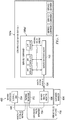
- Figure 4 illustrates a block diagram 400 of interactions between various service orchestration and container management modules/layers (e.g., service orchestration layer 202 and container management layer 204) in an embodiment telecommunications services platform (e.g., telecommunications services platform 106).
- service cluster management is function of service orchestration.
- telecommunications services platform 106 may perform one or more of the following non-limiting functions: service instantiation and configuration, automatically scaling the system based on one or more capacity indicators (e.g., service metrics and/or platform metrics), automatically updating a load balancer pool when new pool members are added or removed, and migrating containers from one host (e.g., a virtual compute node) to another host when a host is overloaded.
- capacity indicators e.g., service metrics and/or platform metrics
- migrating containers from one host e.g., a virtual compute node
- telecommunications services platform 106's service orchestration and container management modules includes a service discovery module 402, a container manager 404, a service configuration module 406, a load monitor 408, a health monitor 410, and an app image repository 412.
- the various modules interact with load balancers in order to manage various service containers 416.
- Load balancers in telecommunications services platform 106 may be interface specific, and telecommunications services platform 106 may include a load balancer 414a for IMS interface, a load balancer 414b for WiFi interface, combinations thereof, and the like.
- a service orchestration layer (e.g., service orchestration layer 202) includes service configuration module 406, service discovery module 402, health monitor 402, and load monitor 404, and these various components may be collectively make up portions of a service orchestrator.
- a container management layer (e.g., container management layer 204) includes container manager 404 and app image repository 412. When new service containers 416 are created and the application comes up successfully (e.g., when the application is initialized and has opened all its interfaces), the service containers 416 register their availability with the service discovery module 402. Each service container 416 may be part of a service cluster to provide a PTT service as described with respect to Figures 2 and 3 , above.
- Service discovery module 402 may also detect when a service container 416 fails. When a new service container 416 is registered, service discovery module 402 executes logic to allow the interfaces of the new service container 416 to be discoverable by the other components (e.g., other containers and modules) in the system. Depending on the service, the discoverability of a new service container may be restricted, by service discovery module 402, to the local site of the new service container, or the discoverability may span across different sites. A more detailed description of service discovery module 402 operations is provided with respect to Figures 5 , 6 , and 7 , below.
- Container manager 404 encapsulates service-specific orchestration logic for various service components in the telecommunications services platform.
- Container manager 404 creates new container instances based on scaling triggers received from load monitor 408 and/or service fault events received from service discovery module 402.
- container manager 404 may also instantiate other containers and configure other services (e.g., load balancers) to support the new service container 416.
- container manager 404 ensures that the service containers 416 of a service cluster are distributed across different compute nodes (e.g., virtual compute nodes 212, see Figure 2 ) in order to provide a desired redundancy.
- container manager 404 may ensure telecommunications services platform provides 'K'-redundancy for each service by ensuring that there are at least 'K' compute node instances available for each service where 'K' is any positive integer.
- Container manager 404 further enforces anti-affinity policies to ensure that container instances that are a part of service cluster are distributed across different virtual machines to provide sufficient redundancy for the service cluster.
- Container manager 404 may also distribute service containers 416 across different available compute nodes (e.g., virtual compute nodes 212, see Figure 2 ) to balance the container load.
- a more detailed description of container manager 404 operations is provided with respect to Figures 8 , 9 , and 10 , below.
- Service configuration module 406 provides a generic template based configuration for various services.
- a new component e.g., a new service container 4166
- the component pulls a required service configuration from a corresponding template of a service cluster the component belongs to.
- all elements in a service cluster may operate using an identical service configuration.
- service configuration module 406 may also ensure that any changes to the service configuration of a service cluster are automatically propagated to all the containers in the service cluster.
- Load monitor 408 is part of the real-time analytics system. Load monitor 408 may use various metrics received from service containers 416 to determine capacity indicators for each service container 416. Load monitor 408 may then generate scaling triggers based on the analysis of these capacity metrics. For some services, capacity indicator metrics may include CPU usage, RAM usage, and the like. Load monitor 408 may also monitor other metrics for services such as media sessions, number of active SIP dialogs, transaction throughput, and the like in order to determine system load.
- Load monitor 408 may also track various virtual machines (e.g., compute nodes) to see if a virtual machine is overloaded due to load skew. When overloading due to load skew is detected, load monitor 408 may trigger container manager 404 to migrate service containers 416 from the overloaded host virtual machine to another virtual machine having spare capacity. In order to support smooth container migration, applications in the service containers 416 may support a drain state in which the applications either: exit gracefully after completing existing tasks, migrating existing tasks, or a combination thereof.
- virtual machines e.g., compute nodes
- Various service containers 416 periodically report their health status to the health monitor 410.
- the services containers 416 may ensure internal subsystems and interfaces in a container are functional by using appropriate internal diagnostic mechanisms.
- health monitor 410 propagates the fault information to service discovery module 402 and container manager 404 in order to trigger various recovery functions. For example, service discovery module 402 may de-register failed instances and create new replacement instances.
- App image repository 412 stores the application container images for various services components. When manifesting a new container instance, a required image is automatically pulled from app image repository 412 for the container.
- a container image repository is a file store from which application images are pulled when creating new container instances.
- the container image repository may be hosted locally in each deployment site as part of the telecommunications services platform.
- FIGS 5 , 6 , and 7 illustrate block diagrams of service discovery module 402 operations according to some embodiments.
- Service discovery module 402 binds various service clusters of the telecommunications services platform (e.g., a PTT platform) together by performing logic to ensure that interfaces of each component (e.g., containers) are discoverable by the other components in the system.
- the discoverability may be restricted to a local site or may span across different deployment sites (e.g., all deployment sites).
- service discovery module 402 includes a service registrar 502, an internal domain name system (DNS) 504, and a health monitor 506, which may be deployed at each deployment site 510.
- Service registrar 502 allows components in the system (e.g., service container instances 508) to register the availability their interfaces to the system.
- Internal DNS 504 exposes interfaces of system components (e.g., as registered with service registrar 502) to the other components across the system.
- Health monitor 506 ensures defunct interfaces (e.g., interfaces of failed components) are timely removed from service registrar 502.
- Service discovery module 402 may include other components as well in other embodiments.
- service registrar 502 is responsible for maintaining a service catalog recording all available service container instances 508 of all services in the system. Whenever are new container is created and the application comes up successfully, the container registers its availability with service registrar 502. When a new container is registered, the service discovery module 402 executes the logic to ensure that all the interfaces of the new container are discoverable by other components (e.g., other containers) in the system through the service catalog and internal DNS 504. Service discovery module 402 may further synchronize the service catalog and other service related information across all deployment sites 510 in the system. For example, service discovery module 402 may synchronize service discovery instances 402' (referred to collectively as a service discovery cluster) across all deployment sites 510. This enables various applications to discover services in any deployment site.
- service discovery module 402 may synchronize service discovery instances 402' (referred to collectively as a service discovery cluster) across all deployment sites 510. This enables various applications to discover services in any deployment site.
- FIG. 6 illustrates a block diagram of internal DNS 504 and service registrar 502 operations according to some embodiments.
- each service in the system is provided with a unique site-level fully qualified domain name (FQDN).
- FQDN format for a service at a deployment site 510 may be "sitel.poccallsvc.kptt-internal.com,” where “site1" identifies the specific deployment site 510, “poccallsvc” identifies the specific service, and "kptt-internal.com” identifies the system domain.
- FQDNs may be derived from a template, such as the above example (e.g., a site identifier.a service identifier.a system domain identifier).
- the system domain identifier is specified as part of system configuration and service identifiers for each service is fixed by design and known by all components. A priori knowledge of various identifiers is used for accessing a service catalog and for service configuration.
- a new service container 508a' associates its interface's IP address with a FQDN of a service cluster 508a, that new service container 508a' belongs to.
- the new service container 508a' may register its interface's IP address with service registrar 502, which adds the IP address with internal DNS 504.
- service registrar 502 adds the IP address with internal DNS 504.
- the interface of new service container 508a' is visible to other service elements, and allows the other service elements to communicate with the new container using DNS lookup.
- a component e.g., service cluster 508b
- a peer component e.g., service cluster 508a
- This transaction is illustrated in Figure 6 as arrows 602 (e.g., querying the internal DNS 504) and arrows 604 (e.g., the returned list of active IP addresses of the peer component).
- the component randomly picks one of the IP addresses from the returned pool of IPs to transmit the message to the peer component as indicated by arrows 606.
- a single service may include multiple interfaces to provide different services or multiple interfaces to provide a same service.
- the service uses a different service FQDN for each of its interfaces and registers all its interfaces with service registrar 502.
- Service discovery module 402 may further automatically remove the IPs of failed components from internal DNS 504 to ensure that no traffic is directed towards an unresponsive or failed component as illustrated by Figure 7 .
- a service discovery agent 702 runs within each service container 508a", and service discovery agent 702 tracks the health status of all internal application modules and resources used within the container.
- Service discovery agent 702 may transmit health status reports to a service health monitor 506 of service discovery module 402 as indicated by arrow 704.
- service health monitor 506 detects a container instance failure (e.g., as indicated by a health status report)
- service health monitor 506 removes the failed container instance from the service catalog through service registrar 502 as indicated by arrow 706.
- Service registrar 502 may then automatically deregister all interfaces of the failed container instance from internal DNS 504 as indicated by arrow 708.
- Service registrar 502 may further report the failed container instance to container manager 404 as indicated by arrow 710.
- the service discovery cluster of service discovery module 402 is initially setup as part of a bootstrap process of the PTT platform.
- Each service discovery component is deployed on a virtual machine cluster hosted on one or more physical processors, which is orchestrated using cloud orchestration APIs.
- the element may be immediately replaced by the cloud virtual machine orchestration layer with a new virtual machine instance to join the cluster.
- the system auto-recovers when the cloud virtual machine orchestration layer spawns replacement virtual machine instances. If all instances of service discovery module 402 fail, the platform may be restarted using a bootstrap procedure, which may be triggered manually (e.g., by a platform operator) or by another system outside of the platform.
- Container management in an embodiment system will be described with respect to Figures 8 , 9 , and 10 below.
- container management involves mapping service workloads (e.g., service containers) to a pool of available virtual machines, which may include different types of virtual machines.
- Distributing service containers across various compute nodes may be in accordance with one or more of the following factors: service affinity constraints, virtual machine server group selection, service bundle management, auto-scaling based on service metrics, minimum and maximum thresholds for number of service container instances, virtual machine resource utilization, anti-affinity rules to spread service container instances evenly across different compute nodes and/or deployment sites, load skew correction, and the like.
- anti-affinity rules that constrain the choice of virtual machine for placing a new container instance may include one or more of the following: virtual machine server group selection, service bundle management, and the like as explained in greater detail below.
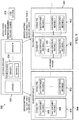
- FIG 8 illustrates a block diagram 800 of mapping service containers to virtual machines 802 according to some embodiments.
- virtual machines 802 are grouped into virtual machine server groups 804.
- Each virtual machine server group 804 may be tuned to provide specific platform characteristics to meet platform requirements of applications (e.g., services encapsulated on containers) running on virtual machines 802 belonging to a respective virtual machine server group 804.
- virtual machine server group 804 include virtual machines 802, which each providing a specific platform characteristic, such as computer processing unit (CPU) resources, network interface resources, block storage type, block storage size, RAM resources, etc.
- the combination of platform characteristics provided by a virtual machine 802 may be referred to as a platform profile.
- Different virtual machine server groups 804 may have different platform profiles.
- container manager 404 places the new container into a virtual machine 802 of an appropriate virtual machine server group 804 having a suitable platform profile for a service cluster to which the new container belongs. For example, container manager 404 maps the new container to a virtual machine 802 belonging to a virtual machine server group 804 having a platform profile providing resources matching a service provided by and/or expected resource usage of a service cluster to which the new container belongs. Within a virtual machine server group 804, container manager 404 may place a new container instance on a least loaded virtual machine 802. In some embodiments, container manager 404 may determine virtual machine loading for each virtual machine 802 based on platform metrics of the respective virtual machine 802. These platform metrics may include one or more of the following: CPU utilization, RAM utilization, disk utilization, network I/O throughput, disk I/O throughout, and the like. Thresholds for these platform metrics may tuned in accordance with each virtual machine server group 804.
- platform metrics may include one or more of the following: CPU utilization, RAM utilization, disk utilization, network I/O throughput, disk I/
- Container manager 404 may map all containers belonging to a service bundle to a same virtual machine and ensure that a desired number of container instances within each service bundle are running at any given time (e.g., as specified by platform configuration).
- the telecommunications services platform may specify configurable thresholds for a minimum and/or a maximum number of container instances for each service to run simultaneously at a deployment site and/or across all deployment sites.
- container manager 404 ensures that a minimum number of container instances are running for each service at any given time, and container manager 404 also ensures that the number of service containers for each service does not exceed a maximum threshold. Thus, a spurious spike on services may not cannibalize resources meant for other services.
- the platform is automatically scaled based on service metrics.
- load monitor 408 uses one or more service metrics to determine the number of container instance required to serve the current load and provides ramp-up/ramp-down triggers to container manager 404.
- Container manager 404 may dynamically spin up and tear down service containers based on triggers provided by load monitor 408.
- container manager 404 may force the service containers into a 'drain' state.
- 'Drain' state is used in various embodiments to facilitate graceful shutdown, container migration, and auto-scale down.
- an application completes currently ongoing transactions and load balancers (e.g., load balancers 414a/414b, see Figure 4 ) stops sending new transactions to the container instance.
- the application may also transfer long running sessions and pending tasks (e.g., Cron, etc) to other container instances.
- the container is given a set time period to complete and/or transfer current tasks to another container before the container is torn down. Thus, task migration may be smoothly handled while supporting container removal.
- container manager 404 may enforce a ramp-down guard timer to ensure the service orchestration layer does not go into oscillation mode due to load fluctuations. For example, container manager 404 may start a ramp-down guard timer after completing a ramp-down, and container manager 404 may not initiate another ramp-down until the ramp-down guard timer expires. Thus, the ramp-down guard timer sets a minimum time between ramp-down periods.
- container manager 404 enforces anti-affinity rules to provide improved service capacity reliability.
- Container manager 404 may attempt to distribute the container instances belonging to a same service evenly across virtual machines 802 of a virtual machine server group 804 having a suitable platform profile. For example, when one or more container instances of a service are running on a first virtual machine, container manager 404 will only place an additional container instance of the same service on the first virtual machine if all other virtual machines in the virtual machine server group have an equal or greater number of container instances for the first service. Thus, failure of a virtual machine instance does not cause a disproportionate drop in the service capacity of a service.
- container manager 404 provides load skew correction.
- load skew correction When services handle sticky sessions, there is a risk of imbalance in platform resource utilization across virtual machines 802 within a virtual machine server group 804. Thus, if one or more virtual machines 802 is getting overloaded (e.g., due to such load skew), container manager 404 may terminate one or more container instances on the overloaded virtual machine to automatically correct the load skew. Container manager 404 may then create new substitute container instances on other less loaded virtual machines 802.
- Figure 9 illustrates container manager 404's response to a failed container instance.
- Container instance failure may be reported to container manager 404 as described above with respect to Figure 7 .
- component failure e.g., container instance failure
- the service orchestration logic removes interface definitions and automatically replaces the failed component with a new container instance 508' as indicated by arrow 902.
- Several containers may fail at the same time (e.g., when a virtual machine 802 hosting the containers fails).
- several virtual machines 802 may fail at the same time (e.g., when a physical host machine dies).
- service orchestration layer 202 may manifest as a container failure to the service orchestration layer 202, and service orchestration layer 202 triggers recovery by instantiating new containers 508' and virtual machines to replace the failed instances. As long as there is sufficient redundancy in the physical infrastructure layer in terms of extra provisioned hardware, service capacity is not significantly diminished by platform component failure.
- container upgrades may begin by uploading an upgraded container image to an app image repository (e.g., app image repository 412).
- Service configuration module 406 may then trigger container upgrades by signaling container manager 404.
- Rolling upgrades may be implemented by forcing a service container 508 into a 'drain' state as described above.
- the container failure recovery logic then replaces the exiting container 508 (e.g., un-upgraded container 508) with a new container instance 508' using the upgraded container image.
- Virtual infrastructure management layer 206 is described in greater detail with respect to Figures 11 and 12 , below.
- Physical infrastructure for hosting a service can be provided by one or more cloud IaaS systems, which could span multiple datacenters (referred to as deployment sites) at different geographical sites.
- Virtual infrastructure management layer 206 provides an abstract interface to the physical cloud infrastructure and serves as the bridge between service orchestration layer 202/container management layer 204 and the physical infrastructure.
- Virtual infrastructure management layer 206 executes scaling triggers received from container management layer 204, and virtual infrastructure management layer 206 uses underlying cloud infrastructure management APIs (e.g. OpenStack) to build up compute nodes with a platform profile (e.g., a requested combination of CPU, RAM, storage and network IO capacity) requested by the container management layer 204.
- cloud infrastructure management APIs e.g. OpenStack
- virtual machines are grouped in to virtual machine server groups 804 within a deployment site 1102.
- each virtual machine server group 804 is tuned to provide platform profiles for applications (e.g., services on containers) running on the virtual machines in the respective virtual machine server group 804.
- platform profiles include parameters and resources such as CPU parameters, block storage parameters, network interface parameters, RAM parameters, combinations thereof, and the like.
- each service in the telecommunications services platform (e.g., a PTT system) is mapped to a specific virtual machine server group 804 based on a function provided by a respective service.
- virtual machine server groups 804 may include management server group, media server group, signaling server group, database server group, demilitarized zone (DMZ) server group, analytics server group, and the like.
- each service cluster in the telecommunications services platform may be mapped to a different virtual machine server group 804.
- a cloud provider may offer host virtual machines 1104 of different flavors, wherein each flavor provides a combination of parameters (e.g., number/type of CPUs, number/type of network interfaces, block storage type, block storage size, RAM size, combinations thereof, and the like).
- These host virtual machines 1104 are instantiated, by the cloud network on physical host processors at deployment sites of physical infrastructure layer 208.
- Virtual machines 802 in each virtual machine server group 804 are mapped to host virtual machines 1104 with a flavor that matching (or most closely matching) a platform profile of a respective virtual machine server group 804.
- design time considerations of the telecommunications services platform may be decoupled from cloud network deployment concerns.
- anti-affinity policies may be enforced by the physical infrastructure layer 208 (e.g., a IaaS layer).
- the physical infrastructure layer may ensure virtual machine instances are spread across different host virtual machines 1104 for improved system resilience.
- the service cluster may still be available.
- Host virtual machines 1104 are operated on the host physical processors in order to provide the functions of service clusters deployed on host virtual machines 1104.
- virtual infrastructure management layer 206 includes a virtual machine cluster manager 1202 and a virtual machine health monitor 1204.
- virtual machine cluster manager 1202 maintains a suitable number of virtual machine instances for each virtual machine server group 804, for example, by signaling virtual machine creation triggers to the physical infrastructure layer 208 (e.g., signaling a IaaS cloud).
- virtual machine cluster manager 1202 determines a number of virtual machine instances needed to each virtual machine server group 804 from virtual machine scaling triggers provided by container manager 404.
- container manager 404 may determine the number of virtual machine instances needed based on desired platform characteristics signaled to container manager 404 from virtual machine server groups 804.
- Virtual machine health monitor 1204 receives health reports from virtual machines in each virtual machine server group 804, and virtual machine health monitor 1204 notifies virtual machine cluster manager 1202 of failed virtual machine instances. Thus, virtual machine cluster manager 1202 may create replacement virtual machine instances based on detected virtual machine instance failure, for example by signaling physical infrastructure layer 208.
- an operating system (OS) image repository 1210 in the telecommunications services platform keeps OS images that are used for spinning up virtual machines in various virtual machine server groups 804.
- OS image repository 1210 When a new image is loaded to OS image repository 1210 by a system administrator (e.g., SysAdmin 1208), OS image repository 1210 will propagate the new image to an OpenStack image repository (e.g., Glance) in the cloud.
- OpenStack image repository e.g., Glance
- virtual machine cluster manager 1202 indicates what image that should be used for the new virtual machines.
- a minimal set of virtual machine instances required for hosting the management layer components are created using cloud orchestration templates, for example.
- the container-based environment described above is used to provide an elastic scalability model for PTT systems.
- service components are implemented as a cluster of application server containers, and the service load is distributed among various cluster elements.
- Various embodiments may support load balancing for different types of traffic in an embodiment telecommunications system.
- application servers may receive one or more of the following types of traffic through one or more interfaces: client/user initiated traffic, peer-to-peer traffic across various components, and asynchronous tasks.
- Client/user initiated traffic may include long sessions such as POC pre-established sessions, short sessions such as PTT calls, transactional load traffic (e.g., data management, presence state updates, etc.), combinations thereof, and the like.
- Peer-to-peer traffic may include traffic between different service components (e.g., between different service clusters, such as between a presence service and a notification service as part of the service execution flow), between same components (e.g., between a same service cluster) to transmit information across stateful sessions managed by different instances (e.g. a PTT call between two clients whose POC pre-established sessions are connected to different PTT servers), combinations thereof, and the like.
- Asynchronous tasks may include session refresh/expiry, data audits, combinations thereof and the like.
- FIG. 13 illustrates a load balancing model 1300 for the client/user initiated traffic in an embodiment PTT system.
- all traffic originating from outside the PTT system may first be dynamically distributed across multiple deployment sites 510, which may be achieved using DNS based global server load balancing (GSLB).
- GSLB global server load balancing
- PTT clients are provided FQDNs to address various services provided by the PTT system.
- a DNS-GSLB 1302 at each deployment site 510 serves as the domain authority for these FQDNs.
- DNS-GSLB 1302 returns an IP address selected for the PTT client based on a configured geographical load distribution policy.
- the geographical load distribution policy may be based on geographic proximity.
- DNS-GSLB 1302 can be configured to direct the traffic to a geographically nearest deployment site 510 based on an originator's IP address.
- the geographical load distribution policy may be based on a weighted round robin policy.
- DNS-GSLB distributes the traffic to various deployment sites 510 in the proportion of the weightage assigned to each site.
- a weight assigned to each of the plurality of geographically diverse deployment sites 510 is proportional to an available spare load bearing capacity of a respective one of the plurality of geographically diverse deployment sites.
- some deployment sites 510 may be larger than the other deployment sites 510.
- Other load distribution policies may also be used in other embodiments.
- the DNS query is performed based on the system receiving a SIP REGISTER request from a PTT client for a PTT session.
- a deployment site 510 is selected for serving the SIP REGISTER request from a PTT client, that deployment site 510 is considered the 'home' site for the duration of the session with the PTT client.
- all services used by the client are provided from the same home site, and a SIP path information may be returned in a REGISTER response to the requesting PTT client.
- the PTT client uses this SIP path information to direct all subsequent SIP service requests to the home site.
- a PTT client may be provided site specific route information as part of the login session establishment procedure for other services.
- each service cluster 1306 includes one or more containers and may provide a different PTT service.
- Application servers on service clusters 1306 may communicate and share information using a common message bus 1308 and distributed database 1310.
- Load balancers 1304 support server stickiness for session based workloads such as POC pre-established sessions, chat group sessions, subscribe dialogs etc.
- load balancers 1304 may keep session based workloads on a same server instance (e.g., a same container instance) when possible.
- Transactional workloads such as messaging, presence updates, and the like may be equally distributed across service clusters 1306.
- load balancing strategies may be used for internal traffic between various elements within a service cluster and between different service clusters.
- the load balancing strategies used by various service components for this type of traffic may include a load balancer proxy, an internal DNS round robin, load balancing through messaging middleware, or a combination thereof.
- An embodiment load balancer proxy may be similar to the PTT client traffic load balancing scheme described above with respect to Figure 5 . Traffic is routed through a load balancing proxy, which distributes the traffic to pool members of the service cluster and also implements session stickiness if desired for that service.
- an internal DNS round robin load balancing scheme is used for internal traffic.
- each service cluster in the PTT platform is provided with unique deployment site level FQDNs.
- An example format for the site level FQDNs may be: "sitel.svcl.kptt-int.com”.
- a new container associates its interface IP address with the FQDN of the container's service cluster.
- the new container element becomes visible to other service elements (e.g., other service clusters), and the container will receive a proportionate share of the peer-to-peer traffic through DNS round robin.
- a component when a component wishes to send a message to a peer component, the component queries an internal DNS (e.g., internal DNS 504, see Figure 6 ) to obtain a list of active IPs for that service and randomly picks one of the IP addresses from the returned pool of IPs.
- An service discovery module e.g., service discovery module 402 may automatically remove the IPs of failed components from the internal DNS and ensures that no traffic is directed towards an unresponsive or failed component.
- load balancing through middleware is used for internal traffic.
- Load balancing through messaging middleware may include service components using a distributed message oriented middleware to obtain benefits of load balancing logic provided by a message bus.
- a service cluster element e.g., service containers
- An embodiment PTT platform may further include an asynchronous task scheduler, which service cluster elements (e.g., service containers) use to schedule tasks for execution at a later time.
- service cluster elements e.g., service containers
- the task may or may not be taken by a same service element that initially scheduled the task. For example, the element that originally scheduled the task may no longer be available, and the service orchestrator has substituted the failed element with a new element.
- any service element capable of performing the scheduled task may take the task from the asynchronous task scheduler.
- the asynchronous task scheduler may distribute scheduled tasks by submitting task details to a suitable service cluster (e.g., using messaging middleware).
- a suitable service cluster e.g., using messaging middleware.
- the load balancing capability of the messaging middleware may be used for asynchronous task load balancing as well.
- service cluster elements may report various metrics for elastic scalability.
- these metrics may include platform metrics, such as CPU usage, RAM usage, network I/O usage of a compute node hosting the service cluster element.
- Service cluster elements in a PTT system may be limited by other service specific capacity constraints.
- each service component may identify such constraints and implements metrics to report the utilization of these service resources.
- Indicators of service capacity may include one or more of the following: number of PTT pre-established sessions, PTT call setup rate, PTT call leg setup rate, number of concurrently active PTT calls, number of concurrently active PTT call legs, number of media codec instances in active use, and the like.
- a service orchestrator may use these service capacity indicators (sometimes referred to as service metrics) to scale service clusters accordingly as described above with respect to Figure 2 .
- Various embodiment telecommunications systems may be equipped to handle deployment site failure.
- deployment site failure For example, disaster situations can cause an entire deployment site to go down. From the service user's perspective, even full site outage may not significantly affect the service availability.
- a deployment site is taken out completely (e.g., deployment site 510a in Figure 14 )
- service traffic is distributed among the other available deployment sites (e.g., deployment sites 510b in Figure 14 ).
- a site outage merely manifests as additional traffic on the remaining sites 510b and does not manifest as complete service failure.
- An embodiment elastic scaling architecture of the telecommunications services system (e.g., the PTT system) is equipped to handle site failure.
- service users maintains simultaneous signaling paths with geographically redundant deployment sites so that the users remain connected to the telecommunications services system when a site failure occurs.
- the user may simultaneously maintain a first signaling path with a first deployment site and a second signaling path with a second deployment site.
- the user transfers active sessions through the second signaling path to the second deployment site.
- These connections may be referred to as geographically redundant signaling paths and allow users to maintain service even during deployment site failure.
- FIG. 15 illustrates a block diagram of a telecommunications system when network partitioning occurs.
- the system has been partitioned.
- deployment site 510c is isolated from deployment sites 510d.
- a service discovery component 402' at deployment site 510c identifies whether deployment site 510c is connected to a majority of the deployment sites (referred to as a majority group).
- service discovery component 402' determines when a partition has occurred when service discovery component 402' loses connectivity with peer service discovery components at other deployment sites. If service discovery component 402' determines deployment site 510c connected to a minority of deployment sites, service discovery component 402' will automatically force deployment site 510c to become dormant. While deployment site 510c is dormant, user traffic is redirected to other deployment sites (e.g., sites 510d) belonging to the majority group.
- the network can be engineered to tolerate a 'K' partition by adding sufficient additional capacity at various deployment sites. For example, when K deployment sites fail simultaneously, the traffic handled by these K failed sites is redistributed equally among the remaining (N-K) deployment sites, where K is the number of sites that are allowed to fail simultaneously under the specified level of redundancy and N is the total number of deployment sites.
- each deployment site is dimensioned to handle a load of L ⁇ 1 + K N ⁇ K , where L represents the amount of traffic that each deployment site is expected to serve when all N sites are available.
- the network may further provide redundant network topology in which deployment sites are connected to each other through multiple paths in order to reduce partitioning.
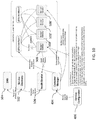
- Figure 16 illustrates an abstract network model 1600 for an embodiment PTT system.
- the PTT system may include different types of network traffic, such as operations, administration, and management (OAM, sometimes referred to as operations, administration, and maintenance) plane traffic 1602, service plane traffic 1604, log plane traffic 1606, and user media plane traffic 1608.
- OAM operations, administration, and management
- SDN log plane traffic
- Various components/services (e.g., as encapsulated in containers) in the PTT system may access different types of network traffic through different virtual network ports.
- virtual infrastructure management accesses OAM plane traffic and log plane traffic
- service management and orchestration accesses OAM plane traffic, service plane traffic, and log plane traffic
- call services access OAM plane traffic, service plane traffic, log plane traffic, and user media plane traffic
- data management services access OAM plane traffic, service plane traffic, and log plane traffic, non-call services access OAM plane traffic, service plane traffic, and log plane traffic
- system monitoring services access OAM plane traffic, service plane traffic, and log plane traffic.
- the various network traffic types accessible to such services may depend on the type of service.
- virtual network ports of containers are used to segregate different types of network traffic received from each plane (also referred to as networks of SDN 1610). These virtual network ports are connected to network ports of a host, that the container is deployed on as illustrated by Figure 17 .
- container network ports 1710 of containers 1704 are connected to host network ports 1702.
- host 1706 e.g., a host virtual machine or baremetal
- the container 1704 is allocated a fixed IP from each network (e.g., SDNs 1610) connected to host 1706.
- Virtual switches 1712 may be used to route traffic between container network ports 1710 and host network ports 1702 using these IP addresses. These IP addresses may be released back to the network when the container 1704 or host 1706 is destroyed.
- One port 1702 is created on the host 1706 for each network (e.g., SDNs 1610) connected to host 1706.
- the mapping of virtual ports used by a container to host network ports may depend on the availability of multiple virtual network interfaces (vNICs) on the flavor of virtual machine hosting the container as provided by the cloud network.
- a telecommunications services platform uses containers to virtualize services provided by the telecommunications services platform.
- Various management layers e.g., a service orchestrator, container manager, and virtual infrastructure manager
- the management layers further map virtual machines to host virtual machines provided by an embodiment cloud network, and the host virtual machines are deployed on physical compute nodes at geographically redundant deployment sites for improved system resilience.
- the cloud network may be independent from or a dedicated entity for the telecommunications services platform.
- a flexible, scalable system may be deployed to provide various telecommunications services (e.g., PTT), and service deployment may be decoupled from physical infrastructure deployment.
- FIG. 18 illustrates a block diagram of an embodiment processing system 1800 for performing methods described herein, which may be installed in a host device.
- the processing system 1800 includes a processor 1804, a memory 1806, and interfaces 1810-1814, which may (or may not) be arranged as shown in FIG. 18 .
- the processor 1804 may be any component or collection of components adapted to perform computations and/or other processing related tasks
- the memory 1806 may be any component or collection of components adapted to store programming and/or instructions for execution by the processor 1804.
- the memory 1806 includes a non-transitory computer readable medium.
- the interfaces 1810, 1812, 1814 may be any component or collection of components that allow the processing system 1800 to communicate with other devices/components and/or a user.
- one or more of the interfaces 1810, 1812, 1814 may be adapted to communicate data, control, or management messages from the processor 1804 to applications installed on the host device and/or a remote device.
- one or more of the interfaces 1810, 1812, 1814 may be adapted to allow a user or user device (e.g., personal computer (PC), etc.) to interact/communicate with the processing system 1800.
- the processing system 1100 may include additional components not depicted in FIG. 18 , such as long term storage (e.g., non-volatile memory, etc.).
- the processing system 1800 is included in a network device that is accessing, or part otherwise of, a telecommunications network.
- the processing system 1800 is in a network-side device in a wireless or wireline telecommunications network, such as a base station, a relay station, a scheduler, a controller, a gateway, a router, an applications server, or any other device in the telecommunications network.
- the processing system 1800 is in a user-side device accessing a wireless or wireline telecommunications network, such as a mobile station, a user equipment (UE), a personal computer (PC), a tablet, a wearable communications device (e.g., a smartwatch, etc.), or any other device adapted to access a telecommunications network.
- a wireless or wireline telecommunications network such as a mobile station, a user equipment (UE), a personal computer (PC), a tablet, a wearable communications device (e.g., a smartwatch, etc.), or any other device adapted to access a telecommunications network.
- FIG. 19 illustrates a block diagram of a transceiver 1900 adapted to transmit and receive signaling over a telecommunications network.
- the transceiver 1900 may be installed in a host device. As shown, the transceiver 1900 comprises a network-side interface 1902, a coupler 1904, a transmitter 1906, a receiver 1908, a signal processor 1910, and a device-side interface 1912.
- the network-side interface 1902 may include any component or collection of components adapted to transmit or receive signaling over a wireless or wireline telecommunications network.
- the coupler 1904 may include any component or collection of components adapted to facilitate bi-directional communication over the network-side interface 1902.
- the transmitter 1906 may include any component or collection of components (e.g., up-converter, power amplifier, etc.) adapted to convert a baseband signal into a modulated carrier signal suitable for transmission over the network-side interface 1902.
- the receiver 1908 may include any component or collection of components (e.g., down-converter, low noise amplifier, etc.) adapted to convert a carrier signal received over the network-side interface 1902 into a baseband signal.
- the signal processor 1910 may include any component or collection of components adapted to convert a baseband signal into a data signal suitable for communication over the device-side interface(s) 1912, or vice-versa.
- the device-side interface(s) 1912 may include any component or collection of components adapted to communicate data-signals between the signal processor 1910 and components within the host device (e.g., the processing system 1100, local area network (LAN) ports, etc.
- the transceiver 1900 may transmit and receive signaling over any type of communications medium.
- the transceiver 1900 transmits and receives signaling over a wireless medium.
- the transceiver 1900 may be a wireless transceiver adapted to communicate in accordance with a wireless telecommunications protocol, such as a cellular protocol (e.g., long-term evolution (LTE), etc.), a wireless local area network (WLAN) protocol (e.g., Wi-Fi, etc.), or any other type of wireless protocol (e.g., Bluetooth, near field communication (NFC), etc.).
- the network-side interface 1902 comprises one or more antenna/radiating elements.
- the network-side interface 1902 may include a single antenna, multiple separate antennas, or a multi-antenna array configured for multi-layer communication, e.g., single input multiple output (SIMO), multiple input single output (MISO), multiple input multiple output (MIMO), etc.
- the transceiver 1900 transmits and receives signaling over a wireline medium, e.g., twisted-pair cable, coaxial cable, optical fiber, etc.
- Specific processing systems and/or transceivers may utilize all of the components shown, or only a subset of the components, and levels of integration may vary from device to device.
- a method includes triggering, by a service orchestrator hosted on a processor, creation of one or more container instances for a first service cluster.
- the first service cluster provides a first service for a telecommunications services platform.
- the method further includes creating, by a container manager hosted on a processor, the one or more container instances and mapping, by the container manager, the one or more container instances of the first service cluster to one or more first virtual machines belonging to a first virtual machine server group in accordance with a platform profile of the first virtual machine server group and the first service provided by the first service cluster.
- the method further includes mapping, by a virtual machine manager hosted on a processor, the one or more first virtual machines to one or more first host virtual machines of a cloud network in accordance with the platform profile of the first virtual machine server group.
- the method further includes deploying the one or more first host virtual machines on one or more host processors.
- the platform profile includes computer processing unit (CPU) parameters, network interface parameters, block storage parameters, random access memory parameters, or a combination thereof provided by each of the one or more first virtual machines belonging to the first virtual machine server group.
- CPU computer processing unit
- the method further includes registering the one or more container instances with a service registrar and adding, by the service registrar, internet protocol (IP) addresses for interfaces of the one or more container instances with a domain name system (DNS).
- IP internet protocol
- DNS domain name system
- the IP addresses for the interfaces of the one or more container instances are each in accordance with a fully qualified domain name (FQDN) of the first service, and the interfaces of the one or more container instances are discoverable by other components of the telecommunications services platform by performing a DNS search on the FQDN.
- the method may further include restricting discovery of the interfaces of the one or more container instances to components of the telecommunications services platform deployed on processors located at a same deployment site as the one or more host processors.
- the other components of the telecommunications services platform are deployed across all deployment sites of the telecommunications services platform.
- the method further includes ensuring, by the container manager, at least a minimum number of virtual machines are available in the first virtual machine server group for the first service cluster.
- mapping the one or more container instances to the one or more first virtual machines includes mapping the one or more container instances to the one or more first virtual machines in accordance with an anti-affinity policy.
- the anti-affinity policy includes mapping a first one of the one or more container instances to a first one of the one or more first virtual machines and mapping a second container instance of the first service cluster to the first one of the one or more first virtual machines only when all virtual machines belonging to the first virtual machine server group host at least as many container instances for the first service cluster as the first one of the one or more first virtual machines.
- the method further includes bundling a first one of the one or more container instances with a second container instance and mapping the second container instance to a same one of the one or more first virtual machines as the first one of the one or more container instances.
- the second container instance belongs to a different service cluster than the first service cluster.
- the different service cluster provides a second service for the telecommunications services platform different than the first service.
- the method further includes triggering, by the service orchestrator, a ramp down of container instances in accordance with one or more service metrics of the telecommunications services platform and removing, by the container manager, one or more second container instances in accordance with a ramp down trigger received from the service orchestrator.
- the method further includes forcing, by the container manager, the one or more second container instances into a drain state before removing the one or more second container instances and after receiving the ramp down trigger.
- a container completes ongoing transactions or transfers sessions and pending transactions to a different container when the container is in the drain state.
- a load balancer stops sending new transactions to the container when the container is in the drain state.
- the method further includes forcing, by the container manager, a container instance into the drain state when the container manager updates the container instance.
- the method further includes setting, by the container manager, a ramp down guard timer when the one or second container instances are removed and not removing, by the container manager, any additional container instances in accordance with another ramp down trigger until the ramp down guard timer expires.
- the method further includes determining, by the container manager, when a first one of the one or more first virtual machines is overloaded due to load skew, removing, by the container manager, a first one of the one or more container instances on the first one of the one or more first virtual machines, and creating, by the container manager, a replacement container instance for the first service cluster on a different virtual machine belonging to the first virtual machine server group to replace the first one of the one or more container instances.
- the method further includes grouping virtual machines in the telecommunications services platform into virtual machine server groups in accordance with platform parameters provided by each of the virtual machines.
- Each virtual machine server group has a different platform profile.
- each service provided by the telecommunications services platform is mapped to a different virtual machine server group.
- mapping the one or more virtual machines to one or more host virtual machines of a cloud network in accordance with the platform profile of the first virtual machine server group comprises mapping the one or more virtual machines to one or more host virtual machines providing platform characteristics best matching the platform profile of the first virtual machine server group compared to other types of host virtual machines provided by the cloud network.
- a method includes triggering, by a processor, creation of one or more container instances for a first service cluster.
- the first service cluster is one of a plurality of service clusters in a push-to-talk (PTT) platform, and each of the plurality of service clusters provides a different function for the PTT platform.
- the method further includes creating, by a processor, the one or more container instances and mapping, by a processor, the one or more container instances of the first service cluster to one or more first virtual machines belonging to a first virtual machine server group in accordance with a platform profile of the first virtual machine server group and a first PTT function provided by the first service cluster.
- the method further includes mapping, by a virtual machine manager hosted on a processor, the one or more virtual machines to one or more first host virtual machines of a cloud network in accordance with the platform profile of the first virtual machine server group.
- the cloud network is deployed independently from the PTT platform.
- the method further includes operating the one or more first host virtual machines on one or more host processors to provide the first PTT function for the PTT platform.
- the method further includes directing traffic originating from a PTT client on a user equipment (UE) to a deployment site in accordance with a geographic proximity of the deployment site to the UE.
- UE user equipment
- the method further includes traffic originating from a PTT client on a user equipment (UE) to a deployment site in accordance with a weighted round-robin load balancing policy.
- UE user equipment
- the method further includes receiving a registration request from a PTT client on a user equipment (UE) and selecting a deployment site for the registration request. All subsequent session initial protocol (SIP) service requests for the PTT client are directed to the deployment site.
- SIP session initial protocol
- the method further includes supporting, by a load balancer hosted on a processor, container instance-stickiness for session based workloads of a PTT client on a user equipment (UE).
- UE user equipment
- triggering the creation of one or more container instances for a first service cluster is in accordance with one or more service metrics.
- the one or more service metrics comprises number of push-to-talk (PTT) pre-established sessions, PTT call setup rate, PTT call leg setup rate, number of concurrently active PTT calls, number of concurrently active PTT call legs, number of media codec instances in active use, or a combination thereof.
- PTT push-to-talk
- the method further includes maintaining a first signaling path between a PTT client on a user equipment (UE) and a first deployment site of the PTT platform, maintaining a second signaling path between the PTT client and a second deployment site of the PTT platform.
- the first signaling path and the second signaling path are maintained simultaneously, and the first deployment site is at a different geographic location than the second deployment site.
- the method further includes transferring active sessions of the PTT client using the second signaling path when the first deployment site fails.
- the method further includes detecting, by a service discovery mechanism, a first deployment site of the PTT platform is partitioned from one or more second deployment sites of the PTT platform, determining, by the service discovery mechanism, one or more third deployment sites connected the first deployment site after the first deployment site is partitioned, and forcing, by the service discovery mechanism, the first deployment site into a dormant state when the one or more third deployment sites and the first deployment site do not account for a majority of deployment sites in the PTT platform.
- the method further includes transferring traffic from the first deployment site to the one or more second deployment sites when the first deployment site is in the dormant state.
- a telecommunications services platform including: one or more processors and one or more computer readable storage mediums storing programming for execution by the one or more processors.
- the programming includes instructions to trigger, by a service orchestrator, creation of one or more container instances for a service cluster.
- the service cluster provides a function for the telecommunications services platform.
- the programming includes further instructions to create, by a container manager, the one or more container instances and map, by the container manager, the one or more container instances of the service cluster to one or more virtual machines belonging to a virtual machine server group in accordance with a platform profile of the virtual machine server group and the function provided by the service cluster.
- the programming includes further instructions to map, by a virtual machine manager hosted on a processor, the one or more virtual machines to one or more host virtual machines of a cloud network in accordance with the platform profile of the virtual machine server group and operate the one or more host virtual machines to provide the function for the telecommunications services platform.
- each of the one or more host virtual machines comprise a plurality of first network ports, and each of the plurality of first network ports provides a connections to a different type of network traffic.
- each of the one or more container instances comprises a plurality of second network ports, and each of the one or more host virtual machines comprises one or more virtual network switches to route traffic between the plurality of first network ports and the plurality of second network ports.
Landscapes
- Engineering & Computer Science (AREA)
- Computer Networks & Wireless Communication (AREA)
- Signal Processing (AREA)
- Multimedia (AREA)
- Software Systems (AREA)
- Theoretical Computer Science (AREA)
- General Engineering & Computer Science (AREA)
- Business, Economics & Management (AREA)
- General Business, Economics & Management (AREA)
- Physics & Mathematics (AREA)
- General Physics & Mathematics (AREA)
- Computer Hardware Design (AREA)
- Data Exchanges In Wide-Area Networks (AREA)
- Telephonic Communication Services (AREA)
- Management, Administration, Business Operations System, And Electronic Commerce (AREA)
Claims (31)
- Procédé comprenant les étapes ci-dessous consistant à :déclencher, par le biais d'un orchestrateur de services (202) hébergé sur un processeur, la création d'une ou plusieurs instances de conteneurs pour une première grappe de services (210), dans lequel la première grappe de services (210) fournit un premier service pour une plateforme de services de télécommunication ;créer, par le biais d'un gestionnaire de conteneurs (204) hébergé sur un processeur, ladite une ou lesdites plusieurs instances de conteneurs ;mettre en correspondance, par le biais du gestionnaire de conteneurs (204), ladite une ou lesdites plusieurs instances de conteneurs de la première grappe de services (210), avec une ou plusieurs premières machines virtuelles appartenant à un premier groupe de serveurs de machines virtuelles conformément à un profil de plateforme du premier groupe de serveurs de machines virtuelles et au premier service fourni par la première grappe de services ;mettre en correspondance, par le biais d'un gestionnaire de machines virtuelles (206) hébergé sur un processeur, ladite une ou lesdites plusieurs premières machines virtuelles, avec une ou plusieurs premières machines virtuelles hôtes d'un réseau infonuagique conformément au profil de plateforme du premier groupe de serveurs de machines virtuelles ; etdéployer ladite une ou lesdites plusieurs premières machines virtuelles hôtes sur un ou plusieurs processeurs hôtes.
- Procédé selon la revendication 1, dans lequel le profil de plateforme comprend des paramètres d'unité centrale de traitement, CPU, des paramètres d'interface réseau, des paramètres de mémoire de blocs, des paramètres de mémoire vive, ou une combinaison de ceux-ci, fournis par chacune de ladite une ou desdites plusieurs premières machines virtuelles appartenant au premier groupe de serveurs de machines virtuelles.
- Procédé selon la revendication 1, comprenant en outre les étapes ci-dessous consistant à :enregistrer ladite une ou lesdites plusieurs instances de conteneurs auprès d'un registre de services (302b, 502) ; etajouter, par le biais du registre de services (302b, 502), des adresses de protocole Internet, IP, pour des interfaces de ladite une ou desdites plusieurs instances de conteneurs avec un système de noms de domaine, DNS, dans lequel les adresses IP pour les interfaces de ladite une ou desdites plusieurs instances de conteneurs sont chacune conformes à un nom de domaine totalement qualifié, FQDN, du premier service, et dans lequel les interfaces de ladite une ou desdites plusieurs instances de conteneurs peuvent être découvertes par d'autres composants de la plateforme de services de télécommunication en mettant en œuvre une recherche DNS sur le nom de domaine FQDN.
- Procédé selon la revendication 3, comprenant en outre l'étape consistant à limiter la découverte des interfaces de ladite une ou desdites plusieurs instances de conteneurs à des composants de la plateforme de services de télécommunication déployés sur des processeurs situés sur un même site de déploiement que ledit un ou lesdits plusieurs processeurs hôtes.
- Procédé selon la revendication 3, dans lequel les autres composants de la plateforme de services de télécommunication sont déployés sur tous les sites de déploiement de la plateforme de services de télécommunication.
- Procédé selon la revendication 1, comprenant en outre l'étape consistant à garantir, par le biais du gestionnaire de conteneurs (204), qu'au moins un nombre minimum de machines virtuelles est disponible dans le premier groupe de serveurs de machines virtuelles pour la première grappe de services.
- Procédé selon la revendication 1, dans lequel l'étape de mise en correspondance de ladite une ou desdites plusieurs instances de conteneurs avec ladite une ou lesdites plusieurs premières machines virtuelles consiste à mettre en correspondance ladite une ou lesdites plusieurs instances de conteneurs avec ladite une ou lesdites plusieurs premières machines virtuelles conformément à une politique d'anti-affinité.
- Procédé selon la revendication 7, dans lequel la politique d'anti-affinité comprend les étapes ci-dessous consistant à :mettre en correspondance une première instance de ladite une ou desdites plusieurs instances de conteneurs avec une première machine de ladite une ou desdites plusieurs premières machines virtuelles ; etmettre en correspondance une seconde instance de conteneur de la première grappe de services avec la première machine de ladite une ou desdites plusieurs premières machines virtuelles, uniquement lorsque toutes les machines virtuelles appartenant au premier groupe de serveurs de machines virtuelles hébergent au moins autant d'instances de conteneurs pour la première grappe de services que la première machine de ladite une ou desdites plusieurs premières machines virtuelles.
- Procédé selon la revendication 1, comprenant en outre les étapes ci-dessous consistant à :grouper une première instance de ladite une ou desdites plusieurs instances de conteneurs avec une seconde instance de conteneur, dans lequel la seconde instance de conteneur appartient à une grappe de services différente de la première grappe de services, dans lequel la grappe de services différente fournit un second service, pour la plateforme de services de télécommunication, différent du premier service ; etmettre en correspondance la seconde instance de conteneur avec une machine virtuelle, parmi ladite une ou lesdites plusieurs premières machines virtuelles, identique à la première instance de ladite une ou desdites plusieurs instances de conteneurs.
- Procédé selon la revendication 1, comprenant en outre les étapes ci-dessous consistant à :déclencher, par le biais de l'orchestrateur de services (202), une diminution progressive d'instances de conteneurs conformément à une ou plusieurs métriques de services de la plateforme de services de télécommunication ; etsupprimer, par le biais du gestionnaire de conteneurs (204), une ou plusieurs secondes instances de conteneurs conformément à un déclencheur de diminution progressive reçu en provenance de l'orchestrateur de services (202).
- Procédé selon la revendication 10, comprenant en outre l'étape consistant à forcer, par le biais du gestionnaire de conteneurs (204), ladite une ou lesdites plusieurs secondes instances de conteneurs dans un état de vidage, avant de supprimer ladite une ou lesdites plusieurs secondes instances de conteneurs et après avoir reçu le déclencheur de diminution progressive.
- Procédé selon la revendication 11, dans lequel un conteneur achève des opérations transactionnelles en cours, ou transfère des sessions et des opérations transactionnelles en attente vers un conteneur différent lorsque le conteneur est à l'état de vidage, et dans lequel un équilibreur de charge met fin à l'envoi de nouvelles opérations transactionnelles au conteneur lorsque le conteneur est à l'état de vidage.
- Procédé selon la revendication 11, comprenant en outre l'étape consistant à forcer, par le biais du gestionnaire de conteneurs (204), une instance de conteneur dans l'état de vidage lorsque le gestionnaire de conteneurs met à jour l'instance de conteneur.
- Procédé selon la revendication 10, comprenant en outre les étapes ci-dessous consistant à :définir, par le biais du gestionnaire de conteneurs (204), un temporisateur de garde de diminution progressive lorsque ladite une ou lesdites plusieurs secondes instances de conteneurs sont supprimées ; etne pas supprimer, par le biais du gestionnaire de conteneurs (204), d'instances de conteneurs supplémentaires quelconques conformément à un autre déclencheur de diminution progressive, jusqu'à l'expiration du temporisateur de garde de diminution progressive.
- Procédé selon la revendication 1, comprenant en outre les étapes ci-dessous consistant à :déterminer, par le biais du gestionnaire de conteneurs (204), le moment où une première machine de ladite une ou desdites plusieurs premières machines virtuelles est surchargée sous l'effet d'un effet d'obliquité de charge ;supprimer, par le biais du gestionnaire de conteneurs (204), une première instance de ladite une ou desdites plusieurs instances de conteneurs sur la première machine de ladite une ou desdites plusieurs premières machines virtuelles ; etcréer, par le biais du gestionnaire de conteneurs (204), une instance de conteneur de remplacement pour la première grappe de services sur une machine virtuelle différente appartenant au premier groupe de serveurs de machines virtuelles en vue de remplacer la première instance de ladite une ou desdites plusieurs instances de conteneurs.
- Procédé selon la revendication 1, comprenant en outre l'étape consistant à regrouper des machines virtuelles dans la plateforme de services de télécommunication en des groupes de serveurs de machines virtuelles conformément à des paramètres de plateforme fournis par chacune des machines virtuelles, dans lequel chaque groupe de serveurs de machines virtuelles présente un profil de plateforme différent.
- Procédé selon la revendication 16, dans lequel chaque service fourni par la plateforme de services de télécommunication est mis en correspondance avec un groupe de serveurs de machines virtuelles différent.
- Procédé selon la revendication 1, dans lequel l'étape de mise en correspondance de ladite une ou desdites plusieurs machines virtuelles avec une ou plusieurs machines virtuelles hôtes d'un réseau infonuagique, conformément au profil de plateforme du premier groupe de serveurs de machines virtuelles, consiste à mettre en correspondance ladite une ou lesdites plusieurs machines virtuelles avec une ou plusieurs machines virtuelles hôtes fournissant des caractéristiques de plateforme correspondant le mieux au profil de plateforme du premier groupe de serveurs de machines virtuelles par rapport à d'autres types de machines virtuelles hôtes fournies par le réseau infonuagique.
- Procédé comprenant les étapes ci-dessous consistant à :déclencher, par le biais d'un processeur, la création d'une ou plusieurs instances de conteneurs pour une première grappe de services (210), dans lequel la première grappe de services (210) correspond à l'une d'une pluralité de grappes de services dans une plateforme de messagerie instantanée vocale (PTT), et dans lequel chaque grappe de la pluralité de grappes de services fournit une fonction différente pour la plateforme de messagerie PTT ;créer, par le biais d'un processeur, ladite une ou lesdites plusieurs instances de conteneurs ;mettre en correspondance, par le biais d'un processeur, ladite une ou lesdites plusieurs instances de conteneurs de la première grappe de services (210), avec une ou plusieurs premières machines virtuelles appartenant à un premier groupe de serveurs de machines virtuelles conformément à un profil de plateforme du premier groupe de serveurs de machines virtuelles et à une première fonction de messagerie PTT fournie par la première grappe de services ;mettre en correspondance, par le biais d'un gestionnaire de machines virtuelles (206) hébergé sur un processeur, ladite une ou lesdites plusieurs premières machines virtuelles, avec une ou plusieurs premières machines virtuelles hôtes d'un réseau infonuagique conformément au profil de plateforme du premier groupe de serveurs de machines virtuelles, dans lequel le réseau infonuagique est déployé indépendamment de la plateforme de messagerie PTT ; etexploiter ladite une ou lesdites plusieurs premières machines virtuelles hôtes sur un ou plusieurs processeurs hôtes pour fournir la première fonction de messagerie PTT pour la plateforme de messagerie PTT.
- Procédé selon la revendication 19, comprenant en outre l'étape consistant à diriger le trafic provenant d'un client de messagerie PTT sur un équipement d'utilisateur, UE, vers un site de déploiement conformément à une proximité géographique du site de déploiement par rapport à l'équipement UE.
- Procédé selon la revendication 19, comprenant en outre l'étape consistant à diriger le trafic provenant d'un client de messagerie PTT sur un équipement d'utilisateur, UE, vers un site de déploiement conformément à une politique d'équilibrage de charge par ordonnancement cyclique avec pondération.
- Procédé selon la revendication 19, comprenant en outre les étapes ci-dessous consistant à :recevoir une demande d'enregistrement en provenance d'un client de messagerie PTT sur un équipement d'utilisateur, UE ; etsélectionner un site de déploiement pour la demande d'enregistrement, dans lequel toutes les demandes de service de protocole d'ouverture de session, SIP, subséquentes pour le client de messagerie PTT sont dirigées vers le site de déploiement.
- Procédé selon la revendication 19, comprenant en outre l'étape consistant à prendre en charge, par le biais d'un équilibreur de charge hébergé sur un processeur, une adhérence d'instance de conteneur, pour des charges de travail à base de session d'un client de messagerie PTT sur un équipement d'utilisateur, UE.
- Procédé selon la revendication 19, dans lequel l'étape de déclenchement de la création d'une ou plusieurs instances de conteneurs pour une première grappe de services est conforme à une ou plusieurs métriques de service, dans lequel ladite une ou lesdites plusieurs métriques de services comprennent un nombre de sessions préétablies de messagerie instantanée vocale, PTT, un taux d'établissement d'appels de messagerie PTT, un taux d'établissement de branches d'appel de messagerie PTT, un nombre d'appels de messagerie PTT actifs simultanément, un nombre de branches d'appel de messagerie PTT actives simultanément, un nombre d'instances de codecs multimédias en utilisation active, ou une combinaison de ceux-ci.
- Procédé selon la revendication 19, comprenant en outre les étapes ci-dessous consistant à :maintenir un premier chemin de signalisation entre un client de messagerie PTT sur un équipement d'utilisateur, UE, et un premier site de déploiement de la plateforme de messagerie PTT ; etmaintenir un second chemin de signalisation entre le client de messagerie PTT et un deuxième site de déploiement de la plateforme de messagerie PTT, dans lequel le premier chemin de signalisation et le second chemin de signalisation sont maintenus simultanément, et dans lequel le premier site de déploiement se situe à un emplacement géographique différent de celui du deuxième site de déploiement.
- Procédé selon la revendication 25, comprenant en outre l'étape consistant à transférer des sessions actives du client de messagerie PTT en utilisant le second chemin de signalisation lorsque le premier site de déploiement est défaillant.
- Procédé selon la revendication 19, comprenant en outre les étapes ci-dessous consistant à :détecter, par le biais d'un mécanisme de découverte de services (402), qu'un premier site de déploiement de la plateforme de messagerie PTT est partitionné à partir d'un ou plusieurs deuxièmes sites de déploiement de la plateforme de messagerie PTT ;déterminer, par le biais du mécanisme de découverte de services, un ou plusieurs troisièmes sites de déploiement connectés au premier site de déploiement après que le premier site de déploiement a été partitionné ; etforcer, par le biais du mécanisme de découverte de services (402), le premier site de déploiement vers un état dormant, lorsque ledit un ou lesdits plusieurs troisièmes sites de déploiement et le premier site de déploiement ne représentent pas la majorité des sites de déploiement de la plateforme de messagerie PTT.
- Procédé selon la revendication 27, comprenant en outre l'étape consistant à transférer du trafic du premier site de déploiement vers ledit un ou lesdits plusieurs deuxièmes sites de déploiement lorsque le premier site de déploiement est à l'état dormant.
- Plateforme de services de télécommunication comprenant :un ou plusieurs processeurs ; etun support de stockage lisible par ordinateur stockant un programme à des fins d'exécution par ledit un ou lesdits plusieurs processeurs, le programme incluant des instructions pour :déclencher, par le biais d'un orchestrateur de services, la création d'une ou plusieurs instances de conteneurs pour une grappe de services, dans lequel la grappe de services fournit une fonction pour une plateforme de services de télécommunication ;créer, par le biais d'un gestionnaire de conteneurs (204), ladite une ou lesdites plusieurs instances de conteneurs ;mettre en correspondance, par le biais du gestionnaire de conteneurs (204), ladite une ou lesdites plusieurs instances de conteneurs de la grappe de services, avec une ou plusieurs machines virtuelles appartenant à un groupe de serveurs de machines virtuelles conformément à un profil de plateforme du groupe de serveurs de machines virtuelles et à la fonction fournie par la grappe de services ;mettre en correspondance, par le biais d'un gestionnaire de machines virtuelles hébergé sur un processeur, ladite une ou lesdites plusieurs machines virtuelles, avec une ou plusieurs machines virtuelles hôtes d'un réseau infonuagique conformément au profil de plateforme du groupe de serveurs de machines virtuelles ; etexploiter ladite une ou lesdites plusieurs machines virtuelles hôtes pour fournir la fonction pour la plateforme de services de télécommunication.
- Plateforme de services de télécommunication selon la revendication 29, dans laquelle chaque machine parmi ladite une ou lesdites plusieurs machines virtuelles hôtes comprend une pluralité de premiers ports de réseau, dans lequel chaque port de la pluralité de premiers ports de réseau fournit une connexion à un type différent de trafic de réseau.
- Plateforme de services de télécommunication selon la revendication 30, dans laquelle chaque instance parmi ladite une ou lesdites plusieurs instances de conteneurs comprend une pluralité de seconds ports de réseau, et dans laquelle chaque machine parmi ladite une ou lesdites plusieurs machines virtuelles hôtes comprend un ou plusieurs commutateurs de réseau virtuel pour acheminer du trafic entre la pluralité de premiers ports de réseau et la pluralité de seconds ports de réseau.
Applications Claiming Priority (4)
| Application Number | Priority Date | Filing Date | Title |
|---|---|---|---|
| US201562103404P | 2015-01-14 | 2015-01-14 | |
| US201562111414P | 2015-02-03 | 2015-02-03 | |
| US14/994,757 US9462427B2 (en) | 2015-01-14 | 2016-01-13 | System and method for elastic scaling using a container-based platform |
| PCT/US2016/013443 WO2016115371A1 (fr) | 2015-01-14 | 2016-01-14 | Système et procédé de mise à l'échelle élastique à l'aide d'une plateforme à base de conteneur |
Publications (3)
| Publication Number | Publication Date |
|---|---|
| EP3245596A1 EP3245596A1 (fr) | 2017-11-22 |
| EP3245596A4 EP3245596A4 (fr) | 2018-10-17 |
| EP3245596B1 true EP3245596B1 (fr) | 2020-08-12 |
Family
ID=56368474
Family Applications (2)
| Application Number | Title | Priority Date | Filing Date |
|---|---|---|---|
| EP16737894.2A Active EP3245596B1 (fr) | 2015-01-14 | 2016-01-14 | Système et procédé de mise à l'échelle élastique à l'aide d'une plateforme à base de conteneur |
| EP16737897.5A Active EP3245578B1 (fr) | 2015-01-14 | 2016-01-14 | Système et procédé de mise à l'échelle élastique dans une plateforme de messagerie vocale instantanée (ptt) à l'aide de groupes d'affinités d'utilisateur |
Family Applications After (1)
| Application Number | Title | Priority Date | Filing Date |
|---|---|---|---|
| EP16737897.5A Active EP3245578B1 (fr) | 2015-01-14 | 2016-01-14 | Système et procédé de mise à l'échelle élastique dans une plateforme de messagerie vocale instantanée (ptt) à l'aide de groupes d'affinités d'utilisateur |
Country Status (5)
| Country | Link |
|---|---|
| US (2) | US9775008B2 (fr) |
| EP (2) | EP3245596B1 (fr) |
| CA (2) | CA2970824C (fr) |
| MX (2) | MX2017009075A (fr) |
| WO (2) | WO2016115374A1 (fr) |
Cited By (2)
| Publication number | Priority date | Publication date | Assignee | Title |
|---|---|---|---|---|
| US11323511B2 (en) * | 2019-04-09 | 2022-05-03 | T-Mobile Usa, Inc. | Migrating a network service to a container-based platform |
| US12160340B2 (en) | 2021-05-26 | 2024-12-03 | Red Hat, Inc. | Adding host systems to existing containerized clusters |
Families Citing this family (193)
| Publication number | Priority date | Publication date | Assignee | Title |
|---|---|---|---|---|
| US8837465B2 (en) | 2008-04-02 | 2014-09-16 | Twilio, Inc. | System and method for processing telephony sessions |
| EP2266269B1 (fr) | 2008-04-02 | 2019-01-02 | Twilio Inc. | Système et procédé destinés au traitement de sessions de téléphonie |
| EP2335402A4 (fr) | 2008-10-01 | 2013-04-24 | Twilio Inc | Système et procédé d'événement web téléphonique |
| JP5671484B2 (ja) | 2009-03-02 | 2015-02-18 | トゥイリオ インコーポレイテッドTwilio Inc. | マルチテナント電話ネットワークのための方法およびシステム |
| US9210275B2 (en) | 2009-10-07 | 2015-12-08 | Twilio, Inc. | System and method for running a multi-module telephony application |
| US20120208495A1 (en) | 2010-06-23 | 2012-08-16 | Twilio, Inc. | System and method for monitoring account usage on a platform |
| US9590849B2 (en) | 2010-06-23 | 2017-03-07 | Twilio, Inc. | System and method for managing a computing cluster |
| US8838707B2 (en) | 2010-06-25 | 2014-09-16 | Twilio, Inc. | System and method for enabling real-time eventing |
| US8649268B2 (en) | 2011-02-04 | 2014-02-11 | Twilio, Inc. | Method for processing telephony sessions of a network |
| US20140044123A1 (en) | 2011-05-23 | 2014-02-13 | Twilio, Inc. | System and method for real time communicating with a client application |
| US9648006B2 (en) | 2011-05-23 | 2017-05-09 | Twilio, Inc. | System and method for communicating with a client application |
| US9398622B2 (en) | 2011-05-23 | 2016-07-19 | Twilio, Inc. | System and method for connecting a communication to a client |
| US10182147B2 (en) | 2011-09-21 | 2019-01-15 | Twilio Inc. | System and method for determining and communicating presence information |
| US9495227B2 (en) | 2012-02-10 | 2016-11-15 | Twilio, Inc. | System and method for managing concurrent events |
| US9602586B2 (en) | 2012-05-09 | 2017-03-21 | Twilio, Inc. | System and method for managing media in a distributed communication network |
| US9247062B2 (en) | 2012-06-19 | 2016-01-26 | Twilio, Inc. | System and method for queuing a communication session |
| US8737962B2 (en) | 2012-07-24 | 2014-05-27 | Twilio, Inc. | Method and system for preventing illicit use of a telephony platform |
| US8938053B2 (en) | 2012-10-15 | 2015-01-20 | Twilio, Inc. | System and method for triggering on platform usage |
| US8948356B2 (en) | 2012-10-15 | 2015-02-03 | Twilio, Inc. | System and method for routing communications |
| US9282124B2 (en) | 2013-03-14 | 2016-03-08 | Twilio, Inc. | System and method for integrating session initiation protocol communication in a telecommunications platform |
| US9240966B2 (en) | 2013-06-19 | 2016-01-19 | Twilio, Inc. | System and method for transmitting and receiving media messages |
| US9225840B2 (en) | 2013-06-19 | 2015-12-29 | Twilio, Inc. | System and method for providing a communication endpoint information service |
| US9137127B2 (en) | 2013-09-17 | 2015-09-15 | Twilio, Inc. | System and method for providing communication platform metadata |
| US9274858B2 (en) | 2013-09-17 | 2016-03-01 | Twilio, Inc. | System and method for tagging and tracking events of an application platform |
| US9553799B2 (en) | 2013-11-12 | 2017-01-24 | Twilio, Inc. | System and method for client communication in a distributed telephony network |
| US9325624B2 (en) | 2013-11-12 | 2016-04-26 | Twilio, Inc. | System and method for enabling dynamic multi-modal communication |
| US9344573B2 (en) | 2014-03-14 | 2016-05-17 | Twilio, Inc. | System and method for a work distribution service |
| US9226217B2 (en) | 2014-04-17 | 2015-12-29 | Twilio, Inc. | System and method for enabling multi-modal communication |
| US9246694B1 (en) | 2014-07-07 | 2016-01-26 | Twilio, Inc. | System and method for managing conferencing in a distributed communication network |
| US9251371B2 (en) | 2014-07-07 | 2016-02-02 | Twilio, Inc. | Method and system for applying data retention policies in a computing platform |
| US9774687B2 (en) | 2014-07-07 | 2017-09-26 | Twilio, Inc. | System and method for managing media and signaling in a communication platform |
| US9516101B2 (en) | 2014-07-07 | 2016-12-06 | Twilio, Inc. | System and method for collecting feedback in a multi-tenant communication platform |
| US9363301B2 (en) | 2014-10-21 | 2016-06-07 | Twilio, Inc. | System and method for providing a micro-services communication platform |
| US9775008B2 (en) * | 2015-01-14 | 2017-09-26 | Kodiak Networks, Inc. | System and method for elastic scaling in a push to talk (PTT) platform using user affinity groups |
| US9477975B2 (en) | 2015-02-03 | 2016-10-25 | Twilio, Inc. | System and method for a media intelligence platform |
| US11637873B2 (en) * | 2015-02-13 | 2023-04-25 | At&T Intellectual Property I, L.P. | Method and apparatus for managing communication resources |
| JP6394455B2 (ja) * | 2015-03-24 | 2018-09-26 | 富士通株式会社 | 情報処理システム、管理装置およびプログラム |
| US20160285957A1 (en) * | 2015-03-26 | 2016-09-29 | Avaya Inc. | Server cluster profile definition in a distributed processing network |
| US10182082B2 (en) * | 2015-05-13 | 2019-01-15 | Nokia Solutions And Networks Oy | User identities for PTT and MCPTT |
| US9948703B2 (en) | 2015-05-14 | 2018-04-17 | Twilio, Inc. | System and method for signaling through data storage |
| US10419891B2 (en) | 2015-05-14 | 2019-09-17 | Twilio, Inc. | System and method for communicating through multiple endpoints |
| US9886176B2 (en) * | 2015-05-21 | 2018-02-06 | International Business Machines Corporation | Placement of virtual machines on physical hosts based on collocation rules |
| US10193867B2 (en) | 2015-05-27 | 2019-01-29 | Ping Identity Corporation | Methods and systems for API proxy based adaptive security |
| US10785334B2 (en) * | 2015-06-03 | 2020-09-22 | Telefonaktiebolaget Lm Ericsson (Publ) | Implanted agent within a first service container for enabling a reverse proxy on a second container |
| US10123182B2 (en) * | 2015-06-29 | 2018-11-06 | Blackberry Limited | Merging active group calls |
| US9760400B1 (en) * | 2015-07-31 | 2017-09-12 | Parallels International Gmbh | System and method for joining containers running on multiple nodes of a cluster |
| US9621643B1 (en) * | 2015-07-31 | 2017-04-11 | Parallels IP Holdings GmbH | System and method for joining containers running on multiple nodes of a cluster |
| WO2017028317A1 (fr) * | 2015-08-20 | 2017-02-23 | Hewlett Packard Enterprise Development Lp | Fonction de réseau virtuel en conteneur |
| US9756065B2 (en) * | 2015-09-28 | 2017-09-05 | International Business Machines Corporation | Sequencing virtual machines |
| US10389598B2 (en) | 2015-10-29 | 2019-08-20 | Cisco Technology, Inc. | Container management and application ingestion engine |
| CN106714233B (zh) * | 2015-11-13 | 2020-08-25 | 华为技术有限公司 | 应用驱动网络的通信系统、组网方法及控制器 |
| US10261782B2 (en) | 2015-12-18 | 2019-04-16 | Amazon Technologies, Inc. | Software container registry service |
| US10032032B2 (en) | 2015-12-18 | 2018-07-24 | Amazon Technologies, Inc. | Software container registry inspection |
| US10002247B2 (en) * | 2015-12-18 | 2018-06-19 | Amazon Technologies, Inc. | Software container registry container image deployment |
| CN107078969B (zh) * | 2015-12-30 | 2019-04-19 | 华为技术有限公司 | 实现负载均衡的计算机设备、系统和方法 |
| US10659349B2 (en) | 2016-02-04 | 2020-05-19 | Twilio Inc. | Systems and methods for providing secure network exchanged for a multitenant virtual private cloud |
| US10482108B2 (en) * | 2016-02-26 | 2019-11-19 | Red Hat, Inc. | Container clustering in a container-based architecture |
| JP2017167763A (ja) * | 2016-03-15 | 2017-09-21 | 富士通株式会社 | 情報処理装置、試験実行方法および試験実行プログラム |
| US10044640B1 (en) * | 2016-04-26 | 2018-08-07 | EMC IP Holding Company LLC | Distributed resource scheduling layer utilizable with resource abstraction frameworks |
| US10686902B2 (en) | 2016-05-23 | 2020-06-16 | Twilio Inc. | System and method for a multi-channel notification service |
| US10063713B2 (en) | 2016-05-23 | 2018-08-28 | Twilio Inc. | System and method for programmatic device connectivity |
| US11394685B2 (en) * | 2016-05-27 | 2022-07-19 | Walmart Apollo, Llc | Systems and methods of database instance container deployment |
| US9892622B2 (en) * | 2016-05-27 | 2018-02-13 | At&T Intellectual Property I, L.P. | Emergency event virtual network function deployment and configuration |
| US10523733B1 (en) * | 2016-05-31 | 2019-12-31 | Ribbon Communications Operating Company, Inc. | Highly scalable methods and apparatus for balancing SIP loads across a cluster of SIP processing entities |
| US10505830B2 (en) * | 2016-08-11 | 2019-12-10 | Micro Focus Llc | Container monitoring configuration deployment |
| US10476839B2 (en) | 2016-08-15 | 2019-11-12 | Cisco Technology, Inc. | Datapath triggered on-demand NFV service activation |
| US10432638B2 (en) | 2016-08-29 | 2019-10-01 | Cisco Technology, Inc. | Infrastructure aware adaptive resource allocation |
| CN107846295B (zh) * | 2016-09-19 | 2020-06-26 | 华为技术有限公司 | 微服务配置装置及方法 |
| WO2018063574A1 (fr) * | 2016-09-30 | 2018-04-05 | Uchicago Argonne, Llc | Systèmes et procédés de déploiements commandés par métriques vers des fournisseurs de services en nuage |
| IL248285B (en) | 2016-10-10 | 2018-01-31 | Adva Optical Networking Israel Ltd | A method and system for the secure operation of a virtual network |
| US10681012B2 (en) | 2016-10-26 | 2020-06-09 | Ping Identity Corporation | Methods and systems for deep learning based API traffic security |
| CN106648462B (zh) * | 2016-11-21 | 2019-10-25 | 华为技术有限公司 | 数据存储方法及装置 |
| US10346191B2 (en) | 2016-12-02 | 2019-07-09 | Wmware, Inc. | System and method for managing size of clusters in a computing environment |
| US10346189B2 (en) * | 2016-12-05 | 2019-07-09 | Red Hat, Inc. | Co-locating containers based on source to improve compute density |
| US10333985B2 (en) | 2017-01-09 | 2019-06-25 | Microsoft Technology Licensing, Llc | Distribution and management of services in virtual environments |
| US10084855B2 (en) * | 2017-01-23 | 2018-09-25 | Akamai Technologies, Inc. | Pixel-based load balancing |
| US11296902B2 (en) * | 2017-02-05 | 2022-04-05 | Intel Corporation | Adaptive deployment of applications |
| US10169023B2 (en) * | 2017-02-06 | 2019-01-01 | International Business Machines Corporation | Virtual container deployment |
| US11093297B2 (en) * | 2017-02-08 | 2021-08-17 | Dell Products L.P. | Workload optimization system |
| US10356048B2 (en) * | 2017-03-17 | 2019-07-16 | Verizon Patent And Licensing Inc. | Container deployment for a network |
| US10614117B2 (en) | 2017-03-21 | 2020-04-07 | International Business Machines Corporation | Sharing container images between mulitple hosts through container orchestration |
| JP6915336B2 (ja) * | 2017-03-24 | 2021-08-04 | 富士フイルムビジネスイノベーション株式会社 | 情報処理システム及び仮想マシン |
| US20180285165A1 (en) * | 2017-03-31 | 2018-10-04 | Ca, Inc. | Container-based system analytics appliance |
| CN108667886B (zh) * | 2017-04-01 | 2020-07-28 | 华为技术有限公司 | 提供PaaS服务的方法、管理系统和云计算服务架构 |
| US10412154B2 (en) | 2017-04-17 | 2019-09-10 | Red Hat, Inc. | Configuration recommendation for a microservice architecture |
| US10936385B2 (en) | 2017-05-05 | 2021-03-02 | International Business Machines Corporation | Running kernel dependent applications inside a container |
| US10880248B2 (en) | 2017-06-06 | 2020-12-29 | Cisco Technology, Inc. | Orchestrator agnostic application container visibility |
| US11039500B2 (en) | 2017-06-20 | 2021-06-15 | Telefonaktiebolaget Lm Ericsson (Publ) | Resource allocation for group communication in a network |
| CN107222838A (zh) * | 2017-08-02 | 2017-09-29 | 深圳市威泰能源有限公司 | 一种对讲机及对讲信息的传输方法 |
| US10664320B2 (en) * | 2017-08-03 | 2020-05-26 | Red Hat, Inc. | Host specific containerized application configuration generation |
| US10824642B2 (en) | 2017-08-10 | 2020-11-03 | Servicenow, Inc. | Data synchronization architecture |
| US10691504B2 (en) | 2017-08-14 | 2020-06-23 | International Business Machines Corporation | Container based service management |
| US20190079788A1 (en) * | 2017-09-08 | 2019-03-14 | Cisco Technology, Inc. | Predictive image storage system for fast container execution |
| US10574595B2 (en) * | 2017-09-28 | 2020-02-25 | Argela Yazilim ve Bilisim Teknolojileri San. ve Tic. A.S. | System and method for elastic scaling of virtualized network functions over a software defined network |
| JP7246381B2 (ja) | 2017-09-30 | 2023-03-27 | オラクル・インターナショナル・コーポレイション | 環境要件に基づくコンテナのデプロイメント |
| EP4020282A1 (fr) | 2017-10-13 | 2022-06-29 | Ping Identity Corporation | Procédés et appareil pour analyser des séquences de la circulation d'interface de programmation d'application afin d'identifier des actions malveillantes potentielles |
| US10379841B2 (en) | 2017-10-13 | 2019-08-13 | International Buisness Machines Corporation | Facilitating automatic container updating within a container-based environment |
| US10999155B2 (en) | 2017-10-26 | 2021-05-04 | Cisco Technology, Inc. | System and method for hybrid and elastic services |
| US10476783B2 (en) | 2017-10-30 | 2019-11-12 | Cisco Technology, Inc. | Packet loss mitigation in an elastic container-based network |
| JP7069672B2 (ja) * | 2017-12-05 | 2022-05-18 | コニカミノルタ株式会社 | アプリケーションの更新方法およびプログラム |
| US10671621B2 (en) | 2017-12-08 | 2020-06-02 | Microsoft Technology Licensing, Llc | Predictive scaling for cloud applications |
| WO2019119305A1 (fr) | 2017-12-20 | 2019-06-27 | Nokia Shanghai Bell Co., Ltd. | Procédé et appareil d'équilibrage de charge dans un réseau d'accès radio en nuage |
| GB2570149B (en) * | 2018-01-12 | 2020-05-06 | Metaswitch Networks Ltd | Scaling network functions |
| US10970258B2 (en) * | 2018-02-23 | 2021-04-06 | Red Hat, Inc. | Managing container-image layers |
| CN108337325B (zh) * | 2018-03-22 | 2021-04-16 | 上海火卫信息科技有限公司 | 基于p2p服务和虚拟化技术的无线集群对讲系统及方法 |
| US11128530B2 (en) * | 2018-03-29 | 2021-09-21 | Hewlett Packard Enterprise Development Lp | Container cluster management |
| US10977066B2 (en) | 2018-04-06 | 2021-04-13 | Red Hat, Inc. | Virtual machine to container conversion and optimization |
| US10885018B2 (en) | 2018-05-07 | 2021-01-05 | Microsoft Technology Licensing, Llc | Containerization for elastic and scalable databases |
| US11284661B2 (en) * | 2018-05-16 | 2022-03-29 | Carlos Eduardo Escobar K'David | Multi-featured miniature camera |
| EP3794801B1 (fr) | 2018-05-18 | 2023-10-04 | Telefonaktiebolaget LM Ericsson (publ) | Méthode et appareil pour la découverte et le choix de services. |
| WO2020001743A1 (fr) * | 2018-06-26 | 2020-01-02 | Telefonaktiebolaget Lm Ericsson (Publ) | Réseau mandataire avec éléments de traitement à auto-effacement |
| US10673957B2 (en) * | 2018-06-28 | 2020-06-02 | At&T Intellectual Property I, L.P. | Providing high availability in a software defined network |
| US11126461B2 (en) * | 2018-07-12 | 2021-09-21 | Vmware, Inc. | Techniques for container scheduling in a virtual environment |
| US10620987B2 (en) | 2018-07-27 | 2020-04-14 | At&T Intellectual Property I, L.P. | Increasing blade utilization in a dynamic virtual environment |
| US10708082B1 (en) * | 2018-08-31 | 2020-07-07 | Juniper Networks, Inc. | Unified control plane for nested clusters in a virtualized computing infrastructure |
| CN110958182B (zh) * | 2018-09-26 | 2023-04-28 | 华为技术有限公司 | 一种通信方法及相关设备 |
| WO2020063840A1 (fr) * | 2018-09-28 | 2020-04-02 | Mediatek Inc. | Procédé et appareil de tête de grappe v2x new radio |
| US11457080B1 (en) * | 2018-11-23 | 2022-09-27 | Amazon Technologies, Inc. | Service mesh management |
| US11016854B2 (en) | 2018-11-28 | 2021-05-25 | International Business Machines Corporation | Efficient container based application recovery |
| US11128547B2 (en) * | 2018-11-29 | 2021-09-21 | Sap Se | Value optimization with intelligent service enablements |
| US10922123B2 (en) * | 2018-12-12 | 2021-02-16 | Microsoft Technology Licensing, Llc | Container migration in computing systems |
| US11108652B2 (en) * | 2018-12-18 | 2021-08-31 | At&T Intellectual Property I, L.P. | Server assisted network discovery (SAND) |
| US10826789B2 (en) * | 2018-12-27 | 2020-11-03 | At&T Intellectual Property I, L.P. | Adjusting triggers for automatic scaling of virtual network functions |
| US11496475B2 (en) | 2019-01-04 | 2022-11-08 | Ping Identity Corporation | Methods and systems for data traffic based adaptive security |
| EP3939207B1 (fr) | 2019-03-14 | 2024-05-01 | Telefonaktiebolaget LM Ericsson (publ) | Détection et résolution sémantiques de conflits et de redondances dans des politiques de virtualisation de fonction de réseau |
| US11201967B1 (en) * | 2019-04-24 | 2021-12-14 | Fuze, Inc. | Advanced telephony functionality for chat groups in a communication platform |
| CN110289983B (zh) * | 2019-05-17 | 2022-09-20 | 平安科技(深圳)有限公司 | 负载均衡应用创建方法、装置、计算机设备及存储介质 |
| EP3745761A1 (fr) * | 2019-05-28 | 2020-12-02 | Samsung Electronics Co., Ltd. | Virtualisation des fonctions ran basée sur la charge des stations de base |
| US20200389352A1 (en) * | 2019-06-04 | 2020-12-10 | Microsoft Technology Licensing, Llc | Automated upgrade of multiple hosts |
| US11385972B2 (en) * | 2019-06-26 | 2022-07-12 | Vmware, Inc. | Virtual-machine-specific failover protection |
| CN110413285A (zh) * | 2019-07-29 | 2019-11-05 | 深圳前海达闼云端智能科技有限公司 | 一种部署云端服务的方法以及开发云端服务的方法 |
| MX2022001559A (es) * | 2019-08-14 | 2022-07-21 | Telnyx Llc | Red virtual privada segura movil y protocolo de internet (ip) en la nube. |
| US11275602B1 (en) * | 2019-08-20 | 2022-03-15 | Intrado Corporation | Virtual communication service for mobile devices |
| CN112637111B (zh) * | 2019-10-08 | 2022-09-13 | 中国移动通信集团浙江有限公司 | 虚拟化云平台系统 |
| CN110764742B (zh) * | 2019-10-18 | 2023-05-23 | 成都信息工程大学 | 一种气候观测数据线性相关度高速计算方法及系统 |
| US12131197B2 (en) | 2019-11-25 | 2024-10-29 | Kyndryl, Inc. | Container load balancing and availability |
| EP4078363B1 (fr) * | 2019-12-19 | 2024-05-01 | Koninklijke Philips N.V. | Génération dynamique de plateforme personnalisée basée sur des exigences à la volée |
| PH12019050292A1 (en) | 2019-12-22 | 2021-11-08 | Samsung Electronics Ltd | Method for scaling gpu in the cloud |
| US12367072B2 (en) * | 2020-01-20 | 2025-07-22 | International Business Machines Corporation | Virtual machine-initiated workload management |
| US11316765B2 (en) * | 2020-02-12 | 2022-04-26 | Kyndryl, Inc. | Load balancing across bandwidth carrying circuits |
| CN111338750A (zh) * | 2020-02-12 | 2020-06-26 | 北京三快在线科技有限公司 | 执行节点的压力调节方法、装置、服务器及存储介质 |
| US11409555B2 (en) * | 2020-03-12 | 2022-08-09 | At&T Intellectual Property I, L.P. | Application deployment in multi-cloud environment |
| CN111464603B (zh) * | 2020-03-24 | 2022-03-29 | 聚好看科技股份有限公司 | 一种服务器扩容方法及扩容系统 |
| WO2021205212A1 (fr) * | 2020-04-08 | 2021-10-14 | Telefonaktiebolaget Lm Ericsson (Publ) | Contrôleur de trafic pour déploiement natif en nuage |
| US11184742B2 (en) * | 2020-04-20 | 2021-11-23 | Motorola Solutions, Inc. | Method and apparatus for determining an approver for requesting permission to join a dynamically-created talkgroup |
| WO2021234885A1 (fr) * | 2020-05-21 | 2021-11-25 | 日本電信電話株式会社 | Dispositif de conception de ressources de conteneur, procédé de conception de ressources de conteneur, et programme |
| US11019023B1 (en) * | 2020-08-13 | 2021-05-25 | Salesforce.Com, Inc. | Container orchestration system (COS) services discovery across multiple COS clusters based on COS cluster domain name system |
| GB2599348B (en) | 2020-08-26 | 2022-09-21 | Samsung Electronics Co Ltd | Method and system for autoscaling containers in a cloud-native core network |
| US11570236B2 (en) * | 2020-09-17 | 2023-01-31 | Open Text Holdings, Inc. | System and method for load balancing in a multitenant environment |
| US12066804B2 (en) | 2020-09-22 | 2024-08-20 | Rockwell Automation Technologies, Inc. | Integrating container orchestration systems with operational technology devices |
| US11870929B2 (en) | 2020-09-30 | 2024-01-09 | International Business Machines Corporation | Telecommunication mediation using blockchain based microservices |
| US11509715B2 (en) * | 2020-10-08 | 2022-11-22 | Dell Products L.P. | Proactive replication of software containers using geographic location affinity to predicted clusters in a distributed computing environment |
| US11330034B1 (en) * | 2020-10-27 | 2022-05-10 | T-Mobile Usa, Inc. | Data disruption tracking for wireless networks, such as IMS networks |
| US11256493B1 (en) | 2020-11-03 | 2022-02-22 | Bank Of America Corporation | Container image optimizer |
| US11729276B2 (en) * | 2020-11-10 | 2023-08-15 | Paypal, Inc. | Rapid online variable sourcing infrastructure (ROVS) for decision systems |
| US11838375B2 (en) | 2020-11-12 | 2023-12-05 | Harman International Industries, Incorporated | Universal software communication bus |
| US11704123B2 (en) | 2020-11-24 | 2023-07-18 | International Business Machines Corporation | Automated orchestration of containers by assessing microservices |
| CN112527478B (zh) * | 2020-11-30 | 2023-11-07 | 成都中科大旗软件股份有限公司 | 基于分布式实现任务自动注册与异步调度的方法及系统 |
| US20220190641A1 (en) * | 2020-12-15 | 2022-06-16 | Landis+Gyr Innovations, Inc. | Adaptive metering in a smart grid |
| US20220229679A1 (en) * | 2021-01-15 | 2022-07-21 | Microsoft Technology Licensing, Llc | Monitoring and maintaining health of groups of virtual machines |
| IL280434B (en) | 2021-01-26 | 2022-06-01 | Elbit Systems C4I & Cyber Ltd | Systems and methods for managing group communications over a communications network |
| CN113055469B (zh) * | 2021-03-11 | 2022-10-11 | 网宿科技股份有限公司 | 云容器存储控制方法、系统、电子设备及存储介质 |
| US11706135B2 (en) | 2021-03-11 | 2023-07-18 | Ribbon Communications Operating Company, Inc. | Communications methods, apparatus and systems for providing efficient and scalable media services |
| US11704165B2 (en) * | 2021-03-16 | 2023-07-18 | International Business Machines Corporation | Persistently available container services through resurrection of user jobs in new compute container instances designated as lead instances |
| US11960913B2 (en) * | 2021-03-16 | 2024-04-16 | Nerdio, Inc. | Systems and methods of auto-scaling a virtual desktop environment |
| KR102650892B1 (ko) * | 2021-04-12 | 2024-03-26 | 한국전자통신연구원 | 지역적으로 분산된 다중 클라우드 환경에서의 컨테이너 오케스트레이션 장치 및 이를 이용한 방법 |
| US20220404790A1 (en) * | 2021-06-16 | 2022-12-22 | Fisher-Rosemount Systems, Inc. | Visualization of a software defined process control system for industrial process plants |
| CN113595760B (zh) * | 2021-06-23 | 2023-05-16 | 阿里巴巴新加坡控股有限公司 | 一种系统故障的处理方法和装置 |
| US11595321B2 (en) | 2021-07-06 | 2023-02-28 | Vmware, Inc. | Cluster capacity management for hyper converged infrastructure updates |
| CN113485793B (zh) * | 2021-07-15 | 2023-11-28 | 广东电网有限责任公司中山供电局 | 基于容器技术的多源异构数据接入通道在线弹性扩展方法 |
| US20230066929A1 (en) * | 2021-08-31 | 2023-03-02 | Dell Products L.P. | Dynamic Workspace Connectivity Management |
| CN113867949B (zh) * | 2021-09-26 | 2025-06-06 | 合肥高维数据技术有限公司 | 基于隐形水印的高可用数据库集群方法 |
| US12127149B2 (en) * | 2021-10-19 | 2024-10-22 | At&T Intellectual Property I, L.P. | API driven subscriber IMS registration status changes and IMS routing steering |
| CN114244724B (zh) * | 2021-11-24 | 2023-08-29 | 中盈优创资讯科技有限公司 | 一种城域网控制平面向容器化演进的方法及装置 |
| JP2023102641A (ja) * | 2022-01-12 | 2023-07-25 | 株式会社日立製作所 | 計算機システム及びスケールアップ管理方法 |
| CN114422371B (zh) * | 2022-01-20 | 2024-10-29 | 重庆邮电大学 | 基于分布式和容器虚拟化的弹性微服务系统及实现方法 |
| JP2023129071A (ja) * | 2022-03-04 | 2023-09-14 | 富士通株式会社 | リソース割り当て装置およびリソース割り当て方法 |
| US12477310B2 (en) * | 2022-03-30 | 2025-11-18 | Eagle Technology, Llc | Communications system having mobile wireless devices that communicate in push-to-talk groups via satellite or ad hoc network link |
| US12401413B2 (en) | 2022-03-30 | 2025-08-26 | Eagle Technology, Llc | Communications system having mobile wireless devices that communicate via satellite or WiFi and associated methods |
| CN114827115B (zh) * | 2022-06-01 | 2024-06-28 | 青岛中科曙光科技服务有限公司 | 容器内Web服务的访问方法、装置、电子设备及存储介质 |
| US11645105B1 (en) * | 2022-06-29 | 2023-05-09 | Confluent, Inc. | Autoscaling data plane |
| US20240022477A1 (en) * | 2022-07-13 | 2024-01-18 | Vmware, Inc. | PLACEMENT OF VIRTUAL COMPUTING INSTANCES (VCIs) BASED ON PHYSICAL NETWORK INTERFACE CONTROLLER (NIC) QUEUE INFORMATION |
| US12368758B2 (en) * | 2022-07-13 | 2025-07-22 | Rakuten Mobile, Inc. | Context-based cryptography selection |
| CN115225638B (zh) * | 2022-07-21 | 2023-09-15 | 中国平安人寿保险股份有限公司 | 服务部署方法、装置、电子设备及计算机可读存储介质 |
| US12197975B2 (en) | 2022-09-15 | 2025-01-14 | Red Hat, Inc. | Asynchronous communication in cluster infrastructures |
| CN116723077B (zh) * | 2022-12-21 | 2026-04-07 | 神州数码系统集成服务有限公司 | 一种分布式it自动化运维系统 |
| KR20240170224A (ko) * | 2023-05-26 | 2024-12-03 | 삼성에스디에스 주식회사 | 다중 네트워크 환경의 인스턴스 접속과 접속 관리를 위한 시스템 및 방법 |
| US12498941B2 (en) * | 2023-05-31 | 2025-12-16 | Red Hat, Inc. | Generating filesystem images with integrated container registries having container runtime to initiate the first container image |
| WO2025008966A1 (fr) * | 2023-07-03 | 2025-01-09 | Jio Platforms Limited | Système et procédé de sélection d'au moins un serveur de fonction de ressources multimédias (mrf) |
| WO2025062458A1 (fr) * | 2023-09-23 | 2025-03-27 | Jio Platforms Limited | Procédé et système de gestion d'une unité de service orchestrateur de conteneur dans un environnement de réseau |
| US12519849B2 (en) | 2023-12-26 | 2026-01-06 | Gong.Io Ltd. | Techniques for scaling and managing database query processing |
| US20260081823A1 (en) * | 2024-09-18 | 2026-03-19 | Twilio Inc. | Implementing enterprise-scale service mesh |
| CN118860578B (zh) * | 2024-09-26 | 2024-12-10 | 上海群之脉信息科技有限公司 | 基于池化虚拟机的K8s集群自动伸缩方法及系统 |
Family Cites Families (42)
| Publication number | Priority date | Publication date | Assignee | Title |
|---|---|---|---|---|
| US7801953B1 (en) | 2001-02-12 | 2010-09-21 | Nortel Networks Limited | Push-to-talk wireless telecommunications system utilizing an voice-over-IP network |
| US20030153341A1 (en) | 2002-02-14 | 2003-08-14 | Crockett Douglas M. | Server for initiating a group call in a group communication network |
| US20030153340A1 (en) | 2002-02-14 | 2003-08-14 | Crockett Douglas M. | Server for joining a user to a group call in a group communication network |
| EP1347662A1 (fr) | 2002-02-22 | 2003-09-24 | Lucent Technologies Inc. | Attribution de QoS dans un réseau d'accès radio |
| US7185096B2 (en) | 2003-05-27 | 2007-02-27 | Sun Microsystems, Inc. | System and method for cluster-sensitive sticky load balancing |
| US7394798B2 (en) | 2004-06-30 | 2008-07-01 | Spyder Navigations, L.L.C. | Push-to talk over Ad-Hoc networks |
| US20060030347A1 (en) | 2004-07-16 | 2006-02-09 | Deepankar Biswaas | Virtual push to talk (PTT) and push to share (PTS) for wireless communications systems |
| KR100793343B1 (ko) | 2004-07-16 | 2008-01-11 | 삼성전자주식회사 | PoC 시스템의 호 처리 방법 |
| US7353034B2 (en) * | 2005-04-04 | 2008-04-01 | X One, Inc. | Location sharing and tracking using mobile phones or other wireless devices |
| KR100819494B1 (ko) * | 2005-07-25 | 2008-04-07 | 엘지전자 주식회사 | 사용자의 발언권 제어를 위한 이동통신 단말기 및 그제어방법 |
| US8051130B2 (en) | 2006-02-18 | 2011-11-01 | Logan James D | Methods and apparatus for creating, combining, distributing and reproducing program content for groups of participating users |
| US7933622B2 (en) * | 2006-02-22 | 2011-04-26 | Qualcomm Incorporated | Apparatus and method for selectively initiating a data call for a group communication in wireless communication networks |
| US20080285487A1 (en) | 2006-05-10 | 2008-11-20 | Jan Forslow | Method and system for providing full duplex services over multiple simplex media paths and sessions |
| US8027446B2 (en) * | 2007-01-23 | 2011-09-27 | Ubiquity Software Corporation Limited | System and method for providing service mediation and orchestration for external telephony applications |
| US7865205B1 (en) * | 2007-03-01 | 2011-01-04 | Sprint Spectrum L.P. | Method and system for managing push-to-talk modes |
| US8400953B1 (en) * | 2007-05-21 | 2013-03-19 | Nextel Communications Inc. | Systems and methods of call setup |
| US8761786B2 (en) | 2008-05-02 | 2014-06-24 | Pine Valley Investments, Inc. | System and method for assigning communication cells to servers in a cellular communication system |
| EP2184904B1 (fr) | 2008-11-06 | 2017-09-13 | Alcatel Lucent | Procédé pour l'installation automatique et la configuration d'une application et de services sur des dispositifs qui comprend des fonctionnalités de gestion du cycle de vie et des équipements correspondants sur le site du client, serveur et module d'auto-configuration |
| US8386318B2 (en) | 2008-12-30 | 2013-02-26 | Satyam Computer Services Ltd. | System and method for supporting peer interactions |
| US8577350B2 (en) * | 2009-03-27 | 2013-11-05 | T-Mobile Usa, Inc. | Managing communications utilizing communication categories |
| US8483701B2 (en) * | 2009-04-28 | 2013-07-09 | Pine Valley Investments, Inc. | System and method for controlling congestion in cells within a cellular communication system |
| US8428601B2 (en) | 2009-05-07 | 2013-04-23 | Airvana Network Solutions, Inc. | Wireless network inter-technology handoffs |
| US20110137991A1 (en) | 2009-12-01 | 2011-06-09 | Lester Paul Russell | Systems and methods for management and collaboration in a private network |
| US8433334B2 (en) * | 2010-01-15 | 2013-04-30 | Apple Inc. | Managing a location database for network-based positioning system |
| US8478878B2 (en) | 2010-03-11 | 2013-07-02 | International Business Machines Corporation | Placement of virtual machines based on server cost and network cost |
| US8620344B2 (en) * | 2010-04-07 | 2013-12-31 | Apple Inc. | Location-based application program management |
| DE102010019805A1 (de) | 2010-05-06 | 2011-11-10 | Z/I Imaging Ltd. | Kamera, insbesondere zur Aufnahme von Luftbildern aus Flugzeugen |
| US9055043B2 (en) * | 2011-11-10 | 2015-06-09 | Qualcomm Incorporated | Adaptive media sharing |
| US8918712B2 (en) * | 2011-12-13 | 2014-12-23 | Fmr Llc | Dynamically generating a mobile application |
| US9208007B2 (en) * | 2012-01-18 | 2015-12-08 | International Business Machines Corporation | Open resilience framework for simplified and coordinated orchestration of multiple availability managers |
| CA2804368C (fr) | 2012-02-01 | 2018-03-13 | Kodiak Networks, Inc. | Solutions d'interfonctionnement wifi pour messagerie vocale instantanee sur reseau cellulaire |
| US9961137B2 (en) | 2012-04-26 | 2018-05-01 | At&T Intellectual Property I, L.P. | Long term evolution radio network application-level load balancing |
| US8832433B2 (en) | 2012-08-17 | 2014-09-09 | Cellco Partnership | Methods and systems for registering a packet-based address for a mobile device using a fully-qualified domain name (FQDN) for the device in a mobile communication network |
| US9619540B2 (en) | 2012-09-07 | 2017-04-11 | Oracle International Corporation | Subscription order generation for cloud services |
| US9154641B2 (en) | 2012-11-21 | 2015-10-06 | At&T Intellectual Property I, L.P. | Long term evolution intelligent subscriber profile |
| US20140214886A1 (en) | 2013-01-29 | 2014-07-31 | ParElastic Corporation | Adaptive multi-client saas database |
| US9973375B2 (en) * | 2013-04-22 | 2018-05-15 | Cisco Technology, Inc. | App store portal providing point-and-click deployment of third-party virtualized network functions |
| US9396031B2 (en) * | 2013-09-27 | 2016-07-19 | International Business Machines Corporation | Distributed UIMA cluster computing (DUCC) facility |
| US9998320B2 (en) * | 2014-04-03 | 2018-06-12 | Centurylink Intellectual Property Llc | Customer environment network functions virtualization (NFV) |
| US10261814B2 (en) * | 2014-06-23 | 2019-04-16 | Intel Corporation | Local service chaining with virtual machines and virtualized containers in software defined networking |
| CN106464540B (zh) | 2014-06-26 | 2019-11-19 | 华为技术有限公司 | 虚拟网络功能策略管理的系统与方法 |
| US9775008B2 (en) * | 2015-01-14 | 2017-09-26 | Kodiak Networks, Inc. | System and method for elastic scaling in a push to talk (PTT) platform using user affinity groups |
-
2016
- 2016-01-13 US US14/994,844 patent/US9775008B2/en active Active
- 2016-01-13 US US14/994,757 patent/US9462427B2/en active Active
- 2016-01-14 CA CA2970824A patent/CA2970824C/fr active Active
- 2016-01-14 MX MX2017009075A patent/MX2017009075A/es active IP Right Grant
- 2016-01-14 WO PCT/US2016/013447 patent/WO2016115374A1/fr not_active Ceased
- 2016-01-14 MX MX2017009074A patent/MX367276B/es active IP Right Grant
- 2016-01-14 EP EP16737894.2A patent/EP3245596B1/fr active Active
- 2016-01-14 EP EP16737897.5A patent/EP3245578B1/fr active Active
- 2016-01-14 WO PCT/US2016/013443 patent/WO2016115371A1/fr not_active Ceased
- 2016-01-14 CA CA2970829A patent/CA2970829C/fr active Active
Non-Patent Citations (1)
| Title |
|---|
| None * |
Cited By (2)
| Publication number | Priority date | Publication date | Assignee | Title |
|---|---|---|---|---|
| US11323511B2 (en) * | 2019-04-09 | 2022-05-03 | T-Mobile Usa, Inc. | Migrating a network service to a container-based platform |
| US12160340B2 (en) | 2021-05-26 | 2024-12-03 | Red Hat, Inc. | Adding host systems to existing containerized clusters |
Also Published As
| Publication number | Publication date |
|---|---|
| WO2016115371A1 (fr) | 2016-07-21 |
| US9775008B2 (en) | 2017-09-26 |
| MX2017009075A (es) | 2017-11-15 |
| MX367276B (es) | 2019-08-12 |
| US20160205518A1 (en) | 2016-07-14 |
| EP3245578A4 (fr) | 2018-07-18 |
| WO2016115374A1 (fr) | 2016-07-21 |
| US9462427B2 (en) | 2016-10-04 |
| MX2017009074A (es) | 2017-11-15 |
| EP3245578A1 (fr) | 2017-11-22 |
| EP3245596A4 (fr) | 2018-10-17 |
| CA2970829A1 (fr) | 2016-07-21 |
| US20160205519A1 (en) | 2016-07-14 |
| CA2970824C (fr) | 2020-03-24 |
| CA2970824A1 (fr) | 2016-07-21 |
| CA2970829C (fr) | 2019-07-16 |
| EP3245578B1 (fr) | 2019-07-10 |
| EP3245596A1 (fr) | 2017-11-22 |
Similar Documents
| Publication | Publication Date | Title |
|---|---|---|
| EP3245596B1 (fr) | Système et procédé de mise à l'échelle élastique à l'aide d'une plateforme à base de conteneur | |
| US11758455B2 (en) | Distributed unit (DU) failover techniques for high reliability virtualized radio access network architectures | |
| US10742522B2 (en) | Creation and modification of shareable slice instances | |
| US11637761B2 (en) | Systems and methods to deploy cloud-native microservices for communication services on scale | |
| US20190021010A1 (en) | Methods and systems for network slicing | |
| US12015521B2 (en) | Using an application programming interface (API) gateway to manage communications in a distributed system | |
| US12483909B2 (en) | Repair atomic deterministic next action | |
| US20260056793A1 (en) | Updated atomic deterministic next action | |
| US20250211668A1 (en) | Call count management in 5g stand-alone telecommunications networks | |
| EP4623564A1 (fr) | Gestion de profil de fonction de réseau | |
| US20260122114A1 (en) | Dynamic selection of proxy call session control function in telecommunications networks | |
| US20260089605A1 (en) | Scaling of open radio access network (o-ran) applications | |
| US20250317787A1 (en) | Dynamic traffic balancing in telecommunications networks | |
| US20240143384A1 (en) | Atomic deterministic next action | |
| US20260059354A1 (en) | Notification control in cloud-native telecommunications networks | |
| US20260032774A1 (en) | Smart gnb coordination in telecommunications networks | |
| EP4716280A1 (fr) | Mise à l'échelle d'applications de réseau d'accès radio ouvert (o-ran) | |
| US20260059351A1 (en) | Repair atomic deterministic next action | |
| US20250208909A1 (en) | Actions application programming interface for wireless network configuration | |
| US20260082402A1 (en) | Systems and methods to dynamically reconfigure network resources within telecommunication networks | |
| US20230337022A1 (en) | System and method for alerts collection from 5g network | |
| EP4609288A1 (fr) | Action suivante déterministe atomique | |
| WO2025174537A1 (fr) | Reconfiguration dynamique pour réseaux de télécommunications 5g |
Legal Events
| Date | Code | Title | Description |
|---|---|---|---|
| STAA | Information on the status of an ep patent application or granted ep patent |
Free format text: STATUS: THE INTERNATIONAL PUBLICATION HAS BEEN MADE |
|
| PUAI | Public reference made under article 153(3) epc to a published international application that has entered the european phase |
Free format text: ORIGINAL CODE: 0009012 |
|
| STAA | Information on the status of an ep patent application or granted ep patent |
Free format text: STATUS: REQUEST FOR EXAMINATION WAS MADE |
|
| 17P | Request for examination filed |
Effective date: 20170712 |
|
| AK | Designated contracting states |
Kind code of ref document: A1 Designated state(s): AL AT BE BG CH CY CZ DE DK EE ES FI FR GB GR HR HU IE IS IT LI LT LU LV MC MK MT NL NO PL PT RO RS SE SI SK SM TR |
|
| AX | Request for extension of the european patent |
Extension state: BA ME |
|
| DAV | Request for validation of the european patent (deleted) | ||
| DAX | Request for extension of the european patent (deleted) | ||
| RIC1 | Information provided on ipc code assigned before grant |
Ipc: H04L 29/06 20060101ALI20180611BHEP Ipc: G06F 15/177 20060101AFI20180611BHEP Ipc: H04W 4/08 20090101ALI20180611BHEP Ipc: H04L 12/24 20060101ALI20180611BHEP |
|
| A4 | Supplementary search report drawn up and despatched |
Effective date: 20180918 |
|
| RIC1 | Information provided on ipc code assigned before grant |
Ipc: H04W 4/08 20090101ALI20180912BHEP Ipc: H04L 12/24 20060101ALI20180912BHEP Ipc: H04L 29/06 20060101ALI20180912BHEP Ipc: G06F 15/177 20060101AFI20180912BHEP |
|
| REG | Reference to a national code |
Ref country code: DE Ref legal event code: R079 Ref document number: 602016041844 Country of ref document: DE Free format text: PREVIOUS MAIN CLASS: G06F0015177000 Ipc: H04L0029060000 |
|
| GRAP | Despatch of communication of intention to grant a patent |
Free format text: ORIGINAL CODE: EPIDOSNIGR1 |
|
| STAA | Information on the status of an ep patent application or granted ep patent |
Free format text: STATUS: GRANT OF PATENT IS INTENDED |
|
| RIC1 | Information provided on ipc code assigned before grant |
Ipc: H04L 29/08 20060101ALI20200205BHEP Ipc: H04W 4/08 20090101ALI20200205BHEP Ipc: G06F 9/455 20180101ALI20200205BHEP Ipc: H04L 12/24 20060101ALI20200205BHEP Ipc: H04L 29/06 20060101AFI20200205BHEP Ipc: H04W 4/10 20090101ALI20200205BHEP |
|
| INTG | Intention to grant announced |
Effective date: 20200302 |
|
| GRAS | Grant fee paid |
Free format text: ORIGINAL CODE: EPIDOSNIGR3 |
|
| GRAA | (expected) grant |
Free format text: ORIGINAL CODE: 0009210 |
|
| STAA | Information on the status of an ep patent application or granted ep patent |
Free format text: STATUS: THE PATENT HAS BEEN GRANTED |
|
| AK | Designated contracting states |
Kind code of ref document: B1 Designated state(s): AL AT BE BG CH CY CZ DE DK EE ES FI FR GB GR HR HU IE IS IT LI LT LU LV MC MK MT NL NO PL PT RO RS SE SI SK SM TR |
|
| REG | Reference to a national code |
Ref country code: CH Ref legal event code: EP |
|
| REG | Reference to a national code |
Ref country code: IE Ref legal event code: FG4D |
|
| REG | Reference to a national code |
Ref country code: DE Ref legal event code: R096 Ref document number: 602016041844 Country of ref document: DE |
|
| REG | Reference to a national code |
Ref country code: AT Ref legal event code: REF Ref document number: 1302679 Country of ref document: AT Kind code of ref document: T Effective date: 20200915 |
|
| REG | Reference to a national code |
Ref country code: LT Ref legal event code: MG4D |
|
| REG | Reference to a national code |
Ref country code: NL Ref legal event code: MP Effective date: 20200812 |
|
| PG25 | Lapsed in a contracting state [announced via postgrant information from national office to epo] |
Ref country code: FI Free format text: LAPSE BECAUSE OF FAILURE TO SUBMIT A TRANSLATION OF THE DESCRIPTION OR TO PAY THE FEE WITHIN THE PRESCRIBED TIME-LIMIT Effective date: 20200812 Ref country code: GR Free format text: LAPSE BECAUSE OF FAILURE TO SUBMIT A TRANSLATION OF THE DESCRIPTION OR TO PAY THE FEE WITHIN THE PRESCRIBED TIME-LIMIT Effective date: 20201113 Ref country code: NO Free format text: LAPSE BECAUSE OF FAILURE TO SUBMIT A TRANSLATION OF THE DESCRIPTION OR TO PAY THE FEE WITHIN THE PRESCRIBED TIME-LIMIT Effective date: 20201112 Ref country code: BG Free format text: LAPSE BECAUSE OF FAILURE TO SUBMIT A TRANSLATION OF THE DESCRIPTION OR TO PAY THE FEE WITHIN THE PRESCRIBED TIME-LIMIT Effective date: 20201112 Ref country code: SE Free format text: LAPSE BECAUSE OF FAILURE TO SUBMIT A TRANSLATION OF THE DESCRIPTION OR TO PAY THE FEE WITHIN THE PRESCRIBED TIME-LIMIT Effective date: 20200812 Ref country code: HR Free format text: LAPSE BECAUSE OF FAILURE TO SUBMIT A TRANSLATION OF THE DESCRIPTION OR TO PAY THE FEE WITHIN THE PRESCRIBED TIME-LIMIT Effective date: 20200812 Ref country code: LT Free format text: LAPSE BECAUSE OF FAILURE TO SUBMIT A TRANSLATION OF THE DESCRIPTION OR TO PAY THE FEE WITHIN THE PRESCRIBED TIME-LIMIT Effective date: 20200812 |
|
| REG | Reference to a national code |
Ref country code: AT Ref legal event code: MK05 Ref document number: 1302679 Country of ref document: AT Kind code of ref document: T Effective date: 20200812 |
|
| PG25 | Lapsed in a contracting state [announced via postgrant information from national office to epo] |
Ref country code: IS Free format text: LAPSE BECAUSE OF FAILURE TO SUBMIT A TRANSLATION OF THE DESCRIPTION OR TO PAY THE FEE WITHIN THE PRESCRIBED TIME-LIMIT Effective date: 20201212 Ref country code: LV Free format text: LAPSE BECAUSE OF FAILURE TO SUBMIT A TRANSLATION OF THE DESCRIPTION OR TO PAY THE FEE WITHIN THE PRESCRIBED TIME-LIMIT Effective date: 20200812 Ref country code: RS Free format text: LAPSE BECAUSE OF FAILURE TO SUBMIT A TRANSLATION OF THE DESCRIPTION OR TO PAY THE FEE WITHIN THE PRESCRIBED TIME-LIMIT Effective date: 20200812 Ref country code: PL Free format text: LAPSE BECAUSE OF FAILURE TO SUBMIT A TRANSLATION OF THE DESCRIPTION OR TO PAY THE FEE WITHIN THE PRESCRIBED TIME-LIMIT Effective date: 20200812 Ref country code: NL Free format text: LAPSE BECAUSE OF FAILURE TO SUBMIT A TRANSLATION OF THE DESCRIPTION OR TO PAY THE FEE WITHIN THE PRESCRIBED TIME-LIMIT Effective date: 20200812 |
|
| PG25 | Lapsed in a contracting state [announced via postgrant information from national office to epo] |
Ref country code: RO Free format text: LAPSE BECAUSE OF FAILURE TO SUBMIT A TRANSLATION OF THE DESCRIPTION OR TO PAY THE FEE WITHIN THE PRESCRIBED TIME-LIMIT Effective date: 20200812 Ref country code: SM Free format text: LAPSE BECAUSE OF FAILURE TO SUBMIT A TRANSLATION OF THE DESCRIPTION OR TO PAY THE FEE WITHIN THE PRESCRIBED TIME-LIMIT Effective date: 20200812 Ref country code: DK Free format text: LAPSE BECAUSE OF FAILURE TO SUBMIT A TRANSLATION OF THE DESCRIPTION OR TO PAY THE FEE WITHIN THE PRESCRIBED TIME-LIMIT Effective date: 20200812 Ref country code: CZ Free format text: LAPSE BECAUSE OF FAILURE TO SUBMIT A TRANSLATION OF THE DESCRIPTION OR TO PAY THE FEE WITHIN THE PRESCRIBED TIME-LIMIT Effective date: 20200812 Ref country code: EE Free format text: LAPSE BECAUSE OF FAILURE TO SUBMIT A TRANSLATION OF THE DESCRIPTION OR TO PAY THE FEE WITHIN THE PRESCRIBED TIME-LIMIT Effective date: 20200812 |
|
| REG | Reference to a national code |
Ref country code: DE Ref legal event code: R097 Ref document number: 602016041844 Country of ref document: DE |
|
| PG25 | Lapsed in a contracting state [announced via postgrant information from national office to epo] |
Ref country code: ES Free format text: LAPSE BECAUSE OF FAILURE TO SUBMIT A TRANSLATION OF THE DESCRIPTION OR TO PAY THE FEE WITHIN THE PRESCRIBED TIME-LIMIT Effective date: 20200812 Ref country code: AL Free format text: LAPSE BECAUSE OF FAILURE TO SUBMIT A TRANSLATION OF THE DESCRIPTION OR TO PAY THE FEE WITHIN THE PRESCRIBED TIME-LIMIT Effective date: 20200812 Ref country code: AT Free format text: LAPSE BECAUSE OF FAILURE TO SUBMIT A TRANSLATION OF THE DESCRIPTION OR TO PAY THE FEE WITHIN THE PRESCRIBED TIME-LIMIT Effective date: 20200812 |
|
| PLBE | No opposition filed within time limit |
Free format text: ORIGINAL CODE: 0009261 |
|
| STAA | Information on the status of an ep patent application or granted ep patent |
Free format text: STATUS: NO OPPOSITION FILED WITHIN TIME LIMIT |
|
| PG25 | Lapsed in a contracting state [announced via postgrant information from national office to epo] |
Ref country code: SK Free format text: LAPSE BECAUSE OF FAILURE TO SUBMIT A TRANSLATION OF THE DESCRIPTION OR TO PAY THE FEE WITHIN THE PRESCRIBED TIME-LIMIT Effective date: 20200812 |
|
| 26N | No opposition filed |
Effective date: 20210514 |
|
| PG25 | Lapsed in a contracting state [announced via postgrant information from national office to epo] |
Ref country code: IT Free format text: LAPSE BECAUSE OF FAILURE TO SUBMIT A TRANSLATION OF THE DESCRIPTION OR TO PAY THE FEE WITHIN THE PRESCRIBED TIME-LIMIT Effective date: 20200812 |
|
| PG25 | Lapsed in a contracting state [announced via postgrant information from national office to epo] |
Ref country code: MC Free format text: LAPSE BECAUSE OF FAILURE TO SUBMIT A TRANSLATION OF THE DESCRIPTION OR TO PAY THE FEE WITHIN THE PRESCRIBED TIME-LIMIT Effective date: 20200812 Ref country code: SI Free format text: LAPSE BECAUSE OF FAILURE TO SUBMIT A TRANSLATION OF THE DESCRIPTION OR TO PAY THE FEE WITHIN THE PRESCRIBED TIME-LIMIT Effective date: 20200812 |
|
| REG | Reference to a national code |
Ref country code: CH Ref legal event code: PL |
|
| PG25 | Lapsed in a contracting state [announced via postgrant information from national office to epo] |
Ref country code: LU Free format text: LAPSE BECAUSE OF NON-PAYMENT OF DUE FEES Effective date: 20210114 |
|
| REG | Reference to a national code |
Ref country code: BE Ref legal event code: MM Effective date: 20210131 |
|
| PG25 | Lapsed in a contracting state [announced via postgrant information from national office to epo] |
Ref country code: FR Free format text: LAPSE BECAUSE OF NON-PAYMENT OF DUE FEES Effective date: 20210131 |
|
| REG | Reference to a national code |
Ref country code: DE Ref legal event code: R079 Ref document number: 602016041844 Country of ref document: DE Free format text: PREVIOUS MAIN CLASS: H04L0029060000 Ipc: H04L0065000000 |
|
| PG25 | Lapsed in a contracting state [announced via postgrant information from national office to epo] |
Ref country code: LI Free format text: LAPSE BECAUSE OF NON-PAYMENT OF DUE FEES Effective date: 20210131 Ref country code: CH Free format text: LAPSE BECAUSE OF NON-PAYMENT OF DUE FEES Effective date: 20210131 |
|
| PG25 | Lapsed in a contracting state [announced via postgrant information from national office to epo] |
Ref country code: IE Free format text: LAPSE BECAUSE OF NON-PAYMENT OF DUE FEES Effective date: 20210114 |
|
| PG25 | Lapsed in a contracting state [announced via postgrant information from national office to epo] |
Ref country code: BE Free format text: LAPSE BECAUSE OF NON-PAYMENT OF DUE FEES Effective date: 20210131 |
|
| PG25 | Lapsed in a contracting state [announced via postgrant information from national office to epo] |
Ref country code: PT Free format text: LAPSE BECAUSE OF FAILURE TO SUBMIT A TRANSLATION OF THE DESCRIPTION OR TO PAY THE FEE WITHIN THE PRESCRIBED TIME-LIMIT Effective date: 20201214 |
|
| PG25 | Lapsed in a contracting state [announced via postgrant information from national office to epo] |
Ref country code: HU Free format text: LAPSE BECAUSE OF FAILURE TO SUBMIT A TRANSLATION OF THE DESCRIPTION OR TO PAY THE FEE WITHIN THE PRESCRIBED TIME-LIMIT; INVALID AB INITIO Effective date: 20160114 |
|
| PG25 | Lapsed in a contracting state [announced via postgrant information from national office to epo] |
Ref country code: CY Free format text: LAPSE BECAUSE OF FAILURE TO SUBMIT A TRANSLATION OF THE DESCRIPTION OR TO PAY THE FEE WITHIN THE PRESCRIBED TIME-LIMIT Effective date: 20200812 |
|
| P01 | Opt-out of the competence of the unified patent court (upc) registered |
Effective date: 20230529 |
|
| PG25 | Lapsed in a contracting state [announced via postgrant information from national office to epo] |
Ref country code: MK Free format text: LAPSE BECAUSE OF FAILURE TO SUBMIT A TRANSLATION OF THE DESCRIPTION OR TO PAY THE FEE WITHIN THE PRESCRIBED TIME-LIMIT Effective date: 20200812 |
|
| PG25 | Lapsed in a contracting state [announced via postgrant information from national office to epo] |
Ref country code: MT Free format text: LAPSE BECAUSE OF FAILURE TO SUBMIT A TRANSLATION OF THE DESCRIPTION OR TO PAY THE FEE WITHIN THE PRESCRIBED TIME-LIMIT Effective date: 20200812 |
|
| PG25 | Lapsed in a contracting state [announced via postgrant information from national office to epo] |
Ref country code: TR Free format text: LAPSE BECAUSE OF FAILURE TO SUBMIT A TRANSLATION OF THE DESCRIPTION OR TO PAY THE FEE WITHIN THE PRESCRIBED TIME-LIMIT Effective date: 20200812 |
|
| PGFP | Annual fee paid to national office [announced via postgrant information from national office to epo] |
Ref country code: GB Payment date: 20251220 Year of fee payment: 11 |
|
| REG | Reference to a national code |
Ref country code: DE Ref legal event code: R082 Ref document number: 602016041844 Country of ref document: DE Representative=s name: PUSCHMANN BORCHERT KAISER KLETTNER PATENTANWAE, DE Ref country code: DE Ref legal event code: R082 Ref document number: 602016041844 Country of ref document: DE Representative=s name: PATCARE PATENTANWAELTE PARTNERSCHAFT MBB, DE |
|
| PGFP | Annual fee paid to national office [announced via postgrant information from national office to epo] |
Ref country code: DE Payment date: 20251217 Year of fee payment: 11 |