EP3245729B1 - Generator und verfahren zur steuerung eines generators - Google Patents
Generator und verfahren zur steuerung eines generators Download PDFInfo
- Publication number
- EP3245729B1 EP3245729B1 EP16701366.3A EP16701366A EP3245729B1 EP 3245729 B1 EP3245729 B1 EP 3245729B1 EP 16701366 A EP16701366 A EP 16701366A EP 3245729 B1 EP3245729 B1 EP 3245729B1
- Authority
- EP
- European Patent Office
- Prior art keywords
- generator
- current
- windings
- timing
- winding
- Prior art date
- Legal status (The legal status is an assumption and is not a legal conclusion. Google has not performed a legal analysis and makes no representation as to the accuracy of the status listed.)
- Active
Links
Images








Classifications
-
- H—ELECTRICITY
- H02—GENERATION; CONVERSION OR DISTRIBUTION OF ELECTRIC POWER
- H02P—CONTROL OR REGULATION OF ELECTRIC MOTORS, ELECTRIC GENERATORS OR DYNAMO-ELECTRIC CONVERTERS; CONTROLLING TRANSFORMERS, REACTORS OR CHOKE COILS
- H02P9/00—Arrangements for controlling electric generators for the purpose of obtaining a desired output
-
- H—ELECTRICITY
- H02—GENERATION; CONVERSION OR DISTRIBUTION OF ELECTRIC POWER
- H02P—CONTROL OR REGULATION OF ELECTRIC MOTORS, ELECTRIC GENERATORS OR DYNAMO-ELECTRIC CONVERTERS; CONTROLLING TRANSFORMERS, REACTORS OR CHOKE COILS
- H02P9/00—Arrangements for controlling electric generators for the purpose of obtaining a desired output
- H02P9/40—Arrangements for controlling electric generators for the purpose of obtaining a desired output by variation of reluctance of magnetic circuit of generator
-
- H—ELECTRICITY
- H02—GENERATION; CONVERSION OR DISTRIBUTION OF ELECTRIC POWER
- H02K—DYNAMO-ELECTRIC MACHINES
- H02K19/00—Synchronous motors or generators
- H02K19/16—Synchronous generators
- H02K19/18—Synchronous generators having windings each turn of which co-operates only with poles of one polarity, e.g. homopolar generators
- H02K19/20—Synchronous generators having windings each turn of which co-operates only with poles of one polarity, e.g. homopolar generators with variable-reluctance soft-iron rotors without winding
-
- H—ELECTRICITY
- H02—GENERATION; CONVERSION OR DISTRIBUTION OF ELECTRIC POWER
- H02P—CONTROL OR REGULATION OF ELECTRIC MOTORS, ELECTRIC GENERATORS OR DYNAMO-ELECTRIC CONVERTERS; CONTROLLING TRANSFORMERS, REACTORS OR CHOKE COILS
- H02P25/00—Arrangements or methods for the control of AC motors characterised by the kind of AC motor or by structural details
- H02P25/02—Arrangements or methods for the control of AC motors characterised by the kind of AC motor or by structural details characterised by the kind of motor
- H02P25/08—Reluctance motors
Definitions
- the present invention relates to a switched reluctance generator and devices and methods for the control of such a generator. It is particularly but not exclusively concerned with a switched reluctance generator and control for such which can operate in an aerospace environment.
- the patent US5936386 discloses a switched reluctance generator and a controller configured to control the excitation current of the switched reluctance generator by comparing the phase current with a lower current threshold and an upper current threshold.
- the present dedicated generator for large civil aerospace engines generally takes the form of a "Constant Current” PMA (permanent magnet alternator).
- PMA permanent magnet alternator
- the machine is essentially a 3 phase permanent magnet generator having multiple output sets that provide independent power to the EEC channels. On older designs two independent 3 phase outputs were required but on more modern designs 4 independent 3 phase outputs are required.
- Fig. 1 shows, in schematic form, the elements of such a generator.
- the generator 102 is mechanically connected to a gearbox pad 101, and electrically connected via looms 103 to an EEC regulator 104 which supplies the power to the downstream loads.
- the "Constant Current” nomenclature is derived from the fact that the short circuit current from the machine is by design set at a value determined by its own self inductance. This value is such that the machine can safely be run continuously into a short circuit without overheating and the regulation scheme relies on this to rectify and pulse width modulate (PWM) this fixed current to the load in such a way as to maintain the desired output voltage.
- PWM pulse width modulate
- the current chosen must be adequate to power the load at the lowest operating speed. This configuration is shown in Fig. 2 .
- Constant Current PMA also suffers from a number of disadvantages
- An object of the present invention is to provide an alternative generator that may reduce the size and weight of the dedicated power source whilst raising the efficiency such that temperature margins are restored and so improving reliability.
- SRG Switched Reluctance Generator
- SRM Switched Reluctance Motor
- control of such generators is typically highly complex and reliant on a shaft encoder and microprocessor or Digital Signal Processor (DSP) to provide timing data to control the current flows in the machine windings.
- DSP Digital Signal Processor
- a switched reluctance (SR) motor or generator consists of a number of windings designed to create flux paths within the machine that change in length, or reluctance, as the machine moves or rotates.
- reluctance represents the difficulty that flux has in completing a complete circuit. Most energy in the machine is stored in these reluctance elements and it is the change in reluctance (effectively length) of these flux paths that drives the energy conversion process from mechanical to electrical within a SR machine. It may be noted the flux paths within the machine are almost completely independent of each other and this gives a suitably controlled SR machine inherent fault tolerance.
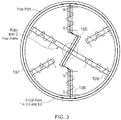
- Fig. 3 shows a typical arrangement for a simple Switched Reluctance (SR) machine. It shows the two inner magnetic paths of the rotor 105 which, when in alignment, complete the flux path for the stator coils 106. In the example shown in Fig. 3 , there are three “coil pairs" denoted by the numbers 1-6. Each pair of coils is positioned opposite each other in the stator 107.
- SR Switched Reluctance
- the SRM can be understood quite simply as a machine driven by magnetic attraction, so a current flow is a created in one of the coil pairs that creates a magnetic field that attracts the nearest rotor element until it pulls it into line. Once this pole pair is aligned the next pair of coils in the required direction of rotation is energized and the rotor moves to the next position and so the process proceeds. For example, from the position shown in Figure 3 energizing coils 1 and 4 would attract the rotor poles and drive the rotor counter-clockwise whilst energizing coils 2 and 5 would attract the rotor in a clockwise direction.
- Fig. 4 shows the electrical equivalent of the SRM in Fig. 3 for counter-clockwise rotation.
- each pair of coils 106 are connected in series between the positive and negative supply lines.
- a pair of switches 109 are used to energise each pair of coils in accordance with the switching phase sequence shown at the top of the Figure.
- a current path when the switches are open and the phase is in freewheeling or generating mode is provided by diodes 108.
- the final problem often cited against the SR generator is the need for complex control and sensor based solutions that inherently reduce the system reliability below acceptable levels for a dedicated power source.
- the generators and methods of operation of the present invention aim to address this problem.
- a first aspect of the present invention provide a method of controlling a switched reluctance generator in a self-commutating fashion.
- the present invention provides a method of controlling a switched reluctance generator according to claim 1 and a switched reluctance generator according to claim 10
- the windings may be on either the stator or rotor poles.
- the windings are on the stator poles as this removes the need to arrange for connections to the windings which are maintained whilst the rotor is rotating.
- the other poles may be permanent magnets, or may have their own windings which are permanently energised when the generator is running.
- the switched reluctance generator has variable rather than fixed flux.
- peak flux need only be applied under transient conditions during very low speed operation or under peak load conditions and this means that the losses in the magnetic circuit can be much lower during normal operation than the fixed flux permanent magnet solutions.
- Variable flux also provides the ability to tap into the extra power of the machine at higher speeds without raising the output voltage.
- the field current is naturally increased during the transit of the opposite pole (for a generator with stator windings, the rotor pole) over the winding (for a generator with stator windings, on the stator pole). This produces positive feedback making the average output current greater than that established by the field excitation.
- the commencement of current flow may then be used as a robust timing indicator for the pole transition.
- this feedback to control the energising of the windings means that the generator can operate without additional complex timing functions or sensor input. It can also improve the efficiency of the generator by potentially ensuring that windings are not energised whilst a winding is delivering power to the load, which would result in higher losses.
- each of said windings may be excited at a time when said windings are not generating current, or are generating current which is below a pre-determined level.
- the excitation may also be controlled to ensure that the peak excitation current never exceeds that which can be usefully used by the machine either by active limiting or by delaying the application of excitation after the cessation of current delivery to the load by a pre-determined period.
- Each winding may be controlled and energised independently of the other windings. When each winding is controlled completely independently, this potentially provides very high integrity by redundancy, as well as potentially providing greater efficiency under normal running conditions than is possible with a PMA. Thus winding independence is important for aerospace applications where a high degree of fault tolerance is required.
- the windings on the poles may also be connected in series pairs or quads to improve performance.
- the generator outputs a multiple phase output to the load and the multiple phases are supplied from different ones of said windings.
- the method includes the steps of: storing the timing of the ceasing of excitation of at least one winding in one cycle; and using said stored timings to determine the timing of exciting one or more of said windings in a subsequent cycle.
- the generator is supplying a multiple phase output
- the steps of storing the timing and using said stored timing may be performed, for each winding, by: storing the timing of the ceasing of excitation of said winding in one cycle; and using said stored timing to determine the timing of exciting said winding in the subsequent cycle.
- the method may further include a step of regulating the power output from the generator by adjusting the timing of exciting said windings compared to the stored timings.
- the method may involve the further step of regulating the output from the generator to the load by adjusting either the amplitude or the timing of the excitation of the windings. This may allow the same self-commutation feature to also be used to modulate the output current. This modulation may be carried out in response to a "demand" input, for example from a controller monitoring the load, or a user.
- the method may include regulating the output such that there is a minimum current flowing through each winding.
- This minimum current flow can set the flux as a function of the average air gap between the rotor and stator whilst the rotor speed sets the EMF
- the method may ensure that the energy consumed in the flux generation process of the generator does not exceed the energy delivered by the generator at any given speed. This may be achieved, for example, by centrally monitoring the output voltage or by averaging the input and output current flows and adjusting the demand to match the available power.
- the switched reluctance generator requires a current flow to energise the windings to generate flux to create a voltage, it is theoretically unable to start generation from an unpowered situation. Although, in real terms, it is nearly impossible to completely de-magnetise the machine so there will normally be some residual flux which can be used in the start up process, the generator may have further provision to enable or guarantee start-up.
- the generator may include small permanent magnets in the flux path which will give sufficient voltage to begin the process of energising the windings.
- the generator may further include an energy storage device and the method may then include the further steps of storing energy whilst the generator is not operational and using said stored energy to energise the windings when the generator is started.
- the small amount of voltage generated either from the residual flux or from the permanent magnets can then be stored to provide enough energy to establish the necessary flux to start the generation process.
- the energy to establish the necessary flux may be provided from an external power source.
- the method of this aspect may include some, all or none of the above described optional features in any combination.
- the method of this aspect may be used in combination with the switched reluctance generator of the second aspect below, it need not be and can be used in conjunction with other switched reluctance generators.
- a second aspect of the present invention provides a switched reluctance generator which is self-commutating.
- the second aspect of the present invention provides a switched reluctance generator according to claim 10.
- the level of excitation delivered to a winding may be determined to match the machine to the load.
- the windings may be on either the stator or rotor poles.
- the windings are on the stator poles as this removes the need to arrange for connections to the windings which are maintained whilst the rotor is rotating.
- the other poles may be permanent magnets, or may have their own windings which are permanently energised when the generator is running.
- the switched reluctance generator has variable rather than fixed flux.
- peak flux need only be applied under transient conditions during very low speed operation or under peak load conditions and this means that the losses in the magnetic circuit can be much lower during normal operation than the fixed flux permanent magnet solutions.
- Variable flux also provides the ability to tap into the extra power of the machine at higher speeds without raising the output voltage.
- the excitation current is naturally increased during the transit of the opposite pole (for a generator with stator windings, the rotor pole) over the winding (for a generator with stator windings, on the stator pole). This produces positive feedback making the average output current greater than that established by the initial excitation set by the controller.
- the commencement of current flow to load may then be used as a robust timing indicator for the pole transition.
- this feedback to control the energising of the windings means that the generator can operate without additional complex timing functions or sensor input. It can also improve the efficiency of the generator by potentially ensuring that windings are not energised whilst a winding is delivering power to the load, which would result in higher losses.
- the controller may be arranged to excite each of said windings at a time when said windings are not generating current, or are generating current which is below a pre-determined level.
- the controller may also be configured to ensure that the peak excitation current never exceeds that which can be usefully used by the machine either by active limiting or by delaying the application of excitation after the cessation of current delivery to the load by a pre-determined period.
- the controller may be arranged to control each winding independently of the other windings. When each winding is controlled completely independently, this potentially provides very high integrity by redundancy, as well as potentially providing greater efficiency under normal running conditions than is possible with a PMA. Thus winding independence is important for aerospace applications where a high degree of fault tolerance is required.
- the windings on the poles may also be connected in series pairs or quads to improve performance.
- the generator outputs a multiple phase output to the load and the controller is arranged to supply said multiple phases from different ones of said windings.
- the control of each phase may be independent and single or multiple phases may drive individual loads connected to the generator.
- the generator may further comprise one or more comparators to determine when the current generated in each winding exceeds said predetermined threshold.
- the controller is arranged to: store the timing of the ceasing of exciting at least one winding in one cycle; and use said stored timings to determine the timing of exciting one or more of said windings in a subsequent cycle.
- the generator is supplying a multiple phase output
- the controller in order to store the timing and to use said stored timing, is arranged to, for each winding: store the timing of exciting said winding in one cycle; and use said stored timing to determine the timing of exciting said winding in the subsequent cycle.
- the controller may be arranged to regulate the power output from the generator by adjusting the timing of exciting said windings compared to the stored timings.
- the controller may be further arranged to regulate the output from the generator to the load by modulating the output current from the windings by adjusting either the amplitude or the timing of the excitation of the windings. This may allow the same self-commutation feature of the controller to also be used to modulate the output current. This modulation may be carried out in response to a "demand" input, for example from a controller monitoring the load, or a user.
- the controller may be arranged to regulate the output such that there is a minimum current flowing through each winding.
- This minimum current flow can set the flux as a function of the average air gap between the rotor and stator whilst the rotor speed sets the electromotive force (EMF).
- the controller may be further arranged to ensure that the energy consumed in the flux generation process of the generator does not exceed the energy delivered by the generator at any given speed. This may be achieved, for example, by centrally monitoring the output voltage or by averaging the input and output current flows and adjusting the demand to match the available power.
- the switched reluctance generator requires a current flow to energise the windings to generate flux to create a voltage, it is theoretically unable to start generation from an unpowered situation. Although, in real terms, it is nearly impossible to completely de-magnetise the machine so there will normally be some residual flux which can be used in the start up process, the generator may have further provision to enable or guarantee start-up.
- the generator may include small permanent magnets in the flux path which will give sufficient voltage to begin the process of energising the windings.
- the generator may further include an energy storage device which is arranged to store energy which is used to energise the windings when the generator is started.
- the small amount of voltage generated either from the residual flux or from the permanent magnets can then be stored to provide enough energy to establish the necessary flux to start the generation process.
- the energy to establish the necessary flux may be provided from an external power source.
- the generator of this aspect is particularly suitable for use in an aerospace setting, for example in accordance with the third aspect described below.
- the generator can be used in many other settings as well.
- the generator of this aspect may include some, all or none of the above described optional features in any combination.
- a third aspect of the present invention provides an engine according to claim 13.
- An embodiment of this aspect provides an aerospace dedicated generator and regulator that is both fault-tolerant and simple. This generator does not rely on complex sensors or microprocessor technology and is therefore more robust and certifiable than systems described in the prior art.
- Switched reluctance generators are known for their ruggedness and ease of construction which make them highly suited to an aerospace application.
- the switched reluctance generator of the above second aspect is even more suited for this application as it can improve on the efficiency and reliability of known switched reluctance generators.
- the switched reluctance generator of the above second aspect can reduce or remove the need for complex control and sensor based solutions to control the operation of the generator.
- Such control and sensor requirements generally reduce the reliability of a switched reluctance generator below the acceptable levels for a dedicated power source in an aerospace application.
- the switched reluctance generator of the above first aspect can achieve a reliability and certifiability which is acceptable for an aerospace application.
- variable flux of the generator can enable high integrity actuation loads needed to improve engine efficiency from a dedicated source.
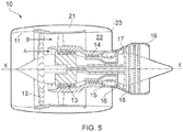
- a ducted fan gas turbine engine according to an embodiment of the present invention is generally indicated at 10 and has a principal and rotational axis X-X.
- the engine comprises, in axial flow series, an air intake 11, a propulsive fan 12, an intermediate pressure compressor 13, a high-pressure compressor 14, combustion equipment 15, a high-pressure turbine 16, an intermediate pressure turbine 17, a low-pressure turbine 18 and a core engine exhaust nozzle 19.
- a nacelle 21 generally surrounds the engine 10 and defines the intake 11, a bypass duct 22 and a bypass exhaust nozzle 23.
- air entering the intake 11 is accelerated by the fan 12 to produce two air flows: a first air flow A into the intermediate pressure compressor 13 and a second air flow B which passes through the bypass duct 22 to provide propulsive thrust.
- the intermediate pressure compressor 13 compresses the air flow A directed into it before delivering that air to the high pressure compressor 14 where further compression takes place.
- the compressed air exhausted from the high-pressure compressor 14 is directed into the combustion equipment 15 where it is mixed with fuel and the mixture combusted.
- the resultant hot combustion products then expand through, and thereby drive the high, intermediate and low-pressure turbines 16, 17, 18 before being exhausted through the nozzle 19 to provide additional propulsive thrust.
- the high, intermediate and low-pressure turbines respectively drive the high and intermediate pressure compressors 14, 13 and the fan 12 by suitable interconnecting shafts.
- gearbox Attached to one of those shafts is an off-take for a gearbox (not shown).
- the gearbox drives various ancillary components, including a dedicated alternator, which may be a generator according to a further embodiment of the present invention, for example as described further below.
- the basic concept is that the machine can be seen as an analogue of the series wound brushed DC generator, elements of which have been in use since the inception of electrical generation.
- the key feature of the series wound brushed DC generator for the purpose of understanding the SRG is that the output current flow occurs in the same direction and in the same magnetic elements needed to increase the magnetic field of the machine in a positive direction.
- the load current on the machine increase so does the ability of the machine to deliver more power, so a positive feedback mechanism is achieved.
- Fig. 6 shows schematically the linkage between the rotor 105 spinning counter-clockwise and the inductance in the coil of winding pole n.
- the inductance of winding n begins to rise and an EMF is generated in winding n that opposes the flow of current in the desired direction.
- the PWM controller would be actively maintaining the desired current flow. This current is maintained as the pole and rotor cross each other and the inductance begins to fall at which point the voltage across the winding reverses polarity and, if a load is present, current begins to flow that causes an increase in flux and power generation as the inductance of pole n again returns to its minimum condition.
- the embodiment shown in Fig. 14 moves towards this final system although final voltage loop closure is not completed. Also the excitation currents in the embodiment shown in Fig. 14 are generated using power FETs operating in linear mode, whereas in practice it may be preferable that the FETs are driven in PWM switch mode (the simpler linear solution appears to be viable, in which case use of the more complex PWM solution may not be necessary).
- the basic idea behind the generators of the embodiments described below is to base a switched reluctance generator regulator on a little used feature of the SRG that it behaves like a series wound DC generator. This means that once a phase is generating the field current is naturally increased during the rotor pole transit over the stator pole winding. This produces positive feedback making the average output current greater than that established by the field excitation and the commencement of current flow can be used as a robust timing indicator for the rotor pole transition.
- Embodiments of the invention can vary but will generally consist of a uni-polar switch mode current drive per phase of the machine. Such a drive might feature one or two active switches but would follow the typical arrangement for an SRM motor drive.
- the phase drives can be linked together by a common demand that will set the minimum current flow in the phase.
- This minimum current flow can set the flux as a function of the average air gap whilst the rotor speed sets the resulting EMF. It is important to ensure that the energy consumed in the flux generation process at no point exceeds the energy delivered by the machine at any given speed. This problem might occur if the output voltage rises to high for the combination of flux and speed to accommodate so current does not flow to output or if the losses in the current drive exceed the power available from the machine.
- Fig. 7 shows a functional block diagram of a very basic phase drive which incorporates a threshold comparator 201 that provides the "self commutation" of the generator. Without this threshold comparator 201, the excitation drive is active whilst the SRG is delivering power and losses are higher than is necessary.
- Fig. 8 shows a schematic circuit diagram of the phase drive of Fig. 7 .
- Fig. 9 shows the results; although the generated phase current is very similar in each case the power lost in the excitation is much higher, peaking at 45W if the "self commutation" feature is not active.
- This basic self commutating design can be refined by further suppressing the delivery of excess current by timing its application relative to the "self commutation". This refinement results in a further reduction in loss power from 660mW to 200mW.
- timing control uses the "self commutation" timing from the previous SRG phase output cycle to predict the optimal point at which to apply the excitation voltage for the next phase power output cycle. If it is used in this manner it simply minimizes the power lost in the drive stage.
- This timing data is generated by capacitors and stored from cycle to cycle on capacitors but it would be possible for this to be in digital form if the reliability of such digital circuits was considered adequate.
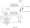
- Fig. 10 shows a functional block diagram for a single phase drive of an SRG according to an embodiment of the present invention in which a predictive timing control 202 is added which works in parallel with the threshold comparator to control the "self commutation" of the generator.
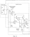
- Fig. 11 shows a schematic circuit diagram of the single phase drive with predictive timing control.
- Fig. 14 shows a SRG according to an embodiment of the present invention having 4 stator poles 306 which have coils attached to separate control devices 307 and 6 rotor poles 305.
- Each phase drive controller X2 to X5 is an instantiation of the design shown in Fig.
- the SRG is created from a set of independent phases with time shifting to represent the relative position of a six position rotor.
- the control devices 307 share a common "Demand" input and a common timing reference ("T_Ref").
- T_Ref common timing reference
- Simulation results for the four phase SRG of Fig. 14 are shown in Fig. 13 , where the predictive timing element is modified by the demand voltage over a range that first improves the power lost to excitation and then reduces the peak output current of the phases, resulting in a controlled reduction in the average current flow in the load Id(M1).
Landscapes
- Engineering & Computer Science (AREA)
- Power Engineering (AREA)
- Control Of Eletrric Generators (AREA)
Claims (13)
- Verfahren zum Steuern eines geschalteten Reluktanzgenerators, wobei der Generator Folgendes beinhaltet:einen Rotor (105, 305), der eine Vielzahl von Rotorpolen aufweist; undeinen Stator, der eine Vielzahl von Statorpolen aufweist, wobei:
entweder die Vielzahl von Rotorpolen oder die Vielzahl von Statorpolen jeweils Wicklungen (106, 306) aufweist, denen Strom zugeführt werden kann, um die Pole zu erregen, und von denen Strom zu einer Last gezogen werden kann, wobei das Verfahren durch die folgenden Schritte gekennzeichnet ist:periodisches Erregen von jeder der Wicklungen nacheinander auf ein vorbestimmtes Stromniveau;Messen des in jeder Wicklung erzeugten Stroms;Unterbrechen der Erregung, wenn der in jeder Wicklung erzeugte Strom den Erregerstrom überschreitet;Leiten des erzeugten Stroms in jeder Wicklung zu der Last;Speichern des Zeitpunktes des Aufhörens der Erregung von zumindest einer Wicklung (106, 306) in einem Zyklus; undVerwenden des gespeicherten Zeitpunktes, um den Zeitpunkt des Erregens von einer oder mehreren der Wicklungen (106, 306) in einem nachfolgenden Zyklus zu bestimmen. - Verfahren nach Anspruch 1, wobei jede der Wicklungen (106, 306) zu einer Zeit erregt wird, zu der die Wicklungen keinen Strom erzeugen oder Strom erzeugen, der unter einem vorbestimmten Niveau liegt.
- Verfahren nach Anspruch 1 oder Anspruch 2, wobei jede Wicklung (106, 306) unabhängig von den anderen Wicklungen erregt wird.
- Verfahren nach einem der vorhergehenden Ansprüche, wobei der Generator eine Mehrphasenausgabe an die Last ausgibt und die Mehrphasen von verschiedenen der Wicklungen (106, 306) zugeführt werden.
- Verfahren nach einem der Ansprüche 1 bis 4, wobei die Schritte des Speicherns des Zeitpunktes und des Verwendens des gespeicherten Zeitpunktes für jede Wicklung (106, 306) durchgeführt werden durch:Speichern des Zeitpunktes des Aufhörens der Erregung der Wicklung (106, 306) in einem Zyklus; undVerwenden des gespeicherten Zeitpunktes, um den Zeitpunkt der Erregung der Wicklung (106, 306) in dem nachfolgenden Zyklus zu bestimmen.
- Verfahren nach einem der vorhergehenden Ansprüche, ferner beinhaltend den Schritt des Regulierens der von dem Generator ausgegebenen Leistung durch Einstellen des Zeitpunktes der Erregung der Wicklungen (106, 306) verglichen mit den gespeicherten Zeitpunkten.
- Verfahren nach einem der vorhergehenden Ansprüche, ferner beinhaltend den folgenden Schritt:
Regulieren der Ausgabe von dem Generator an die Last durch Modulieren des Ausgabestroms von den Wicklungen (106, 306) durch Einstellen entweder der Amplitude oder des Zeitpunktes der Erregung der Wicklungen. - Verfahren nach Anspruch 7, ferner beinhaltend den Schritt des Regulierens der Ausgabe, sodass es einen minimalen Strom gibt, der durch jede Wicklung (106, 306) fließt.
- Verfahren nach einem der vorhergehenden Ansprüche, ferner beinhaltend die folgenden Schritte:Speichern von Energie, während der Generator nicht in Betrieb ist; undVerwenden der gespeicherten Energie, um die Wicklungen (106, 306) zu erregen, wenn der Generator gestartet wird.
- Geschalteter Reluktanzgenerator, wobei der Generator Folgendes beinhaltet:einen Rotor (105, 305), der eine Vielzahl von Rotorpolen aufweist;einen Stator, der eine Vielzahl von Statorpolen aufweist; undeine Steuerung, wobei:
entweder die Vielzahl von Rotorpolen oder die Vielzahl von Statorpolen jeweils Wicklungen (106, 306) aufweist, denen Strom zugeführt werden kann, um die Pole zu erregen, und von denen Strom zu einer Last gezogen werden kann; dadurch gekennzeichnet, dass die Steuerung angeordnet ist, um den Generator zu steuern, indem ein Verfahren nach einem der Ansprüche 1 bis 9 ausgeführt wird. - Generator nach Anspruch 10, ferner umfassend einen oder mehrere Komparatoren (201), um zu bestimmen, wann der in jeder Wicklung erzeugte Strom die vorbestimmte Schwelle überschreitet.
- Generator nach Anspruch 10 oder Anspruch 11, ferner beinhaltend eine Energiespeichervorrichtung, die angeordnet ist, um Energie zu speichern, die verwendet wird, um die Wicklungen (106, 306) zu erregen, wenn der Generator gestartet wird.
- Triebwerk (10), das einen dedizierten Generator aufweist, der ein geschalteter Reluktanzgenerator nach einem der Ansprüche 10 bis 12 ist.
Applications Claiming Priority (2)
| Application Number | Priority Date | Filing Date | Title |
|---|---|---|---|
| GBGB1500499.7A GB201500499D0 (en) | 2015-01-13 | 2015-01-13 | Generator and method for controlling a generator |
| PCT/GB2016/050072 WO2016113558A1 (en) | 2015-01-13 | 2016-01-13 | Generator and method for controlling a generator |
Publications (2)
| Publication Number | Publication Date |
|---|---|
| EP3245729A1 EP3245729A1 (de) | 2017-11-22 |
| EP3245729B1 true EP3245729B1 (de) | 2021-03-24 |
Family
ID=52597524
Family Applications (1)
| Application Number | Title | Priority Date | Filing Date |
|---|---|---|---|
| EP16701366.3A Active EP3245729B1 (de) | 2015-01-13 | 2016-01-13 | Generator und verfahren zur steuerung eines generators |
Country Status (4)
| Country | Link |
|---|---|
| US (1) | US10516357B2 (de) |
| EP (1) | EP3245729B1 (de) |
| GB (1) | GB201500499D0 (de) |
| WO (1) | WO2016113558A1 (de) |
Families Citing this family (4)
| Publication number | Priority date | Publication date | Assignee | Title |
|---|---|---|---|---|
| CN108667383B (zh) * | 2018-06-06 | 2019-11-15 | 中国计量大学 | 一种小型开关磁阻电机变流器系统 |
| CN111262607B (zh) * | 2020-01-17 | 2021-05-28 | 中国矿业大学 | 一种适用于srg直流微网电力线数据通信的数据调制方法 |
| US11699966B1 (en) | 2022-02-11 | 2023-07-11 | Hamilton Sundstrand Corporation | Open flyback diode protection |
| CN116111891B (zh) * | 2023-04-17 | 2023-07-28 | 国网天津市电力公司电力科学研究院 | 同步调相机调速方法、调速装置、电子设备、存储介质 |
Family Cites Families (12)
| Publication number | Priority date | Publication date | Assignee | Title |
|---|---|---|---|---|
| US4625160A (en) * | 1984-12-17 | 1986-11-25 | Sundstrand Corporation | Variable speed constant frequency generating system |
| US4965463A (en) * | 1987-06-15 | 1990-10-23 | Sanyo Denki Co., Ltd. | Flat frequency, constant voltage power source device |
| US5404091A (en) * | 1993-05-27 | 1995-04-04 | General Electric Company | Switched reluctance generator system with self-excitation capability during load faults |
| US5936386A (en) * | 1997-09-10 | 1999-08-10 | Sundstrand Corporation | Method of linearizing the performance of switched reluctance generators |
| GB9928843D0 (en) * | 1999-12-06 | 2000-02-02 | Lucas Industries Ltd | Switched reluctance generator and a method of controlling such a generator |
| GB9929655D0 (en) | 1999-12-15 | 2000-02-09 | Switched Reluctance Drives Ltd | Rotor position monitoring of a switched reluctance drive |
| US6661206B2 (en) | 2001-12-10 | 2003-12-09 | Delphi Technologies, Inc. | Soft chopping for switched reluctance generators |
| JP3668938B2 (ja) * | 2001-12-11 | 2005-07-06 | 三菱電機株式会社 | 回転電機 |
| US7071659B1 (en) * | 2004-01-23 | 2006-07-04 | Dana Corporation | Closed loop control of excitation parameters for high speed switched-reluctance generators |
| KR100704482B1 (ko) * | 2005-04-01 | 2007-04-09 | 엘지전자 주식회사 | 저속 영역과 고속 영역에서의 발전 효율이 개선된 에스알발전기 |
| US7638985B2 (en) | 2006-08-17 | 2009-12-29 | Hamilton Sundstrand Corporation | Self-excitation of switched reluctance generators during load bus faults |
| CN102904515B (zh) | 2012-10-22 | 2015-03-04 | 中国矿业大学 | 开关磁阻发电机无位置传感器控制方法 |
-
2015
- 2015-01-13 GB GBGB1500499.7A patent/GB201500499D0/en not_active Ceased
-
2016
- 2016-01-13 WO PCT/GB2016/050072 patent/WO2016113558A1/en not_active Ceased
- 2016-01-13 EP EP16701366.3A patent/EP3245729B1/de active Active
- 2016-01-13 US US15/543,195 patent/US10516357B2/en active Active
Non-Patent Citations (1)
| Title |
|---|
| None * |
Also Published As
| Publication number | Publication date |
|---|---|
| EP3245729A1 (de) | 2017-11-22 |
| WO2016113558A1 (en) | 2016-07-21 |
| GB201500499D0 (en) | 2015-02-25 |
| US20170373624A1 (en) | 2017-12-28 |
| US10516357B2 (en) | 2019-12-24 |
Similar Documents
| Publication | Publication Date | Title |
|---|---|---|
| US8796871B2 (en) | Turbine engine starter/generator, and method for the control thereof | |
| US10378445B2 (en) | Gas turbine engine fuel system | |
| CN100423440C (zh) | 使用多相电力发电机来启动燃气涡轮的方法及设备 | |
| EP3012438B1 (de) | Gasturbinentriebwerkskraftstoffsystem | |
| EP1903212A2 (de) | Mit mehreren variablen Spannungen und Frequenzen betreibbarer Startergenerator | |
| JP5026243B2 (ja) | 発電機および発電機によって生成される交流の周波数を制御する方法 | |
| JP5216686B2 (ja) | 永久磁石形発電機 | |
| US9573539B2 (en) | Electric system architecture for more-electric engine accessories | |
| JP2013509525A5 (de) | ||
| US10516357B2 (en) | Generator and method for controlling a generator | |
| JP5449831B2 (ja) | 可変速度発電機を始動させることに関連するシステム及び方法 | |
| US9166510B1 (en) | Systems utilizing a controllable voltage AC generator system | |
| EP1236269A1 (de) | Geschalteter reluktanzgenerator und methode zu seiner ansteuerung | |
| JP6334291B2 (ja) | 交流励磁機の励磁装置 | |
| EP4195493A1 (de) | Parallele anregung der motorstartfunktion für einen dreistufigen synchrongenerator | |
| US10797574B2 (en) | Electrical machine | |
| EP3023331A1 (de) | Luftfahrzeugantrieb und verfahren zur erzeugung elektrischer energie für ein luftfahrzeugversorgungssystem | |
| US11527975B2 (en) | Low-power bias supply to facilitate the low-RPM startup of three-phase AC aircraft generators | |
| US12428998B2 (en) | Aircraft engine start using multiple common motor controllers | |
| RU66635U1 (ru) | Асинхронизированный синхронный генератор | |
| PL221325B1 (pl) | Układ połączenia generatora synchronicznego wzbudzanego magnesami trwałymi do pracy równoległej z siecią elektroenergetyczną |
Legal Events
| Date | Code | Title | Description |
|---|---|---|---|
| STAA | Information on the status of an ep patent application or granted ep patent |
Free format text: STATUS: THE INTERNATIONAL PUBLICATION HAS BEEN MADE |
|
| PUAI | Public reference made under article 153(3) epc to a published international application that has entered the european phase |
Free format text: ORIGINAL CODE: 0009012 |
|
| STAA | Information on the status of an ep patent application or granted ep patent |
Free format text: STATUS: REQUEST FOR EXAMINATION WAS MADE |
|
| 17P | Request for examination filed |
Effective date: 20170804 |
|
| AK | Designated contracting states |
Kind code of ref document: A1 Designated state(s): AL AT BE BG CH CY CZ DE DK EE ES FI FR GB GR HR HU IE IS IT LI LT LU LV MC MK MT NL NO PL PT RO RS SE SI SK SM TR |
|
| AX | Request for extension of the european patent |
Extension state: BA ME |
|
| DAV | Request for validation of the european patent (deleted) | ||
| DAX | Request for extension of the european patent (deleted) | ||
| STAA | Information on the status of an ep patent application or granted ep patent |
Free format text: STATUS: EXAMINATION IS IN PROGRESS |
|
| 17Q | First examination report despatched |
Effective date: 20190621 |
|
| RAP1 | Party data changed (applicant data changed or rights of an application transferred) |
Owner name: ROLLS-ROYCE PLC |
|
| GRAP | Despatch of communication of intention to grant a patent |
Free format text: ORIGINAL CODE: EPIDOSNIGR1 |
|
| STAA | Information on the status of an ep patent application or granted ep patent |
Free format text: STATUS: GRANT OF PATENT IS INTENDED |
|
| GRAS | Grant fee paid |
Free format text: ORIGINAL CODE: EPIDOSNIGR3 |
|
| INTG | Intention to grant announced |
Effective date: 20210122 |
|
| GRAA | (expected) grant |
Free format text: ORIGINAL CODE: 0009210 |
|
| STAA | Information on the status of an ep patent application or granted ep patent |
Free format text: STATUS: THE PATENT HAS BEEN GRANTED |
|
| AK | Designated contracting states |
Kind code of ref document: B1 Designated state(s): AL AT BE BG CH CY CZ DE DK EE ES FI FR GB GR HR HU IE IS IT LI LT LU LV MC MK MT NL NO PL PT RO RS SE SI SK SM TR |
|
| REG | Reference to a national code |
Ref country code: GB Ref legal event code: FG4D |
|
| REG | Reference to a national code |
Ref country code: CH Ref legal event code: EP |
|
| REG | Reference to a national code |
Ref country code: IE Ref legal event code: FG4D |
|
| REG | Reference to a national code |
Ref country code: AT Ref legal event code: REF Ref document number: 1375531 Country of ref document: AT Kind code of ref document: T Effective date: 20210415 Ref country code: DE Ref legal event code: R096 Ref document number: 602016054756 Country of ref document: DE |
|
| REG | Reference to a national code |
Ref country code: LT Ref legal event code: MG9D |
|
| PG25 | Lapsed in a contracting state [announced via postgrant information from national office to epo] |
Ref country code: GR Free format text: LAPSE BECAUSE OF FAILURE TO SUBMIT A TRANSLATION OF THE DESCRIPTION OR TO PAY THE FEE WITHIN THE PRESCRIBED TIME-LIMIT Effective date: 20210625 Ref country code: HR Free format text: LAPSE BECAUSE OF FAILURE TO SUBMIT A TRANSLATION OF THE DESCRIPTION OR TO PAY THE FEE WITHIN THE PRESCRIBED TIME-LIMIT Effective date: 20210324 Ref country code: FI Free format text: LAPSE BECAUSE OF FAILURE TO SUBMIT A TRANSLATION OF THE DESCRIPTION OR TO PAY THE FEE WITHIN THE PRESCRIBED TIME-LIMIT Effective date: 20210324 Ref country code: NO Free format text: LAPSE BECAUSE OF FAILURE TO SUBMIT A TRANSLATION OF THE DESCRIPTION OR TO PAY THE FEE WITHIN THE PRESCRIBED TIME-LIMIT Effective date: 20210624 Ref country code: BG Free format text: LAPSE BECAUSE OF FAILURE TO SUBMIT A TRANSLATION OF THE DESCRIPTION OR TO PAY THE FEE WITHIN THE PRESCRIBED TIME-LIMIT Effective date: 20210624 |
|
| PG25 | Lapsed in a contracting state [announced via postgrant information from national office to epo] |
Ref country code: SE Free format text: LAPSE BECAUSE OF FAILURE TO SUBMIT A TRANSLATION OF THE DESCRIPTION OR TO PAY THE FEE WITHIN THE PRESCRIBED TIME-LIMIT Effective date: 20210324 Ref country code: RS Free format text: LAPSE BECAUSE OF FAILURE TO SUBMIT A TRANSLATION OF THE DESCRIPTION OR TO PAY THE FEE WITHIN THE PRESCRIBED TIME-LIMIT Effective date: 20210324 Ref country code: LV Free format text: LAPSE BECAUSE OF FAILURE TO SUBMIT A TRANSLATION OF THE DESCRIPTION OR TO PAY THE FEE WITHIN THE PRESCRIBED TIME-LIMIT Effective date: 20210324 |
|
| REG | Reference to a national code |
Ref country code: NL Ref legal event code: MP Effective date: 20210324 |
|
| REG | Reference to a national code |
Ref country code: AT Ref legal event code: MK05 Ref document number: 1375531 Country of ref document: AT Kind code of ref document: T Effective date: 20210324 |
|
| PG25 | Lapsed in a contracting state [announced via postgrant information from national office to epo] |
Ref country code: NL Free format text: LAPSE BECAUSE OF FAILURE TO SUBMIT A TRANSLATION OF THE DESCRIPTION OR TO PAY THE FEE WITHIN THE PRESCRIBED TIME-LIMIT Effective date: 20210324 |
|
| PG25 | Lapsed in a contracting state [announced via postgrant information from national office to epo] |
Ref country code: SM Free format text: LAPSE BECAUSE OF FAILURE TO SUBMIT A TRANSLATION OF THE DESCRIPTION OR TO PAY THE FEE WITHIN THE PRESCRIBED TIME-LIMIT Effective date: 20210324 Ref country code: AT Free format text: LAPSE BECAUSE OF FAILURE TO SUBMIT A TRANSLATION OF THE DESCRIPTION OR TO PAY THE FEE WITHIN THE PRESCRIBED TIME-LIMIT Effective date: 20210324 Ref country code: LT Free format text: LAPSE BECAUSE OF FAILURE TO SUBMIT A TRANSLATION OF THE DESCRIPTION OR TO PAY THE FEE WITHIN THE PRESCRIBED TIME-LIMIT Effective date: 20210324 Ref country code: CZ Free format text: LAPSE BECAUSE OF FAILURE TO SUBMIT A TRANSLATION OF THE DESCRIPTION OR TO PAY THE FEE WITHIN THE PRESCRIBED TIME-LIMIT Effective date: 20210324 Ref country code: EE Free format text: LAPSE BECAUSE OF FAILURE TO SUBMIT A TRANSLATION OF THE DESCRIPTION OR TO PAY THE FEE WITHIN THE PRESCRIBED TIME-LIMIT Effective date: 20210324 |
|
| PG25 | Lapsed in a contracting state [announced via postgrant information from national office to epo] |
Ref country code: IS Free format text: LAPSE BECAUSE OF FAILURE TO SUBMIT A TRANSLATION OF THE DESCRIPTION OR TO PAY THE FEE WITHIN THE PRESCRIBED TIME-LIMIT Effective date: 20210724 Ref country code: PT Free format text: LAPSE BECAUSE OF FAILURE TO SUBMIT A TRANSLATION OF THE DESCRIPTION OR TO PAY THE FEE WITHIN THE PRESCRIBED TIME-LIMIT Effective date: 20210726 Ref country code: PL Free format text: LAPSE BECAUSE OF FAILURE TO SUBMIT A TRANSLATION OF THE DESCRIPTION OR TO PAY THE FEE WITHIN THE PRESCRIBED TIME-LIMIT Effective date: 20210324 Ref country code: SK Free format text: LAPSE BECAUSE OF FAILURE TO SUBMIT A TRANSLATION OF THE DESCRIPTION OR TO PAY THE FEE WITHIN THE PRESCRIBED TIME-LIMIT Effective date: 20210324 Ref country code: RO Free format text: LAPSE BECAUSE OF FAILURE TO SUBMIT A TRANSLATION OF THE DESCRIPTION OR TO PAY THE FEE WITHIN THE PRESCRIBED TIME-LIMIT Effective date: 20210324 |
|
| REG | Reference to a national code |
Ref country code: DE Ref legal event code: R097 Ref document number: 602016054756 Country of ref document: DE |
|
| PG25 | Lapsed in a contracting state [announced via postgrant information from national office to epo] |
Ref country code: AL Free format text: LAPSE BECAUSE OF FAILURE TO SUBMIT A TRANSLATION OF THE DESCRIPTION OR TO PAY THE FEE WITHIN THE PRESCRIBED TIME-LIMIT Effective date: 20210324 Ref country code: ES Free format text: LAPSE BECAUSE OF FAILURE TO SUBMIT A TRANSLATION OF THE DESCRIPTION OR TO PAY THE FEE WITHIN THE PRESCRIBED TIME-LIMIT Effective date: 20210324 Ref country code: DK Free format text: LAPSE BECAUSE OF FAILURE TO SUBMIT A TRANSLATION OF THE DESCRIPTION OR TO PAY THE FEE WITHIN THE PRESCRIBED TIME-LIMIT Effective date: 20210324 |
|
| PLBE | No opposition filed within time limit |
Free format text: ORIGINAL CODE: 0009261 |
|
| STAA | Information on the status of an ep patent application or granted ep patent |
Free format text: STATUS: NO OPPOSITION FILED WITHIN TIME LIMIT |
|
| PG25 | Lapsed in a contracting state [announced via postgrant information from national office to epo] |
Ref country code: SI Free format text: LAPSE BECAUSE OF FAILURE TO SUBMIT A TRANSLATION OF THE DESCRIPTION OR TO PAY THE FEE WITHIN THE PRESCRIBED TIME-LIMIT Effective date: 20210324 |
|
| 26N | No opposition filed |
Effective date: 20220104 |
|
| PG25 | Lapsed in a contracting state [announced via postgrant information from national office to epo] |
Ref country code: IS Free format text: LAPSE BECAUSE OF FAILURE TO SUBMIT A TRANSLATION OF THE DESCRIPTION OR TO PAY THE FEE WITHIN THE PRESCRIBED TIME-LIMIT Effective date: 20210724 |
|
| PG25 | Lapsed in a contracting state [announced via postgrant information from national office to epo] |
Ref country code: MC Free format text: LAPSE BECAUSE OF FAILURE TO SUBMIT A TRANSLATION OF THE DESCRIPTION OR TO PAY THE FEE WITHIN THE PRESCRIBED TIME-LIMIT Effective date: 20210324 |
|
| REG | Reference to a national code |
Ref country code: CH Ref legal event code: PL |
|
| REG | Reference to a national code |
Ref country code: BE Ref legal event code: MM Effective date: 20220131 |
|
| PG25 | Lapsed in a contracting state [announced via postgrant information from national office to epo] |
Ref country code: LU Free format text: LAPSE BECAUSE OF NON-PAYMENT OF DUE FEES Effective date: 20220113 |
|
| PG25 | Lapsed in a contracting state [announced via postgrant information from national office to epo] |
Ref country code: BE Free format text: LAPSE BECAUSE OF NON-PAYMENT OF DUE FEES Effective date: 20220131 |
|
| PG25 | Lapsed in a contracting state [announced via postgrant information from national office to epo] |
Ref country code: LI Free format text: LAPSE BECAUSE OF NON-PAYMENT OF DUE FEES Effective date: 20220131 Ref country code: CH Free format text: LAPSE BECAUSE OF NON-PAYMENT OF DUE FEES Effective date: 20220131 |
|
| PG25 | Lapsed in a contracting state [announced via postgrant information from national office to epo] |
Ref country code: IT Free format text: LAPSE BECAUSE OF FAILURE TO SUBMIT A TRANSLATION OF THE DESCRIPTION OR TO PAY THE FEE WITHIN THE PRESCRIBED TIME-LIMIT Effective date: 20210324 Ref country code: IE Free format text: LAPSE BECAUSE OF NON-PAYMENT OF DUE FEES Effective date: 20220113 |
|
| P01 | Opt-out of the competence of the unified patent court (upc) registered |
Effective date: 20230528 |
|
| PG25 | Lapsed in a contracting state [announced via postgrant information from national office to epo] |
Ref country code: HU Free format text: LAPSE BECAUSE OF FAILURE TO SUBMIT A TRANSLATION OF THE DESCRIPTION OR TO PAY THE FEE WITHIN THE PRESCRIBED TIME-LIMIT; INVALID AB INITIO Effective date: 20160113 |
|
| PG25 | Lapsed in a contracting state [announced via postgrant information from national office to epo] |
Ref country code: MK Free format text: LAPSE BECAUSE OF FAILURE TO SUBMIT A TRANSLATION OF THE DESCRIPTION OR TO PAY THE FEE WITHIN THE PRESCRIBED TIME-LIMIT Effective date: 20210324 Ref country code: CY Free format text: LAPSE BECAUSE OF FAILURE TO SUBMIT A TRANSLATION OF THE DESCRIPTION OR TO PAY THE FEE WITHIN THE PRESCRIBED TIME-LIMIT Effective date: 20210324 |
|
| PG25 | Lapsed in a contracting state [announced via postgrant information from national office to epo] |
Ref country code: MT Free format text: LAPSE BECAUSE OF FAILURE TO SUBMIT A TRANSLATION OF THE DESCRIPTION OR TO PAY THE FEE WITHIN THE PRESCRIBED TIME-LIMIT Effective date: 20210324 |
|
| PG25 | Lapsed in a contracting state [announced via postgrant information from national office to epo] |
Ref country code: TR Free format text: LAPSE BECAUSE OF FAILURE TO SUBMIT A TRANSLATION OF THE DESCRIPTION OR TO PAY THE FEE WITHIN THE PRESCRIBED TIME-LIMIT Effective date: 20210324 |
|
| PGFP | Annual fee paid to national office [announced via postgrant information from national office to epo] |
Ref country code: GB Payment date: 20260126 Year of fee payment: 11 |
|
| PGFP | Annual fee paid to national office [announced via postgrant information from national office to epo] |
Ref country code: DE Payment date: 20260127 Year of fee payment: 11 |
|
| PGFP | Annual fee paid to national office [announced via postgrant information from national office to epo] |
Ref country code: FR Payment date: 20260126 Year of fee payment: 11 |