EP3246074A1 - Machine multifonctionnelle d'entraînement de jambe - Google Patents
Machine multifonctionnelle d'entraînement de jambe Download PDFInfo
- Publication number
- EP3246074A1 EP3246074A1 EP16170531.4A EP16170531A EP3246074A1 EP 3246074 A1 EP3246074 A1 EP 3246074A1 EP 16170531 A EP16170531 A EP 16170531A EP 3246074 A1 EP3246074 A1 EP 3246074A1
- Authority
- EP
- European Patent Office
- Prior art keywords
- framework
- sliding
- device set
- training machine
- leg training
- Prior art date
- Legal status (The legal status is an assumption and is not a legal conclusion. Google has not performed a legal analysis and makes no representation as to the accuracy of the status listed.)
- Granted
Links
Images








Classifications
-
- A—HUMAN NECESSITIES
- A63—SPORTS; GAMES; AMUSEMENTS
- A63B—APPARATUS FOR PHYSICAL TRAINING, GYMNASTICS, SWIMMING, CLIMBING, OR FENCING; BALL GAMES; TRAINING EQUIPMENT
- A63B21/00—Exercising apparatus for developing or strengthening the muscles or joints of the body by working against a counterforce, with or without measuring devices
- A63B21/40—Interfaces with the user related to strength training; Details thereof
- A63B21/4027—Specific exercise interfaces
- A63B21/4033—Handles, pedals, bars or platforms
-
- A—HUMAN NECESSITIES
- A63—SPORTS; GAMES; AMUSEMENTS
- A63B—APPARATUS FOR PHYSICAL TRAINING, GYMNASTICS, SWIMMING, CLIMBING, OR FENCING; BALL GAMES; TRAINING EQUIPMENT
- A63B21/00—Exercising apparatus for developing or strengthening the muscles or joints of the body by working against a counterforce, with or without measuring devices
- A63B21/06—User-manipulated weights
- A63B21/062—User-manipulated weights including guide for vertical or non-vertical weights or array of weights to move against gravity forces
- A63B21/0626—User-manipulated weights including guide for vertical or non-vertical weights or array of weights to move against gravity forces with substantially vertical guiding means
-
- A—HUMAN NECESSITIES
- A63—SPORTS; GAMES; AMUSEMENTS
- A63B—APPARATUS FOR PHYSICAL TRAINING, GYMNASTICS, SWIMMING, CLIMBING, OR FENCING; BALL GAMES; TRAINING EQUIPMENT
- A63B21/00—Exercising apparatus for developing or strengthening the muscles or joints of the body by working against a counterforce, with or without measuring devices
- A63B21/40—Interfaces with the user related to strength training; Details thereof
- A63B21/4041—Interfaces with the user related to strength training; Details thereof characterised by the movements of the interface
- A63B21/4045—Reciprocating movement along, in or on a guide
-
- A—HUMAN NECESSITIES
- A63—SPORTS; GAMES; AMUSEMENTS
- A63B—APPARATUS FOR PHYSICAL TRAINING, GYMNASTICS, SWIMMING, CLIMBING, OR FENCING; BALL GAMES; TRAINING EQUIPMENT
- A63B23/00—Exercising apparatus specially adapted for particular parts of the body
- A63B23/035—Exercising apparatus specially adapted for particular parts of the body for limbs, i.e. upper or lower limbs, e.g. simultaneously
- A63B23/04—Exercising apparatus specially adapted for particular parts of the body for limbs, i.e. upper or lower limbs, e.g. simultaneously for lower limbs
- A63B23/0405—Exercising apparatus specially adapted for particular parts of the body for limbs, i.e. upper or lower limbs, e.g. simultaneously for lower limbs involving a bending of the knee and hip joints simultaneously
-
- A—HUMAN NECESSITIES
- A63—SPORTS; GAMES; AMUSEMENTS
- A63B—APPARATUS FOR PHYSICAL TRAINING, GYMNASTICS, SWIMMING, CLIMBING, OR FENCING; BALL GAMES; TRAINING EQUIPMENT
- A63B23/00—Exercising apparatus specially adapted for particular parts of the body
- A63B23/035—Exercising apparatus specially adapted for particular parts of the body for limbs, i.e. upper or lower limbs, e.g. simultaneously
- A63B23/04—Exercising apparatus specially adapted for particular parts of the body for limbs, i.e. upper or lower limbs, e.g. simultaneously for lower limbs
- A63B23/0405—Exercising apparatus specially adapted for particular parts of the body for limbs, i.e. upper or lower limbs, e.g. simultaneously for lower limbs involving a bending of the knee and hip joints simultaneously
- A63B2023/0411—Squatting exercises
-
- A—HUMAN NECESSITIES
- A63—SPORTS; GAMES; AMUSEMENTS
- A63B—APPARATUS FOR PHYSICAL TRAINING, GYMNASTICS, SWIMMING, CLIMBING, OR FENCING; BALL GAMES; TRAINING EQUIPMENT
- A63B21/00—Exercising apparatus for developing or strengthening the muscles or joints of the body by working against a counterforce, with or without measuring devices
- A63B21/06—User-manipulated weights
- A63B21/078—Devices for bench press exercises, e.g. supports, guiding means
-
- A—HUMAN NECESSITIES
- A63—SPORTS; GAMES; AMUSEMENTS
- A63B—APPARATUS FOR PHYSICAL TRAINING, GYMNASTICS, SWIMMING, CLIMBING, OR FENCING; BALL GAMES; TRAINING EQUIPMENT
- A63B21/00—Exercising apparatus for developing or strengthening the muscles or joints of the body by working against a counterforce, with or without measuring devices
- A63B21/06—User-manipulated weights
- A63B21/078—Devices for bench press exercises, e.g. supports, guiding means
- A63B21/0783—Safety features for bar-bells, e.g. drop limiting means
-
- A—HUMAN NECESSITIES
- A63—SPORTS; GAMES; AMUSEMENTS
- A63B—APPARATUS FOR PHYSICAL TRAINING, GYMNASTICS, SWIMMING, CLIMBING, OR FENCING; BALL GAMES; TRAINING EQUIPMENT
- A63B21/00—Exercising apparatus for developing or strengthening the muscles or joints of the body by working against a counterforce, with or without measuring devices
- A63B21/40—Interfaces with the user related to strength training; Details thereof
- A63B21/4027—Specific exercise interfaces
- A63B21/4033—Handles, pedals, bars or platforms
- A63B21/4035—Handles, pedals, bars or platforms for operation by hand
Definitions
- the present invention relates to exerciser technology and more particularly, to a multifunctional leg training machine.
- a typical leg exercise such as squat, is normally trained using a weightlifting rack, however, it should be very careful when using a weightlifting rack to do a lunge or calf-raise exercise.
- the barbell In early weight training, the barbell is directly carried on the shoulders. This method can simply do the conventional parallel squat exercise to train the muscles of the legs. However, because there is no any safety facilities used in the training, the user can be crushed by the barbell if the user is unable to withstand the load, or a poor training posture can lead to injuries of the waist, spine or knees.
- a Smith machine generally comprises two vertical bars arranged at two opposite lateral sides of a framework in a parallel manner, two sliding sleeves respectively slidably coupled to the vertical bars, and a barbell fixedly connected between the sliding sleeves for vertical movement without vibration.
- this kind of weightlifting training machine can simply allow the user to lift weight vertically such as shoulder press or squat.
- the user can simply move the body up and down. This motion is not a natural arc movement and it will increase knee stress. Further, the user cannot fully train different muscle groups of the legs.
- the present invention has been accomplished under the circumstances in view. It is the main object of the present invention to provide a multifunctional leg training machine, which has a weight-bearing mechanism mounted at the framework thereof and movable in direction toward or away from the framework to impart a downward pressure to the shoulders of the user using the machine, allowing to the user to perform a squat exercise, a lunge exercise, a calf-raise exercise, a simple transverse body movement exercise, or a mixed training exercise of moving the body transversely and vertically to fully train different muscle groups of the legs.
- a multifunctional leg training machine of the invention comprises a framework placed on a bearing surface, and a weight-bearing mechanism mounted in the framework and movable relative to the framework in direction toward or away from the framework.
- the weight-bearing mechanism comprises a longitudinal sliding device set vertically mounted in the framework and movable between the opposing top and bottom sides of the framework, a transverse sliding device set slidably coupled to the longitudinal sliding device set and movable between the opposing left and right sides of the framework, and a plurality of weight plates selectively mountable at the longitudinal sliding device set to impart a downward pressure to the longitudinal sliding device set so that when a user carries the weight-bearing mechanism with the shoulders, the weight plates give a downward pressure to the user.
- the longitudinal sliding device set comprises two vertical bars respectively vertically affixed to the opposing left and right sides of the framework, two sliding sleeves respectively sleeved onto the vertical bars and respectively axially movable along the vertical bars, and a sliding bar connected between the two sliding sleeves for allowing the transverse sliding device set to slide thereon.
- the longitudinal sliding device set comprises two pairs of vertical bars, two sliding sleeve sets, and a sliding bar connected between the sliding sleeve sets.
- the vertical bars are symmetrically fixedly mounted at the opposing left and right sides of the framework.
- the sliding sleeve sets are respectively coupled to and axially movable along the vertical bars.
- the sliding bar has two opposite ends thereof respectively fixedly connected to the sliding sleeve sets for allowing the transverse sliding device set to slide thereon.
- each sliding sleeve set comprises a link and two sliding sleeves.
- the sliding sleeves are respectively fixedly connected to two opposite ends of the link and respectively slidably sleeved onto the respective vertical bars.
- the sliding bar has two opposite ends thereof respectively fixedly connected to the links of the two sliding sleeve sets.
- the longitudinal sliding device set further comprises two stretcher bars respectively and fixedly connected between the links of the two sliding sleeve sets at two opposite sides relative to the sliding bar.
- the longitudinal sliding device set further comprises a hanging rod connected to each sliding sleeve and extending toward the sliding bar for hanging the weight plates.
- the transverse sliding device set comprises a pulley holder frame, a plurality of pulleys, a cushion set and two grips.
- the pulleys are rotatably mounted in the pulley holder frame at two opposite sides relative to the sliding bar.
- the cushion set is fixedly mounted at the pulley holder frame for stopping at the shoulders of the user operating the multifunctional leg training machine.
- the grips are affixed to the pulley holder frame corresponding to the user's shoulders for holding by the user.
- the sliding bar is a rhombic tube having four slanted sides. Each two adjacent slanted sides are connected together to create a sliding rail. Further, each pulley defines therein a sliding groove fitting the sliding rail.
- the cushion set comprises two pivot members and a cushion member.
- the pivot members are fixedly connected to a bottom side of the pulley holder frame.
- the cushion member is pivotally coupled between the two pivot members.
- the multifunctional leg training machine further comprises two positioning mechanisms respectively mounted at the sliding bar of the longitudinal sliding device set near the framework for positioning the weight-bearing mechanism in the framework at a predetermined elevation.
- the framework comprises two upright posts disposed at the opposing left and right sides of the framework and vertically upwardly extended from the bottom side of the framework, and a plurality of positioning rods located at each upright post at different elevations.
- Each positioning mechanism comprises a connection member, a handle and a hook member.
- the connection member is fixedly connected to the sliding bar.
- the handle is pivotally connected to the connection member.
- the hook member is biasable by the handle in two reversed directions to hook on the positioning rod or to release the positioning rod.
- the hook members of the two positioning mechanisms are connected together by a link for enabling the two positioning mechanisms to be moved synchronously.
- the multifunctional leg training machine further comprises two buffering mechanisms.
- Each buffering mechanism comprises a buffer sleeve, a grip and a clamping hook.
- the buffer sleeve is axially slidably and rotatably sleeved onto one respective vertical bar.
- the grip of each buffering mechanism is fixedly connected to the buffer sleeve.
- the clamping hook is biasable by the grip of the respective buffering mechanism in two reversed directions to hook on the positioning rod or to release the positioning rod.
- the framework further comprises two support posts disposed at the opposing left and right sides thereof and upwardly extended from the bottom side thereof, and a plurality of hanging rods located at each support post at different elevations for holding the weight plates that are not in use, facilitating the user to pick up and to store the weight plates.
- the multifunctional leg training machine allows the user to conduct vertical exercises in a squat, lunge or calf-raise posture, or to conduct mixed transverse and vertical training exercises to fully train different muscle groups of the legs.
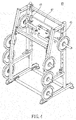
- the multifunctional leg training machine 10 comprises a framework 20, a weight-bearing mechanism 30, two positioning mechanisms 40, and two buffering mechanisms 50.
- the framework 20 is placed on a bearing surface (floor), comprising two upright posts 21 and two support posts 23 located at two opposite lateral sides thereof and upwardly extended from the floor.
- the upright posts 21 are bilaterally disposed at a front side
- the support ports 23 are bilaterally disposed at an opposing rear side.
- the framework 20 further comprises a row of positioning rods 211 located at each upright post 21 at an inner side and spaced along the length thereof at a predetermined interval, and a row of hanging rods 231 located at each support post 23 at an outer side and spaced along the length thereof at a predetermined interval for hanging weight plates (iron discs) 35.
- the number and locations of the positioning rods 211 and the hanging rods 231 shown in the drawings are for the purpose of illustration only but not intended for use to limit the scope of the invention.
- the positioning rods 211 or the hanging rods 231 can be located at only one upright post 21 or one support post 23.
- the weight-bearing mechanism 30 is mounted at the framework 20, and can be moved toward or away from the framework 20.
- the weight-bearing mechanism 30 can provide a weight so that when the user carries the weight-bearing mechanism 30 with the shoulders, the gravity of weight of the weight-bearing mechanism 30 is downwardly applied to the user.
- the weight-bearing mechanism 30 comprises a longitudinal sliding device set 31, a transverse sliding device set 33, and the aforesaid weight plates 35.
- the longitudinal sliding device set 31 is vertically mounted in the framework 20, and can be moved relative to the framework 20 between opposing top and bottom sides of the framework 20.
- the transverse sliding device set 33 is slidably coupled to the longitudinal sliding device set 31, and can be moved relative to the framework 20 between the two opposite lateral sides (the opposing left and right sides) of the framework 20.
- the user can selectively attach a predetermined number of the weight plates 35 to two opposite sides of the longitudinal sliding device set 31 to give a downward pressure.
- the weight plates 35 that are not selected can be hung on the hanging rods 231 of the support posts 23.
- the longitudinal sliding device set 31 comprises two vertical bars 311, two sliding sleeves 313, a sliding bar 315 connected between the sliding sleeves 313, and two hanging rods 317.
- the vertical bars 311 are respectively affixed to the opposing left and right sides of the framework 20.
- the sliding sleeves 313 are respectively sleeved onto the vertical bars 311 and movable axially up and down along the vertical bars 311.
- the sliding bar 315 has two opposite ends thereof respectively fixedly connected to the sliding sleeves 313.
- the transverse sliding device set 33 is slidably coupled to the sliding bar 315.
- the hanging rods 317 are respectively outwardly extended from the sliding sleeves 313 in direction away from the sliding bar 315 for supporting the weight plates 35.
- the transverse sliding device set 33 comprises a pulley holder frame 331, a plurality of pulleys 333, a cushion set 335, and two grips 337.
- the pulleys 333 are rotatably mounted in the pulley holder frame 331, and symmetrically disposed at opposing top and bottom sides the sliding bar 315.
- the cushion set 335 is fixedly mounted at a bottom side of the pulley holder frame 331 for supporting on the user's shoulders.
- the grips 337 are fixedly connected to the pulley holder frame 331, and respectively disposed corresponding to the user's two shoulders for gripping by the user's hands. Referring also to FIG.
- the pulleys 333 there are four pulleys 333; two pulleys 333 are arranged in parallel above the sliding bar 315; the other two pulleys 333 are arranged in parallel below the sliding bar 315 and respectively disposed in vertical alignment with the two top-sided pulleys 33.
- the sliding bar 315 is a rhombic tube having four slanted sides, and each two adjacent slanted sides of the sliding bar 315 are connected together to create a V-shaped sliding rail 316.
- Each pulley 333 defines therein a V-shaped sliding groove 334 mating with the V-shaped sliding rail 316.
- the weight-bearing mechanism 30 is mounted at the framework 20, and can be moved toward or away from the framework 20.
- the weight-bearing mechanism 30 can provide a weight.
- the weight-bearing mechanism 30 comprises a longitudinal sliding device set 31, a transverse sliding device set 33, and the aforesaid weight plates 35.
- the longitudinal sliding device set 31 is vertically mounted in the framework 20, and can be moved relative to the framework 20 between opposing top and bottom sides thereof.
- the transverse sliding device set 33 is slidably coupled to the longitudinal sliding device set 31, and can be moved relative to the framework 20 between the two opposite lateral sides thereof.
- the user can selectively attach a predetermined number of the weight plates 35 to two opposite sides of the longitudinal sliding device set 31 to give a downward pressure.
- the weight plates 35 that are not selected can be hung on the hanging rods 231 of the support posts 23.
- the longitudinal sliding device set 31 comprises two vertical bars 311, two sliding sleeves 313, a sliding bar 315 connected between the sliding sleeves 313, and two hanging rods 317.
- the vertical bars 311 are respectively affixed to the opposing left and right sides of the framework 20.
- the sliding sleeves 313 are respectively sleeved onto the vertical bars 311 and movable axially up and down along the vertical bars 311.
- the sliding bar 315 has two opposite ends thereof respectively fixedly connected to the sliding sleeves 313.
- the transverse sliding device set 33 is slidably coupled to the sliding bar 315.
- the hanging rods 317 are respectively outwardly extended from the sliding sleeves 313 in direction away from the sliding bar 315 for supporting the weight plates 35.
- the transverse sliding device set 33 comprises a pulley holder frame 331, a plurality of pulleys 333, a cushion set 335, and two grips 337.
- the pulleys 333 are rotatably mounted in the pulley holder frame 331, and bilaterally symmetrically disposed at different elevations.
- the cushion set 335 is fixedly mounted at a bottom side of the pulley holder frame 331 for supporting on the user's shoulders.
- the grips 337 are fixedly connected to the pulley holder frame 331, and respectively disposed corresponding to the user's two shoulders for gripping by the user's hands.
- the sliding bar 315 is a rhombic tube having four slanted sides, and each two adjacent slanted sides of the sliding bar 315 are connected together to create a V-shaped sliding rail 316.
- Each pulley 333 defines therein a V-shaped sliding groove 334 mating with the V-shaped sliding rail 316.
- the cushion set 335 comprises two pivot members 336 and a cushion member 338.
- the pivot members 336 are fixedly mounted at the bottom side of the pulley holder frame 331.
- the cushion member 338 is pivotally coupled between the two pivot members 336.
- the cushion member 338 is a cylindrical cushion rotatably supported on the pivot members 336 and adapted to reduce the burden given by the gravity weight of the weight plates 35 to the user's shoulders during training, preventing sports injuries.
- each positioning mechanism 40 is mounted at the sliding bar 315 of the longitudinal sliding device set 31 adjacent to the two opposite lateral sides of the framework 20 for securing the weight-bearing mechanism 30 to the framework 20 in a predetermined elevational position.
- each positioning mechanism 40 comprises a connection member 41, a handle 43, and a hook member 45.
- the connection member 41 is fixedly connected to the sliding bar 315 of the longitudinal sliding device set 31.
- the handle 43 is pivotally connected to the connection member 41.
- the hook member 45 is biasable by the handle 43 to hook on the positioning rod 211 or to move away from the positioning rod 211.
- two positioning mechanisms 40 are provided.
- a link 47 is connected between the two hook members 45.
- the two positioning mechanisms 40 can be moved together.
- the hook members 45 are moved by the associating handles 43 in direction away from the positioning rods 211 till that the hook members 45 do not collide with the corresponding positioning rods 211.
- the buffering mechanisms 50 each comprise a buffer sleeve 51, a grip 53, and a clamping hook 55.
- the buffer sleeve 51 is slidably sleeved onto the vertical bar 311 and rotatable about the axis of the vertical bar 311.
- the grip 53 is affixed to the buffer sleeve 51.
- the clamping hook 55 is movable by the grip 53 to turn about the vertical bar 311 into engagement with or away from the selected positioning rod 211.
- the buffering mechanisms 50 can timely let the longitudinal sliding device set 31 be stopped above the floor at a certain height, preventing direct falling of the weight-bearing mechanism 30 to the floor to crush the user.
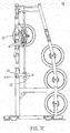
- the user can then operate the multifunctional leg training machine 10 to train different muscle groups of the legs, as shown in FIG. 8A .
- the user stands up in the multifunctional leg training machine 10 with the shoulders stopped at the bottom side of the cushion member 338 and the both hands holding the grips 337, thereafter, as shown in FIG.
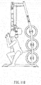
- the user bends the knees to get into the squat position so as to train the quadriceps muscles, gluteal muscles and the back muscles of the legs, or, as shown in FIG 8C , the user can get into the lunge position where one leg is positioned forward with knee bent and foot flat on the ground while the other leg is positioned behind to train the muscles of the thighs and buttocks, or, as shown in FIG 8D , the user can get into the calf-raise position to exercise the deep calf muscles of the lower legs.
- This vertical training method comprises the following steps as illustrated in FIGS. 8A-8D .
- the user can adjust the longitudinal sliding device set 31 to the desired elevational position to fit with tiptoe, standing, stride, squat, or any other position, and then move the transverse sliding device set 33 transversely between the opposing left and right sides of the multifunctional leg training machine 10 to train the muscle groups of the lower limbs.
- the user can operate the longitudinal sliding device set 31 and transverse sliding device set 33 of the weight-bearing mechanism 30 of the multifunctional leg training machine 10 to perform simple training exercises by moving the body transversely, or to perform mixed training exercises by moving the body transversely and vertically.
- the invention makes the training mode more varied, and allows the user exercise different muscle groups of the legs.
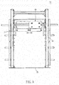
- This transverse training method comprises the following steps as illustrated in FIG 3 .
- a multifunctional leg training machine 10' in accordance with a second embodiment of the present invention is shown.
- This second embodiment is substantially similar to the aforesaid first embodiment with the exception that the longitudinal sliding device set 31 of this second embodiment comprises two pairs of vertical bars 311, two sliding sleeve sets 312, and a sliding bar 315 connected between the two sliding sleeve sets 312.
- the vertical bars 311 are respectively symmetrically affixed to the opposing left and right sides of the framework 20.
- the sliding sleeve sets 312 are respectively coupled to the vertical bars 311 and axially movable along the vertical bars 311.
- the sliding bar 315 has two opposite ends thereof respectively fixedly connected to the sliding sleeve sets 312 for the sliding of the transverse sliding device set 33. More specifically, each sliding sleeve set 312 comprises two sliding sleeves 313 and a link 314. The two sliding sleeves 313 are respectively and fixedly connected to the two opposite ends of the link 314, and respectively sleeved onto the respective vertical bars 311. The sliding bar 315 has the two opposite ends thereof respectively fixedly connected to the links 314 of the sliding sleeve sets 312.
- this second embodiment enhances the stability of the upward and downward movement of the longitudinal sliding device set 31 in the framework 20.
- the longitudinal sliding device set 31 further provides a stretcher bar 318 that is fixedly connected between the two links 314 in a parallel manner relative to the sliding bar 315.
- a stretcher bar 318 that is fixedly connected between the two links 314 in a parallel manner relative to the sliding bar 315.
- two or more than two stretcher bars 318 can be provided and connected between the two links 314 subject to actual requirements.
- a multifunctional leg training machine 10" in accordance with a third embodiment of the present invention is shown.
- This third embodiment is substantially similar to the aforesaid first embodiment with the exception that the framework 20 of the multifunctional leg training machine 10" of this third embodiment is relatively wider than that of the aforesaid first embodiment so that the multifunctional leg training machine 10" of this third embodiment is more practical for mixed transverse and longitudinal training exercises.
- the pulley holder frame 331 of the transverse sliding device set 33 exhibits an inverted U-shape; the cushion member 338 consists of two elongated cushion blocks that are respectively and fixedly connected to the opposing left and right sides of the pulley holder frame 331; the grips 337 are smoothly curved; and thus, the transverse sliding device set 33 is ergonomically designed, allowing the user to conduct training exercises more comfortable, and reducing the incidence of sports injuries.
- the user When using the multifunctional leg training machine 10" of the third embodiment of the present invention for conducting mixed training exercises, as illustrated in FIG. 11A , the user stands up on the left side in the multifunctional leg training machine 10" with the shoulders stopped at the bottom side of the cushion member 338 and the two hands holding the grips 337, and then, as illustrated in FIG. 11B , the user steps rightward to move toward the right side of the multifunctional leg training machine 10".
- the transverse sliding device set 33 is moved to the midpoint of the framework 20, and the longitudinal sliding device set 31 is synchronously lowered, and thus, the user is striding with one leg advanced. Thereafter, the user keeps moving rightwards and downwards to the right side of the framework 20.
- the user has one leg thereof in a squat position and the other leg thereof in an obliquely extended position, as illustrated in FIG. 11C and FIG. 11D .
- the user moves thelongitudinal sliding device set 31 upwards and resumes to the standing position, as illustrated in FIG 11E , and then, as illustrated in FIGS. 11F-11H , the user moves leftwards and downwards to the left side of the multifunctional leg training machine 10".
- the user can move the longitudinal sliding device set 31 and transverse sliding device set 33 of the weight-bearing mechanism 30 vertically and transversely in a synchronous manner between the opposing top and bottom sides and left and right sides of the of the framework 20 of the multifunctional leg training machine 10 ", completing the squatting action of striding, going down on the knees and standing up.
- This mixed transverse and vertical training method comprises the following steps as illustrated in FIGS. 11A-11H .
- the weightlifting training mode is more varied, allowing the user to perform a squat exercise, a lunge exercise, a calf-raise exercise, a simple transverse body movement exercise (see FIG 3 ), or a mixed training exercise of moving the body transversely and vertically (see FIGS. 11A-11H ) to fully train different muscle groups of the legs.
- the positioning mechanism 40 and the buffering mechanism 50 ensure a high level of safety and use convenience.
Landscapes
- Health & Medical Sciences (AREA)
- Orthopedic Medicine & Surgery (AREA)
- General Health & Medical Sciences (AREA)
- Physical Education & Sports Medicine (AREA)
- Life Sciences & Earth Sciences (AREA)
- Biophysics (AREA)
- Rehabilitation Tools (AREA)
Priority Applications (1)
| Application Number | Priority Date | Filing Date | Title |
|---|---|---|---|
| EP16170531.4A EP3246074B1 (fr) | 2016-05-20 | 2016-05-20 | Machine multifonctionnelle d'entraînement de jambe |
Applications Claiming Priority (1)
| Application Number | Priority Date | Filing Date | Title |
|---|---|---|---|
| EP16170531.4A EP3246074B1 (fr) | 2016-05-20 | 2016-05-20 | Machine multifonctionnelle d'entraînement de jambe |
Publications (2)
| Publication Number | Publication Date |
|---|---|
| EP3246074A1 true EP3246074A1 (fr) | 2017-11-22 |
| EP3246074B1 EP3246074B1 (fr) | 2019-10-30 |
Family
ID=56263472
Family Applications (1)
| Application Number | Title | Priority Date | Filing Date |
|---|---|---|---|
| EP16170531.4A Active EP3246074B1 (fr) | 2016-05-20 | 2016-05-20 | Machine multifonctionnelle d'entraînement de jambe |
Country Status (1)
| Country | Link |
|---|---|
| EP (1) | EP3246074B1 (fr) |
Cited By (4)
| Publication number | Priority date | Publication date | Assignee | Title |
|---|---|---|---|---|
| CN108478989A (zh) * | 2018-05-23 | 2018-09-04 | 山东迈宝赫健身器材有限公司 | 健身装置 |
| CN113180991A (zh) * | 2021-01-11 | 2021-07-30 | 河北医科大学第三医院 | 一种骨质疏松康复治疗装置 |
| CN113230602A (zh) * | 2021-06-16 | 2021-08-10 | 温州市中医院 | 术后康复锻炼设备 |
| CN114653027A (zh) * | 2020-12-23 | 2022-06-24 | 财团法人工业技术研究院 | 运动数据收集方法及系统 |
Citations (6)
| Publication number | Priority date | Publication date | Assignee | Title |
|---|---|---|---|---|
| US4795149A (en) * | 1988-01-13 | 1989-01-03 | Pearson Bruce E | Lunge training machine for body builders |
| US5050868A (en) * | 1990-03-16 | 1991-09-24 | Criterion Bodybuilding Equipment, Inc. | Leg training machine for body builders |
| US20070042876A1 (en) * | 2005-08-19 | 2007-02-22 | Recreation Supply, Inc. | Weight lifting power cage with slave rack |
| WO2007046078A1 (fr) * | 2005-10-21 | 2007-04-26 | Anthony Quinn | Appareil permettant d'exercer plusieurs parties du corps |
| CN201197861Y (zh) * | 2008-03-26 | 2009-02-25 | 约翰·维斯 | 重力训练器 |
| US20150306443A1 (en) * | 2014-04-28 | 2015-10-29 | Dave Peter Bruni, Jr. | Free weight simulating, weightlifting system |
-
2016
- 2016-05-20 EP EP16170531.4A patent/EP3246074B1/fr active Active
Patent Citations (6)
| Publication number | Priority date | Publication date | Assignee | Title |
|---|---|---|---|---|
| US4795149A (en) * | 1988-01-13 | 1989-01-03 | Pearson Bruce E | Lunge training machine for body builders |
| US5050868A (en) * | 1990-03-16 | 1991-09-24 | Criterion Bodybuilding Equipment, Inc. | Leg training machine for body builders |
| US20070042876A1 (en) * | 2005-08-19 | 2007-02-22 | Recreation Supply, Inc. | Weight lifting power cage with slave rack |
| WO2007046078A1 (fr) * | 2005-10-21 | 2007-04-26 | Anthony Quinn | Appareil permettant d'exercer plusieurs parties du corps |
| CN201197861Y (zh) * | 2008-03-26 | 2009-02-25 | 约翰·维斯 | 重力训练器 |
| US20150306443A1 (en) * | 2014-04-28 | 2015-10-29 | Dave Peter Bruni, Jr. | Free weight simulating, weightlifting system |
Cited By (8)
| Publication number | Priority date | Publication date | Assignee | Title |
|---|---|---|---|---|
| CN108478989A (zh) * | 2018-05-23 | 2018-09-04 | 山东迈宝赫健身器材有限公司 | 健身装置 |
| CN108478989B (zh) * | 2018-05-23 | 2023-12-01 | 山东迈宝赫健身器材有限公司 | 健身装置 |
| CN114653027A (zh) * | 2020-12-23 | 2022-06-24 | 财团法人工业技术研究院 | 运动数据收集方法及系统 |
| CN114653027B (zh) * | 2020-12-23 | 2023-07-25 | 财团法人工业技术研究院 | 运动数据收集方法及系统 |
| CN113180991A (zh) * | 2021-01-11 | 2021-07-30 | 河北医科大学第三医院 | 一种骨质疏松康复治疗装置 |
| CN113180991B (zh) * | 2021-01-11 | 2022-06-24 | 河北医科大学第三医院 | 一种骨质疏松康复治疗装置 |
| CN113230602A (zh) * | 2021-06-16 | 2021-08-10 | 温州市中医院 | 术后康复锻炼设备 |
| CN113230602B (zh) * | 2021-06-16 | 2022-06-17 | 温州市中医院 | 术后康复锻炼设备 |
Also Published As
| Publication number | Publication date |
|---|---|
| EP3246074B1 (fr) | 2019-10-30 |
Similar Documents
| Publication | Publication Date | Title |
|---|---|---|
| US9526938B2 (en) | Multifunctional leg training machine | |
| US6991588B1 (en) | Standing single leg press exercise machine | |
| EP3233221B1 (fr) | Appareil d'exercice | |
| US7232404B2 (en) | Abdominal exercise machine | |
| US20180000680A1 (en) | Unilateral leg press machine | |
| US20170239518A1 (en) | Hip Thrusting Exercise Machine | |
| US9199111B2 (en) | Exercise apparatus | |
| EP1748824B1 (fr) | Banc de musculation compact | |
| US11389690B2 (en) | Multi-use fitness machine and methods of use | |
| EP3246074B1 (fr) | Machine multifonctionnelle d'entraînement de jambe | |
| KR200486552Y1 (ko) | 철봉 운동기구 | |
| US7134989B2 (en) | Multifunction exercise machine | |
| EP2907548B1 (fr) | Dispositif d'exercice pour renforcer les muscles abdominaux | |
| JP5116064B2 (ja) | ベンチプレス・フルスクワット・懸垂装置 | |
| US20020098953A1 (en) | Exercise apparatus for performing squats | |
| CN211328001U (zh) | 一种普拉提运动训练器 | |
| TWI632936B (zh) | 蹲立健身器 | |
| CN106823258A (zh) | 一种平板卧推架 | |
| US6361481B1 (en) | Weight lifting simulator | |
| CN203507412U (zh) | 多功能哑铃凳 | |
| EP2892622B1 (fr) | Machine de gymnastique pour exercices de traction-flexion avec torsion du corps lors de séances de culture physique | |
| TW202600201A (zh) | 具有支撐墊與輔助靠墊的健身裝置 | |
| CN105597276A (zh) | 一种坐姿小腿提踵健身器 | |
| CN110180125A (zh) | 多功能拉伸力量训练器 | |
| CN221432031U (zh) | 一种髂腰肌训练器材 |
Legal Events
| Date | Code | Title | Description |
|---|---|---|---|
| PUAI | Public reference made under article 153(3) epc to a published international application that has entered the european phase |
Free format text: ORIGINAL CODE: 0009012 |
|
| STAA | Information on the status of an ep patent application or granted ep patent |
Free format text: STATUS: THE APPLICATION HAS BEEN PUBLISHED |
|
| AK | Designated contracting states |
Kind code of ref document: A1 Designated state(s): AL AT BE BG CH CY CZ DE DK EE ES FI FR GB GR HR HU IE IS IT LI LT LU LV MC MK MT NL NO PL PT RO RS SE SI SK SM TR |
|
| AX | Request for extension of the european patent |
Extension state: BA ME |
|
| STAA | Information on the status of an ep patent application or granted ep patent |
Free format text: STATUS: REQUEST FOR EXAMINATION WAS MADE |
|
| 17P | Request for examination filed |
Effective date: 20180509 |
|
| RBV | Designated contracting states (corrected) |
Designated state(s): AL AT BE BG CH CY CZ DE DK EE ES FI FR GB GR HR HU IE IS IT LI LT LU LV MC MK MT NL NO PL PT RO RS SE SI SK SM TR |
|
| GRAP | Despatch of communication of intention to grant a patent |
Free format text: ORIGINAL CODE: EPIDOSNIGR1 |
|
| STAA | Information on the status of an ep patent application or granted ep patent |
Free format text: STATUS: GRANT OF PATENT IS INTENDED |
|
| INTG | Intention to grant announced |
Effective date: 20190531 |
|
| GRAS | Grant fee paid |
Free format text: ORIGINAL CODE: EPIDOSNIGR3 |
|
| GRAA | (expected) grant |
Free format text: ORIGINAL CODE: 0009210 |
|
| STAA | Information on the status of an ep patent application or granted ep patent |
Free format text: STATUS: THE PATENT HAS BEEN GRANTED |
|
| AK | Designated contracting states |
Kind code of ref document: B1 Designated state(s): AL AT BE BG CH CY CZ DE DK EE ES FI FR GB GR HR HU IE IS IT LI LT LU LV MC MK MT NL NO PL PT RO RS SE SI SK SM TR |
|
| REG | Reference to a national code |
Ref country code: GB Ref legal event code: FG4D |
|
| REG | Reference to a national code |
Ref country code: CH Ref legal event code: EP |
|
| REG | Reference to a national code |
Ref country code: AT Ref legal event code: REF Ref document number: 1195520 Country of ref document: AT Kind code of ref document: T Effective date: 20191115 |
|
| REG | Reference to a national code |
Ref country code: DE Ref legal event code: R096 Ref document number: 602016023185 Country of ref document: DE |
|
| REG | Reference to a national code |
Ref country code: IE Ref legal event code: FG4D |
|
| REG | Reference to a national code |
Ref country code: LT Ref legal event code: MG4D |
|
| PG25 | Lapsed in a contracting state [announced via postgrant information from national office to epo] |
Ref country code: LV Free format text: LAPSE BECAUSE OF FAILURE TO SUBMIT A TRANSLATION OF THE DESCRIPTION OR TO PAY THE FEE WITHIN THE PRESCRIBED TIME-LIMIT Effective date: 20191030 Ref country code: SE Free format text: LAPSE BECAUSE OF FAILURE TO SUBMIT A TRANSLATION OF THE DESCRIPTION OR TO PAY THE FEE WITHIN THE PRESCRIBED TIME-LIMIT Effective date: 20191030 Ref country code: PL Free format text: LAPSE BECAUSE OF FAILURE TO SUBMIT A TRANSLATION OF THE DESCRIPTION OR TO PAY THE FEE WITHIN THE PRESCRIBED TIME-LIMIT Effective date: 20191030 Ref country code: NO Free format text: LAPSE BECAUSE OF FAILURE TO SUBMIT A TRANSLATION OF THE DESCRIPTION OR TO PAY THE FEE WITHIN THE PRESCRIBED TIME-LIMIT Effective date: 20200130 Ref country code: GR Free format text: LAPSE BECAUSE OF FAILURE TO SUBMIT A TRANSLATION OF THE DESCRIPTION OR TO PAY THE FEE WITHIN THE PRESCRIBED TIME-LIMIT Effective date: 20200131 Ref country code: LT Free format text: LAPSE BECAUSE OF FAILURE TO SUBMIT A TRANSLATION OF THE DESCRIPTION OR TO PAY THE FEE WITHIN THE PRESCRIBED TIME-LIMIT Effective date: 20191030 Ref country code: FI Free format text: LAPSE BECAUSE OF FAILURE TO SUBMIT A TRANSLATION OF THE DESCRIPTION OR TO PAY THE FEE WITHIN THE PRESCRIBED TIME-LIMIT Effective date: 20191030 Ref country code: BG Free format text: LAPSE BECAUSE OF FAILURE TO SUBMIT A TRANSLATION OF THE DESCRIPTION OR TO PAY THE FEE WITHIN THE PRESCRIBED TIME-LIMIT Effective date: 20200130 Ref country code: NL Free format text: LAPSE BECAUSE OF FAILURE TO SUBMIT A TRANSLATION OF THE DESCRIPTION OR TO PAY THE FEE WITHIN THE PRESCRIBED TIME-LIMIT Effective date: 20191030 Ref country code: PT Free format text: LAPSE BECAUSE OF FAILURE TO SUBMIT A TRANSLATION OF THE DESCRIPTION OR TO PAY THE FEE WITHIN THE PRESCRIBED TIME-LIMIT Effective date: 20200302 |
|
| REG | Reference to a national code |
Ref country code: NL Ref legal event code: MP Effective date: 20191030 |
|
| PG25 | Lapsed in a contracting state [announced via postgrant information from national office to epo] |
Ref country code: RS Free format text: LAPSE BECAUSE OF FAILURE TO SUBMIT A TRANSLATION OF THE DESCRIPTION OR TO PAY THE FEE WITHIN THE PRESCRIBED TIME-LIMIT Effective date: 20191030 Ref country code: IS Free format text: LAPSE BECAUSE OF FAILURE TO SUBMIT A TRANSLATION OF THE DESCRIPTION OR TO PAY THE FEE WITHIN THE PRESCRIBED TIME-LIMIT Effective date: 20200229 Ref country code: HR Free format text: LAPSE BECAUSE OF FAILURE TO SUBMIT A TRANSLATION OF THE DESCRIPTION OR TO PAY THE FEE WITHIN THE PRESCRIBED TIME-LIMIT Effective date: 20191030 |
|
| PG25 | Lapsed in a contracting state [announced via postgrant information from national office to epo] |
Ref country code: AL Free format text: LAPSE BECAUSE OF FAILURE TO SUBMIT A TRANSLATION OF THE DESCRIPTION OR TO PAY THE FEE WITHIN THE PRESCRIBED TIME-LIMIT Effective date: 20191030 |
|
| PG25 | Lapsed in a contracting state [announced via postgrant information from national office to epo] |
Ref country code: EE Free format text: LAPSE BECAUSE OF FAILURE TO SUBMIT A TRANSLATION OF THE DESCRIPTION OR TO PAY THE FEE WITHIN THE PRESCRIBED TIME-LIMIT Effective date: 20191030 Ref country code: DK Free format text: LAPSE BECAUSE OF FAILURE TO SUBMIT A TRANSLATION OF THE DESCRIPTION OR TO PAY THE FEE WITHIN THE PRESCRIBED TIME-LIMIT Effective date: 20191030 Ref country code: RO Free format text: LAPSE BECAUSE OF FAILURE TO SUBMIT A TRANSLATION OF THE DESCRIPTION OR TO PAY THE FEE WITHIN THE PRESCRIBED TIME-LIMIT Effective date: 20191030 Ref country code: CZ Free format text: LAPSE BECAUSE OF FAILURE TO SUBMIT A TRANSLATION OF THE DESCRIPTION OR TO PAY THE FEE WITHIN THE PRESCRIBED TIME-LIMIT Effective date: 20191030 Ref country code: ES Free format text: LAPSE BECAUSE OF FAILURE TO SUBMIT A TRANSLATION OF THE DESCRIPTION OR TO PAY THE FEE WITHIN THE PRESCRIBED TIME-LIMIT Effective date: 20191030 |
|
| REG | Reference to a national code |
Ref country code: DE Ref legal event code: R097 Ref document number: 602016023185 Country of ref document: DE |
|
| REG | Reference to a national code |
Ref country code: AT Ref legal event code: MK05 Ref document number: 1195520 Country of ref document: AT Kind code of ref document: T Effective date: 20191030 |
|
| PG25 | Lapsed in a contracting state [announced via postgrant information from national office to epo] |
Ref country code: SM Free format text: LAPSE BECAUSE OF FAILURE TO SUBMIT A TRANSLATION OF THE DESCRIPTION OR TO PAY THE FEE WITHIN THE PRESCRIBED TIME-LIMIT Effective date: 20191030 Ref country code: SK Free format text: LAPSE BECAUSE OF FAILURE TO SUBMIT A TRANSLATION OF THE DESCRIPTION OR TO PAY THE FEE WITHIN THE PRESCRIBED TIME-LIMIT Effective date: 20191030 Ref country code: IT Free format text: LAPSE BECAUSE OF FAILURE TO SUBMIT A TRANSLATION OF THE DESCRIPTION OR TO PAY THE FEE WITHIN THE PRESCRIBED TIME-LIMIT Effective date: 20191030 |
|
| PLBE | No opposition filed within time limit |
Free format text: ORIGINAL CODE: 0009261 |
|
| STAA | Information on the status of an ep patent application or granted ep patent |
Free format text: STATUS: NO OPPOSITION FILED WITHIN TIME LIMIT |
|
| 26N | No opposition filed |
Effective date: 20200731 |
|
| PG25 | Lapsed in a contracting state [announced via postgrant information from national office to epo] |
Ref country code: SI Free format text: LAPSE BECAUSE OF FAILURE TO SUBMIT A TRANSLATION OF THE DESCRIPTION OR TO PAY THE FEE WITHIN THE PRESCRIBED TIME-LIMIT Effective date: 20191030 Ref country code: AT Free format text: LAPSE BECAUSE OF FAILURE TO SUBMIT A TRANSLATION OF THE DESCRIPTION OR TO PAY THE FEE WITHIN THE PRESCRIBED TIME-LIMIT Effective date: 20191030 |
|
| PG25 | Lapsed in a contracting state [announced via postgrant information from national office to epo] |
Ref country code: MC Free format text: LAPSE BECAUSE OF FAILURE TO SUBMIT A TRANSLATION OF THE DESCRIPTION OR TO PAY THE FEE WITHIN THE PRESCRIBED TIME-LIMIT Effective date: 20191030 Ref country code: CH Free format text: LAPSE BECAUSE OF NON-PAYMENT OF DUE FEES Effective date: 20200531 Ref country code: LI Free format text: LAPSE BECAUSE OF NON-PAYMENT OF DUE FEES Effective date: 20200531 |
|
| PG25 | Lapsed in a contracting state [announced via postgrant information from national office to epo] |
Ref country code: LU Free format text: LAPSE BECAUSE OF NON-PAYMENT OF DUE FEES Effective date: 20200520 |
|
| PG25 | Lapsed in a contracting state [announced via postgrant information from national office to epo] |
Ref country code: IE Free format text: LAPSE BECAUSE OF NON-PAYMENT OF DUE FEES Effective date: 20200520 |
|
| PG25 | Lapsed in a contracting state [announced via postgrant information from national office to epo] |
Ref country code: TR Free format text: LAPSE BECAUSE OF FAILURE TO SUBMIT A TRANSLATION OF THE DESCRIPTION OR TO PAY THE FEE WITHIN THE PRESCRIBED TIME-LIMIT Effective date: 20191030 Ref country code: MT Free format text: LAPSE BECAUSE OF FAILURE TO SUBMIT A TRANSLATION OF THE DESCRIPTION OR TO PAY THE FEE WITHIN THE PRESCRIBED TIME-LIMIT Effective date: 20191030 Ref country code: CY Free format text: LAPSE BECAUSE OF FAILURE TO SUBMIT A TRANSLATION OF THE DESCRIPTION OR TO PAY THE FEE WITHIN THE PRESCRIBED TIME-LIMIT Effective date: 20191030 |
|
| PG25 | Lapsed in a contracting state [announced via postgrant information from national office to epo] |
Ref country code: MK Free format text: LAPSE BECAUSE OF FAILURE TO SUBMIT A TRANSLATION OF THE DESCRIPTION OR TO PAY THE FEE WITHIN THE PRESCRIBED TIME-LIMIT Effective date: 20191030 |
|
| REG | Reference to a national code |
Ref country code: DE Ref legal event code: R082 Ref document number: 602016023185 Country of ref document: DE Representative=s name: STRAUS, ALEXANDER, DIPL.-CHEM.UNIV. DR.PHIL., DE |
|
| PGFP | Annual fee paid to national office [announced via postgrant information from national office to epo] |
Ref country code: DE Payment date: 20250528 Year of fee payment: 10 |
|
| PGFP | Annual fee paid to national office [announced via postgrant information from national office to epo] |
Ref country code: GB Payment date: 20250522 Year of fee payment: 10 |
|
| PGFP | Annual fee paid to national office [announced via postgrant information from national office to epo] |
Ref country code: BE Payment date: 20250520 Year of fee payment: 10 |
|
| PGFP | Annual fee paid to national office [announced via postgrant information from national office to epo] |
Ref country code: FR Payment date: 20250521 Year of fee payment: 10 |