EP3246096B1 - Sprühvorrichtung und verwendung dieser vorrichtung - Google Patents
Sprühvorrichtung und verwendung dieser vorrichtung Download PDFInfo
- Publication number
- EP3246096B1 EP3246096B1 EP17175982.2A EP17175982A EP3246096B1 EP 3246096 B1 EP3246096 B1 EP 3246096B1 EP 17175982 A EP17175982 A EP 17175982A EP 3246096 B1 EP3246096 B1 EP 3246096B1
- Authority
- EP
- European Patent Office
- Prior art keywords
- front wall
- spraying device
- holes
- side wall
- pusher
- Prior art date
- Legal status (The legal status is an assumption and is not a legal conclusion. Google has not performed a legal analysis and makes no representation as to the accuracy of the status listed.)
- Active
Links
Images


Classifications
-
- B—PERFORMING OPERATIONS; TRANSPORTING
- B05—SPRAYING OR ATOMISING IN GENERAL; APPLYING FLUENT MATERIALS TO SURFACES, IN GENERAL
- B05B—SPRAYING APPARATUS; ATOMISING APPARATUS; NOZZLES
- B05B1/00—Nozzles, spray heads or other outlets, with or without auxiliary devices such as valves, heating means
- B05B1/14—Nozzles, spray heads or other outlets, with or without auxiliary devices such as valves, heating means with multiple outlet openings; with strainers in or outside the outlet opening
-
- B—PERFORMING OPERATIONS; TRANSPORTING
- B05—SPRAYING OR ATOMISING IN GENERAL; APPLYING FLUENT MATERIALS TO SURFACES, IN GENERAL
- B05B—SPRAYING APPARATUS; ATOMISING APPARATUS; NOZZLES
- B05B1/00—Nozzles, spray heads or other outlets, with or without auxiliary devices such as valves, heating means
- B05B1/14—Nozzles, spray heads or other outlets, with or without auxiliary devices such as valves, heating means with multiple outlet openings; with strainers in or outside the outlet opening
- B05B1/18—Roses; Shower heads
- B05B1/185—Roses; Shower heads characterised by their outlet element; Mounting arrangements therefor
-
- B—PERFORMING OPERATIONS; TRANSPORTING
- B65—CONVEYING; PACKING; STORING; HANDLING THIN OR FILAMENTARY MATERIAL
- B65D—CONTAINERS FOR STORAGE OR TRANSPORT OF ARTICLES OR MATERIALS, e.g. BAGS, BARRELS, BOTTLES, BOXES, CANS, CARTONS, CRATES, DRUMS, JARS, TANKS, HOPPERS, FORWARDING CONTAINERS; ACCESSORIES, CLOSURES, OR FITTINGS THEREFOR; PACKAGING ELEMENTS; PACKAGES
- B65D83/00—Containers or packages with special means for dispensing contents
- B65D83/14—Containers for dispensing liquid or semi-liquid contents by internal gaseous pressure, i.e. aerosol containers comprising propellant
- B65D83/75—Aerosol containers not provided for in groups B65D83/16 - B65D83/74
- B65D83/753—Aerosol containers not provided for in groups B65D83/16 - B65D83/74 characterised by details or accessories associated with outlets
-
- B—PERFORMING OPERATIONS; TRANSPORTING
- B05—SPRAYING OR ATOMISING IN GENERAL; APPLYING FLUENT MATERIALS TO SURFACES, IN GENERAL
- B05B—SPRAYING APPARATUS; ATOMISING APPARATUS; NOZZLES
- B05B11/00—Single-unit hand-held apparatus in which flow of contents is produced by the muscular force of the operator at the moment of use
- B05B11/01—Single-unit hand-held apparatus in which flow of contents is produced by the muscular force of the operator at the moment of use characterised by the means producing the flow
- B05B11/10—Pump arrangements for transferring the contents from the container to a pump chamber by a sucking effect and forcing the contents out through the dispensing nozzle
Definitions
- the present invention relates to a spray device and to a use of this device.
- the document US-A-6 145 712 describes an example of such a spray device, in which the front face of the spray nozzle has a single central hole.
- the spray nozzles which are conventionally mounted on pumps or on spray valves, have the drawback of causing a large dispersion in the diameter of the droplets of sprayed fluid.
- the fractionation of the fluid product into fine droplets is obtained by a dynamic phenomenon which is particularly difficult to control, generally consisting in creating a vortex in the inner chamber of the nozzle and in splitting the fluid. fluid product in fine droplets when it exits at very high speed through the central hole.
- spray devices are described in WO03 / 020436A , EP 1 698 399 A , EP0 613 836 A , WO 02/0201981 A , JP 2002 186882A and US 6 341 735 B1 .
- the sprayed product consists of droplets having diameters between 5 ⁇ m and 300 ⁇ m.
- This dispersion may prove to be undesirable when it is desired to spray droplets of substantially homogeneous sizes. For example, one may wish to spray small droplets for inhaling medicinal treatments of the bronchi, or else one may wish to spray larger size drops for cosmetic or perfume applications, so that the droplets penetrate the least. possible in the user's bronchi.
- droplets of very different sizes also follow very different paths, which is detrimental for a controlled application of the sprayed product.
- oversized droplets may fall on the user's clothing instead of being projected onto the skin, risking indelible stains. .
- the object of the present invention is in particular to overcome these drawbacks.
- the invention provides a spray device of the aforementioned type in which the front wall comprises a plurality of calibrated holes each having a diameter between 1 and 100 ⁇ m, the diameter of each hole not differing by more than 20%. an average of the diameters of the various holes, the front wall being elastically deformable between a state of rest, in which said front wall is flat, and an actuation state when the fluid under pressure is transferred into the inner chamber, in wherein said front wall has an outwardly facing convexity.
- the term “diameter” does not necessarily imply that this section is circular.
- the holes in the front face could, where appropriate, have a polygonal section, for example square, without departing from the scope of the present invention.
- the aforementioned diameter would be the diameter equivalent of the hole, that is to say the diameter of a circular hole having a section of the same area as the polygonal hole. If the holes are not of constant section along their length, the diameter in question is the diameter of the minimum section of the holes.
- the size of the droplets sprayed by the spraying device is controlled and good homogeneity of this size of the droplets is ensured.
- the aforementioned arrangements also make it possible at least partially to overcome the pressure differences with which the fluid is fed into the interior chamber of the spray nozzle, since experience shows that the size of the droplets obtained by virtue of the The present invention is not very dependent on this pressure (the pressure differences in question may arise, for example, from differences in the actuating force of a user if the fluid product is supplied by means of a manual pump, or even when the fluid product is supplied through a valve from a pressurized product tank, the pressure differences in question may come from the fact that the tank has already been partially emptied by previous uses of the spray device).
- the invention aims to improve control over the shape of the aerosol obtained at the outlet of the spray nozzle while allowing simplified production of the calibrated holes.
- the front wall is elastically deformable between a state of rest, in which said front wall is flat, and an actuation state when fluid under pressure is transferred into the inner chamber, in which said front wall has a convexity turned outwards.
- the holes can be made in a simple manner in the flat front wall, each hole possibly having an axis which extends in a plane parallel to a central axis perpendicular to the front wall.
- the axes of the holes move away from the central axis so as to present an outward divergence and the fluid product can be sprayed in the form of 'an aerosol with a high opening angle.
- the invention aims to improve control over the distribution of droplets and the shape of the aerosol.
- the holes in the front wall are distributed around a center, each hole extends along an axis inclined with respect to the normal to said front wall at the level of said hole, said axis and said normal defining a plane substantially tangent to a circle centered on said central point and passing through the hole, and the axes of all the holes having an inclination with respect to the corresponding normal, and said axes of all the holes holes being inclined in the direction of the same angular direction around said central point so as to generate a swirling aerosol when fluid is sprayed from said nozzle.
- the aerosol may have, in the vicinity of the spray nozzle, a first substantially conical portion having a high opening angle and a second portion substantially symmetrical with respect to the central axis of the nozzle.
- a subject of the invention is also the use of a spraying device as defined above, for spraying a non-gaseous fluid product.
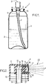
- the figure 1 represents a spraying device 1 suitable for spraying a non-gaseous fluid product 2 contained in a reservoir 3.
- the fluid product in question can be a liquid or semi-liquid product, for example a pharmaceutical product, a cosmetic product, a perfume product Or other.
- the dynamic viscosity of the fluid 2 is generally less than 50 cps (centipoise) at 20 ° C.
- the spraying device 1 further comprises a dispensing device 4 which is fixed so known to a neck 5 of the reservoir 3 at the upper end of said reservoir.
- the dispensing device 4 can for example be a manual spray pump or else a spray valve, in which case the reservoir 3 is under pressure.
- the dispensing device 4 comprises a fluid product inlet 6, oriented downwards, which communicates with the bottom of the reservoir 3 via a dip tube 7, and a hollow actuating rod 8 that protrudes upwards.
- a push button 9 is fitted to the upper end of the actuating rod 8, and serves both for actuating the dispensing device 4 and for the output of the sprayed fluid, output which takes place through the actuating rod 8, according to the arrow 10 shown on the figure 2 .
- the dispensing device shown in figure 1 could, alternatively, be used in the inverted position, that is to say the bottom of the tank 3 facing upwards.
- the distribution device 4 would not include a dip tube 7.
- the pusher 9 can for example be molded in a single piece of plastic, in particular a polyolefin, for example polypropylene or the like.
- the pusher 9 comprises a substantially horizontal upper wall 11 and a substantially cylindrical and vertical skirt 12 which extends from the periphery of the upper wall 11.
- the pusher 9 further comprises a central well 13 which extends vertically downward from the upper wall 11, in the center of the side wall 12. The upper end of the actuating rod 8 is fitted. in the central well 13.
- a lateral passage 14 which communicates with a housing for receiving the nozzle 15 of substantially cylindrical shape, extending substantially horizontally along a central axis X and opening outwards from the pusher 9.
- the side wall 18 of the spray nozzle 16 may include, at its end opposite the front wall 17, an annular gaudron 19 which projects radially outwards and which penetrates into the material of the pusher 9 for anchor spray tip 16 in nozzle housing 15.
- the spray nozzle 16 delimits, with the pusher 9, an interior chamber 20 which communicates with the aforementioned passage 14 and which receives the fluid product to be sprayed upon actuation of the dispensing device 4.
- the pusher 9 may include a core 21 which protrudes inside the side wall 18 of the spray nozzle to limit the volume of this interior chamber 20.
- the front wall 17 of the spray nozzle has a plurality of holes 22 which are distributed over the surface of said front face.
- the holes 22 can be 10 to 1000 in number, for example.
- the diameter of each hole 22 is generally between 1 and 100 ⁇ m, all the holes 22 being substantially of the same diameter.
- the diameter of each hole 22 does not differ from the average value of the diameters of the various holes 22 by more than 20% and advantageously, the diameter of each hole 22 does not differ from said average value by more than 10%.
- the holes 22 may be of substantially cylindrical shape with a circular section, but they could optionally have a polygonal section, for example square, in which case the aforementioned diameter would be the equivalent diameter of the hole, that is to say the diameter d 'a circular hole having a section of the same area as the polygonal hole.
- the front wall 17 may have a convex shape with a concavity facing inward, as in the example shown in FIG. figure 3 , but said front wall may be flat or have any other desired shape.
- the front wall 17 may have a thickness e generally between 0.08 and 1.5 mm, in particular between 0.2 and 0.4 mm.
- the holes 22 may have a constant section, as in the example shown, but the holes 22 could, where appropriate, have portions flared inward and / or outward, in which case the length of the holes 22 to be taken into account. account would be the length in which these holes have a constant section and the diameter to be taken into account would be the diameter of the minimum section.
- the length of the holes 22 in their part with constant section is generally between 0.08 and 0.5 mm, advantageously between 0.08 and 0.3 mm, and more advantageously still between 0.08 and 0.2 mm, in particular equal to approximately 0.1 mm.
- the pusher 9 when a user presses the pusher 9, the latter actuates the dispensing device 4, which supplies the inner chamber 20 of the nozzle with pressurized fluid, at a pressure generally less than 7 bars, for example order of 5 bars.
- the fluid product is expelled through the calibrated holes 22 of the front wall 17, which produces an aerosol 23 of fine droplets of relatively homogeneous size and little dependent on the exact value of the pressure of the fluid product in the interior chamber 20.
- the spray nozzle 16 differs from the spray nozzle previously described in that the front wall 17b is elastically deformable between a rest state shown in the figure. figure 4 and an actuation state shown in figure 5 , when the pressurized fluid product is transferred into the inner chamber 20.
- the front wall 17b in the rest state, extends in a plane perpendicular to the central axis X. And in the actuation state, the front wall 17b has a convexity facing outwardly. so, for example, to have the shape of a spherical cap.
- the front wall 17b is flat.
- This arrangement makes it possible to produce in a simple manner the holes 22 having an axis which extends, for example, along a normal to the front wall 17b, parallel to the central axis X.
- the pressurized fluid product is transferred into the inner chamber 20 exerting a force on the front wall 17b so as to cause it to pass into the actuation state.
- the axes of the holes 22 move away from the central axis X so as to present an outward divergence.
- the fluid product is expelled through the holes 22 diverging from the front wall 17b, which produces an aerosol 23 of fine droplets of relatively homogeneous size, the aerosol 23 being substantially conical with a high cone angle ⁇ .
- the side wall 18 is a separate part of the pusher 9, secured to the pusher 9, and the front wall 17b integrally with the side wall 18 is made of the same material as the side wall 18.
- the wall front 17b has a thickness e of between 0.05 and 0.10 mm.
- the realization of the elastically deformable front wall 17b according to the second embodiment can be provided in a complementary or independent manner to the previously described embodiment in which all the holes 22 have substantially the same diameter, between 1 and 100 ⁇ m, and the diameter of each hole 22 does not differ from the average value of the diameters of the various holes 22 by more than 20% and advantageously.
- the side wall 18a can be formed in one piece with the pusher 9.
- the front wall 17c can thus be made in one piece with the pusher 9 and be in the same material as the pusher 9.
- the core 21 can then be an attached part and secured to the pusher 9 in an appropriate manner.
- the front wall 17c may be deformable.
- the front wall 17c may have a thickness of between 0.10 and 0.20 mm.
- the spray nozzle 16 differs from the spray nozzle described above in that the front wall 17a is made of a material different from the side wall 18 of the nozzle, the side wall 18 being a separate part from the pusher 9, secured with pusher 9.
- the front wall 17a can be made of a material chosen from among silicon, glass, metals and their alloys, ceramics or polymers, while the side wall 18 is made of plastic as in the previous example. , said side wall 18 being able to be overmolded around the periphery of the front wall 17a.
- the front wall 17a is flat, but could be convex as in the embodiment of figures 2 and 3 or have any other form.
- the front wall 17a can be deformable.
- the front wall 17a can be produced in the form of a complex comprising at least one layer of polymer and optionally one layer of metallic material.
- the complex can have a thickness between 0.025 and 0.120 mm.
- each hole 22 of the front wall 17 of the spray nozzle extends along an axis X2 inclined with respect to the normal X1 to said front wall at the level of said hole 22.
- the axis X2 and the normal X1 define a plane substantially tangent to a circle C centered on the central point of the front wall 17 and passing through the hole 22.
- the axes X2 of all the holes 22 have an inclination ⁇ of the same direction compared to the corresponding normal X1. This inclination can advantageously be the same for all the holes, and be between 10 and 60 °, for example, in particular of the order of 30 °.
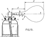
- the holes 22 are all inclined in the same angular direction 24 ( figure 6 ), when an aerosol A is generated by the spray nozzle (see figure 8 ), the path v followed by each droplet of liquid in the aerosol is a swirling path around the central axis X of the spray nozzle.
- the aerosol A has a first part b1, in the vicinity of the spray nozzle, in which the liquid droplets are driven at a high speed of advance and which is substantially conical having a relatively high opening angle ⁇ , for example example of the order of 20 ° or more.
- the aerosol A has a second part p2 forming a cloud in which the liquid droplets have a lower forward speed than in the first part p1. Thanks to the swirling movement of the liquid droplets, the second part b2 of the aerosol remains relatively symmetrical with respect to the X axis.
- the front wall 17 is elastically deformable.
- the calibrated holes 22 can then be made in a simple manner with an axis X2 which extends in a plane parallel to the central axis X of the spray nozzle 16.
- the divergence of the axis X2 calibrated holes 22 can be obtained when actuating the pusher to increase the opening angle ⁇ of the first part of the aerosol A.
Landscapes
- Chemical & Material Sciences (AREA)
- Dispersion Chemistry (AREA)
- Engineering & Computer Science (AREA)
- Mechanical Engineering (AREA)
- Containers And Packaging Bodies Having A Special Means To Remove Contents (AREA)
- Nozzles (AREA)
Claims (17)
- Manuelle Zerstäubungsvorrichtung, umfassend:- einen Stößel (9), der manuell betätigbar ist, wobei der Stößel eine Zerstäubungsdüse (16) umfasst, wobei die Zerstäubungsdüse eine innere Kammer (20) umfasst, die angepasst ist, um ein flüssiges, nicht gasförmiges Produkt unter Druck aufzunehmen und nach außen durch eine perforierte Vorderwand (17) begrenzt ist,- ein Reservoir (3) für das zu zerstäubende, flüssige Produkt,- und eine Verteilungsvorrichtung (4), die durch den Stößel mechanisch betätigbar ist und angepasst ist, um das flüssige Produkt von dem Reservoir (3) bis zu der inneren Kammer (20) der Düse zu übertragen,- die Vorderwand (17) eine Vielzahl von kalibrierten Löchern (22) umfasst, die jeweils einen Durchmesser aufweisen, der zwischen 1 und 100 µm liegt, wobei der Durchmesser von jedem Loch von einem Mittelwert der Durchmesser von unterschiedlichen Löchern nicht um mehr als 20 % abweicht- die Vorderwand (17b; 17c) elastisch verformbar ist zwischen einem Ruhezustand, in dem die Vorderwand (17b; 17c) flach ist, und einem Betätigungszustand, wenn das flüssige Produkt unter Druck in die innere Kammer (20) übertragen wird, in dem die Vorderwand (17b; 17c) eine nach außen weisende Konvexität aufweist.
- Zerstäubungsvorrichtung nach Anspruch 1, wobei die Vorderwand (17b; 17c) im Betätigungszustand die Form einer Kugelschale aufweist.
- Zerstäubungsvorrichtung nach einem der Ansprüche 1 bis 2, wobei die Vorderwand (17) integral mit der seitlichen Umfangswand (18; 18a) ausgebildet ist, die sich längs entlang der zentralen Achse (X) im Wesentlichen senkrecht zu der Vorderwand (17) erstreckt.
- Zerstäubungsvorrichtung nach Anspruch 3, wobei die Vorderwand (17) mit der seitlichen Wand (18; 18a) aus einem einzigen Stück gebildet ist.
- Zerstäubungsvorrichtung nach Anspruch 4, wobei die seitliche Wand (18a) aus einem einzigen Stück mit dem Stößel gebildet ist und die Vorderwand (17b; 17c) eine Dicke zwischen 0,10 und 0,20 mm aufweist.
- Zerstäubungsvorrichtung nach Anspruch 4, wobei die seitliche Wand (18) ein unterschiedliches Stück als der Stößel ist, der mit dem Stößel (9) fest verbunden ist, und die Vorderwand (17b; 17c) eine Dicke zwischen 0,05 und 0,10 mm aufweist.
- Zerstäubungsvorrichtung nach Anspruch 3, wobei die Vorderwand (17a) ein unterschiedliches Stück als die seitliche Wand (18; 18a) ist, die fest mit der seitlichen Wand (18; 18a) verbunden ist.
- Zerstäubungsvorrichtung nach Anspruch 7, wobei die Vorderwand (17a) aus einem Material hergestellt ist, das aus Silizium, Glas, Metallen und deren Legierungen, Keramiken, Polymeren ausgewählt ist.
- Zerstäubungsvorrichtung nach Anspruch 7 oder Anspruch 8, wobei die seitliche Wand (18) aus Kunststoffmaterial hergestellt ist und um die Vorderwand angeformt ist.
- Zerstäubungsvorrichtung nach Anspruch 7, wobei die Vorderwand (17a) in der Form eines Komplexes hergestellt ist, der mindestens eine Schicht aus Polymer umfasst.
- Zerstäubungsvorrichtung nach Anspruch 10, wobei der Komplex eine Schicht aus Polyester umfasst.
- Zerstäubungsvorrichtung nach Anspruch 11, wobei der Komplex weiter eine Beschichtung aus heißklebendem Material aufweist, wobei die Vorderwand (17a) an der seitlichen Wand (18; 18a) anhaftet.
- Zerstäubungsvorrichtung nach Anspruch 11, wobei der Komplex weiter mindestens eine Schicht aus Polymer umfasst, das aus Polyethylen und Polypropylen ausgewählt ist, wobei die Vorderwand (17a) an der seitlichen Wand (18; 18a) angeschweißt ist.
- Zerstäubungsvorrichtung nach einem der Ansprüche 10 bis 13, wobei der Komplex weiter mindestens eine Schicht aus metallischem Material umfasst.
- Zerstäubungsvorrichtung nach einem der Ansprüche 10 bis 13, wobei der Komplex eine Dicke zwischen 0,025 und 0,120 mm aufweist.
- Zerstäubungsvorrichtung nach einem der Ansprüche 1 bis 15, wobei der Durchmesser eines jeden Lochs (22) der Vorderwand von dem Mittelwert nicht um mehr als 10 % abweicht.
- Zerstäubungsvorrichtung nach einem der Ansprüche 1 bis 16, wobei die Löcher (22) der Vorderwand (17) um einen Mittelpunkt (O) herum verteilt sind, jedes Loch (22) sich entlang einer Achse (X2) erstreckt, die in Bezug auf die Normale (X1) zu der Vorderwand im Bereich des Lochs (22) geneigt ist, wobei die Achse (X2) und die Normale (X1) eine Ebene definieren, die im Wesentlichen tangential zu einem Kreis (C) ist, der auf dem Mittelpunkt (O) zentriert ist und durch das Loch (22) verläuft, wobei die Achsen (X2) aller Löcher eine Neigung (Y) in Bezug auf die entsprechende Normale (X1) aufweisen und die Achsen (X2) aller Löcher (22) alle entlang einer gleichen Winkelrichtung (24) um den Mittelpunkt (O) geneigt sind, um ein wirbelndes Aerosol (A) zu erzeugen, wenn flüssiges Produkt aus der Düse zerstäubt wird.
Applications Claiming Priority (3)
| Application Number | Priority Date | Filing Date | Title |
|---|---|---|---|
| FR0606259A FR2903328B1 (fr) | 2006-07-10 | 2006-07-10 | Buse de pulverisation, dispositif de pulverisation et utilisation de ce dispositif. |
| FR0700485A FR2903329B3 (fr) | 2006-07-10 | 2007-01-24 | Buse de pulverisation, dispositif de pulverisation et utilisation de ce dispositif. |
| EP07111772.5A EP1878507B2 (de) | 2006-07-10 | 2007-07-04 | Sprühvorrichtung und Verwendung dieser Vorrichtung |
Related Parent Applications (2)
| Application Number | Title | Priority Date | Filing Date |
|---|---|---|---|
| EP07111772.5A Division EP1878507B2 (de) | 2006-07-10 | 2007-07-04 | Sprühvorrichtung und Verwendung dieser Vorrichtung |
| EP07111772.5A Division-Into EP1878507B2 (de) | 2006-07-10 | 2007-07-04 | Sprühvorrichtung und Verwendung dieser Vorrichtung |
Publications (2)
| Publication Number | Publication Date |
|---|---|
| EP3246096A1 EP3246096A1 (de) | 2017-11-22 |
| EP3246096B1 true EP3246096B1 (de) | 2021-09-08 |
Family
ID=38510412
Family Applications (2)
| Application Number | Title | Priority Date | Filing Date |
|---|---|---|---|
| EP07111772.5A Active EP1878507B2 (de) | 2006-07-10 | 2007-07-04 | Sprühvorrichtung und Verwendung dieser Vorrichtung |
| EP17175982.2A Active EP3246096B1 (de) | 2006-07-10 | 2007-07-04 | Sprühvorrichtung und verwendung dieser vorrichtung |
Family Applications Before (1)
| Application Number | Title | Priority Date | Filing Date |
|---|---|---|---|
| EP07111772.5A Active EP1878507B2 (de) | 2006-07-10 | 2007-07-04 | Sprühvorrichtung und Verwendung dieser Vorrichtung |
Country Status (5)
| Country | Link |
|---|---|
| US (1) | US7748647B2 (de) |
| EP (2) | EP1878507B2 (de) |
| BR (1) | BRPI0702942B1 (de) |
| FR (1) | FR2903329B3 (de) |
| RU (1) | RU2007125994A (de) |
Families Citing this family (35)
| Publication number | Priority date | Publication date | Assignee | Title |
|---|---|---|---|---|
| FR2903329B3 (fr) † | 2006-07-10 | 2008-10-03 | Rexam Dispensing Systems Sas | Buse de pulverisation, dispositif de pulverisation et utilisation de ce dispositif. |
| DE102007049614B4 (de) * | 2007-03-15 | 2015-03-05 | Aptar Dortmund Gmbh | Abgabevorrichtung |
| ES2436002T3 (es) | 2008-06-20 | 2013-12-26 | Aptar Dortmund Gmbh | Dispositivo de distribución |
| DE102008038654B4 (de) | 2008-08-12 | 2019-09-19 | Aptar Dortmund Gmbh | Abgabekopf mit schwenkbarem Ventilelement |
| GB2466631A (en) * | 2008-10-21 | 2010-07-07 | Philip Alan Durrant | A spray device for atomising fluids having at least three nozzles with a restriction |
| DE102009030627B4 (de) * | 2009-06-25 | 2020-03-12 | Aptar Dortmund Gmbh | Ventil und Abgabevorrichtung |
| FR2971772B1 (fr) * | 2011-02-17 | 2013-03-22 | Valois Sas | Dispositif de distribution de produit fluide. |
| DE102013202531B3 (de) | 2013-02-16 | 2014-05-28 | Aptar Radolfzell Gmbh | Spender zum Austrag von Flüssigkeiten |
| EP3157681A1 (de) * | 2014-06-20 | 2017-04-26 | Medspray B.V. | Aerosol- oder sprühvorrichtung, sprühdüseneinheit und verfahren zur herstellung davon |
| EP3095522A1 (de) * | 2015-05-20 | 2016-11-23 | Aptar Radolfzell GmbH | Inhalationseinrichtung, inhalationseinrichtungs-set und düsenplatte hierfür |
| JP6634255B2 (ja) * | 2015-09-30 | 2020-01-22 | 株式会社吉野工業所 | ノズルチップを有する吐出器 |
| CN108602080B (zh) | 2015-12-04 | 2022-06-24 | 美德斯普瑞公司 | 流体喷雾器 |
| WO2017095219A1 (en) | 2015-12-04 | 2017-06-08 | Medspray Bv | Spray device and spray nozzle body |
| FR3048236B1 (fr) * | 2016-02-29 | 2019-07-12 | Albea Le Treport | Systeme de distribution de produit pour flacon |
| WO2018026932A1 (en) * | 2016-08-03 | 2018-02-08 | Becker Todd H | Method and system of a networked scent diffusion device |
| FR3059573B1 (fr) * | 2016-12-02 | 2019-01-25 | Aptar France Sas | Tete de distribution de produit fluide |
| WO2019106321A1 (fr) | 2017-12-01 | 2019-06-06 | Aptar France Sas | Tête de distribution de produit fluide |
| WO2019106315A1 (fr) | 2017-12-01 | 2019-06-06 | Aptar France Sas | Procédé de fabrication d'une paroi de distribution |
| WO2019038500A1 (fr) | 2017-08-24 | 2019-02-28 | Safran Aircraft Engines | Pale pour turbomachine et son procede de fabrication |
| EP3717137B1 (de) | 2017-12-01 | 2025-08-13 | Aptar France SAS | Spenderkopf für ein flüssigprodukt |
| EP3717135B1 (de) | 2017-12-01 | 2023-01-25 | Aptar France SAS | Kopf zur ausgabe eines flüssigprodukts und zugehöriges verfahren |
| US11305142B2 (en) * | 2018-01-12 | 2022-04-19 | Carrier Corporation | End cap agent nozzle |
| US11691161B2 (en) | 2018-05-02 | 2023-07-04 | Innovative Product Brands, Inc. | Sprayer with a six-hole spray pattern |
| EP3569318A1 (de) | 2018-05-16 | 2019-11-20 | Medspray B.V. | Sprühvorrichtung zur erzeugung eines mikrostrahlsprays |
| NL2021704B1 (en) | 2018-09-25 | 2020-05-07 | Medspray B V | Spray device, nozzle unit and nozzle body |
| FR3095968B1 (fr) | 2019-05-14 | 2021-10-01 | Aptar France Sas | Dispositif de distribution de produit fluide |
| FR3096089B1 (fr) | 2019-05-14 | 2022-08-05 | Aptar France Sas | Procédé d'assemblage d'une pompe à précompression haute pression |
| FR3096090B1 (fr) | 2019-05-14 | 2022-10-28 | Aptar France Sas | Pompe à précompression haute pression |
| FR3098137B1 (fr) | 2019-07-02 | 2022-07-15 | Aptar France Sas | Procédé de fabrication d’une paroi de distribution |
| WO2021099696A1 (fr) | 2019-11-22 | 2021-05-27 | Aptar France Sas | Procede de fabrication d'une paroi de distribution |
| CN111701779B (zh) * | 2020-06-19 | 2021-11-26 | 湖南云天雾化科技有限公司 | 自喷式雾化器及冷却雾化头 |
| CN114681723A (zh) * | 2020-12-30 | 2022-07-01 | 亿索智能科技(上海)有限公司 | 一种精密吸入给药雾化器 |
| WO2023154294A2 (en) * | 2022-02-09 | 2023-08-17 | Markesbery Blue Pearl LLC | Concurrent dispersion of liquid compositions |
| FR3156350A1 (fr) | 2023-12-12 | 2025-06-13 | Capsum | Dispositif adapté au conditionnement d’un mélange hétérogène et à sa distribution sous forme d’un spray de composition fluide |
| WO2025179277A1 (en) * | 2024-02-23 | 2025-08-28 | Zelicovich Marcelo Lazaro | Aerosol delivery system with enhanced air suspension |
Family Cites Families (38)
| Publication number | Priority date | Publication date | Assignee | Title |
|---|---|---|---|---|
| US1869809A (en) | 1930-12-24 | 1932-08-02 | John M Hewlett | Liquid atomizing device |
| US2273830A (en) | 1940-11-29 | 1942-02-24 | Ralph C Brierly | Method of making nozzle sprayer plates |
| US2493209A (en) | 1949-01-25 | 1950-01-03 | Burgess Battery Co | Spray or atomizer nozzle |
| US2767023A (en) | 1956-03-27 | 1956-10-16 | Risdon Mfg Co | Spray nozzles |
| US2874001A (en) | 1956-06-21 | 1959-02-17 | Ernest C Webb | Shower head |
| US3504862A (en) | 1968-01-05 | 1970-04-07 | Gillette Co | Dispensing device |
| FR2284533A1 (fr) | 1974-09-13 | 1976-04-09 | Blendax Werke Schneider Co | Obturateur pour tubes d'emballage |
| DE2925435A1 (de) | 1979-06-23 | 1981-01-22 | Hans Ing Grad Grothoff | Spruehkopf |
| JP2922935B2 (ja) | 1989-08-11 | 1999-07-26 | 東興薬品工業株式会社 | 粘稠液用鼻孔内噴霧容器の使捨てアダプタ |
| GB8921745D0 (en) | 1989-09-27 | 1989-11-08 | Aerosol Inventions Dev | Pressurised dispensers |
| US5152456A (en) | 1989-12-12 | 1992-10-06 | Bespak, Plc | Dispensing apparatus having a perforate outlet member and a vibrating device |
| ATE131421T1 (de) | 1991-12-04 | 1995-12-15 | The Technology Partnership Plc | Vorrichtung und verfahren zur erzeugung von fluessigkeitstroepfchen |
| FR2702196B1 (fr) * | 1993-03-05 | 1995-05-12 | Oreal | Distributeur de mousse sous pression. |
| US5435884A (en) | 1993-09-30 | 1995-07-25 | Parker-Hannifin Corporation | Spray nozzle and method of manufacturing same |
| US5642860A (en) | 1995-07-07 | 1997-07-01 | The Procter & Gamble Company | Pump sprayer for viscous or solids laden liquids |
| FR2756502B1 (fr) | 1996-12-03 | 1999-01-22 | Oreal | Buse pour dispositif de pulverisation d'un liquide et dispositif de pulverisation equipe d'une telle buse |
| US5868003A (en) * | 1997-07-14 | 1999-02-09 | Praxair Technology, Inc. | Apparatus for producing fine snow particles from a flow liquid carbon dioxide |
| DK0923957T3 (da) | 1997-11-19 | 2002-02-18 | Microflow Eng Sa | Dyseemne og væskedråbesprøjteindretning til en inhalator egnet til respirationsterapi |
| FR2773783B1 (fr) | 1998-01-22 | 2000-03-24 | Rexam Smt | Distributeur manuel auto-obturateur |
| FR2774077B1 (fr) | 1998-01-23 | 2000-04-07 | Oreal | Valve a regulation de debit de sortie, et recipient equipe d'une telle valve |
| FR2785222B1 (fr) | 1998-11-02 | 2001-01-19 | Valois Sa | Procede de fabrication d'un obturateur, poussoir et tete de distribution incorporant un tel obturateur |
| FR2790742B1 (fr) † | 1999-03-10 | 2001-05-04 | Oreal | Ensemble pour le conditionnement et la distribution sous pression d'un produit, notamment cosmetique |
| FR2793222B1 (fr) | 1999-05-05 | 2001-07-06 | Oreal | Tete de distribution et recipient ainsi equipe |
| JP2004501709A (ja) * | 2000-07-05 | 2004-01-22 | ユニリーバー・ナームローゼ・ベンノートシヤープ | スプレーヘッド |
| NL1016030C1 (nl) | 2000-08-28 | 2002-03-01 | Aquamarijn Holding B V | Sproei inrichting met een nozzleplaat, een nozzleplaat, alsmede werkwijzen ter vervaardiging en voor toepassing van een dergelijke nozzleplaat. |
| JP2002186882A (ja) * | 2000-12-19 | 2002-07-02 | Kyowa Kogyo Kk | ノズル組立体 |
| US6732943B2 (en) * | 2001-04-05 | 2004-05-11 | Aradigm Corporation | Method of generating uniform pores in thin polymer films |
| DE10143350A1 (de) * | 2001-09-04 | 2003-03-20 | Boehringer Ingelheim Int | Sperrspannwerk für einen miniaturisierten Hochdruckerzeuger |
| DE50212754D1 (de) | 2001-09-21 | 2008-10-23 | Erich Pfeffer Gmbh Ing | Dosiervorrichtung mit einer Pumpvorrichtung |
| FR2831522B1 (fr) | 2001-10-30 | 2004-08-27 | Valois Sa | Distributeur de produit fluide |
| FR2832988B1 (fr) | 2001-12-04 | 2004-11-19 | Valois Sa | Distributeur de produit fluide |
| FR2836401B1 (fr) | 2002-02-26 | 2004-12-17 | Rieter Perfojet | Dispositif de projection reguliere de jets d'eau s'appliquant notamment a une installation de liage de non tisses |
| DE20212798U1 (de) | 2002-08-21 | 2002-11-28 | Dirschnabel, Hans-Peter, 73249 Wernau | Düse mit Mikrodüsenöffnungen |
| FR2851483B1 (fr) | 2003-02-20 | 2005-05-13 | Valois Sas | Tete de distribution |
| NL1026752C2 (nl) | 2004-07-30 | 2006-02-02 | Stork Veco Bv | Vernevelplaat voor het vernevelen van een fluïdum, werkwijze voor het vervaardigen van een vernevelplaat en toepassing van een vernevelplaat. |
| US7654419B2 (en) | 2004-09-17 | 2010-02-02 | Meadwestvaco Calmar, Inc. | Dispenser having elastomer discharge valve |
| DE102005010173B4 (de) * | 2005-03-05 | 2006-11-16 | Aero Pump GmbH, Zerstäuberpumpen | Austrittshaube für ein Sprühgerät zum Versprühen einer hochviskosen Flüssigkeit |
| FR2903329B3 (fr) † | 2006-07-10 | 2008-10-03 | Rexam Dispensing Systems Sas | Buse de pulverisation, dispositif de pulverisation et utilisation de ce dispositif. |
-
2007
- 2007-01-24 FR FR0700485A patent/FR2903329B3/fr not_active Expired - Lifetime
- 2007-07-04 EP EP07111772.5A patent/EP1878507B2/de active Active
- 2007-07-04 EP EP17175982.2A patent/EP3246096B1/de active Active
- 2007-07-09 BR BRPI0702942A patent/BRPI0702942B1/pt active IP Right Grant
- 2007-07-09 RU RU2007125994/12A patent/RU2007125994A/ru not_active Application Discontinuation
- 2007-07-10 US US11/775,431 patent/US7748647B2/en active Active
Also Published As
| Publication number | Publication date |
|---|---|
| BRPI0702942B1 (pt) | 2019-01-08 |
| FR2903329B3 (fr) | 2008-10-03 |
| EP1878507B2 (de) | 2023-08-30 |
| US7748647B2 (en) | 2010-07-06 |
| EP1878507A3 (de) | 2010-03-03 |
| EP1878507A2 (de) | 2008-01-16 |
| BRPI0702942A8 (pt) | 2015-04-07 |
| US20080006719A1 (en) | 2008-01-10 |
| FR2903329A1 (fr) | 2008-01-11 |
| EP1878507B1 (de) | 2017-09-06 |
| EP3246096A1 (de) | 2017-11-22 |
| RU2007125994A (ru) | 2009-01-20 |
| BRPI0702942A (pt) | 2008-02-26 |
Similar Documents
| Publication | Publication Date | Title |
|---|---|---|
| EP3246096B1 (de) | Sprühvorrichtung und verwendung dieser vorrichtung | |
| EP2496361B2 (de) | Druckknopf für ein system zur ausgabe einer unter druck stehenden substanz | |
| EP3231516B1 (de) | Spritzdüse, insbesondere für ein system zur verteilung eines unter druck stehenden produkts, das mit einem druckknopf ausgestattet ist, und verteilungssystem, das eine solche düse umfasst | |
| FR2903328A1 (fr) | Buse de pulverisation, dispositif de pulverisation et utilisation de ce dispositif. | |
| EP0952090B1 (de) | Dosieraufsatz | |
| WO1996021512A1 (fr) | Buse de pulverisation | |
| FR2985201A1 (fr) | Tete de distribution creuse | |
| FR2985202A1 (fr) | Tete de distribution | |
| FR2826344A1 (fr) | Dispositif pour la pulverisation d'un produit, notamment sous forme de dose echantillon | |
| FR2817244A1 (fr) | Dispositif ameliore pour le conditionnement et la distribution dosee d'un produit liquide | |
| EP2606980B1 (de) | Druckknopf für ein Verteilungssystem eines unter Druck stehenden Produkts | |
| EP0669167B1 (de) | Anordnung zur quasi-kontinuierlichen Abgabe von Flüssigkeiten mit einer Pumpe und Gebrauch einer solchen Anordnung zum Zerstäuben von Haarlack | |
| FR2819493A1 (fr) | Recipient distribuant des quantites de produit constantes jusqu'a ce que ledit recipient soit presque completement vide | |
| EP2119508B1 (de) | Druckknopf mit konvergierenden Verteilungskanälen | |
| EP2233211B1 (de) | Druckknopf für einen spender zum Spenden von flüssigkeiten unter Druck | |
| EP2353726B1 (de) | Druckknopf für ein Verteilungssystem eines unter Druck stehenden Produkts | |
| WO2012143664A1 (fr) | Dispositif de distribution de produit liquide muni d'un organe de réduction de débit | |
| EP2279795B1 (de) | Austragvorrichtung für ein fluid | |
| FR3078271A1 (fr) | Tete de distribution a chambre tourbillonnaire etagee pour un systeme de distribution | |
| FR3032895B1 (fr) | Bouton poussoir pour un systeme de distribution sous pression d'un produit | |
| FR3047235A1 (fr) | Recipient pressurise avec tete creuse et valve a prise de gaz additionnelle | |
| WO2018041594A1 (fr) | Tête de distribution d'un fluide sous pression et bombe aérosol ou pompe à actionnement manuel comprenant une telle tête de distribution |
Legal Events
| Date | Code | Title | Description |
|---|---|---|---|
| PUAI | Public reference made under article 153(3) epc to a published international application that has entered the european phase |
Free format text: ORIGINAL CODE: 0009012 |
|
| STAA | Information on the status of an ep patent application or granted ep patent |
Free format text: STATUS: THE APPLICATION HAS BEEN PUBLISHED |
|
| AC | Divisional application: reference to earlier application |
Ref document number: 1878507 Country of ref document: EP Kind code of ref document: P |
|
| AK | Designated contracting states |
Kind code of ref document: A1 Designated state(s): DE FR GB |
|
| STAA | Information on the status of an ep patent application or granted ep patent |
Free format text: STATUS: REQUEST FOR EXAMINATION WAS MADE |
|
| 17P | Request for examination filed |
Effective date: 20180522 |
|
| RBV | Designated contracting states (corrected) |
Designated state(s): DE FR GB |
|
| STAA | Information on the status of an ep patent application or granted ep patent |
Free format text: STATUS: EXAMINATION IS IN PROGRESS |
|
| 17Q | First examination report despatched |
Effective date: 20190313 |
|
| GRAP | Despatch of communication of intention to grant a patent |
Free format text: ORIGINAL CODE: EPIDOSNIGR1 |
|
| STAA | Information on the status of an ep patent application or granted ep patent |
Free format text: STATUS: GRANT OF PATENT IS INTENDED |
|
| INTG | Intention to grant announced |
Effective date: 20210325 |
|
| GRAJ | Information related to disapproval of communication of intention to grant by the applicant or resumption of examination proceedings by the epo deleted |
Free format text: ORIGINAL CODE: EPIDOSDIGR1 |
|
| STAA | Information on the status of an ep patent application or granted ep patent |
Free format text: STATUS: EXAMINATION IS IN PROGRESS |
|
| GRAS | Grant fee paid |
Free format text: ORIGINAL CODE: EPIDOSNIGR3 |
|
| STAA | Information on the status of an ep patent application or granted ep patent |
Free format text: STATUS: GRANT OF PATENT IS INTENDED |
|
| GRAP | Despatch of communication of intention to grant a patent |
Free format text: ORIGINAL CODE: EPIDOSNIGR1 |
|
| INTC | Intention to grant announced (deleted) | ||
| INTG | Intention to grant announced |
Effective date: 20210708 |
|
| GRAA | (expected) grant |
Free format text: ORIGINAL CODE: 0009210 |
|
| STAA | Information on the status of an ep patent application or granted ep patent |
Free format text: STATUS: THE PATENT HAS BEEN GRANTED |
|
| AC | Divisional application: reference to earlier application |
Ref document number: 1878507 Country of ref document: EP Kind code of ref document: P |
|
| AK | Designated contracting states |
Kind code of ref document: B1 Designated state(s): DE FR GB |
|
| REG | Reference to a national code |
Ref country code: GB Ref legal event code: FG4D Free format text: NOT ENGLISH |
|
| REG | Reference to a national code |
Ref country code: DE Ref legal event code: R096 Ref document number: 602007061299 Country of ref document: DE |
|
| REG | Reference to a national code |
Ref country code: DE Ref legal event code: R026 Ref document number: 602007061299 Country of ref document: DE |
|
| PLBI | Opposition filed |
Free format text: ORIGINAL CODE: 0009260 |
|
| 26 | Opposition filed |
Opponent name: APTAR FRANCE SAS Effective date: 20220607 |
|
| PLAB | Opposition data, opponent's data or that of the opponent's representative modified |
Free format text: ORIGINAL CODE: 0009299OPPO |
|
| PLAX | Notice of opposition and request to file observation + time limit sent |
Free format text: ORIGINAL CODE: EPIDOSNOBS2 |
|
| R26 | Opposition filed (corrected) |
Opponent name: APTAR FRANCE SAS Effective date: 20220607 |
|
| PLBB | Reply of patent proprietor to notice(s) of opposition received |
Free format text: ORIGINAL CODE: EPIDOSNOBS3 |
|
| P01 | Opt-out of the competence of the unified patent court (upc) registered |
Effective date: 20230607 |
|
| PLCK | Communication despatched that opposition was rejected |
Free format text: ORIGINAL CODE: EPIDOSNREJ1 |
|
| REG | Reference to a national code |
Ref country code: DE Ref legal event code: R100 Ref document number: 602007061299 Country of ref document: DE |
|
| PLBN | Opposition rejected |
Free format text: ORIGINAL CODE: 0009273 |
|
| STAA | Information on the status of an ep patent application or granted ep patent |
Free format text: STATUS: OPPOSITION REJECTED |
|
| 27O | Opposition rejected |
Effective date: 20241205 |
|
| PGFP | Annual fee paid to national office [announced via postgrant information from national office to epo] |
Ref country code: DE Payment date: 20250729 Year of fee payment: 19 |
|
| PGFP | Annual fee paid to national office [announced via postgrant information from national office to epo] |
Ref country code: GB Payment date: 20250728 Year of fee payment: 19 |
|
| PGFP | Annual fee paid to national office [announced via postgrant information from national office to epo] |
Ref country code: FR Payment date: 20250725 Year of fee payment: 19 |