EP3246123A1 - Drahtvorschubmechanismus - Google Patents
Drahtvorschubmechanismus Download PDFInfo
- Publication number
- EP3246123A1 EP3246123A1 EP16737257.2A EP16737257A EP3246123A1 EP 3246123 A1 EP3246123 A1 EP 3246123A1 EP 16737257 A EP16737257 A EP 16737257A EP 3246123 A1 EP3246123 A1 EP 3246123A1
- Authority
- EP
- European Patent Office
- Prior art keywords
- pressure
- shaft
- roll
- force
- wire
- Prior art date
- Legal status (The legal status is an assumption and is not a legal conclusion. Google has not performed a legal analysis and makes no representation as to the accuracy of the status listed.)
- Granted
Links
Images




Classifications
-
- B—PERFORMING OPERATIONS; TRANSPORTING
- B23—MACHINE TOOLS; METAL-WORKING NOT OTHERWISE PROVIDED FOR
- B23K—SOLDERING OR UNSOLDERING; WELDING; CLADDING OR PLATING BY SOLDERING OR WELDING; CUTTING BY APPLYING HEAT LOCALLY, e.g. FLAME CUTTING; WORKING BY LASER BEAM
- B23K9/00—Arc welding or cutting
- B23K9/16—Arc welding or cutting making use of shielding gas
- B23K9/173—Arc welding or cutting making use of shielding gas and of a consumable electrode
-
- B—PERFORMING OPERATIONS; TRANSPORTING
- B23—MACHINE TOOLS; METAL-WORKING NOT OTHERWISE PROVIDED FOR
- B23K—SOLDERING OR UNSOLDERING; WELDING; CLADDING OR PLATING BY SOLDERING OR WELDING; CUTTING BY APPLYING HEAT LOCALLY, e.g. FLAME CUTTING; WORKING BY LASER BEAM
- B23K9/00—Arc welding or cutting
- B23K9/12—Automatic feeding or moving of electrodes or work for spot or seam welding or cutting
- B23K9/124—Circuits or methods for feeding welding wire
-
- B—PERFORMING OPERATIONS; TRANSPORTING
- B23—MACHINE TOOLS; METAL-WORKING NOT OTHERWISE PROVIDED FOR
- B23K—SOLDERING OR UNSOLDERING; WELDING; CLADDING OR PLATING BY SOLDERING OR WELDING; CUTTING BY APPLYING HEAT LOCALLY, e.g. FLAME CUTTING; WORKING BY LASER BEAM
- B23K9/00—Arc welding or cutting
- B23K9/12—Automatic feeding or moving of electrodes or work for spot or seam welding or cutting
- B23K9/133—Means for feeding electrodes, e.g. drums, rolls, motors
-
- B—PERFORMING OPERATIONS; TRANSPORTING
- B23—MACHINE TOOLS; METAL-WORKING NOT OTHERWISE PROVIDED FOR
- B23K—SOLDERING OR UNSOLDERING; WELDING; CLADDING OR PLATING BY SOLDERING OR WELDING; CUTTING BY APPLYING HEAT LOCALLY, e.g. FLAME CUTTING; WORKING BY LASER BEAM
- B23K9/00—Arc welding or cutting
- B23K9/12—Automatic feeding or moving of electrodes or work for spot or seam welding or cutting
- B23K9/133—Means for feeding electrodes, e.g. drums, rolls, motors
- B23K9/1336—Driving means
-
- B—PERFORMING OPERATIONS; TRANSPORTING
- B23—MACHINE TOOLS; METAL-WORKING NOT OTHERWISE PROVIDED FOR
- B23K—SOLDERING OR UNSOLDERING; WELDING; CLADDING OR PLATING BY SOLDERING OR WELDING; CUTTING BY APPLYING HEAT LOCALLY, e.g. FLAME CUTTING; WORKING BY LASER BEAM
- B23K9/00—Arc welding or cutting
- B23K9/16—Arc welding or cutting making use of shielding gas
-
- B—PERFORMING OPERATIONS; TRANSPORTING
- B65—CONVEYING; PACKING; STORING; HANDLING THIN OR FILAMENTARY MATERIAL
- B65H—HANDLING THIN OR FILAMENTARY MATERIAL, e.g. SHEETS, WEBS, CABLES
- B65H51/00—Forwarding filamentary material
- B65H51/02—Rotary devices, e.g. with helical forwarding surfaces
- B65H51/04—Rollers, pulleys, capstans, or intermeshing rotary elements
- B65H51/08—Rollers, pulleys, capstans, or intermeshing rotary elements arranged to operate in groups or in co-operation with other elements
- B65H51/10—Rollers, pulleys, capstans, or intermeshing rotary elements arranged to operate in groups or in co-operation with other elements with opposed coacting surfaces, e.g. providing nips
-
- B—PERFORMING OPERATIONS; TRANSPORTING
- B65—CONVEYING; PACKING; STORING; HANDLING THIN OR FILAMENTARY MATERIAL
- B65H—HANDLING THIN OR FILAMENTARY MATERIAL, e.g. SHEETS, WEBS, CABLES
- B65H2701/00—Handled material; Storage means
- B65H2701/30—Handled filamentary material
- B65H2701/36—Wires
Definitions
- the present invention relates to a wire feed mechanism for feeding a welding wire.
- Patent Document 1 discloses a welding wire feeder.
- the wire feeder disclosed in this document includes a feed roll and a pressure roll.
- the feed roll and pressure roll rotate with a welding wire held therebetween.
- the welding wire is thus fed in a desired direction.
- the pressure roll is attached to a pressure holder, and a base end of the pressure holder is pivotably supported by the feeder body. Meanwhile, a lever portion is provided at a front end of the pressure holder. As a result of this lever portion being pressed by a pressure means (pressure handle), the welding wire is held between the feed roll and pressure roll.
- a pressure means pressure handle
- the lever portion of the pressure holder can be released by tilting the pressure handle from a given position. In this state, maintenance, such as replacement of the welding wire and the pressure roll, can be performed.
- the pressure handle extends in a direction that is substantially perpendicular to the wire feed direction.
- such pressure handle configuration may be a factor that hinders a reduction in the size of the wire feeder.
- Patent Document 1 JP 2010-99677A
- the present invention has been made in view of the foregoing situation, and a main object thereof is to provide a wire feed mechanism that is suitable for a size reduction.
- the present invention employs the following technical means.
- a wire feed mechanism includes: a feed roll that rotates around a rotation axis; a pressure roll that is displaceable relative to the feed roll; a pressure arm having a first end and a second end that are separate from each other, where the pressure arm rotatably supports the pressure roll; and a pressure mechanism that engages with the pressure arm so that a pressure force is applied from the pressure roll to the feed roll with a wire held between the feed roll and the pressure roll.
- the pressure arm is pivotable around a first shaft that is located at the first end and parallel to the rotation axis.
- the pressure arm includes a force-receiving portion provided at the second end. When the pressure roll presses the feed roll, the pressure mechanism applies a force to the force-receiving portion in a direction that is substantially parallel to a direction in which the wire is fed.
- the pressure roll is rotatable around a second shaft that is parallel to the rotation axis, and the second shaft is located closer to the first shaft than to the force-receiving portion.
- the pressure mechanism includes a first structural portion and a second structural portion supported by the first structural portion.
- the first structural portion is located on a side opposite to the feed roll relative to the first shaft, and pivotable around a third shaft that is parallel to the rotation axis.
- the second structural portion is supported by the first structural portion so as to be pivotable around a fourth shaft, and has a pressing force portion that engages with the force-receiving portion.
- the pressing force portion is provided by a pin, for example.
- the distance from the third shaft to the fourth shaft is greater than the distance from the fourth shaft to the pressing force portion.
- the second structural portion has an operation portion that extends toward a side opposite to the pressing force portion relative to the fourth shaft.
- the pressure mechanism includes a biasing member that is provided in the first structural portion.
- the biasing member applies a biasing force in a direction moving from the fourth shaft toward the pressing force portion.
- the wire feed mechanism further includes an adjustment mechanism for adjusting the force applied to the force-receiving portion by the pressure mechanism.
- the wire feed mechanism further includes a motor having a rotation shaft.
- the feed roll is fixed to the rotation shaft.
- FIG. 1 is a perspective view showing a welding torch 200 that includes a feeder 100, in which a wire feed mechanism according to an embodiment is incorporated.
- FIG. 2 is an elevational view of the welding torch 200.
- the welding torch 200 is attached to a wrist portion of a manipulator that is configured as a multi-joint robot constituted by a plurality of arms, and is used to perform automatic welding, such as consumable electrode gas shield arc welding.
- a welding wire (hereinafter referred to simply as a "wire”) is fed to the welding torch 200 via a given cable (e.g. a conduit cable or a power cable etc.).
- a power supply chip is provided within the welding torch 200 on the leading end side thereof.
- the wire is fed within the welding torch 200 toward the power supply chip by the feeder 100, and is then sent to the outside from an opening at the leading end of the welding torch 200.
- Electric power and a shield gas are supplied to the welding torch 200.
- electric power is supplied from a power supply device via a power cable, and is supplied to a wire via the power supply chip.
- the shield gas is supplied from a gas cylinder, flows within the welding torch 200, and is then ejected to the outside from the opening at the leading end of the welding torch 200.
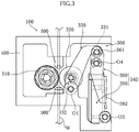
- the feeder 100 is attached to the base end of the welding torch 200. As shown in FIGS. 2 and 3 , the feeder 100 includes a wire feed mechanism 300, a frame 400 for supporting the wire feed mechanism 300, a wire guide 500, and a cover 600.
- the frame 400 is made of a metal, for example.
- the frame 400 has a bottom plate and side plates that are installed upright on this bottom plate, and a given internal space is formed by these plates.
- the wire guide 500 is provided within the frame 400.
- the wire guide 500 guides a wire W, which is supplied via a cable not shown in the diagram. Specifically, a hole for causing the wire W to pass through is formed in the wire guide 500. With this configuration, the wire guide 500 appropriately guides the wire W that has been supplied via the aforementioned cable to the outside of the feeder 100. The wire W that has passed through the feeder 100 is sent to the leading end of the welding torch 200 through the inside of the welding torch 200.
- the wire feed mechanism 300 includes a feed roll 310, a pressure roll 320, a pressure arm 330, a pressure mechanism 340, and a motor 380 (see FIG. 1 ).
- the feed roll 310, pressure roll 320, pressure arm 330, and pressure mechanism 340 are supported by the frame 400, and are accommodated in the internal space of the same frame.
- FIGS. 1 and 2 show a state where the cover 600 is open. With the cover 600 closed, the feed roll 310, pressure roll 320, pressure arm 330, and pressure mechanism 340 are covered by the cover 600.
- the feed roll 310 and pressure roll 320 cooperate with each other to send out the wire W in a desired direction.
- the feed roll 310 is fixed to a rotation shaft 381 of the motor 380.
- the shaft 381 extends parallel to a first direction X1 (see FIG. 1 ), and rotates around an axis parallel to this direction. With the rotation of the shaft 381, the feed roll 310 also rotates around the same axis.
- a groove 312 for guiding the wire W is formed in an outer circumferential face 311 of the feed roll 310.
- the groove 312 is open radially outward relative to the axis of the shaft 381.
- the groove 312 is recessed inward of the outer circumferential face 311 of the feed roll 310.
- the pressure roll 320 is arranged on the side opposite to the feed roll 310 relative to the wire W.
- the pressure roll 320 is rotatably supported by the pressure arm 330.
- the pressure arm 330 is supported by the frame 400 so as to be pivotable around a first shaft 01.
- the pressure roll 320 is configured to rotate around a second shaft 02, which is attached to the pressure arm 330.
- the first shaft 01 and second shaft 02 extend parallel to the first direction X1.
- the outer circumferential face 321 of the pressure roll 320 faces radially outward of the axis of the second shaft 02.
- the outer circumferential face 321 of the pressure roll 320 can approach and move away from the outer circumferential face 311 of the feed roll 310.
- the wire W is fed as a result of the feed roll 310 (and also the pressure roll 320, which serves as a follower roll) rotating with the wire W held between the outer circumferential face 321 of the pressure roll 320 and the groove 312 of the feed roll 310.
- a configuration may be employed in which a groove is formed in the outer circumferential face of the pressure roll 320, and the wire W is held between this groove and the groove 312 of the feed roll 310.
- the rotational direction of the pressure roll 320 is opposite to the rotational direction of the feed roll 310.
- a frictional force is exerted from the feed roll 310 to the wire W, and the wire W is fed.
- the wire W is fed in a downward direction in FIG. 3 .
- the pressure arm 330 is pivotably supported by the frame 400 via the first shaft 01.
- the first shaft 01 is located on the base end side of the pressure arm 330.
- a force-receiving portion 331 is provided in the pressure arm 330 on the leading end side thereof.
- the force-receiving portion 331 is a portion for receiving a force from the later-described pressure mechanism 340 (second structural portion 360) through a pressing force portion 361 of the pressure mechanism 340.
- the pressing force portion 361 has a groove shape.
- the second shaft 02 for supporting the pressure roll 320 is attached to the pressure arm 330.
- the second shaft 02 is located between the first shaft 01 of the pressure arm 330 and the force-receiving portion 331, and is located closer to the first shaft 01 than to the force-receiving portion 331.
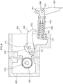
- the pressure mechanism 340 (see FIGS. 3 and 4 ) is for generating a force that acts from the pressure roll 320 toward the feed roll 310 by driving the pressure arm 330.
- the pressure mechanism 340 includes a first structural portion 350 and a second structural portion 360 that is supported by this first structural portion 350.
- the first structural portion 350 includes a case 351, a shaft 352, a nut 353, and a joint 354.
- the shaft 352 is provided within the case 351, and can move in the axial direction (longitudinal direction) of the case 351.
- a locking portion 352a is provided at a base end of the shaft 352, and a locked portion 351a is provided at a base end of the case 351.
- the locking portion 352a has a flange shape that projects perpendicular to the longitudinal direction of the shaft 352.
- a biasing member 370 is fitted onto the shaft 352.
- the biasing member 370 is a coil spring in a state of being compressed relative to its natural length.
- a thread portion is formed on the shaft 352 on the leading end side thereof, and the nut 353 is screwed with this screw portion.
- a main portion of the nut 353 is arranged within the case 351.
- the nut 353 cannot rotate relative to the case 351, but can move in the axial direction.
- the joint 354 is fixed to the leading end of the shaft 352. As is understood from FIGS. 4 , 5 , and so forth, the joint 354 and shaft 352 can be moved in the axial direction by a given stroke. As will be described later (see FIG. 8 ), upon rotating the joint 354 using an operation portion 362 of the second structural portion 360, the shaft 352 rotates therewith.
- One end of the biasing member 370 is in contact with the nut 353, and the other end is in contact with the locked portion 351a of the case 351.
- the nut 353 approaches or move away from the locked portion 351a of the case 351, depending on the rotational direction of the shaft 352.
- the overall length of the biasing member 370 thus changes, and the magnitude of the force exerted by the biasing member 370 can be thus adjusted.
- the case 351 (first structural portion 350) is pivotably supported by the frame 400. Specifically, the case 351 pivots around a third shaft 03.
- the third shaft 03 is located at a base end of the case 351 (first structural portion 350), and extends parallel to the first direction X1.
- the third shaft 03 is located on the side opposite to the feed roll 310 relative to the wire W.
- the third shaft 03 is located farther from the wire W than is the first shaft 01.
- the second structural portion 360 has a generally elongated shape, and has the pressing force portion 361 and the operation portion 362.
- the pressing force portion 361 is provided at one end (first end) of the second structural portion 360, and the operation portion 362 is provided at the other end (second end).
- the pressing force portion 361 is a pin, and is configured to engage with the force-receiving portion 331 of the pressure arm 330 (see FIGS. 4 , 5 , and so forth).
- the second structural portion 360 is pivotably supported by the first structural portion 350. Specifically, the second structural portion 360 pivots around a fourth shaft 04.
- the fourth shaft 04 is located close to the first end of the second structural portion 360, and extends parallel to the first direction X1. In this embodiment, the fourth shaft 04 is located in the joint 354 of the first structural portion 350, i.e. at the leading end of the first structural portion 350.
- the operation portion 362 extends toward the side opposite to the pressing force portion 361 relative to the fourth shaft 04.
- the distance from the third shaft 03 to the fourth shaft 04 is greater than the distance from the fourth shaft 04 to the pressing force portion 361.
- the motor 380 (see FIG. 1 ) is for rotating the feed roll 310.
- the motor 380 is fixed to the base end of the welding torch 200.
- the feed roll 310 is fitted onto a shaft 381 of the motor 380.
- grooves are formed in an outer circumferential face of the shaft 381 and an inner circumferential surface of the feed roll 310, and the same key material 390 is fitted into these grooves.
- the feed roll 310 is thus directly fixed to the shaft 381 of the motor 380.
- the pressure arm 330 is pivotable around the first shaft 01, and the force-receiving portion 331 is provided at the leading end thereof.
- the biasing member 370 compressed coil spring
- the force-receiving portion 331 then receives, from the biasing member 370 (pressure mechanism 340), a force in a direction that is substantially parallel to the direction in which the wire W is fed (in an upward direction in FIG. 4 ).
- the entire pressure mechanism 340 can be arranged close to the wire W. This contributes to a reduction in the size of the wire feed mechanism 300.
- the pressure roll 320 is attached to the second shaft 02, and the second shaft 02 is located closer to the first shaft 01 than to the force-receiving portion 331 of the pressure arm 330. With this configuration, the pressure roll 320 can be appropriately pressed against the feed roll 310 due to the force received by the force-receiving portion 331 from the pressure mechanism 340. This contributes to a reduction in the size of the wire feed mechanism 300.
- FIGS. 5 to 9 show an operation procedure at the time of performing maintenance, such as replacement, of the pressure roll 320 and the feed roll 310.
- the pressure mechanism 340 includes the first structural portion 350 and the second structural portion 360.
- the first structural portion 350 is configured to pivot around the third shaft 03, and the biasing member 370 is provided therewithin.
- the second structural portion 360 is supported so as to be pivotable around the fourth shaft 04 relative to the first structural portion 350, and includes the pressing force portion 361 for applying a force to the force-receiving portion 331 of the pressure arm 330.
- transmission of the biasing force applied by the biasing member 370 can be interrupted by pivoting the second structural portion 360 in the arrow direction in FIG. 5 from the state shown in FIG. 4 .
- the distance from the third shaft 03 to the fourth shaft 04 is greater than the distance from the fourth shaft 04 to the pressing force portion 361.
- the second structural portion 360 includes the operation portion 362 that extends to the side opposite to the pressing force portion 361 relative to the fourth shaft 04. With this configuration, the expansion/contraction stroke of the biasing member 370 provided in the first structural portion 350 can be secured. In addition, a pivot operation force of the operation portion 362 can be amplified to be transmitted to the pressing force portion 361. With this configuration, an operation required to interrupt or transmit the force of the pressure mechanism 340 can be readily performed.
- FIG. 6 shows a state where the operation portion 362 (second structural portion 360) has been further pivoted in the arrow direction from the state shown in FIG. 5 .
- the pressure arm 330 has pivoted around the first shaft 01 in the direction moving away from the wire W (clockwise), and the pressure roll 320 has moved away from the wire W, compared with the state shown in FIG. 5 .
- the pressing force portion 361 is detached from the force-receiving portion 331. Then, by pivoting the first structural portion 350 around the third shaft 03 (clockwise) as shown in FIG.
- the second structural portion 360 can be brought into a state of being completely separate from the pressure arm 330.
- the second structural portion 360 rotates around the axis of the shaft 352
- the second structural portion 360 rotates together with the joint 354, and the nut 353 moves in the axial direction of the shaft 352.
- the overall length (compressed length) of the biasing member 370 changes. For example, if the overall length of the biasing member 370 is shortened (compressed), the elastic restoring force of the biasing member 370 increases. As understood from comparison with the state in FIG.
- the force received by the force-receiving portion 331 can be adjusted by a simple operation to rotate the second structural portion 360.
- a force adjustment mechanism is realized by a configuration that includes the shaft 352, nut 353, and joint 354.
- a scale may be provided in the case 351, for example, in the direction in which the nut 353 moves. This scale facilitates understanding of the amount of movement of the nut 353, and enables accurate adjustment of the pressure force.
- the first structural portion 350 is pivoted around the third shaft 03, and the pressure arm 330 is also pivoted around the first shaft 01.
- the first structural portion 350 and the pressure arm 330 can be thus sufficiently separated from the wire W in a direction that intersects the first direction X1. Accordingly, a large work space for replacing these rolls can be secured.
Landscapes
- Engineering & Computer Science (AREA)
- Physics & Mathematics (AREA)
- Plasma & Fusion (AREA)
- Mechanical Engineering (AREA)
- Wire Processing (AREA)
- Unwinding Of Filamentary Materials (AREA)
Applications Claiming Priority (2)
| Application Number | Priority Date | Filing Date | Title |
|---|---|---|---|
| JP2015004182 | 2015-01-13 | ||
| PCT/JP2016/050199 WO2016114186A1 (ja) | 2015-01-13 | 2016-01-06 | ワイヤ送給機構 |
Publications (3)
| Publication Number | Publication Date |
|---|---|
| EP3246123A1 true EP3246123A1 (de) | 2017-11-22 |
| EP3246123A4 EP3246123A4 (de) | 2018-10-03 |
| EP3246123B1 EP3246123B1 (de) | 2020-10-21 |
Family
ID=56405733
Family Applications (1)
| Application Number | Title | Priority Date | Filing Date |
|---|---|---|---|
| EP16737257.2A Active EP3246123B1 (de) | 2015-01-13 | 2016-01-06 | Drahtvorschubmechanismus |
Country Status (6)
| Country | Link |
|---|---|
| US (1) | US10668552B2 (de) |
| EP (1) | EP3246123B1 (de) |
| JP (1) | JP6668585B2 (de) |
| KR (1) | KR102315757B1 (de) |
| CN (1) | CN107107243B (de) |
| WO (1) | WO2016114186A1 (de) |
Cited By (1)
| Publication number | Priority date | Publication date | Assignee | Title |
|---|---|---|---|---|
| WO2022128891A1 (en) * | 2020-12-17 | 2022-06-23 | Fremco A/S | Cable installation apparatus comprising replaceable drive device |
Families Citing this family (8)
| Publication number | Priority date | Publication date | Assignee | Title |
|---|---|---|---|---|
| JP6973891B2 (ja) * | 2018-04-18 | 2021-12-01 | 株式会社ダイヘン | ワイヤ送給装置 |
| JP7014487B2 (ja) * | 2018-04-23 | 2022-02-01 | 株式会社ダイヘン | ワイヤ送給装置 |
| JP6516275B1 (ja) * | 2018-07-04 | 2019-05-22 | 株式会社カネダ技研 | 綴じ具 |
| CN109570702B (zh) * | 2018-12-10 | 2020-09-29 | 欧地希机电(青岛)有限公司 | 一种气压式退丝防护机构及送丝机 |
| US11738403B2 (en) * | 2020-01-27 | 2023-08-29 | The Esab Group Inc. | Push pull torch |
| CN112340527A (zh) * | 2020-10-28 | 2021-02-09 | 国网山东省电力公司单县供电公司 | 一种用于电力施工的出线管理装置 |
| JP7382087B2 (ja) * | 2021-05-28 | 2023-11-16 | エンド ロボティクス カンパニー リミテッド | 管状部材移動装置 |
| CN119347121B (zh) * | 2024-12-20 | 2025-04-11 | 洛阳航辉新材料有限公司 | 一种钛合金壳体组合激光焊接装置 |
Family Cites Families (15)
| Publication number | Priority date | Publication date | Assignee | Title |
|---|---|---|---|---|
| JPS58119971A (ja) | 1982-01-11 | 1983-07-16 | Hitachi Ltd | 貫流水車 |
| JPS595502Y2 (ja) * | 1982-02-10 | 1984-02-18 | 大阪電気株式会社 | ワイヤ送給装置 |
| JP2506892Y2 (ja) * | 1991-05-24 | 1996-08-14 | 日本鋼管株式会社 | 溶接ワイヤ―送給装置 |
| JP2576544Y2 (ja) * | 1992-09-16 | 1998-07-16 | 株式会社ダイヘン | 溶接ワイヤ送給装置 |
| JP2937861B2 (ja) * | 1996-04-16 | 1999-08-23 | 昭三郎 牧野 | 糸状物の走行に追従する回転体装置 |
| JPH10324458A (ja) * | 1997-05-27 | 1998-12-08 | Babcock Hitachi Kk | 溶接ワイヤ送給装置 |
| CN2365001Y (zh) * | 1999-02-08 | 2000-02-23 | 时代集团公司 | 气保焊送丝机 |
| JP2001287033A (ja) * | 2000-04-03 | 2001-10-16 | Fanuc Ltd | ワイヤ供給装置 |
| US7026574B2 (en) * | 2003-07-22 | 2006-04-11 | Lincoln Global, Inc. | Wire gripper for a drive unit of a wire feeder |
| AT500654B1 (de) * | 2004-07-09 | 2007-01-15 | Fronius Int Gmbh | Einrichtung zum fördern eines schweissdrahts |
| JP5392750B2 (ja) | 2008-10-22 | 2014-01-22 | 株式会社ダイヘン | 溶接ワイヤ送給機及び溶接装置 |
| CN201881037U (zh) * | 2010-10-15 | 2011-06-29 | 北京宏孚瑞达科技有限公司 | 便携式送丝机构 |
| CN102075030B (zh) * | 2010-12-06 | 2012-10-24 | 郑美波 | 蜗轮蜗杆减速型送丝电机设备及其送丝装置和焊接系统 |
| US9162313B2 (en) * | 2010-12-23 | 2015-10-20 | Lincoln Global, Inc. | Wire feeder wire drive design |
| CN202861595U (zh) * | 2012-10-08 | 2013-04-10 | 梁添贵 | 一种焊接机送丝机构 |
-
2016
- 2016-01-06 US US15/541,818 patent/US10668552B2/en active Active
- 2016-01-06 EP EP16737257.2A patent/EP3246123B1/de active Active
- 2016-01-06 KR KR1020177018587A patent/KR102315757B1/ko active Active
- 2016-01-06 WO PCT/JP2016/050199 patent/WO2016114186A1/ja not_active Ceased
- 2016-01-06 JP JP2016569315A patent/JP6668585B2/ja active Active
- 2016-01-06 CN CN201680004769.8A patent/CN107107243B/zh active Active
Cited By (1)
| Publication number | Priority date | Publication date | Assignee | Title |
|---|---|---|---|---|
| WO2022128891A1 (en) * | 2020-12-17 | 2022-06-23 | Fremco A/S | Cable installation apparatus comprising replaceable drive device |
Also Published As
| Publication number | Publication date |
|---|---|
| KR20170102258A (ko) | 2017-09-08 |
| US10668552B2 (en) | 2020-06-02 |
| US20180001413A1 (en) | 2018-01-04 |
| WO2016114186A1 (ja) | 2016-07-21 |
| KR102315757B1 (ko) | 2021-10-20 |
| EP3246123A4 (de) | 2018-10-03 |
| CN107107243A (zh) | 2017-08-29 |
| CN107107243B (zh) | 2019-11-01 |
| JP6668585B2 (ja) | 2020-03-18 |
| EP3246123B1 (de) | 2020-10-21 |
| JPWO2016114186A1 (ja) | 2017-10-19 |
Similar Documents
| Publication | Publication Date | Title |
|---|---|---|
| US10668552B2 (en) | Wire feed mechanism | |
| EP2478987B1 (de) | System und verfahren zur einstellung des drahtelektrodenantriebsdruckes | |
| US10112252B2 (en) | Wire feeder tensioner with definitive settings | |
| KR101641442B1 (ko) | 전동식 드릴을 사용한 직선 왕복 운동 장치 | |
| CN101700598B (zh) | 检测焊丝传送速度的设备 | |
| US20130306612A1 (en) | Adjustable clamping mechanism of a weld head with quick release insert | |
| JP2010284705A (ja) | 接合機へのナット供給装置 | |
| WO2012082786A1 (en) | Welding wire feeder with pushbutton wire guide holder and alignment tongue method using a welding wire feeder having such alignment tongue | |
| EP2651587A1 (de) | Schweissdrahtförderer mit druckknopf-drahtführungshalter und ausrichtungszungenverfahren mit einem schweissdrahtförderer mit einer derartigen ausrichtungszunge | |
| EP3037190B1 (de) | Greifvorrichtung für Befestigungselemente | |
| WO2021114096A1 (zh) | 焊接设备及其送丝装置 | |
| JP2010214412A (ja) | 消耗電極ガスシールドアーク溶接トーチ | |
| JP6874944B2 (ja) | ワイヤ送給装置 | |
| EP2177320A1 (de) | Irreversible Kniehebelantriebsvorrichtung | |
| EP4610181A1 (de) | Applikator für bandmaterial und computerprogramm | |
| US332889A (en) | Wire-feeding machine | |
| JP6267891B2 (ja) | 長尺物の把持装置、及び長尺物の把持方法 | |
| JP2008036747A (ja) | 工作機械の主軸 | |
| JPH02187274A (ja) | スタッド溶接装置 | |
| JP2003311413A (ja) | 溶接ワイヤ送給ユニット | |
| US20240396278A1 (en) | Pneumatic crimping tool | |
| JP2015131333A (ja) | ワイヤガイド、送給装置、アーク処理システム | |
| US2695148A (en) | Adjustable support for welding apparatus | |
| JP5162349B2 (ja) | 抵抗溶接ガン | |
| JPS5932471Y2 (ja) | 溶接装置 |
Legal Events
| Date | Code | Title | Description |
|---|---|---|---|
| STAA | Information on the status of an ep patent application or granted ep patent |
Free format text: STATUS: THE INTERNATIONAL PUBLICATION HAS BEEN MADE |
|
| PUAI | Public reference made under article 153(3) epc to a published international application that has entered the european phase |
Free format text: ORIGINAL CODE: 0009012 |
|
| STAA | Information on the status of an ep patent application or granted ep patent |
Free format text: STATUS: REQUEST FOR EXAMINATION WAS MADE |
|
| 17P | Request for examination filed |
Effective date: 20170706 |
|
| AK | Designated contracting states |
Kind code of ref document: A1 Designated state(s): AL AT BE BG CH CY CZ DE DK EE ES FI FR GB GR HR HU IE IS IT LI LT LU LV MC MK MT NL NO PL PT RO RS SE SI SK SM TR |
|
| AX | Request for extension of the european patent |
Extension state: BA ME |
|
| DAV | Request for validation of the european patent (deleted) | ||
| DAX | Request for extension of the european patent (deleted) | ||
| A4 | Supplementary search report drawn up and despatched |
Effective date: 20180905 |
|
| RIC1 | Information provided on ipc code assigned before grant |
Ipc: B23K 9/173 20060101ALI20180830BHEP Ipc: B23K 9/133 20060101AFI20180830BHEP Ipc: B65H 51/02 20060101ALI20180830BHEP |
|
| STAA | Information on the status of an ep patent application or granted ep patent |
Free format text: STATUS: EXAMINATION IS IN PROGRESS |
|
| 17Q | First examination report despatched |
Effective date: 20190809 |
|
| GRAP | Despatch of communication of intention to grant a patent |
Free format text: ORIGINAL CODE: EPIDOSNIGR1 |
|
| STAA | Information on the status of an ep patent application or granted ep patent |
Free format text: STATUS: GRANT OF PATENT IS INTENDED |
|
| INTG | Intention to grant announced |
Effective date: 20200507 |
|
| GRAS | Grant fee paid |
Free format text: ORIGINAL CODE: EPIDOSNIGR3 |
|
| GRAA | (expected) grant |
Free format text: ORIGINAL CODE: 0009210 |
|
| STAA | Information on the status of an ep patent application or granted ep patent |
Free format text: STATUS: THE PATENT HAS BEEN GRANTED |
|
| AK | Designated contracting states |
Kind code of ref document: B1 Designated state(s): AL AT BE BG CH CY CZ DE DK EE ES FI FR GB GR HR HU IE IS IT LI LT LU LV MC MK MT NL NO PL PT RO RS SE SI SK SM TR |
|
| REG | Reference to a national code |
Ref country code: GB Ref legal event code: FG4D |
|
| REG | Reference to a national code |
Ref country code: CH Ref legal event code: EP |
|
| REG | Reference to a national code |
Ref country code: IE Ref legal event code: FG4D |
|
| REG | Reference to a national code |
Ref country code: DE Ref legal event code: R096 Ref document number: 602016046228 Country of ref document: DE |
|
| REG | Reference to a national code |
Ref country code: AT Ref legal event code: REF Ref document number: 1325339 Country of ref document: AT Kind code of ref document: T Effective date: 20201115 |
|
| REG | Reference to a national code |
Ref country code: NL Ref legal event code: MP Effective date: 20201021 |
|
| PG25 | Lapsed in a contracting state [announced via postgrant information from national office to epo] |
Ref country code: NO Free format text: LAPSE BECAUSE OF FAILURE TO SUBMIT A TRANSLATION OF THE DESCRIPTION OR TO PAY THE FEE WITHIN THE PRESCRIBED TIME-LIMIT Effective date: 20210121 Ref country code: NL Free format text: LAPSE BECAUSE OF FAILURE TO SUBMIT A TRANSLATION OF THE DESCRIPTION OR TO PAY THE FEE WITHIN THE PRESCRIBED TIME-LIMIT Effective date: 20201021 Ref country code: PT Free format text: LAPSE BECAUSE OF FAILURE TO SUBMIT A TRANSLATION OF THE DESCRIPTION OR TO PAY THE FEE WITHIN THE PRESCRIBED TIME-LIMIT Effective date: 20210222 Ref country code: RS Free format text: LAPSE BECAUSE OF FAILURE TO SUBMIT A TRANSLATION OF THE DESCRIPTION OR TO PAY THE FEE WITHIN THE PRESCRIBED TIME-LIMIT Effective date: 20201021 Ref country code: FI Free format text: LAPSE BECAUSE OF FAILURE TO SUBMIT A TRANSLATION OF THE DESCRIPTION OR TO PAY THE FEE WITHIN THE PRESCRIBED TIME-LIMIT Effective date: 20201021 Ref country code: GR Free format text: LAPSE BECAUSE OF FAILURE TO SUBMIT A TRANSLATION OF THE DESCRIPTION OR TO PAY THE FEE WITHIN THE PRESCRIBED TIME-LIMIT Effective date: 20210122 |
|
| REG | Reference to a national code |
Ref country code: AT Ref legal event code: UEP Ref document number: 1325339 Country of ref document: AT Kind code of ref document: T Effective date: 20201021 |
|
| REG | Reference to a national code |
Ref country code: LT Ref legal event code: MG4D |
|
| PG25 | Lapsed in a contracting state [announced via postgrant information from national office to epo] |
Ref country code: SE Free format text: LAPSE BECAUSE OF FAILURE TO SUBMIT A TRANSLATION OF THE DESCRIPTION OR TO PAY THE FEE WITHIN THE PRESCRIBED TIME-LIMIT Effective date: 20201021 Ref country code: ES Free format text: LAPSE BECAUSE OF FAILURE TO SUBMIT A TRANSLATION OF THE DESCRIPTION OR TO PAY THE FEE WITHIN THE PRESCRIBED TIME-LIMIT Effective date: 20201021 Ref country code: BG Free format text: LAPSE BECAUSE OF FAILURE TO SUBMIT A TRANSLATION OF THE DESCRIPTION OR TO PAY THE FEE WITHIN THE PRESCRIBED TIME-LIMIT Effective date: 20210121 Ref country code: LV Free format text: LAPSE BECAUSE OF FAILURE TO SUBMIT A TRANSLATION OF THE DESCRIPTION OR TO PAY THE FEE WITHIN THE PRESCRIBED TIME-LIMIT Effective date: 20201021 Ref country code: PL Free format text: LAPSE BECAUSE OF FAILURE TO SUBMIT A TRANSLATION OF THE DESCRIPTION OR TO PAY THE FEE WITHIN THE PRESCRIBED TIME-LIMIT Effective date: 20201021 Ref country code: IS Free format text: LAPSE BECAUSE OF FAILURE TO SUBMIT A TRANSLATION OF THE DESCRIPTION OR TO PAY THE FEE WITHIN THE PRESCRIBED TIME-LIMIT Effective date: 20210221 |
|
| PG25 | Lapsed in a contracting state [announced via postgrant information from national office to epo] |
Ref country code: HR Free format text: LAPSE BECAUSE OF FAILURE TO SUBMIT A TRANSLATION OF THE DESCRIPTION OR TO PAY THE FEE WITHIN THE PRESCRIBED TIME-LIMIT Effective date: 20201021 |
|
| REG | Reference to a national code |
Ref country code: DE Ref legal event code: R097 Ref document number: 602016046228 Country of ref document: DE |
|
| PG25 | Lapsed in a contracting state [announced via postgrant information from national office to epo] |
Ref country code: RO Free format text: LAPSE BECAUSE OF FAILURE TO SUBMIT A TRANSLATION OF THE DESCRIPTION OR TO PAY THE FEE WITHIN THE PRESCRIBED TIME-LIMIT Effective date: 20201021 Ref country code: SK Free format text: LAPSE BECAUSE OF FAILURE TO SUBMIT A TRANSLATION OF THE DESCRIPTION OR TO PAY THE FEE WITHIN THE PRESCRIBED TIME-LIMIT Effective date: 20201021 Ref country code: SM Free format text: LAPSE BECAUSE OF FAILURE TO SUBMIT A TRANSLATION OF THE DESCRIPTION OR TO PAY THE FEE WITHIN THE PRESCRIBED TIME-LIMIT Effective date: 20201021 Ref country code: LT Free format text: LAPSE BECAUSE OF FAILURE TO SUBMIT A TRANSLATION OF THE DESCRIPTION OR TO PAY THE FEE WITHIN THE PRESCRIBED TIME-LIMIT Effective date: 20201021 Ref country code: EE Free format text: LAPSE BECAUSE OF FAILURE TO SUBMIT A TRANSLATION OF THE DESCRIPTION OR TO PAY THE FEE WITHIN THE PRESCRIBED TIME-LIMIT Effective date: 20201021 Ref country code: CZ Free format text: LAPSE BECAUSE OF FAILURE TO SUBMIT A TRANSLATION OF THE DESCRIPTION OR TO PAY THE FEE WITHIN THE PRESCRIBED TIME-LIMIT Effective date: 20201021 |
|
| PLBE | No opposition filed within time limit |
Free format text: ORIGINAL CODE: 0009261 |
|
| STAA | Information on the status of an ep patent application or granted ep patent |
Free format text: STATUS: NO OPPOSITION FILED WITHIN TIME LIMIT |
|
| PG25 | Lapsed in a contracting state [announced via postgrant information from national office to epo] |
Ref country code: DK Free format text: LAPSE BECAUSE OF FAILURE TO SUBMIT A TRANSLATION OF THE DESCRIPTION OR TO PAY THE FEE WITHIN THE PRESCRIBED TIME-LIMIT Effective date: 20201021 Ref country code: MC Free format text: LAPSE BECAUSE OF FAILURE TO SUBMIT A TRANSLATION OF THE DESCRIPTION OR TO PAY THE FEE WITHIN THE PRESCRIBED TIME-LIMIT Effective date: 20201021 |
|
| REG | Reference to a national code |
Ref country code: CH Ref legal event code: PL |
|
| 26N | No opposition filed |
Effective date: 20210722 |
|
| GBPC | Gb: european patent ceased through non-payment of renewal fee |
Effective date: 20210121 |
|
| PG25 | Lapsed in a contracting state [announced via postgrant information from national office to epo] |
Ref country code: LU Free format text: LAPSE BECAUSE OF NON-PAYMENT OF DUE FEES Effective date: 20210106 |
|
| REG | Reference to a national code |
Ref country code: BE Ref legal event code: MM Effective date: 20210131 |
|
| PG25 | Lapsed in a contracting state [announced via postgrant information from national office to epo] |
Ref country code: AL Free format text: LAPSE BECAUSE OF FAILURE TO SUBMIT A TRANSLATION OF THE DESCRIPTION OR TO PAY THE FEE WITHIN THE PRESCRIBED TIME-LIMIT Effective date: 20201021 Ref country code: IT Free format text: LAPSE BECAUSE OF FAILURE TO SUBMIT A TRANSLATION OF THE DESCRIPTION OR TO PAY THE FEE WITHIN THE PRESCRIBED TIME-LIMIT Effective date: 20201021 Ref country code: FR Free format text: LAPSE BECAUSE OF NON-PAYMENT OF DUE FEES Effective date: 20210131 |
|
| PG25 | Lapsed in a contracting state [announced via postgrant information from national office to epo] |
Ref country code: SI Free format text: LAPSE BECAUSE OF FAILURE TO SUBMIT A TRANSLATION OF THE DESCRIPTION OR TO PAY THE FEE WITHIN THE PRESCRIBED TIME-LIMIT Effective date: 20201021 Ref country code: CH Free format text: LAPSE BECAUSE OF NON-PAYMENT OF DUE FEES Effective date: 20210131 Ref country code: GB Free format text: LAPSE BECAUSE OF NON-PAYMENT OF DUE FEES Effective date: 20210121 Ref country code: LI Free format text: LAPSE BECAUSE OF NON-PAYMENT OF DUE FEES Effective date: 20210131 |
|
| PG25 | Lapsed in a contracting state [announced via postgrant information from national office to epo] |
Ref country code: IE Free format text: LAPSE BECAUSE OF NON-PAYMENT OF DUE FEES Effective date: 20210106 |
|
| PG25 | Lapsed in a contracting state [announced via postgrant information from national office to epo] |
Ref country code: IS Free format text: LAPSE BECAUSE OF FAILURE TO SUBMIT A TRANSLATION OF THE DESCRIPTION OR TO PAY THE FEE WITHIN THE PRESCRIBED TIME-LIMIT Effective date: 20210221 |
|
| PG25 | Lapsed in a contracting state [announced via postgrant information from national office to epo] |
Ref country code: BE Free format text: LAPSE BECAUSE OF NON-PAYMENT OF DUE FEES Effective date: 20210131 |
|
| PG25 | Lapsed in a contracting state [announced via postgrant information from national office to epo] |
Ref country code: HU Free format text: LAPSE BECAUSE OF FAILURE TO SUBMIT A TRANSLATION OF THE DESCRIPTION OR TO PAY THE FEE WITHIN THE PRESCRIBED TIME-LIMIT; INVALID AB INITIO Effective date: 20160106 |
|
| PG25 | Lapsed in a contracting state [announced via postgrant information from national office to epo] |
Ref country code: CY Free format text: LAPSE BECAUSE OF FAILURE TO SUBMIT A TRANSLATION OF THE DESCRIPTION OR TO PAY THE FEE WITHIN THE PRESCRIBED TIME-LIMIT Effective date: 20201021 |
|
| PG25 | Lapsed in a contracting state [announced via postgrant information from national office to epo] |
Ref country code: MK Free format text: LAPSE BECAUSE OF FAILURE TO SUBMIT A TRANSLATION OF THE DESCRIPTION OR TO PAY THE FEE WITHIN THE PRESCRIBED TIME-LIMIT Effective date: 20201021 |
|
| PG25 | Lapsed in a contracting state [announced via postgrant information from national office to epo] |
Ref country code: TR Free format text: LAPSE BECAUSE OF FAILURE TO SUBMIT A TRANSLATION OF THE DESCRIPTION OR TO PAY THE FEE WITHIN THE PRESCRIBED TIME-LIMIT Effective date: 20201021 |
|
| PG25 | Lapsed in a contracting state [announced via postgrant information from national office to epo] |
Ref country code: MT Free format text: LAPSE BECAUSE OF FAILURE TO SUBMIT A TRANSLATION OF THE DESCRIPTION OR TO PAY THE FEE WITHIN THE PRESCRIBED TIME-LIMIT Effective date: 20201021 |
|
| PGFP | Annual fee paid to national office [announced via postgrant information from national office to epo] |
Ref country code: DE Payment date: 20251203 Year of fee payment: 11 |
|
| PGFP | Annual fee paid to national office [announced via postgrant information from national office to epo] |
Ref country code: AT Payment date: 20251230 Year of fee payment: 11 |