EP3246130B2 - Dispositif de presse - Google Patents
Dispositif de presse Download PDFInfo
- Publication number
- EP3246130B2 EP3246130B2 EP16170450.7A EP16170450A EP3246130B2 EP 3246130 B2 EP3246130 B2 EP 3246130B2 EP 16170450 A EP16170450 A EP 16170450A EP 3246130 B2 EP3246130 B2 EP 3246130B2
- Authority
- EP
- European Patent Office
- Prior art keywords
- carrier
- pressing
- material fraction
- pivot axes
- pressing device
- Prior art date
- Legal status (The legal status is an assumption and is not a legal conclusion. Google has not performed a legal analysis and makes no representation as to the accuracy of the status listed.)
- Active
Links
Images


Classifications
-
- B—PERFORMING OPERATIONS; TRANSPORTING
- B25—HAND TOOLS; PORTABLE POWER-DRIVEN TOOLS; MANIPULATORS
- B25B—TOOLS OR BENCH DEVICES NOT OTHERWISE PROVIDED FOR, FOR FASTENING, CONNECTING, DISENGAGING, OR HOLDING
- B25B27/00—Hand tools, specially adapted for fitting together or separating parts or objects whether or not involving some deformation, not otherwise provided for
- B25B27/02—Hand tools, specially adapted for fitting together or separating parts or objects whether or not involving some deformation, not otherwise provided for for connecting objects by press fit or detaching same
- B25B27/10—Hand tools, specially adapted for fitting together or separating parts or objects whether or not involving some deformation, not otherwise provided for for connecting objects by press fit or detaching same inserting fittings into hoses
-
- B—PERFORMING OPERATIONS; TRANSPORTING
- B21—MECHANICAL METAL-WORKING WITHOUT ESSENTIALLY REMOVING MATERIAL; PUNCHING METAL
- B21D—WORKING OR PROCESSING OF SHEET METAL OR METAL TUBES, RODS OR PROFILES WITHOUT ESSENTIALLY REMOVING MATERIAL; PUNCHING METAL
- B21D39/00—Application of procedures in order to connect objects or parts, e.g. coating with sheet metal otherwise than by plating; Tube expanders
- B21D39/04—Application of procedures in order to connect objects or parts, e.g. coating with sheet metal otherwise than by plating; Tube expanders of tubes with tubes; of tubes with rods
- B21D39/048—Application of procedures in order to connect objects or parts, e.g. coating with sheet metal otherwise than by plating; Tube expanders of tubes with tubes; of tubes with rods using presses for radially crimping tubular elements
Definitions
- the present invention relates to a pressing device according to the subject matter of claim 1.
- Pressing devices are known from the prior art.
- the EP 2 340 899 such a pressing device.
- Pressing devices have also become known in which the bolt is held in the press jaw carrier by means of detachable retaining rings.
- a pressing device has become known, with a predetermined breaking point being present, which breaks at a defined location when too great a force occurs.
- a predetermined breaking point is arranged for each bolt opening, which leads to the problem that in the event of failure one or both of the predetermined breaking points tear open, with the pressing lever together with the bearing bolt detaching from the pressing device with great energy
- the DE 10 2004 016110 shows a pressing device according to the preamble of claim 1.
- the invention is based on the object of specifying a pressing device which overcomes the disadvantages of the prior art.
- the pressing device should be safer to use.
- a pressing device comprises at least one carrier element with at least two carrier straps, in each of which at least one carrier opening is arranged, and at least one pressing element with at least one bearing opening for applying a pressing force to a compact, the at least one Pressing element is mounted pivotably about at least one pivot axis on the carrier element.
- One bolt each providing the bearing and the pivot axis extends through the at least one carrier opening and the bearing opening.
- At least one of the support tabs is formed with a larger proportion of material than the other of the support tabs.
- the proportion of material in the carrier element in the area of one carrier tab is greater than the proportion of material in the carrier element in the area of the other carrier tab.
- the proportions of material between the carrier straps are therefore different.
- the carrier straps are therefore designed asymmetrically with regard to the proportion of material.
- the different arrangement of the individual material parts has the advantage that in the event of a failure, only one carrier flap can fail, i.e. tear or break. Simultaneous failure of both support straps can be ruled out. Consequently, the pressing tool can be operated more safely.
- material content means a design that is larger in terms of weight and volume.
- the major portion of material forms an integral part of the carrier flap. This means that the carrier tab with the greater proportion of material is designed differently in terms of its outer shape than the carrier tab without the greater proportion of material.
- the larger proportion of material preferably has the same material properties as the rest of the carrier strap.
- the pressing device comprises two spaced-apart carrier elements with said larger material portions.
- the two carrier elements are arranged relative to one another in such a way that the carrier tab with the larger material portion of the first carrier element lies above the carrier tab without the larger material portion of the second carrier element, and that the carrier tab without the larger proportion of material of the first carrier element lies above the carrier flap with the larger proportion of material of the second carrier element.
- the two carrier elements are not arranged congruently, but oppositely arranged to one another.
- the two support elements are arranged asymmetrically with respect to a plane of symmetry running between the two support elements.
- This preferred embodiment has the advantage that in the event of a failure of one of the carrier straps, the bolt on the other strap is still holding.
- the first support element breaks in the area of the support strap without the larger material portion
- the pressing element continues to hold in the second support element, specifically in the support strap with the larger material portion. This largely prevents the pressing element from flying off.
- each stud extends through a carrier tab which is provided with the larger portion of material and through another carrier tab which is formed without the larger portion of material.
- said larger proportion of material of the carrier element in the region of one carrier strap is asymmetrical with respect to an axis of symmetry with respect to the material proportion of the carrier element region of the other carrier strap.
- the two carrier straps are therefore designed asymmetrically with respect to the axis of symmetry.
- the axis of symmetry preferably runs at right angles to a straight line connecting the two pivot axes, with the axis of symmetry preferably lying centrally between the two pivot axes.
- the straight line runs at right angles to the pivot axes.
- the axis of symmetry can also run at an angle to said straight line.
- the axis of symmetry runs through the two pivot axes, specifically at right angles to them.
- said larger portion of material of one support tab is asymmetrical with respect to a plane of symmetry to the portion of material of the other support tab.
- the plane of symmetry preferably runs at right angles to a straight line connecting the two pivot axes and parallel to the pivot axes, the plane of symmetry preferably lying centrally between the two pivot axes.
- the straight line runs at right angles to the pivot axes.
- the plane of symmetry can also run at an angle to said straight line.
- the plane of symmetry runs through the two pivot axes.
- the plane of symmetry runs at right angles to the two pivot axes through the center of the support bracket without a large proportion of material.
- the larger proportion of material is preferably at least 1% larger. This means that the carrier strap with the larger proportion of material has 1% more material than the carrier strap without the larger proportion of material.
- the larger portion of material is arranged on an outer surface of the carrier strap, which outer surface is preferably oriented essentially parallel to the pivot axes.
- the larger proportion of material is arranged exclusively on an outer surface.
- the larger proportion of material is arranged on an outer surface of the carrier strap and on a front surface of the carrier strap.
- the outer surface is preferably oriented essentially parallel to the pivot axes.
- the front face is preferably substantially perpendicular to the pivot axes.
- the larger portion of material that is arranged in the area of the front surface extends completely or only partially around the carrier opening.
- a predetermined breaking point is arranged in the area of the carrier strap without the larger material portion. With the predetermined breaking point, the breaking behavior can be further optimized.
- two pressing elements are arranged in the form of pressing levers and the support element has two support openings, the bolt extending through one of the support openings and the bearing openings.
- the two pressing levers preferably have at least two pressing jaws for applying the pressing force to the compact and the pivot axes are parallel to one another, with one pressing lever being pivotable about one pivot axis and the other pressing lever being pivotable about the other pivot axis from an initial position into a pressing position such that at the end of the pressing process, the pressing jaws, viewed along the pivot axes, together form a substantially closed circle.
- the pressing device has the form of a pressing sling, with both the pressing element and the carrier element having the shape of a sling part with which a pressing force can be applied to a compact.
- the pressing device has the form of a pressing sling, the pressing element having the shape of a sling part with which a pressing force can be applied to a compact, and the carrier element being an element connecting two sling parts.
- the pressing element is designed in the form of an intermediate jaw with two bearing openings and can in particular be connected to a pressing sling, the carrier element having two carrier openings.
- the bolt extends through one of the support openings and one of the bearing openings.
- the bolt is preferably secured with a securing element which is connected to the end of the bolt.
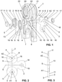
- a pressing device 1 is shown.
- the pressing device shown here is a so-called pressing jaw.
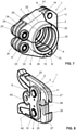
- further pressing devices are shown which have the shape of a press sling ( figure 7 ) and the shape of an intermediate jaw ( figure 8 ) exhibit.
- the same parts bear the same reference numbers.
- the pressing device 1 comprises at least one carrier element 2 and at least one pressing element 7, 8.
- the carrier element 2 has at least two carrier straps 3, 4, in each of which at least one carrier opening 5, 6 is arranged. This means that a carrier opening 5 , 6 is arranged in each of the carrier straps 3 , 4 .
- the pressing element 7 , 8 here includes a bearing opening 14 , 15 in each case, with which the pressing element 7 , 8 can be mounted relative to the carrier elements 2 .
- the pressing element 7, 8 is used to apply a pressing force to a compact.
- the pressing element 7, 8 is mounted on the carrier element 2 such that it can pivot about a pivot axis A1 or A2.
- a bolt 9 , 10 is provided for each pressing element 7 , 8 for storage.
- the bolt 9 , 10 extends through the support opening 5 , 6 of the support elements 2 and through the bearing opening 14 , 15 on the pressing element 7 , 8 .
- the end of the bolt 9, 10 is secured with a securing element 17, with which the bolt is connected.
- At least one of the carrier tabs 3, 4 is formed with a larger proportion of material than the other of the carrier tabs 4, 3.
- the carrier tab 3 is provided with a larger proportion of material 11 in each case.
- the other carrier strap, namely the carrier strap 4 does not have a larger proportion of material 11. This means that the carrier strap 3 is designed asymmetrically to the carrier strap 4 .
- the pressing element 7, 8 is in the figures 1 and 4 designed as a press lever. Two pressing levers are arranged, which are connected to one another with two carrier elements 2 . In the embodiment shown figures 1 and 4 there are two carrier elements 2 spaced apart from one another. Each of the carrier elements 2 has a carrier strap 3 with said larger proportion of material 11 .
- the two pressing levers 7, 8 have at least two pressing jaws 20, 21 for applying the pressing force to the compact.
- the pivot axes A1, A2 lie parallel to one another, with one press lever 7 being pivotable about one pivot axis A1 and the other press lever 8 being pivotable about the other pivot axis A2 from an initial position into a pressing position such that at the end of the pressing process the pressing jaws 7, 8 can be moved along of the pivot axes A1, A2 together form a substantially closed circle.
- the two carrier elements 2 are arranged relative to one another in such a way that the carrier tab 3 with the larger proportion of material 11 of the first carrier element lies above the carrier tab 4 without the larger proportion of material of the second carrier element 2 .
- the carrier tab 3 without the larger material portion of the first carrier element lies above the carrier tab 3 with the larger material portion 11 of the second carrier element 2.
- the carrier tabs are arranged with respect to the larger material portion 11 in such a way that the larger material portions 11 are not are opposite each other.
- the carrier elements 2 are positioned in such a way that each carrier tab 3 with the larger proportion of material 11 is assigned a carrier tab 4 without the larger proportion of material.
- Each of the axes A1, A2 thus extends through a support bracket 3 with the larger proportion of material 11 and through a support bracket 4 without the larger proportion of material.
- each of the carrier elements between the two carrier straps 3, 4 also includes a connecting strap 18 with an opening 19.
- the connecting strap 18 can be connected to the pressing device 1 to form a machine for applying a pressing force to the pressing elements 7, 8.
- a larger proportion of material 11 is arranged on the front surface 13 of the carrier flap 3 .
- the larger portion of material 11 thus extends away from the front face 13 between the two carrier openings 5, 6.
- the larger portion of material 11 preferably extends essentially completely around the carrier opening 5 .
- the extent here is preferably essentially constant around the entire carrier opening.
- the larger portion of material 11 therefore has the shape of a ring which extends around the support opening 5 .
- the larger portion of material 11 can also be designed in such a way that it only partially surrounds the carrier opening 5 .
- the front surface 13 is the surface which faces away from the pressing elements 7,8.
- the two carrier straps 3, 4 are arranged asymmetrically with respect to a plane of symmetry S.
- the plane of symmetry S extends at right angles to a straight line G which connects the two parallel pivot axes A1, A2.
- the plane of symmetry S runs parallel to the pivot axes A1, A2 and is here centrally between the two pivot axes A1, A2. This means that said larger portion of material 11 of one carrier strap 2 is designed asymmetrically with respect to the material portion of the other carrier strap 4 with respect to the plane of symmetry S.
- the carrier strap 3 is designed asymmetrically with respect to the other carrier strap 4 with respect to the plane of symmetry U, which runs at right angles to the two pivot axes A1, A2 through the center of the carrier strap 4 without the larger proportion of material.
- This plane of symmetry bears the reference symbol U.
- the plane of symmetry could also run through the two pivot axes, the plane of symmetry then bearing the reference symbol T.
- the symmetry can also be defined via corresponding symmetry axes.
- a further embodiment of the carrier straps 3, 4 with the larger proportion of material 11 is shown.
- the larger portion of material 11 is arranged on an outer surface 12 of the carrier strap 3 . This is shown by the shaded areas.
- the larger portion of material 11 complements the outer surface 12 to the outside, so to speak.
- the outer surface 12 is oriented here parallel to the pivot axes A1, A2.
- a predetermined breaking point 16 is provided, with a further, larger material portion 28 adjoining said larger material portion and also extending around the other carrier flap 4 without the larger material portion 11.
- a predetermined breaking point 16 can be created by the design of the material portion 28, which only partially extends around the carrier opening. In total, however, the proportion of material in the carrier strap 3 is always greater than in the carrier strap 3.
- two predetermined breaking points 16 are provided.
- the Figures 5 and 6 be said that the support tab 3 is asymmetrical with respect to an axis of symmetry X which is between the two support tabs 3,4.
- the axis of symmetry X extends at right angles to a straight line connecting the two pivot axes A1, A2, with the axis of symmetry X preferably lying centrally between the two pivot axes A1, A2.
- the axis of symmetry can also run at right angles to and through the two pivot axes A1, A2.
- Both the carrier tab 2 according to the Figures 2 and 3 and the carrier flap 2 according to the Figures 5 and 6 here includes an optional predetermined breaking point 16.
- the predetermined breaking point 16 is designed as a notch in the area of the transition to the connecting strap 18. However, this predetermined breaking point 18 can also be dispensed with.
- FIG. 7 shows that the pressing device 1 in the form of a pressing sling has two pressing elements 7, 8 and a carrier element 2 in the form of a sling part with which the pressing force can be applied to a compact.
- Two bolts 9, 10 extend parallel to one another through the two carrier openings 5, 6 or bearing openings 14, 15 of the carrier element 2 or the pressing elements 7, 8, so that the two pivot axes A1, A2 also come to lie parallel to one another.
- the carrier element 2 has two carrier straps 3 , 4 , the carrier strap 3 being formed with the larger proportion of material 11 .
- the carrier strap 4 is formed without the larger proportion of material 11 .
- the pressing elements 7, 8 and the carrier element 2 each have a pressing jaw receptacle 22 with a Recording surface, in which the pressing jaws 20 are incorporated.
- the pressing elements 7, 8 in the form of the loop parts are each connected continuously at one end via the bolts to the carrier element 2, while the other end is an unconnected, free end, between which free ends there is a distance to form a closing point.
- these two free ends are at a minimal distance from one another and the press sling then has an essentially cylindrical cross section.
- the increased material content could also be in the area of the free ends and the bolt connection.
- FIG 8 shows a pressing device 1 having a carrier element 2 with two carrier openings 5, 6 and a pressing element in the form of an intermediate jaw with two bearing openings.
- a bolt 9, 10 extends through one of the support openings 5, 6 and the bearing openings 14, 15 respectively.
- the intermediate jaw is formed with two jaw levers 25 which open into a claw 26 at one end.
- This claw 26 can be inserted into grooves 27 of a press sling such as in figure 7 insert shown and hang in their connecting bolts 23. In the connected position, the claw 26 completely encompasses the connecting bolts 23 of the press sling.
- the jaw levers 25 are then moved towards one another, the free ends of the press sling are also moved towards one another and the compact wrapped around by the press sling is pressed.
- the jaw levers 25 are pivotably mounted on the carrier element 2 via a pivot axis A1, A2 in each case, analogously to the pressing levers, and can thus be pivoted from the initial position, in which the compact has not yet been pressed, into the pressed position in which the compact is pressed.
- the carrier flap 3 of the carrier element 2 is here again provided with a larger proportion of material 11 .
- the carrier flap 4 does not have a large proportion of material.
- Regarding the arrangement of the larger proportion of material is on the above description in connection with the Figures 1 to 6 referred.
Landscapes
- Engineering & Computer Science (AREA)
- Mechanical Engineering (AREA)
- Press Drives And Press Lines (AREA)
- Sawing (AREA)
Claims (11)
- Ensemble de presse (1) comprenantau moins un élément de support (2) qui présente au moins deux pattes de support (3, 4) dans chacune desquelles au moins une ouverture de support (5, 6) est disposée etau moins un élément de presse (7, 8) présentant au moins une ouverture de montage (14, 15) qui applique une force de poussée sur une ébauche de presse, le ou les éléments de presse (7, 8) étant montés sur l'élément de support (2) de manière à pouvoir pivoter autour d'au moins un axe de pivotement (A1, A2),un goujon (9, 10) qui constitue à la fois le palier et l'axe de pivotement (A1, A2) traversant la ou les ouvertures de support (5, 6) et l'ouverture de montage (14, 15),au moins une patte de support (3) étant formée avec une proportion de matière (11) plus grande que l'autre patte de support (4), dans lequel deux éléments de support (2) présentant lesdites plus grandes proportions de matière (11) étant disposés à distance l'un de l'autre, les éléments de support (2) étant disposés l'un par rapport à l'autre de telle sorte que la patte de support (3) qui présente la proportion de matière (11) plus grande du premier élément de support (2) soit située au-dessus de la patte de support (4) qui ne présente pas la proportion de matière plus grande du deuxième élément de support (2) et en ce que la patte de support (4) qui ne présente pas la proportion de matière (11) plus grande du premier élément de support (2) est située au-dessus de la patte de support (3) qui présente la proportion de matière plus grande du deuxième élément de support (2),dans lequel ladite proportion de matière (11) plus grande est disposée sur une surface extérieure (12) de la patte de support (3),dans lequel une proportion de matière (11) plus grande supplémentaire se joint à ladite proportion de matière (11) plus grande et s'étend également autour de l'autre patte de support (4) sans ladite proportion de matière (11) plus grande, etdans lequel un emplacement de rupture préférentielle (16) est réalisé par la formation de la proportion de matière plus grande supplémentaire, qui ne s'étend que partiellement autour de l'ouverture de support (6).
- Ensemble de presse (1) selon l'une quelconque des revendications précédentes, caractérisé en ce qu'au niveau de la patte de support (3), ladite proportion de matière (11) plus grande de l'élément de support (2) est asymétrique par rapport à un axe de symétrie (X, Y) vis-à-vis de la proportion de matière de l'élément de support (2) niveau de l'autre patte de support (4).
- Ensemble de presse (1) selon la revendication 2, caractérisé en ce que l'axe de symétrie (X) s'étend perpendiculairement par rapport à une droite (G) qui relie les deux axes de pivotement (A1, A2), l'axe de symétrie (X) étant de préférence situé au milieu entre les deux axes de pivotement (A1, A2), ou en ce que l'axe de symétrie (Y) s'étend perpendiculairement aux deux axes de pivotement (A1, A2) et à travers ceux-ci.
- Ensemble de presse (1) selon la revendication 1, caractérisé en ce que dans un plan de symétrie (S, T, U), ladite proportion de matière (11) plus grande de la patte de support (3) est asymétrique par rapport à la proportion de matière de l'autre patte de support (4).
- Ensemble de presse (1) selon la revendication 4, caractérisé en ce que le plan de symétrie (S) s'étend perpendiculairement à une droite (G) qui relie les deux axes de pivotement (A1, A2) et parallèlement aux axes de pivotement (A1, A2), le plan de symétrie (S) étant situé de préférence au milieu entre les deux axes de pivotement (A1, A2), ouen ce que le plan de symétrie (T) s'étend à travers les deux axes de pivotement ouen ce que le plan de symétrie (U) s'étend perpendiculairement aux deux axes de pivotement (A1, A2) en passant par le milieu de la patte de support ne présentant pas la plus grande proportion de matière.
- Ensemble de presse (1) selon l'une des revendications précédentes, caractérisé en ce que la proportion de matière (11) plus grande est plus grande d'au moins 1 %.
- Ensemble de presse (1) selon l'une des revendications précédentes, caractérisé en ce que la surface extérieure (12) est orientée essentiellement en parallèle aux axes de pivotement (A1, A2).
- Ensemble de presse selon l'une des revendications 1 à 7, caractérisé en ce que deux éléments de presse (7, 8) sont disposés en forme de leviers de presse et en ce que l'élément de support (2) présente deux ouvertures de support (5, 6), chaque goujon (9, 10) traversant une des ouvertures de support (5, 6) et une des ouvertures de montage (13, 14) .
- Ensemble de presse selon la revendication 8, caractérisé en ce que les deux leviers de presse (7, 8) présentent au moins deux mâchoires de presse qui appliquent la force de poussée sur l'ébauche et en ce que les axes de pivotement (A1, A2) sont parallèles l'un à l'autre, un levier de presse (7) pouvant pivoter autour d'un axe de pivotement (A1) et l'autre levier de presse (8) autour de l'autre axe de pivotement (A2) depuis une position initiale jusque dans une position de poussée de telle sorte qu'à la fin de l'opération de presse, les mâchoires de presse (7, 8) forment ensemble un cercle essentiellement fermé le long des axes de pivotement (A1, A2) .
- Ensemble de presse selon l'une des revendications 1 à 7 qui précèdent, caractérisé en ce quel'ensemble de presse présente la forme d'une boucle de presse, l'élément de presse (7, 8) ainsi que l'élément de support (2) présentant la forme d'une partie de boucle par laquelle une force de poussée peut être appliquée sur une ébauche, oul'ensemble de presse présente la forme d'une boucle de presse, l'élément de presse (7, 8) présentant la forme d'une partie de boucle par laquelle une force de poussée peut être appliquée sur une ébauche, l'élément de support (2) étant un élément qui relie deux parties de boucle ouen ce que l'élément de presse est configuré sous la forme d'une mâchoire intermédiaire présentant deux ouvertures de montage (14, 15) et peut être relié en particulier à une ébauche et en ce que l'élément de support (2) présente deux ouvertures de support (5, 6), le goujon (9, 10) s'étendant à travers l'une des ouvertures de support (5, 6) et l'une des ouvertures de montage (14, 15).
- Ensemble de presse selon l'une des revendications précédentes, caractérisé en ce que le goujon est bloqué par un élément de blocage (17) relié à l'extrémité du goujon.
Priority Applications (1)
| Application Number | Priority Date | Filing Date | Title |
|---|---|---|---|
| EP16170450.7A EP3246130B2 (fr) | 2016-05-19 | 2016-05-19 | Dispositif de presse |
Applications Claiming Priority (1)
| Application Number | Priority Date | Filing Date | Title |
|---|---|---|---|
| EP16170450.7A EP3246130B2 (fr) | 2016-05-19 | 2016-05-19 | Dispositif de presse |
Publications (3)
| Publication Number | Publication Date |
|---|---|
| EP3246130A1 EP3246130A1 (fr) | 2017-11-22 |
| EP3246130B1 EP3246130B1 (fr) | 2019-01-23 |
| EP3246130B2 true EP3246130B2 (fr) | 2022-02-09 |
Family
ID=56081255
Family Applications (1)
| Application Number | Title | Priority Date | Filing Date |
|---|---|---|---|
| EP16170450.7A Active EP3246130B2 (fr) | 2016-05-19 | 2016-05-19 | Dispositif de presse |
Country Status (1)
| Country | Link |
|---|---|
| EP (1) | EP3246130B2 (fr) |
Families Citing this family (1)
| Publication number | Priority date | Publication date | Assignee | Title |
|---|---|---|---|---|
| EP3610988B1 (fr) * | 2018-08-17 | 2021-12-22 | Geberit International AG | Dispositif de pression à fixation à boulon centrée |
Citations (2)
| Publication number | Priority date | Publication date | Assignee | Title |
|---|---|---|---|---|
| WO2006031548A2 (fr) † | 2004-09-09 | 2006-03-23 | Emerson Electric Co. | Ensemble machoire a duree de vie controlee |
| EP2340899A2 (fr) † | 2009-12-15 | 2011-07-06 | REMS-WERK Christian Föll und Söhne GmbH | Outil de presse pour le sertissage radial de pièces usinées et outil doté d'au moins deux éléments d'outil mobiles l'un par rapport à l'autre |
Family Cites Families (2)
| Publication number | Priority date | Publication date | Assignee | Title |
|---|---|---|---|---|
| EP1092487A3 (fr) * | 1999-10-15 | 2004-08-25 | Gustav Klauke GmbH | Dispositif de pressage avec machoires de compression |
| DE102004016110B4 (de) * | 2004-04-01 | 2017-03-30 | Gustav Klauke Gmbh | Presshebel für ein Verpressgerät sowie Verfahren zur Überprüfung der Vollständigkeit einer Verpressung |
-
2016
- 2016-05-19 EP EP16170450.7A patent/EP3246130B2/fr active Active
Patent Citations (2)
| Publication number | Priority date | Publication date | Assignee | Title |
|---|---|---|---|---|
| WO2006031548A2 (fr) † | 2004-09-09 | 2006-03-23 | Emerson Electric Co. | Ensemble machoire a duree de vie controlee |
| EP2340899A2 (fr) † | 2009-12-15 | 2011-07-06 | REMS-WERK Christian Föll und Söhne GmbH | Outil de presse pour le sertissage radial de pièces usinées et outil doté d'au moins deux éléments d'outil mobiles l'un par rapport à l'autre |
Also Published As
| Publication number | Publication date |
|---|---|
| EP3246130A1 (fr) | 2017-11-22 |
| EP3246130B1 (fr) | 2019-01-23 |
Similar Documents
| Publication | Publication Date | Title |
|---|---|---|
| EP2906475B1 (fr) | Capuchon de fermeture, col de contenant, fermeture inviolable et procédé de fabrication d'une fermeture inviolable | |
| DE2709272C2 (de) | Schraubklemme | |
| EP3206898B1 (fr) | Système de liaison pour stabilisateur d'un véhicule | |
| WO2019105702A2 (fr) | Mâchoires de serrage et bords tranchants pour pince à dénuder ainsi que pince à dénuder | |
| DE2854708A1 (de) | Abgabeverschluss | |
| DE1475265A1 (de) | Befestigungsvorrichtung und Verfahren und Einrichtung zu ihrer Herstellung | |
| DE69607462T2 (de) | Selbstsichernde Mutter | |
| WO2019105708A1 (fr) | Pince à dénuder | |
| EP2617622A1 (fr) | Dispositif de soutien vertical d'une barre d'attelage | |
| DE3886887T2 (de) | Gewindereparaturwerkzeug. | |
| DE102017204452A1 (de) | Rotationswerkzeug | |
| EP2340899B1 (fr) | Outil de presse pour le sertissage radial de pièces usinées et outil doté d'au moins deux éléments d'outil mobiles l'un par rapport à l'autre | |
| EP3246130B2 (fr) | Dispositif de presse | |
| EP0551664A1 (fr) | Elément de vissage pour câble avec une douille de vissage et des doigts d'encrage dont la courbe enveloppe en position d'utilisation n'est pas arrondie | |
| EP3580024B1 (fr) | Sécateur | |
| EP3411188B1 (fr) | Tenaille | |
| WO2017202509A1 (fr) | Plaquette de coupe pour un outil de fraisage et outil de fraisage | |
| EP3292931B1 (fr) | Outil, notamment pour l'usinage de pièces à enlèvement de copeaux | |
| EP3095559A1 (fr) | Systeme dynamometrique | |
| DE202007014731U1 (de) | Spann- und Positionierbolzen | |
| EP3231528B1 (fr) | Dispositif de pression comprenant une fixation à boulon | |
| WO2015036209A1 (fr) | Pièce de format et fixations pour pièces de format | |
| DE3341408A1 (de) | Metall-blindniet | |
| DE3347340A1 (de) | Foerderkette | |
| EP3162503B1 (fr) | Dispositif de tension de chaine |
Legal Events
| Date | Code | Title | Description |
|---|---|---|---|
| PUAI | Public reference made under article 153(3) epc to a published international application that has entered the european phase |
Free format text: ORIGINAL CODE: 0009012 |
|
| STAA | Information on the status of an ep patent application or granted ep patent |
Free format text: STATUS: THE APPLICATION HAS BEEN PUBLISHED |
|
| AK | Designated contracting states |
Kind code of ref document: A1 Designated state(s): AL AT BE BG CH CY CZ DE DK EE ES FI FR GB GR HR HU IE IS IT LI LT LU LV MC MK MT NL NO PL PT RO RS SE SI SK SM TR |
|
| AX | Request for extension of the european patent |
Extension state: BA ME |
|
| STAA | Information on the status of an ep patent application or granted ep patent |
Free format text: STATUS: REQUEST FOR EXAMINATION WAS MADE |
|
| 17P | Request for examination filed |
Effective date: 20171219 |
|
| RBV | Designated contracting states (corrected) |
Designated state(s): AL AT BE BG CH CY CZ DE DK EE ES FI FR GB GR HR HU IE IS IT LI LT LU LV MC MK MT NL NO PL PT RO RS SE SI SK SM TR |
|
| GRAP | Despatch of communication of intention to grant a patent |
Free format text: ORIGINAL CODE: EPIDOSNIGR1 |
|
| STAA | Information on the status of an ep patent application or granted ep patent |
Free format text: STATUS: GRANT OF PATENT IS INTENDED |
|
| INTG | Intention to grant announced |
Effective date: 20180803 |
|
| GRAS | Grant fee paid |
Free format text: ORIGINAL CODE: EPIDOSNIGR3 |
|
| GRAA | (expected) grant |
Free format text: ORIGINAL CODE: 0009210 |
|
| STAA | Information on the status of an ep patent application or granted ep patent |
Free format text: STATUS: THE PATENT HAS BEEN GRANTED |
|
| AK | Designated contracting states |
Kind code of ref document: B1 Designated state(s): AL AT BE BG CH CY CZ DE DK EE ES FI FR GB GR HR HU IE IS IT LI LT LU LV MC MK MT NL NO PL PT RO RS SE SI SK SM TR |
|
| REG | Reference to a national code |
Ref country code: GB Ref legal event code: FG4D Free format text: NOT ENGLISH |
|
| REG | Reference to a national code |
Ref country code: CH Ref legal event code: EP |
|
| REG | Reference to a national code |
Ref country code: AT Ref legal event code: REF Ref document number: 1091078 Country of ref document: AT Kind code of ref document: T Effective date: 20190215 |
|
| REG | Reference to a national code |
Ref country code: IE Ref legal event code: FG4D Free format text: LANGUAGE OF EP DOCUMENT: GERMAN |
|
| REG | Reference to a national code |
Ref country code: CH Ref legal event code: NV Representative=s name: ISLER AND PEDRAZZINI AG, CH Ref country code: DE Ref legal event code: R096 Ref document number: 502016003180 Country of ref document: DE |
|
| REG | Reference to a national code |
Ref country code: NL Ref legal event code: MP Effective date: 20190123 |
|
| PG25 | Lapsed in a contracting state [announced via postgrant information from national office to epo] |
Ref country code: NL Free format text: LAPSE BECAUSE OF FAILURE TO SUBMIT A TRANSLATION OF THE DESCRIPTION OR TO PAY THE FEE WITHIN THE PRESCRIBED TIME-LIMIT Effective date: 20190123 |
|
| PG25 | Lapsed in a contracting state [announced via postgrant information from national office to epo] |
Ref country code: PT Free format text: LAPSE BECAUSE OF FAILURE TO SUBMIT A TRANSLATION OF THE DESCRIPTION OR TO PAY THE FEE WITHIN THE PRESCRIBED TIME-LIMIT Effective date: 20190523 Ref country code: NO Free format text: LAPSE BECAUSE OF FAILURE TO SUBMIT A TRANSLATION OF THE DESCRIPTION OR TO PAY THE FEE WITHIN THE PRESCRIBED TIME-LIMIT Effective date: 20190423 Ref country code: FI Free format text: LAPSE BECAUSE OF FAILURE TO SUBMIT A TRANSLATION OF THE DESCRIPTION OR TO PAY THE FEE WITHIN THE PRESCRIBED TIME-LIMIT Effective date: 20190123 Ref country code: SE Free format text: LAPSE BECAUSE OF FAILURE TO SUBMIT A TRANSLATION OF THE DESCRIPTION OR TO PAY THE FEE WITHIN THE PRESCRIBED TIME-LIMIT Effective date: 20190123 Ref country code: ES Free format text: LAPSE BECAUSE OF FAILURE TO SUBMIT A TRANSLATION OF THE DESCRIPTION OR TO PAY THE FEE WITHIN THE PRESCRIBED TIME-LIMIT Effective date: 20190123 Ref country code: PL Free format text: LAPSE BECAUSE OF FAILURE TO SUBMIT A TRANSLATION OF THE DESCRIPTION OR TO PAY THE FEE WITHIN THE PRESCRIBED TIME-LIMIT Effective date: 20190123 Ref country code: LT Free format text: LAPSE BECAUSE OF FAILURE TO SUBMIT A TRANSLATION OF THE DESCRIPTION OR TO PAY THE FEE WITHIN THE PRESCRIBED TIME-LIMIT Effective date: 20190123 |
|
| PG25 | Lapsed in a contracting state [announced via postgrant information from national office to epo] |
Ref country code: LV Free format text: LAPSE BECAUSE OF FAILURE TO SUBMIT A TRANSLATION OF THE DESCRIPTION OR TO PAY THE FEE WITHIN THE PRESCRIBED TIME-LIMIT Effective date: 20190123 Ref country code: RS Free format text: LAPSE BECAUSE OF FAILURE TO SUBMIT A TRANSLATION OF THE DESCRIPTION OR TO PAY THE FEE WITHIN THE PRESCRIBED TIME-LIMIT Effective date: 20190123 Ref country code: HR Free format text: LAPSE BECAUSE OF FAILURE TO SUBMIT A TRANSLATION OF THE DESCRIPTION OR TO PAY THE FEE WITHIN THE PRESCRIBED TIME-LIMIT Effective date: 20190123 Ref country code: IS Free format text: LAPSE BECAUSE OF FAILURE TO SUBMIT A TRANSLATION OF THE DESCRIPTION OR TO PAY THE FEE WITHIN THE PRESCRIBED TIME-LIMIT Effective date: 20190523 Ref country code: BG Free format text: LAPSE BECAUSE OF FAILURE TO SUBMIT A TRANSLATION OF THE DESCRIPTION OR TO PAY THE FEE WITHIN THE PRESCRIBED TIME-LIMIT Effective date: 20190423 Ref country code: GR Free format text: LAPSE BECAUSE OF FAILURE TO SUBMIT A TRANSLATION OF THE DESCRIPTION OR TO PAY THE FEE WITHIN THE PRESCRIBED TIME-LIMIT Effective date: 20190424 |
|
| REG | Reference to a national code |
Ref country code: DE Ref legal event code: R026 Ref document number: 502016003180 Country of ref document: DE |
|
| PG25 | Lapsed in a contracting state [announced via postgrant information from national office to epo] |
Ref country code: DK Free format text: LAPSE BECAUSE OF FAILURE TO SUBMIT A TRANSLATION OF THE DESCRIPTION OR TO PAY THE FEE WITHIN THE PRESCRIBED TIME-LIMIT Effective date: 20190123 Ref country code: EE Free format text: LAPSE BECAUSE OF FAILURE TO SUBMIT A TRANSLATION OF THE DESCRIPTION OR TO PAY THE FEE WITHIN THE PRESCRIBED TIME-LIMIT Effective date: 20190123 Ref country code: AL Free format text: LAPSE BECAUSE OF FAILURE TO SUBMIT A TRANSLATION OF THE DESCRIPTION OR TO PAY THE FEE WITHIN THE PRESCRIBED TIME-LIMIT Effective date: 20190123 Ref country code: CZ Free format text: LAPSE BECAUSE OF FAILURE TO SUBMIT A TRANSLATION OF THE DESCRIPTION OR TO PAY THE FEE WITHIN THE PRESCRIBED TIME-LIMIT Effective date: 20190123 Ref country code: RO Free format text: LAPSE BECAUSE OF FAILURE TO SUBMIT A TRANSLATION OF THE DESCRIPTION OR TO PAY THE FEE WITHIN THE PRESCRIBED TIME-LIMIT Effective date: 20190123 Ref country code: SK Free format text: LAPSE BECAUSE OF FAILURE TO SUBMIT A TRANSLATION OF THE DESCRIPTION OR TO PAY THE FEE WITHIN THE PRESCRIBED TIME-LIMIT Effective date: 20190123 |
|
| PLBI | Opposition filed |
Free format text: ORIGINAL CODE: 0009260 |
|
| PLAX | Notice of opposition and request to file observation + time limit sent |
Free format text: ORIGINAL CODE: EPIDOSNOBS2 |
|
| PG25 | Lapsed in a contracting state [announced via postgrant information from national office to epo] |
Ref country code: SM Free format text: LAPSE BECAUSE OF FAILURE TO SUBMIT A TRANSLATION OF THE DESCRIPTION OR TO PAY THE FEE WITHIN THE PRESCRIBED TIME-LIMIT Effective date: 20190123 |
|
| 26 | Opposition filed |
Opponent name: REMS GMBH & CO KG Effective date: 20191023 |
|
| PG25 | Lapsed in a contracting state [announced via postgrant information from national office to epo] |
Ref country code: MC Free format text: LAPSE BECAUSE OF FAILURE TO SUBMIT A TRANSLATION OF THE DESCRIPTION OR TO PAY THE FEE WITHIN THE PRESCRIBED TIME-LIMIT Effective date: 20190123 |
|
| REG | Reference to a national code |
Ref country code: BE Ref legal event code: MM Effective date: 20190531 |
|
| PG25 | Lapsed in a contracting state [announced via postgrant information from national office to epo] |
Ref country code: SI Free format text: LAPSE BECAUSE OF FAILURE TO SUBMIT A TRANSLATION OF THE DESCRIPTION OR TO PAY THE FEE WITHIN THE PRESCRIBED TIME-LIMIT Effective date: 20190123 Ref country code: LU Free format text: LAPSE BECAUSE OF NON-PAYMENT OF DUE FEES Effective date: 20190519 |
|
| PLBB | Reply of patent proprietor to notice(s) of opposition received |
Free format text: ORIGINAL CODE: EPIDOSNOBS3 |
|
| PG25 | Lapsed in a contracting state [announced via postgrant information from national office to epo] |
Ref country code: TR Free format text: LAPSE BECAUSE OF FAILURE TO SUBMIT A TRANSLATION OF THE DESCRIPTION OR TO PAY THE FEE WITHIN THE PRESCRIBED TIME-LIMIT Effective date: 20190123 |
|
| PG25 | Lapsed in a contracting state [announced via postgrant information from national office to epo] |
Ref country code: IE Free format text: LAPSE BECAUSE OF NON-PAYMENT OF DUE FEES Effective date: 20190519 |
|
| PG25 | Lapsed in a contracting state [announced via postgrant information from national office to epo] |
Ref country code: BE Free format text: LAPSE BECAUSE OF NON-PAYMENT OF DUE FEES Effective date: 20190531 |
|
| PG25 | Lapsed in a contracting state [announced via postgrant information from national office to epo] |
Ref country code: CY Free format text: LAPSE BECAUSE OF FAILURE TO SUBMIT A TRANSLATION OF THE DESCRIPTION OR TO PAY THE FEE WITHIN THE PRESCRIBED TIME-LIMIT Effective date: 20190123 |
|
| PG25 | Lapsed in a contracting state [announced via postgrant information from national office to epo] |
Ref country code: HU Free format text: LAPSE BECAUSE OF FAILURE TO SUBMIT A TRANSLATION OF THE DESCRIPTION OR TO PAY THE FEE WITHIN THE PRESCRIBED TIME-LIMIT; INVALID AB INITIO Effective date: 20160519 Ref country code: MT Free format text: LAPSE BECAUSE OF FAILURE TO SUBMIT A TRANSLATION OF THE DESCRIPTION OR TO PAY THE FEE WITHIN THE PRESCRIBED TIME-LIMIT Effective date: 20190123 |
|
| APAH | Appeal reference modified |
Free format text: ORIGINAL CODE: EPIDOSCREFNO |
|
| APBM | Appeal reference recorded |
Free format text: ORIGINAL CODE: EPIDOSNREFNO |
|
| APBP | Date of receipt of notice of appeal recorded |
Free format text: ORIGINAL CODE: EPIDOSNNOA2O |
|
| APBU | Appeal procedure closed |
Free format text: ORIGINAL CODE: EPIDOSNNOA9O |
|
| PUAH | Patent maintained in amended form |
Free format text: ORIGINAL CODE: 0009272 |
|
| STAA | Information on the status of an ep patent application or granted ep patent |
Free format text: STATUS: PATENT MAINTAINED AS AMENDED |
|
| 27A | Patent maintained in amended form |
Effective date: 20220209 |
|
| AK | Designated contracting states |
Kind code of ref document: B2 Designated state(s): AL AT BE BG CH CY CZ DE DK EE ES FI FR GB GR HR HU IE IS IT LI LT LU LV MC MK MT NL NO PL PT RO RS SE SI SK SM TR |
|
| REG | Reference to a national code |
Ref country code: DE Ref legal event code: R102 Ref document number: 502016003180 Country of ref document: DE |
|
| PG25 | Lapsed in a contracting state [announced via postgrant information from national office to epo] |
Ref country code: MK Free format text: LAPSE BECAUSE OF FAILURE TO SUBMIT A TRANSLATION OF THE DESCRIPTION OR TO PAY THE FEE WITHIN THE PRESCRIBED TIME-LIMIT Effective date: 20190123 |
|
| REG | Reference to a national code |
Ref country code: AT Ref legal event code: MM01 Ref document number: 1091078 Country of ref document: AT Kind code of ref document: T Effective date: 20210519 |
|
| PG25 | Lapsed in a contracting state [announced via postgrant information from national office to epo] |
Ref country code: AT Free format text: LAPSE BECAUSE OF NON-PAYMENT OF DUE FEES Effective date: 20210519 |
|
| P01 | Opt-out of the competence of the unified patent court (upc) registered |
Effective date: 20230516 |
|
| PGFP | Annual fee paid to national office [announced via postgrant information from national office to epo] |
Ref country code: DE Payment date: 20250521 Year of fee payment: 10 |
|
| PGFP | Annual fee paid to national office [announced via postgrant information from national office to epo] |
Ref country code: GB Payment date: 20250521 Year of fee payment: 10 |
|
| PGFP | Annual fee paid to national office [announced via postgrant information from national office to epo] |
Ref country code: IT Payment date: 20250523 Year of fee payment: 10 |
|
| PGFP | Annual fee paid to national office [announced via postgrant information from national office to epo] |
Ref country code: FR Payment date: 20250528 Year of fee payment: 10 |
|
| PGFP | Annual fee paid to national office [announced via postgrant information from national office to epo] |
Ref country code: CH Payment date: 20250601 Year of fee payment: 10 |