EP3246196A1 - Ladepistole und ladeverfahren für elektrisches fahrzeug - Google Patents
Ladepistole und ladeverfahren für elektrisches fahrzeug Download PDFInfo
- Publication number
- EP3246196A1 EP3246196A1 EP16199971.9A EP16199971A EP3246196A1 EP 3246196 A1 EP3246196 A1 EP 3246196A1 EP 16199971 A EP16199971 A EP 16199971A EP 3246196 A1 EP3246196 A1 EP 3246196A1
- Authority
- EP
- European Patent Office
- Prior art keywords
- electric vehicle
- temperature
- charge gun
- level
- charge
- Prior art date
- Legal status (The legal status is an assumption and is not a legal conclusion. Google has not performed a legal analysis and makes no representation as to the accuracy of the status listed.)
- Granted
Links
Images


Classifications
-
- B—PERFORMING OPERATIONS; TRANSPORTING
- B60—VEHICLES IN GENERAL
- B60L—PROPULSION OF ELECTRICALLY-PROPELLED VEHICLES; SUPPLYING ELECTRIC POWER FOR AUXILIARY EQUIPMENT OF ELECTRICALLY-PROPELLED VEHICLES; ELECTRODYNAMIC BRAKE SYSTEMS FOR VEHICLES IN GENERAL; MAGNETIC SUSPENSION OR LEVITATION FOR VEHICLES; MONITORING OPERATING VARIABLES OF ELECTRICALLY-PROPELLED VEHICLES; ELECTRIC SAFETY DEVICES FOR ELECTRICALLY-PROPELLED VEHICLES
- B60L53/00—Methods of charging batteries, specially adapted for electric vehicles; Charging stations or on-board charging equipment therefor; Exchange of energy storage elements in electric vehicles
- B60L53/10—Methods of charging batteries, specially adapted for electric vehicles; Charging stations or on-board charging equipment therefor; Exchange of energy storage elements in electric vehicles characterised by the energy transfer between the charging station and the vehicle
- B60L53/14—Conductive energy transfer
- B60L53/18—Cables specially adapted for charging electric vehicles
-
- B—PERFORMING OPERATIONS; TRANSPORTING
- B60—VEHICLES IN GENERAL
- B60L—PROPULSION OF ELECTRICALLY-PROPELLED VEHICLES; SUPPLYING ELECTRIC POWER FOR AUXILIARY EQUIPMENT OF ELECTRICALLY-PROPELLED VEHICLES; ELECTRODYNAMIC BRAKE SYSTEMS FOR VEHICLES IN GENERAL; MAGNETIC SUSPENSION OR LEVITATION FOR VEHICLES; MONITORING OPERATING VARIABLES OF ELECTRICALLY-PROPELLED VEHICLES; ELECTRIC SAFETY DEVICES FOR ELECTRICALLY-PROPELLED VEHICLES
- B60L3/00—Electric devices on electrically-propelled vehicles for safety purposes; Monitoring operating variables, e.g. speed, deceleration or energy consumption
- B60L3/04—Cutting off the power supply under fault conditions
-
- B—PERFORMING OPERATIONS; TRANSPORTING
- B60—VEHICLES IN GENERAL
- B60L—PROPULSION OF ELECTRICALLY-PROPELLED VEHICLES; SUPPLYING ELECTRIC POWER FOR AUXILIARY EQUIPMENT OF ELECTRICALLY-PROPELLED VEHICLES; ELECTRODYNAMIC BRAKE SYSTEMS FOR VEHICLES IN GENERAL; MAGNETIC SUSPENSION OR LEVITATION FOR VEHICLES; MONITORING OPERATING VARIABLES OF ELECTRICALLY-PROPELLED VEHICLES; ELECTRIC SAFETY DEVICES FOR ELECTRICALLY-PROPELLED VEHICLES
- B60L53/00—Methods of charging batteries, specially adapted for electric vehicles; Charging stations or on-board charging equipment therefor; Exchange of energy storage elements in electric vehicles
- B60L53/10—Methods of charging batteries, specially adapted for electric vehicles; Charging stations or on-board charging equipment therefor; Exchange of energy storage elements in electric vehicles characterised by the energy transfer between the charging station and the vehicle
- B60L53/14—Conductive energy transfer
- B60L53/16—Connectors, e.g. plugs or sockets, specially adapted for charging electric vehicles
-
- B—PERFORMING OPERATIONS; TRANSPORTING
- B60—VEHICLES IN GENERAL
- B60L—PROPULSION OF ELECTRICALLY-PROPELLED VEHICLES; SUPPLYING ELECTRIC POWER FOR AUXILIARY EQUIPMENT OF ELECTRICALLY-PROPELLED VEHICLES; ELECTRODYNAMIC BRAKE SYSTEMS FOR VEHICLES IN GENERAL; MAGNETIC SUSPENSION OR LEVITATION FOR VEHICLES; MONITORING OPERATING VARIABLES OF ELECTRICALLY-PROPELLED VEHICLES; ELECTRIC SAFETY DEVICES FOR ELECTRICALLY-PROPELLED VEHICLES
- B60L53/00—Methods of charging batteries, specially adapted for electric vehicles; Charging stations or on-board charging equipment therefor; Exchange of energy storage elements in electric vehicles
- B60L53/30—Constructional details of charging stations
-
- H—ELECTRICITY
- H02—GENERATION; CONVERSION OR DISTRIBUTION OF ELECTRIC POWER
- H02J—ELECTRIC POWER NETWORKS; CIRCUIT ARRANGEMENTS OR SYSTEMS FOR SUPPLYING OR DISTRIBUTING ELECTRIC POWER; SYSTEMS FOR STORING ELECTRIC ENERGY
- H02J7/00—Circuit arrangements for charging or discharging batteries or for supplying loads from batteries
- H02J7/70—Circuit arrangements for charging or discharging batteries or for supplying loads from batteries characterised by the mechanical construction
- H02J7/751—Circuit arrangements for charging or discharging batteries or for supplying loads from batteries characterised by the mechanical construction concerning the insertion or the connection of the batteries
-
- Y—GENERAL TAGGING OF NEW TECHNOLOGICAL DEVELOPMENTS; GENERAL TAGGING OF CROSS-SECTIONAL TECHNOLOGIES SPANNING OVER SEVERAL SECTIONS OF THE IPC; TECHNICAL SUBJECTS COVERED BY FORMER USPC CROSS-REFERENCE ART COLLECTIONS [XRACs] AND DIGESTS
- Y02—TECHNOLOGIES OR APPLICATIONS FOR MITIGATION OR ADAPTATION AGAINST CLIMATE CHANGE
- Y02T—CLIMATE CHANGE MITIGATION TECHNOLOGIES RELATED TO TRANSPORTATION
- Y02T10/00—Road transport of goods or passengers
- Y02T10/60—Other road transportation technologies with climate change mitigation effect
- Y02T10/70—Energy storage systems for electromobility, e.g. batteries
-
- Y—GENERAL TAGGING OF NEW TECHNOLOGICAL DEVELOPMENTS; GENERAL TAGGING OF CROSS-SECTIONAL TECHNOLOGIES SPANNING OVER SEVERAL SECTIONS OF THE IPC; TECHNICAL SUBJECTS COVERED BY FORMER USPC CROSS-REFERENCE ART COLLECTIONS [XRACs] AND DIGESTS
- Y02—TECHNOLOGIES OR APPLICATIONS FOR MITIGATION OR ADAPTATION AGAINST CLIMATE CHANGE
- Y02T—CLIMATE CHANGE MITIGATION TECHNOLOGIES RELATED TO TRANSPORTATION
- Y02T10/00—Road transport of goods or passengers
- Y02T10/60—Other road transportation technologies with climate change mitigation effect
- Y02T10/7072—Electromobility specific charging systems or methods for batteries, ultracapacitors, supercapacitors or double-layer capacitors
-
- Y—GENERAL TAGGING OF NEW TECHNOLOGICAL DEVELOPMENTS; GENERAL TAGGING OF CROSS-SECTIONAL TECHNOLOGIES SPANNING OVER SEVERAL SECTIONS OF THE IPC; TECHNICAL SUBJECTS COVERED BY FORMER USPC CROSS-REFERENCE ART COLLECTIONS [XRACs] AND DIGESTS
- Y02—TECHNOLOGIES OR APPLICATIONS FOR MITIGATION OR ADAPTATION AGAINST CLIMATE CHANGE
- Y02T—CLIMATE CHANGE MITIGATION TECHNOLOGIES RELATED TO TRANSPORTATION
- Y02T90/00—Enabling technologies or technologies with a potential or indirect contribution to GHG emissions mitigation
- Y02T90/10—Technologies relating to charging of electric vehicles
- Y02T90/12—Electric charging stations
-
- Y—GENERAL TAGGING OF NEW TECHNOLOGICAL DEVELOPMENTS; GENERAL TAGGING OF CROSS-SECTIONAL TECHNOLOGIES SPANNING OVER SEVERAL SECTIONS OF THE IPC; TECHNICAL SUBJECTS COVERED BY FORMER USPC CROSS-REFERENCE ART COLLECTIONS [XRACs] AND DIGESTS
- Y02—TECHNOLOGIES OR APPLICATIONS FOR MITIGATION OR ADAPTATION AGAINST CLIMATE CHANGE
- Y02T—CLIMATE CHANGE MITIGATION TECHNOLOGIES RELATED TO TRANSPORTATION
- Y02T90/00—Enabling technologies or technologies with a potential or indirect contribution to GHG emissions mitigation
- Y02T90/10—Technologies relating to charging of electric vehicles
- Y02T90/14—Plug-in electric vehicles
Definitions
- the present disclosure relates to a charge gun and an electric vehicle supply equipment (EVSE), and in particular, to the charge gun and the electric vehicle supply equipment (EVSE) with over temperature protection.
- EVSE electric vehicle supply equipment
- the charge gun includes at least one charging terminal, a ground terminal, a control pilot terminal and an over temperature detecting circuit.
- the charging terminal is configured to be electrically coupled to an electric vehicle to charge the electric vehicle.
- the ground terminal is electrically coupled to an equipment ground.
- the control pilot terminal is configured to transmit a control pilot signal between the charge gun and the electric vehicle.
- the over-temperature detecting circuit is electrically coupled between the ground terminal and the control pilot terminal.
- the over-temperature detecting circuit includes a temperature sensor and a resistance of temperature sensor changes correspondingly when temperature of the charge gun exceeds a safety limit value.
- the electric vehicle charging method includes: charging, by a charge gun of an electric vehicle supply equipment, an electric vehicle through at least one charging terminal according to a control pilot signal; detecting, by a temperature sensor of the electric vehicle supply equipment, temperature of the charge gun; and changing a resistance of the temperature sensor correspondingly when a temperature of the charge gun exceeds a safety limit value, such that a positive level or a negative level of the control pilot signal is switched from a first level to a second level different from the first level.
- Coupled may also be termed “electrically coupled,” and the term “connected” may be termed “electrically connected.” “Coupled” and “connected” may also be used to indicate that two or more elements cooperate or interact with each other. It will be understood that, although the terms “first,” “second,” etc., may be used herein to describe various elements, these elements should not be limited by these terms. These terms are used to distinguish one element from another. For example, a first element could be termed a second element, and, similarly, a second element could be termed a first element, without departing from the scope of the embodiments.
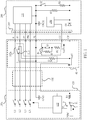
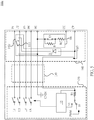
- Fig. 1 is a diagram illustrating charging of an electric vehicle according to some embodiments of the present disclosure.
- a charging device 100a is configured to charge an electric vehicle (EV) 200.
- the charging device 100a may be an Electric Vehicle Supply Equipment (EVSE), which includes a charging module 120, a charging wire 130 and a charge gun 140.
- EVSE Electric Vehicle Supply Equipment
- the charge gun 140 is connected to the charging module 120 through the charging wire 130, and is configured to transmit electricity power through the charging wire 130.
- the charge gun 140 may be configured to charge the electric vehicle 200 when being connected to the electric vehicle 200.
- EVSE Electric Vehicle Supply Equipment
- the charge gun 140 includes multiple terminals corresponding to a socket 210 of the electric vehicle 200, such that the charge gun 140 and the electric vehicle 200 may be electrically coupled to each other.
- the charge gun 140 includes charging terminals P1-P3 and PN, a ground terminal PE, a control pilot terminal CP and a connection confirming terminal CC.
- the charging terminals P1-P3 in the charge gun 140 are configured to be electrically coupled to a power storage system 220 in the electric vehicle 200 through the corresponding terminals on the socket 210 in the electric vehicle 200, thereby charging the electric vehicle 200.
- the power storage system 220 may be an EV onboard charger system.
- the charging device 100a may be an AC type charging device, and the charging terminals P1-P3 are configured to provide three-phase AC power, and the charging terminal PN may be a neutral point of the three-phase electricity system, but the present disclosure is not limited thereto.
- the charging device 100a may also be a DC type charging device, and is configured to provide DC power to the electric vehicle 200 through corresponding charging terminals.
- the ground terminal PE in the charge gun 140 is electrically coupled to an equipment ground GND1 in the charging device 100a through the charging wire 130, and corresponds to the terminal electrically coupled to an EV ground GND2 on the socket 210 in the electric vehicle 200.
- both sides of the charging device 100a and the electric vehicle 200 may have the same reference levels.
- connection confirming terminal CC in the charge gun 140 is configured to be electrically coupled to the electric vehicle 200, and is configured to enable the control circuit in the electric vehicle 200 to detect whether a user is connecting the charge gun 140 to the socket 210 of the electric vehicle 200, or is plugging out the charge gun 140 from the socket 210 of the electric vehicle 200, so as to switch off the electricity path immediately to prevent accidents from happening.
- the control pilot terminal CP in the charge gun 140 is configured to transmit a control pilot signal Vcp1 between the charge gun 140 and the electric vehicle 200, such that the control circuit in the charging device 100a and the electric vehicle 200 may detect charging information such as whether the charge gun 140 is connected to or detached from the electric vehicle 200, whether the charging preparation is completed, the amount of the charging current required by the electric vehicle 200, and whether the charging process is completed, according to a voltage level and a duty cycle of the control pilot signal Vcp1, in which specific operations will be explained in details in the following paragraphs.
- the charging module 120 in the charging device 100a includes a control circuit 122 electrically coupled to the control pilot terminal CP through the charging wire 130, and is configured to control the charge gun 140 to charge the electric vehicle 200 through the charging terminals P1-P3 and PN according to the control pilot signal Vcp1.
- the switching unit S1 in the charging module 120 is configured to be switched to the node a, such that the first terminal of the resistance unit R1 receives a predetermined voltage V1 of a first level (e.g., about 12 Volts). Meanwhile, the control pilot signal Vcp1 received by the control circuit 122 from the second terminal of the resistance unit R1 is also at the first level.
- a first level e.g., about 12 Volts
- the resistance unit R1 in the charging module 120 and the diode unit D1 and the resistance unit R3 in the electric vehicle 200 are electrically coupled in series, and form an electricity path such that the voltage level of the control pilot signal Vcp1 is voltage divided to a second level (e.g., about 9 volts) that is lower than the first level.
- control circuit 122 detects changes of the control pilot signal Vcp1, and controls the switching unit S1 to be switched to the node b, such that the first terminal of the resistance unit R1 receives a pulse width modulation signal PWM (e.g., a switching signal having a high level of about 12 Volts and a low level of about -12 Volts).
- PWM pulse width modulation signal
- the control pilot signal Vcp1 is configured to be switching between the second level (e.g., about 9 volts) and the low level (e.g., about -12 volts).
- control circuit 240 in the electric vehicle 200 may be configured to check a state of the charging device 100a by detecting the control pilot signal Vcp1, and to perform charging preparation.
- the control circuit 240 may output a corresponding signal to turn on the switching unit S2, such that the resistance unit R2 and the resistance unit R3 are electrically coupled in parallel.
- the control pilot signal Vcp1 will switch between a third level (e.g., about 6 volts) that is lower than the second level and the low level (e.g., about -12 volts) due to the electricity path formed by the resistance unit R2.
- control circuit 122 may control the power line L1-L3 and LN of the charging device 100a to start supplying power correspondingly after detecting the change of the control pilot signal Vcp1, and to charge the power storage system 220 in the electric vehicle 200 through the charging terminal P1-P3 and PN of the charge gun 140.
- control circuit 240 may be used to correspondingly control the on and off of the switching unit S2, and the control circuit 122 may be used to correspondingly control the switching of the switching unit S1, thereby enabling the control pilot signal Vcp1 to have specific levels to notify the charging device 100a to stop supplying power, in which such specific operations may be achieved by executing the aforementioned operations reversely, and thus further explanation is omitted for the sake of brevity.
- the charge gun 140 further includes an over temperature detecting circuit 142a and a connection confirming circuit 144, in addition to the multiple terminals.
- the over temperature detecting circuit 142a is electrically coupled between the ground terminal PE (i.e., the equipment ground GND1) and the control pilot terminal CP.
- connection confirming circuit 144 is electrically coupled between the connection confirming terminal CC and the ground terminal PE, and is configured to output a connection confirming signal Vcc to the control circuit 240 in the electric vehicle 200, so as to control the charging of the electric vehicle 200 performed by the charge gun 140.
- the connection confirming circuit 144 includes resistance units R4 and RC, and a switching unit S3.
- the resistance unit R4 and the switching unit S3 are electrically coupled in parallel, and then are electrically coupled to the resistance unit RC in series.
- the switching unit S3 may be a normally closed switch which is conductive and bypasses the resistance unit R4 terminal at normal time.
- the control circuit 240 may perform corresponding control to stop the power transmission between the charging device 100a and the electric vehicle 200 when detecting the change of the voltage level of the connection confirming signal Vcc, thereby ensuring the safety of the user and the charging system.
- the over temperature detecting circuit 142a includes a temperature sensor ST1, and a resistance of the temperature sensor ST1 changes correspondingly when the temperature sensor ST1 detects that a temperature of the charge gun 140 exceeds a safety limit value.
- the temperature sensor ST1 may be realized by various circuit elements such as temperature switches, thermistors, temperature coefficient resettable fuses, etc.
- the temperature sensor ST1 may include a temperature switch. The temperature switch is turned off when the temperature of the charge gun 140 is lower than the safety limit value. On the other hand, the temperature switch is turned on when the temperature of the charge gun 140 exceeds the safety limit value. Accordingly, the over temperature detecting circuit 142a may change the overall resistance value of the over temperature detecting circuit 142a by changing the resistance of the temperature sensor ST1 to different states, and then may change the waveform characteristics of the control pilot signal Vcp1.
- the over temperature detecting circuit 142a includes a resistance unit RT1 electrically coupled to the temperature sensor ST1 in series.
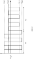
- Fig. 2 is a waveform diagram illustrating the control pilot signal Vcp1 shown in Fig. 1 according to some embodiments of the present disclosure.
- the temperature switch is turned off when the temperature of the charge gun 140 is lower than the safety limit value, and thus the control pilot signal Vcp1 switches between the high level VH1 and the low level VL1.
- the high level VH1 may be about 6 volts and the low level VL1 may be about -12 volts.
- the control pilot signal Vcp1 switches between the high level VH2 and the low level VL2 after being voltage divided at this time, as shown in the period T2 in Fig. 2 .
- the high level VH2 is lower than the high level VH1, and the low level VL2 is higher than the low level VL1.
- the high level VH2 may be about 2 volts, and the low level VL2 may be about -10 volts, but the present disclosure is not limited thereto.
- One skilled in the art may arrange the resistance value of the resistance unit R1-R3 and the resistance unit RT1 based on actual needs, so as to adjust the voltage waveform of the control pilot signal Vcp1.
- the temperature sensor ST1 may be implemented by various circuit elements such as thermistors, such that the over temperature detecting circuit 142a has different resistance values under a normal operation and an over temperature operation, and then the waveform characteristics of the control pilot signal Vcp1 can be further realized, as illustrated in Fig. 2 .
- the control circuit 122 in the charging module 120 may determine whether the temperature of the charge gun 140 exceeds the safety limit value by detecting the control pilot signal Vcp1, and performs protection operations accordingly. For example, in some embodiments, the control circuit 122 controls the charging module 120 to lower the output to the electric vehicle 200 when the control circuit 122 determines that over temperature occurs in the charge gun 140. In some other embodiments, the control circuit 122 may also control the charging module 120 to stop charging the electric vehicle 200, or to output a warning signal. For example, the control circuit 122 may collaborate with an audio module, a lighting module, or a display module etc. to warn the user with sound or light that charging is abnormal.
- the control circuit 240 of the electric vehicle 200 may also receive the abnormal temperature information by the control pilot signal Vcp1 and stop the charging operations from the electric vehicle 200 side to protect the electric vehicle 200.
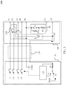
- Fig. 3 is a diagram illustrating a charging device 100b according to some other embodiments of the present disclosure.
- the over temperature detecting circuit 142b may include the temperature sensor ST1 and a diode unit DT1.
- the diode unit DT1 is electrically coupled to the temperature sensor ST1 in series.
- the anode terminal of the diode unit DT1 is electrically coupled to the temperature sensor ST1
- the cathode terminal of the diode unit DT1 is electrically coupled to the control pilot terminal CP.
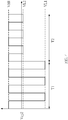
- Fig. 4 is a waveform diagram illustrating a control pilot signal Vcp2 shown in Fig. 3 according to some embodiments of the present disclosure.
- the temperature sensor ST1 in a period T1, the temperature sensor ST1 is turned off when the temperature of the charge gun 140 is lower than the safety limit value, and thus the control pilot signal Vcp2 switches between the high level VH1 and the low level VL1.
- the high level VH1 may be about 6 volts and the low level VL1 may be about -12 volts.
- the temperature sensor ST1 When the temperature of the charge gun 140 exceeds the safety limit value, the temperature sensor ST1 is turned on to enable the diode unit DT1 to be coupled between the control pilot terminal CP and the equipment ground GND1. Thus, in the forward period, the diode unit DT1 is off and the level of the control pilot signal Vcp2 remains unchanged. On the other hand, in the reversed period, the diode unit DT1 is on and the low level of the control pilot signal Vcp2 is clamped at the low level VL2, as shown in the period T2 in Fig. 2 .
- the high level VH1 may be about 6 volts
- the low level VL1 may be about -12 volts
- the low level VL2 may be about -0.7 volts, but the present disclosure is not limited thereto.
- the over temperature detecting circuit 142b may further include a resistance unit electrically coupled to the diode unit DT1 in series to further adjust the voltage level of the control pilot signal Vcp2, in which the operations are discussed in the aforementioned embodiments, and thus are omitted herein for the sake of brevity.
- Fig. 5 is a diagram illustrating a charging device 100c according to some other embodiments of the present disclosure. With respect to Fig. 1 and Fig. 3 , like elements in FIG. 5 are designated with the same reference numbers for ease of understanding.
- the over temperature detecting circuit 142b also includes the temperature sensor ST1 and the diode unit DT1, but the cathode terminal of the diode unit DT1 is electrically coupled to the temperature sensor ST1, and the anode terminal of the diode unit DT1 is electrically coupled to the control pilot terminal CP.
- Fig. 6 is a waveform diagram illustrating a control pilot signal Vcp3 shown in Fig. 5 according to some embodiments of the present disclosure.
- the temperature sensor ST1 in a period T1, the temperature sensor ST1 is turned off when the temperature of the charge gun 140 is lower than the safety limit value, and thus the control pilot signal Vcp3 switches between the high level VH1 and the low level VL1.
- the high level VH1 may be about 6 volts and the low level VL1 may be about -12 volts.
- the temperature sensor ST1 When the temperature of the charge gun 140 exceeds the safety limit value, the temperature sensor ST1 is turned on such that the diode unit DT1 is coupled between the control pilot terminal CP and the equipment ground GND1. Thus, in the reversed period, the diode unit DT1 is off and the level of the control pilot signal Vcp3 remains unchanged. On the other hand, in the forward period, the diode unit DT1 is on and the high level of the control pilot signal Vcp3 is clamped at the high level VH2, as shown in the period T2 in Fig. 6 .
- the low level VL1 may be about -12 volts
- the high level VH1 may be about 6 volts
- the high level VH2 may be about 0.7 volts, but the present disclosure is not limited thereto.
- the diode unit DT1 may be arranged based on actual needs to adjust the voltage waveform of the control pilot signal Vcp3.
- the over temperature detecting circuit 142c may further include a resistance unit electrically coupled to the diode unit DT1 in series to further adjust the voltage level of the control pilot signal Vcp3, in which the operations are clearly discussed in the aforementioned embodiments, and thus are omitted herein for the sake of brevity.
- the over temperature detecting circuits 142a-142c may be implemented in various ways.
- the over temperature detecting circuits 142a-142c control a positive level and/or a negative level of the control pilot signals Vcp1-Vcp3 to be switched from a first level to a second level that is different from the first level. Therefore, the control circuit 122 may perform over temperature protection according to the level changes of the control pilot signal Vcp1-Vcp3.
- control circuit 122 when the positive level or the negative level of the control pilot signal Vcp1-Vcp3 is at the second level, the control circuit 122 is configured to control the charge gun 140 to stop charging the electric vehicle 200 according to the control pilot signal Vcp1-Vcp3. In addition, in some embodiments, the control circuit 122 may also control the charging device 100a-100c to lower the output or to output the warning signal.
- the temperature sensor ST1 in the charge gun 140 may be arranged adjacent to each terminal of the charge gun 140 to sense the temperature of the charge gun 140.
- plural temperature sensors may be arranged in the over temperature detecting circuit to increase the sensitivity of the temperature sensing.
- Fig. 7 is a diagram illustrating a charging device 100d according to some other embodiments of the present disclosure.
- the over temperature detecting circuit 142d includes the temperature sensors ST1 and ST2 electrically coupled in parallel, the diode unit DT1 and the resistance unit RT1. Therefore, when any one of the temperature sensors ST1 and ST2 detects that temperature exceeds the safety limit value and turned on, the diode unit DT1 and the resistance unit RT1 electrically coupled in series are coupled between the equipment ground GND1 and the control pilot terminal CP along with the temperature sensor ST1 or ST2 that is turned on, and then the high level and/or the low level of the control pilot signal Vcp4 is changed.
- the temperature sensor ST1, ST2 may be arranged in proper locations of the charge gun 140 to increase the sensitivity based on actual needs.
- the amounts of the temperature sensors, diode units, and resistance units are merely illustrated as examples to simplify the explanation, and do not intend to limit the present disclosure.
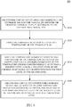
- Fig. 8 is a flowchart illustrating an electric vehicle charging method 800 according to some embodiments of the present disclosure.
- an electric vehicle charging method 800 is discussed in relation to the embodiments shown in figures 1-7 , but is not limited thereto. It will be apparent to those skilled in the art that various modifications and variations can be made without departing from the scope or spirit of the disclosure.
- the electric vehicle charging method 800 includes steps S810, S820, S830, and S840.
- step S810 the control circuit 122 controls the charge gun 140 to charge the electric vehicle 200 through the charging terminal P1-P3, PN according to the control pilot signal Vcp1.
- step S820 the temperature sensor ST1 is used to detect temperature of the charge gun 140.
- step S830 when the temperature sensor ST1 detects that the temperature of the charge gun 140 exceeds the safety limit value, a resistance of the temperature sensor is changed correspondingly, such that a positive level and/or a negative level of the control pilot signal Vcp1 is switched from the first level to the second level.
- the temperature sensor ST1 includes a temperature switch, and the temperature switch is turned off when the temperature of the charge gun 140 is lower than the safety limit value, and the temperature switch is turned on when the temperature of the charge gun 140 exceeds the safety limit value.
- step S840 the control circuit 122 controls the charging device 100a to activate an over temperature protection according to the control pilot signal Vcp1 when the positive level or the negative level of the control pilot signal Vcp1 is at the second level.
- the control circuit 122 controls the charge gun 140 of the charging device 100a to stop charging the electric vehicle 200.
- the control circuit 122 may also control the charging device 100a to lower the output to the electric vehicle 200, or to output a warning signal, but the present disclosure is not limited thereto.
- One skilled in the art may perform various over temperature protections by properly arranging the control circuit 122, in order to prevent the burnout of the elements and circuits in the system under high temperature and ensure the safety of the users.
- the over temperature detecting circuit arranged in the charge gun is used to control the voltage level of the control pilot signal. Therefore, the control circuit in the control module may determine whether the temperature of the charge gun exceeds the safety limit value by detecting the control pilot signal, and perform corresponding protection accordingly.
- the elements in the above embodiments may be implemented by various digital or analog circuits, and may also be implemented by different integrated circuit chips. Each element may also be integrated in a single digital control chip. Each control circuit may also be realized by various processors or other integrated circuit chips.
- the above list is merely exemplary and is not meant to be limitations of the present disclosure.
Landscapes
- Engineering & Computer Science (AREA)
- Power Engineering (AREA)
- Transportation (AREA)
- Mechanical Engineering (AREA)
- Life Sciences & Earth Sciences (AREA)
- Sustainable Development (AREA)
- Sustainable Energy (AREA)
- Charge And Discharge Circuits For Batteries Or The Like (AREA)
- Electric Propulsion And Braking For Vehicles (AREA)
Applications Claiming Priority (1)
| Application Number | Priority Date | Filing Date | Title |
|---|---|---|---|
| TW105115259A TWI595722B (zh) | 2016-05-18 | 2016-05-18 | 充電槍與電動車充電設備 |
Publications (3)
| Publication Number | Publication Date |
|---|---|
| EP3246196A1 true EP3246196A1 (de) | 2017-11-22 |
| EP3246196B1 EP3246196B1 (de) | 2025-01-15 |
| EP3246196C0 EP3246196C0 (de) | 2025-01-15 |
Family
ID=57389304
Family Applications (1)
| Application Number | Title | Priority Date | Filing Date |
|---|---|---|---|
| EP16199971.9A Active EP3246196B1 (de) | 2016-05-18 | 2016-11-22 | Ladepistole und ladeverfahren für elektrisches fahrzeug |
Country Status (3)
| Country | Link |
|---|---|
| US (1) | US10227014B2 (de) |
| EP (1) | EP3246196B1 (de) |
| TW (1) | TWI595722B (de) |
Cited By (3)
| Publication number | Priority date | Publication date | Assignee | Title |
|---|---|---|---|---|
| CN109050329A (zh) * | 2018-09-14 | 2018-12-21 | 北京新能源汽车股份有限公司 | 直流充电控制导引电路、适配接口电路及充电控制方法 |
| WO2020178797A1 (en) * | 2019-03-07 | 2020-09-10 | Te Connectivity Corporation | Isolated temperature sensing for electrical terminals |
| CN117162849A (zh) * | 2023-10-31 | 2023-12-05 | 万帮数字能源股份有限公司 | 多枪同充充电系统及其通信系统、充电桩 |
Families Citing this family (30)
| Publication number | Priority date | Publication date | Assignee | Title |
|---|---|---|---|---|
| KR101587357B1 (ko) * | 2014-09-01 | 2016-01-20 | 엘에스산전 주식회사 | 차량 충전 장치 및 충전 방법 |
| US10661673B2 (en) | 2016-12-20 | 2020-05-26 | Eaton Intelligent Power Limited | Pilot signal detection and indication unit and electric vehicle charging system including the same |
| CN207265713U (zh) * | 2017-07-28 | 2018-04-20 | 特斯拉公司 | 具有热保护的充电系统 |
| CN110014983B (zh) * | 2017-11-26 | 2021-05-14 | 台达电子工业股份有限公司 | 车载充电装置及其操作方法 |
| US11318844B2 (en) | 2017-11-26 | 2022-05-03 | Delta Electronics, Inc. | On-board charging device and operating method thereof |
| CN109130909B (zh) * | 2018-07-27 | 2023-11-10 | 广州万城万充新能源科技有限公司 | 一种电动汽车传导充电的智能连接装置 |
| JP2021180532A (ja) * | 2018-08-09 | 2021-11-18 | 株式会社豊田自動織機 | 充電装置 |
| US11186191B2 (en) * | 2018-12-07 | 2021-11-30 | Delta Electronics, Inc. | Charging device for electric vehicle |
| TWI754843B (zh) * | 2018-12-07 | 2022-02-11 | 台達電子工業股份有限公司 | 電動車之充電設備 |
| KR101996603B1 (ko) * | 2018-12-19 | 2019-07-04 | 중앙제어 주식회사 | 전기차 충전 시 전기차 충전기의 온도를 센싱하는 장치 |
| CN110001429B (zh) * | 2019-04-22 | 2020-11-13 | 乐清泰起知识产权服务有限公司 | 一种新能源电动车用充电枪 |
| DE102019212431B3 (de) * | 2019-08-20 | 2020-11-19 | Volkswagen Aktiengesellschaft | Ladedose eines Elektro- oder Hybridfahrzeuges |
| US11241973B2 (en) * | 2020-02-17 | 2022-02-08 | Ford Global Technologies, Llc | Pilot control circuit for charging a vehicle with a charging station |
| DE102020121544A1 (de) * | 2020-08-17 | 2022-02-17 | Bayerische Motoren Werke Aktiengesellschaft | Steckverbindungselement, sowie eine Vorrichtung zur Überwachung eines Steckverbindungselements |
| CN111953055B (zh) * | 2020-09-14 | 2025-05-13 | 广汽丰田汽车有限公司 | 充电保护电路、方法及装置 |
| CN112744101B (zh) * | 2020-12-25 | 2023-02-17 | 中国第一汽车股份有限公司 | 充放电控制系统、方法及交通工具 |
| CN115556613B (zh) * | 2021-07-02 | 2025-12-12 | 比亚迪股份有限公司 | 车辆、控制导引电路和充电控制方法 |
| KR102395910B1 (ko) * | 2021-07-06 | 2022-05-10 | 주식회사 이엘일렉트릭 | 전기차량용 충전건 장치 |
| CN117940306A (zh) * | 2021-09-24 | 2024-04-26 | 华为技术有限公司 | 挂枪状态的检测方法及装置 |
| CN113809715B (zh) * | 2021-09-25 | 2023-12-08 | 浙江巨磁智能技术有限公司 | 一种用于ic-cpd的高集成度多功能保护方法 |
| US11780607B2 (en) * | 2021-10-31 | 2023-10-10 | Beta Air, Llc | Connector with ambience monitoring capability and methods of use for charging an electric aircraft |
| US12344117B2 (en) * | 2021-10-31 | 2025-07-01 | Beta Air Llc | Systems and methods for a charging port of an electric vehicle |
| US11437763B1 (en) * | 2021-10-31 | 2022-09-06 | Beta Air, Llc | Systems and methods for an electric aircraft charging connector |
| CN114383748A (zh) * | 2022-01-21 | 2022-04-22 | 菲尼克斯(南京)新能源汽车技术有限公司 | 充电枪温度监测系统和方法 |
| TWI849402B (zh) * | 2022-04-08 | 2024-07-21 | 飛宏科技股份有限公司 | 直流充電樁中控制導引點異常的偵測電路 |
| CN116788069A (zh) * | 2023-06-12 | 2023-09-22 | 安百拓贸易有限公司 | 电动工程车辆及其充电导引方法 |
| CN116819217B (zh) * | 2023-08-08 | 2024-05-03 | 康思立达(上海)汽车科技有限公司 | 一种新能源汽车充电枪检修试验台 |
| CN117207793B (zh) * | 2023-08-29 | 2026-01-30 | 惠州亿纬锂能股份有限公司 | 充电系统及充电确认方法 |
| TWI892466B (zh) * | 2024-02-07 | 2025-08-01 | 昊德創新股份有限公司 | 電動載具充電系統 |
| CN119239378B (zh) * | 2024-12-09 | 2025-04-18 | 上海壹徕科技股份有限公司 | 基于充电枪发热的电流控制方法及控制装置 |
Citations (5)
| Publication number | Priority date | Publication date | Assignee | Title |
|---|---|---|---|---|
| WO2012129104A1 (en) * | 2011-03-18 | 2012-09-27 | Aerovironment, Inc. | Electric vehicle supply equipment with temperature-controlled current |
| FR2973962A1 (fr) * | 2011-04-06 | 2012-10-12 | Peugeot Citroen Automobiles Sa | Systeme de charge d'un vehicule electrique ou hybride |
| US20140266040A1 (en) * | 2013-03-14 | 2014-09-18 | Tyco Electronics Corporation | Electric vehicle supply equipment having increased communication capabilities |
| FR3011688A1 (fr) * | 2013-10-08 | 2015-04-10 | Renault Sa | Prise electrique securisee en temperature |
| MX2015014994A (es) * | 2014-11-18 | 2016-05-17 | Schneider Electric Usa Inc | Mango de equipo de alimentacion de vehiculos electricos (evse) con apagado termico automatico por coeficiente de temperatura negativo a tierra. |
Family Cites Families (13)
| Publication number | Priority date | Publication date | Assignee | Title |
|---|---|---|---|---|
| JP4727636B2 (ja) * | 2007-09-13 | 2011-07-20 | トヨタ自動車株式会社 | 車両の充電制御装置および車両 |
| JP4375472B2 (ja) * | 2007-10-23 | 2009-12-02 | トヨタ自動車株式会社 | 車両の充電制御装置 |
| US20090167537A1 (en) | 2007-12-28 | 2009-07-02 | Feliss Norbert A | Minimizing electrical outlet safety failures due to over temperature condition |
| WO2012099978A2 (en) | 2011-01-19 | 2012-07-26 | Aerovironment, Inc. | Electric vehicle docking connector with embedded evse controller |
| US8729856B2 (en) * | 2011-02-23 | 2014-05-20 | Lear Corporation | Thermal wall plug sensing and control |
| US20130134933A1 (en) * | 2011-11-29 | 2013-05-30 | Delphi Technologies, Inc. | Power safety system and method having a plurality of thermally-triggered electrical breaking arrangements |
| WO2013097824A1 (zh) * | 2011-12-31 | 2013-07-04 | 深圳市比亚迪汽车研发有限公司 | 电动汽车及用于电动汽车的动力系统和电机控制器 |
| KR20140003082A (ko) | 2012-06-29 | 2014-01-09 | 엘에스산전 주식회사 | 전기 자동차용 충전기 |
| CN104249630B (zh) * | 2013-06-28 | 2017-08-04 | 比亚迪股份有限公司 | 电动汽车及电动汽车向外供电的系统 |
| CN104249629B (zh) * | 2013-06-28 | 2016-09-07 | 比亚迪股份有限公司 | 电动汽车、电动汽车的动力系统和动力电池的充电方法 |
| US9804034B2 (en) * | 2014-11-14 | 2017-10-31 | Schneider Electric USA, Inc. | EVSE with cordset handle temperature measurement |
| US9573478B2 (en) * | 2014-11-14 | 2017-02-21 | Schneider Electric USA, Inc. | EVSE doubler add-on unit |
| CN204497757U (zh) | 2014-12-04 | 2015-07-22 | 普天新能源(深圳)有限公司 | 充电电路及充电系统 |
-
2016
- 2016-05-18 TW TW105115259A patent/TWI595722B/zh active
- 2016-10-28 US US15/336,804 patent/US10227014B2/en active Active
- 2016-11-22 EP EP16199971.9A patent/EP3246196B1/de active Active
Patent Citations (6)
| Publication number | Priority date | Publication date | Assignee | Title |
|---|---|---|---|---|
| WO2012129104A1 (en) * | 2011-03-18 | 2012-09-27 | Aerovironment, Inc. | Electric vehicle supply equipment with temperature-controlled current |
| FR2973962A1 (fr) * | 2011-04-06 | 2012-10-12 | Peugeot Citroen Automobiles Sa | Systeme de charge d'un vehicule electrique ou hybride |
| US20140266040A1 (en) * | 2013-03-14 | 2014-09-18 | Tyco Electronics Corporation | Electric vehicle supply equipment having increased communication capabilities |
| FR3011688A1 (fr) * | 2013-10-08 | 2015-04-10 | Renault Sa | Prise electrique securisee en temperature |
| MX2015014994A (es) * | 2014-11-18 | 2016-05-17 | Schneider Electric Usa Inc | Mango de equipo de alimentacion de vehiculos electricos (evse) con apagado termico automatico por coeficiente de temperatura negativo a tierra. |
| EP3025902A1 (de) * | 2014-11-18 | 2016-06-01 | Schneider Electric USA, Inc. | Evse-griff mit automatischer thermischer abschaltung durch anschliessen des ntc an die masse |
Cited By (6)
| Publication number | Priority date | Publication date | Assignee | Title |
|---|---|---|---|---|
| CN109050329A (zh) * | 2018-09-14 | 2018-12-21 | 北京新能源汽车股份有限公司 | 直流充电控制导引电路、适配接口电路及充电控制方法 |
| WO2020178797A1 (en) * | 2019-03-07 | 2020-09-10 | Te Connectivity Corporation | Isolated temperature sensing for electrical terminals |
| US11714008B2 (en) | 2019-03-07 | 2023-08-01 | Te Connectivity Solutions Gmbh | Isolated temperature sensing for hems contacts |
| US12066336B2 (en) | 2019-03-07 | 2024-08-20 | Te Connectivity Solutions Gmbh | Isolated temperature sensing for hems contacts |
| CN117162849A (zh) * | 2023-10-31 | 2023-12-05 | 万帮数字能源股份有限公司 | 多枪同充充电系统及其通信系统、充电桩 |
| CN117162849B (zh) * | 2023-10-31 | 2024-03-22 | 万帮数字能源股份有限公司 | 多枪同充充电系统及其通信系统、充电桩 |
Also Published As
| Publication number | Publication date |
|---|---|
| EP3246196B1 (de) | 2025-01-15 |
| US20170334301A1 (en) | 2017-11-23 |
| TW201742344A (zh) | 2017-12-01 |
| US10227014B2 (en) | 2019-03-12 |
| TWI595722B (zh) | 2017-08-11 |
| EP3246196C0 (de) | 2025-01-15 |
Similar Documents
| Publication | Publication Date | Title |
|---|---|---|
| US10227014B2 (en) | Charge gun, electric vehicle supply equipment, and electric vehicle charging method thereof | |
| US11186191B2 (en) | Charging device for electric vehicle | |
| CN107404132B (zh) | 充电枪与电动车充电设备 | |
| US10044180B2 (en) | Electronic circuit breaker for an electrical load in an on-board electrical system of a motor vehicle | |
| JP6641862B2 (ja) | 電流制限回路、直流電力供給コネクタ及び直流電源装置 | |
| WO2016147179A1 (en) | Automatic, highly reliable, fully redundant electronic circuit breaker that includes means for preventing short-circuit overcurrent | |
| US20160241027A1 (en) | Mobile power packs, power control methods and electrical connection devices | |
| US11329474B2 (en) | Switching controller with adaptive overheating protection | |
| US20200395780A1 (en) | Charge control apparatus, energy storage apparatus, and charging method | |
| KR20170099672A (ko) | 배터리 보호 회로 | |
| EP3933421A1 (de) | Detektionsschaltung und detektionsverfahren für eine elektrische steuerungsvorrichtung und elektrofahrzeug | |
| US20150137754A1 (en) | Charging system, vehicle comprising the same and method for controlling charging vehicle with the same | |
| US9321360B2 (en) | Electronic control unit | |
| WO2018116741A1 (ja) | 電源システム | |
| JP2018054390A (ja) | 電圧検出装置 | |
| US9148008B2 (en) | Over current protection apparatus | |
| JP2006340450A (ja) | 電池保護回路 | |
| KR20160114797A (ko) | 전자 스위칭 장치 | |
| EP4005053B1 (de) | Stromversorgungssystem mit schutz gegen stromschwankungen | |
| CN109922563B (zh) | 一种应急灯装置和应急灯控制集成电路 | |
| US20060232901A1 (en) | Arrangement for protecting an electrical device | |
| US8553377B2 (en) | Electronic control device | |
| CN212435348U (zh) | 车载ecu输出电源的过流保护电路 | |
| WO2012020571A1 (en) | Electronic circuit | |
| US20030011248A1 (en) | Error recognition device for a multi-voltage vehicle electrical system |
Legal Events
| Date | Code | Title | Description |
|---|---|---|---|
| PUAI | Public reference made under article 153(3) epc to a published international application that has entered the european phase |
Free format text: ORIGINAL CODE: 0009012 |
|
| STAA | Information on the status of an ep patent application or granted ep patent |
Free format text: STATUS: THE APPLICATION HAS BEEN PUBLISHED |
|
| AK | Designated contracting states |
Kind code of ref document: A1 Designated state(s): AL AT BE BG CH CY CZ DE DK EE ES FI FR GB GR HR HU IE IS IT LI LT LU LV MC MK MT NL NO PL PT RO RS SE SI SK SM TR |
|
| AX | Request for extension of the european patent |
Extension state: BA ME |
|
| STAA | Information on the status of an ep patent application or granted ep patent |
Free format text: STATUS: REQUEST FOR EXAMINATION WAS MADE |
|
| 17P | Request for examination filed |
Effective date: 20180522 |
|
| RBV | Designated contracting states (corrected) |
Designated state(s): AL AT BE BG CH CY CZ DE DK EE ES FI FR GB GR HR HU IE IS IT LI LT LU LV MC MK MT NL NO PL PT RO RS SE SI SK SM TR |
|
| STAA | Information on the status of an ep patent application or granted ep patent |
Free format text: STATUS: EXAMINATION IS IN PROGRESS |
|
| 17Q | First examination report despatched |
Effective date: 20201009 |
|
| REG | Reference to a national code |
Ref country code: DE Free format text: PREVIOUS MAIN CLASS: B60L0011180000 Ref country code: DE Ref legal event code: R079 Ref document number: 602016090935 Country of ref document: DE Free format text: PREVIOUS MAIN CLASS: B60L0011180000 Ipc: B60L0053180000 |
|
| RIC1 | Information provided on ipc code assigned before grant |
Ipc: B60L 53/18 20190101AFI20230530BHEP |
|
| GRAP | Despatch of communication of intention to grant a patent |
Free format text: ORIGINAL CODE: EPIDOSNIGR1 |
|
| STAA | Information on the status of an ep patent application or granted ep patent |
Free format text: STATUS: GRANT OF PATENT IS INTENDED |
|
| INTG | Intention to grant announced |
Effective date: 20240805 |
|
| GRAS | Grant fee paid |
Free format text: ORIGINAL CODE: EPIDOSNIGR3 |
|
| GRAA | (expected) grant |
Free format text: ORIGINAL CODE: 0009210 |
|
| STAA | Information on the status of an ep patent application or granted ep patent |
Free format text: STATUS: THE PATENT HAS BEEN GRANTED |
|
| AK | Designated contracting states |
Kind code of ref document: B1 Designated state(s): AL AT BE BG CH CY CZ DE DK EE ES FI FR GB GR HR HU IE IS IT LI LT LU LV MC MK MT NL NO PL PT RO RS SE SI SK SM TR |
|
| REG | Reference to a national code |
Ref country code: CH Ref legal event code: EP Ref country code: GB Ref legal event code: FG4D |
|
| REG | Reference to a national code |
Ref country code: DE Ref legal event code: R096 Ref document number: 602016090935 Country of ref document: DE |
|
| REG | Reference to a national code |
Ref country code: IE Ref legal event code: FG4D |
|
| U01 | Request for unitary effect filed |
Effective date: 20250214 |
|
| U07 | Unitary effect registered |
Designated state(s): AT BE BG DE DK EE FI FR IT LT LU LV MT NL PT RO SE SI Effective date: 20250220 |
|
| PG25 | Lapsed in a contracting state [announced via postgrant information from national office to epo] |
Ref country code: RS Free format text: LAPSE BECAUSE OF FAILURE TO SUBMIT A TRANSLATION OF THE DESCRIPTION OR TO PAY THE FEE WITHIN THE PRESCRIBED TIME-LIMIT Effective date: 20250415 |
|
| PG25 | Lapsed in a contracting state [announced via postgrant information from national office to epo] |
Ref country code: PL Free format text: LAPSE BECAUSE OF FAILURE TO SUBMIT A TRANSLATION OF THE DESCRIPTION OR TO PAY THE FEE WITHIN THE PRESCRIBED TIME-LIMIT Effective date: 20250115 |
|
| PG25 | Lapsed in a contracting state [announced via postgrant information from national office to epo] |
Ref country code: ES Free format text: LAPSE BECAUSE OF FAILURE TO SUBMIT A TRANSLATION OF THE DESCRIPTION OR TO PAY THE FEE WITHIN THE PRESCRIBED TIME-LIMIT Effective date: 20250115 |
|
| PG25 | Lapsed in a contracting state [announced via postgrant information from national office to epo] |
Ref country code: IS Free format text: LAPSE BECAUSE OF FAILURE TO SUBMIT A TRANSLATION OF THE DESCRIPTION OR TO PAY THE FEE WITHIN THE PRESCRIBED TIME-LIMIT Effective date: 20250515 Ref country code: NO Free format text: LAPSE BECAUSE OF FAILURE TO SUBMIT A TRANSLATION OF THE DESCRIPTION OR TO PAY THE FEE WITHIN THE PRESCRIBED TIME-LIMIT Effective date: 20250415 |
|
| PG25 | Lapsed in a contracting state [announced via postgrant information from national office to epo] |
Ref country code: HR Free format text: LAPSE BECAUSE OF FAILURE TO SUBMIT A TRANSLATION OF THE DESCRIPTION OR TO PAY THE FEE WITHIN THE PRESCRIBED TIME-LIMIT Effective date: 20250115 |
|
| PG25 | Lapsed in a contracting state [announced via postgrant information from national office to epo] |
Ref country code: GR Free format text: LAPSE BECAUSE OF FAILURE TO SUBMIT A TRANSLATION OF THE DESCRIPTION OR TO PAY THE FEE WITHIN THE PRESCRIBED TIME-LIMIT Effective date: 20250416 |
|
| PG25 | Lapsed in a contracting state [announced via postgrant information from national office to epo] |
Ref country code: SM Free format text: LAPSE BECAUSE OF FAILURE TO SUBMIT A TRANSLATION OF THE DESCRIPTION OR TO PAY THE FEE WITHIN THE PRESCRIBED TIME-LIMIT Effective date: 20250115 |
|
| PG25 | Lapsed in a contracting state [announced via postgrant information from national office to epo] |
Ref country code: CZ Free format text: LAPSE BECAUSE OF FAILURE TO SUBMIT A TRANSLATION OF THE DESCRIPTION OR TO PAY THE FEE WITHIN THE PRESCRIBED TIME-LIMIT Effective date: 20250115 |
|
| PG25 | Lapsed in a contracting state [announced via postgrant information from national office to epo] |
Ref country code: SK Free format text: LAPSE BECAUSE OF FAILURE TO SUBMIT A TRANSLATION OF THE DESCRIPTION OR TO PAY THE FEE WITHIN THE PRESCRIBED TIME-LIMIT Effective date: 20250115 |
|
| U20 | Renewal fee for the european patent with unitary effect paid |
Year of fee payment: 10 Effective date: 20251008 |
|
| PLBE | No opposition filed within time limit |
Free format text: ORIGINAL CODE: 0009261 |
|
| STAA | Information on the status of an ep patent application or granted ep patent |
Free format text: STATUS: NO OPPOSITION FILED WITHIN TIME LIMIT |
|
| 26N | No opposition filed |
Effective date: 20251016 |
|
| PGFP | Annual fee paid to national office [announced via postgrant information from national office to epo] |
Ref country code: GB Payment date: 20251001 Year of fee payment: 10 |