EP3246199A1 - Accoudoir - Google Patents
Accoudoir Download PDFInfo
- Publication number
- EP3246199A1 EP3246199A1 EP17000695.1A EP17000695A EP3246199A1 EP 3246199 A1 EP3246199 A1 EP 3246199A1 EP 17000695 A EP17000695 A EP 17000695A EP 3246199 A1 EP3246199 A1 EP 3246199A1
- Authority
- EP
- European Patent Office
- Prior art keywords
- support arm
- spring
- end position
- armrest
- locking means
- Prior art date
- Legal status (The legal status is an assumption and is not a legal conclusion. Google has not performed a legal analysis and makes no representation as to the accuracy of the status listed.)
- Granted
Links
Images



Classifications
-
- B—PERFORMING OPERATIONS; TRANSPORTING
- B60—VEHICLES IN GENERAL
- B60N—SEATS SPECIALLY ADAPTED FOR VEHICLES; VEHICLE PASSENGER ACCOMMODATION NOT OTHERWISE PROVIDED FOR
- B60N3/00—Arrangements or adaptations of other passenger fittings, not otherwise provided for
-
- B—PERFORMING OPERATIONS; TRANSPORTING
- B60—VEHICLES IN GENERAL
- B60N—SEATS SPECIALLY ADAPTED FOR VEHICLES; VEHICLE PASSENGER ACCOMMODATION NOT OTHERWISE PROVIDED FOR
- B60N2/00—Seats specially adapted for vehicles; Arrangement or mounting of seats in vehicles
- B60N2/75—Arm-rests
- B60N2/79—Adaptations for additional use of the arm-rests
- B60N2/793—Adaptations for additional use of the arm-rests for use as storage compartments
-
- B—PERFORMING OPERATIONS; TRANSPORTING
- B60—VEHICLES IN GENERAL
- B60N—SEATS SPECIALLY ADAPTED FOR VEHICLES; VEHICLE PASSENGER ACCOMMODATION NOT OTHERWISE PROVIDED FOR
- B60N2/00—Seats specially adapted for vehicles; Arrangement or mounting of seats in vehicles
- B60N2/75—Arm-rests
- B60N2/753—Arm-rests movable to an inoperative position
-
- B—PERFORMING OPERATIONS; TRANSPORTING
- B60—VEHICLES IN GENERAL
- B60N—SEATS SPECIALLY ADAPTED FOR VEHICLES; VEHICLE PASSENGER ACCOMMODATION NOT OTHERWISE PROVIDED FOR
- B60N2/00—Seats specially adapted for vehicles; Arrangement or mounting of seats in vehicles
- B60N2/75—Arm-rests
- B60N2/763—Arm-rests adjustable
- B60N2/767—Angle adjustment
-
- B—PERFORMING OPERATIONS; TRANSPORTING
- B60—VEHICLES IN GENERAL
- B60R—VEHICLES, VEHICLE FITTINGS, OR VEHICLE PARTS, NOT OTHERWISE PROVIDED FOR
- B60R7/00—Stowing or holding appliances inside vehicle primarily intended for personal property smaller than suit-cases, e.g. travelling articles, or maps
- B60R7/04—Stowing or holding appliances inside vehicle primarily intended for personal property smaller than suit-cases, e.g. travelling articles, or maps in driver or passenger space, e.g. using racks
-
- G—PHYSICS
- G05—CONTROLLING; REGULATING
- G05G—CONTROL DEVICES OR SYSTEMS INSOFAR AS CHARACTERISED BY MECHANICAL FEATURES ONLY
- G05G1/00—Controlling members, e.g. knobs or handles; Assemblies or arrangements thereof; Indicating position of controlling members
- G05G1/58—Rests or guides for relevant parts of the operator's body
- G05G1/62—Arm rests
-
- B—PERFORMING OPERATIONS; TRANSPORTING
- B60—VEHICLES IN GENERAL
- B60N—SEATS SPECIALLY ADAPTED FOR VEHICLES; VEHICLE PASSENGER ACCOMMODATION NOT OTHERWISE PROVIDED FOR
- B60N2/00—Seats specially adapted for vehicles; Arrangement or mounting of seats in vehicles
- B60N2/75—Arm-rests
Definitions
- the invention relates to an armrest for a seat, in particular a vehicle seat.
- the armrest may e.g. Be part of a console of a vehicle.
- the armrest comprises a base part, e.g. may be formed of parts of the seat or of a fixed structure, in particular a vehicle structure.
- a support arm is mounted on the base and movable between a first end position and a second end position. The support arm can be locked in at least one position. The support arm can then not move out of this end position unintentionally.
- the armrest includes a base and a support arm pivotally mounted to the base between a first end position and a second end position.
- a spring loads the support arm in the direction of an end position.
- the support arm can be locked relative to the base in at least one position by means of a locking device.
- the locking device comprises the first arm associated with the first locking means, which cooperate with second locking means, which are associated with the base part.
- the spring is associated with the first or the second locking means. These may be formed, for example, by a specific shape of the spring.
- the locking takes place, for example, in the upper end position of the support arm. As the upper end position we refer to the position of the support arm, in which the support arm is arranged approximately vertically.
- the spring is e.g. formed in one piece.
- the spring may e.g. be formed as a leaf spring.
- the spring is a leg spring having a first and a second spring leg.
- This has the advantage that the thighs e.g. different functions, such as support function, attachment function or locking function, can come.
- At least one of the spring legs is e.g. freely movable. Due to the restoring force of the spring, the spring leg moves back to its original position after its deformation.
- the spring includes a mounting portion that cooperates with retaining means of the support arm or the base.
- the attachment area is e.g. attached to the support arm or to the base and arranged immovably thereto.
- the attachment portion cooperates with the retaining means to secure the spring to the support arm or to the base.
- At least one of the spring legs is movable relative to the mounting area.
- the spring legs form e.g. Angled portions of the attachment area that are pivotable relative to the attachment area.
- a support region of the spring loads the support arm at least in a pivoting region of the support arm in the direction of an end position. That is, the support region may load the support arm over the entire pivoting range in the direction of the end position or only in a partial region of the pivoting angle. This subarea may be, for example, between 15 ° and 50 °, in particular about 25 °.
- the spring is tensioned, for example during the movement of the support arm in the lower end position and has in the lower end position to the maximum voltage. In the movement of the support arm in the direction of the upper end position, the spring relaxes. In the event that the spring loads the support arm into the upper end position only in a partial region of the pivoting region, for example, the support region can only be in contact with the base part or with the support arm in this partial region.
- the locking means are associated with the first spring leg.
- the locking means are e.g. designed so that they require a small amount of travel to be adjusted from the locking position to the release position.
- the support area is e.g. assigned to the second spring leg. This can e.g. be designed so that it can cover a relatively large travel. The spring can then load the support arm over a large pivoting angle into the upper end position.
- the first locking means are e.g. positively engageable with the second locking means into engagement.
- the spring is attached to the support arm or to the base.
- the cooperating form-fitting means can be designed such that when a certain operating force is exceeded on the support arm, the form-fit is automatically released. In other words, as long as the actuating force is fallen below the support arm, the positive engagement remains and the support arm is locked in position.
- the first locking means include, for example, a locking shoulder and the second locking means comprise a bearing surface to prevent movement of the support arm. By a slight movement of the first locking means, the locking shoulder and the contact surface can be disengaged. In this way, the positive connection can be solved.
- the armrest comprises e.g. a locking device by means of which the support arm can be locked in an end position. If e.g. the spring is maximally tensioned in the lower end position, the spring loads the support arm in the direction of the upper end position as soon as the locking device has been moved from the locked position to the unlocked position.
- An armrest as a whole is designated by the reference numeral 10 in the figures.
- Like reference numerals in the various figures indicate corresponding parts, even if small letters are readjusted or omitted.
- the armrest 10 is part of a center console 11 in the present embodiment, but it could also be assigned as a separate armrest to a vehicle seat according to an alternative embodiment.
- the armrest 10 comprises an armrest 12, which is held pivotably about a pivot axis a on a base part 13.
- the armrest 12 has a support arm 14 and a pad 15.
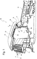
- Fig. 1 the armrest 12 is arranged in a lower end position, which is also referred to as the 0 ° position.
- a support surface 16 is arranged substantially horizontally or with respect to a horizontal only slightly inclined.
- the armrest 12 can be pivoted in the direction u1 in an upper end position, which in Fig. 3 is shown.
- the armrest 12 is pivoted in relation to the lower end position about 90 ° in the direction u1.
- the armrest 10 comprises a locking device 17, with which the support arm 14 in the lower end position is releasably lockable. In a locking position of the locking device 17, the support arm 14 is locked in the lower end position. By means of a button 18 of an actuating device, the locking device 17 can be adjusted to a release position. In the release position, the support arm 14 is no longer locked, so that the armrest 12 can be pivoted from the lower end position in the direction u1.
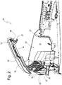
- the armrest 12 is loaded in such a way by a spring 19 in the direction u1, that they after the adjustment of the locking device 17 in the release position of the spring 19 in an intermediate position according to Fig. 2 is moved, in which it is pivoted about 25 ° in the direction u1 with respect to the lower end position.
- the armrest 12 is thus in the intermediate position between the lower end position and the upper end position. If the armrest 12 is to be moved from the intermediate position to the upper end position, the user must manually pivot the armrest 12 in the direction u1 until the upper end position is reached. In the upper end position, the armrest 12 is arranged for example approximately vertically.
- the armrest is automatically locked in the upper end position.
- a force F acts in the direction u2 on the armrest 12, which is so great that the maximum holding force of the locking device 20 is overcome, the armrest 12 moves in the direction u2. In the lower end position, the armrest 12 is automatically locked by the locking device 17.
- the locking device 17 comprises a first locking means 21 held on the support arm 14 and a second locking means 22 held on the base part 13. In the latching position, the locking means 21 and 22 are prevented from moving the armrest 12, and in the release position the locking means 21 and 22 are disengaged.
- the locking means 21 is movable so that it is adjustable by means of the key 18 between the locking position and the release position.
- the locking means 21 is loaded by a restoring force in the locking position.
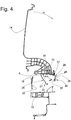
- the armrest 10 comprises the spring 19 (see FIGS Fig. 4 and 5 ), which in the present embodiment of a one-piece leaf spring is formed.
- the spring 19 comprises a fastening region 23 with a projection 35 as well as a free spring leg 25 which forms a support region and a free spring leg 26 which forms a locking region.
- the support arm 14 is shown without the pad 15 in the upper end position.
- the support arm 14 includes attachment means 27 with which the attachment portion 23 of the spring 19 is fixed to the support arm 14.
- the projection 35 cooperates with the base 13 to prevent displacement of the mounting portion 23 parallel to its longitudinal axis.
- the fastening means 27 are aligned such that the fastening region 23 extends approximately radially to the pivot axis a.
- the spring leg 26, however, runs approximately tangentially to the pivot axis a. While the attachment portion 23 is substantially immovable relative to the base, the spring legs 25 and 26 are freely movable and can be elastically deformed against their return force.
- the spring leg 26 comprises a projection 24 which forms a holding surface 36 which is in the upper end position with a counter surface 28 of the base 13 in engagement such that a movement of the support arm 14 is prevented from the upper end position in the direction u2, as long as the actuating force maximum holding force does not exceed.
- the maximum holding force is, for example, such that inertial forces acting on the armrest 12 in normal driving situations do not come from the locking device 20 Move locking position that the vehicle occupant but can move the support arm 14 without excessive force from the upper end position in the direction u2.
- Fig. 7 the lower end position is shown, in which the spring 19 is maximally tensioned. It can be seen that the spring leg 25 is arranged approximately parallel to the attachment region 23.
- the first locking means 21 and the second locking means 22 are also corresponding Fig. 1 moved in engagement, ie, the locking device 17 is in the locking position.
- the locking means 21 and 22 are not shown in Fig. 8.
- the spring 19 moves the support arm 14 again in the direction u1 in a 25 ° position.
- the spring leg 25 pivots in the direction v2 and relaxes.
- the support arm 14 - as mentioned above - be manually pivoted in the direction u1 in the upper end position.
- the retaining surface 36 of the spring leg 25 engages in engagement the mating surface 28 of the base 13 a.
- access to a storage compartment 34 is possible through an opening 33.
- the storage compartment 34 is in the present embodiment, part of the base 13 and formed integrally therewith.
Landscapes
- Engineering & Computer Science (AREA)
- Mechanical Engineering (AREA)
- Transportation (AREA)
- Aviation & Aerospace Engineering (AREA)
- Physics & Mathematics (AREA)
- General Physics & Mathematics (AREA)
- Automation & Control Theory (AREA)
- Seats For Vehicles (AREA)
- Clamps And Clips (AREA)
Applications Claiming Priority (1)
| Application Number | Priority Date | Filing Date | Title |
|---|---|---|---|
| DE102016006087.5A DE102016006087A1 (de) | 2016-05-20 | 2016-05-20 | Armlehne |
Publications (2)
| Publication Number | Publication Date |
|---|---|
| EP3246199A1 true EP3246199A1 (fr) | 2017-11-22 |
| EP3246199B1 EP3246199B1 (fr) | 2020-06-17 |
Family
ID=58632731
Family Applications (1)
| Application Number | Title | Priority Date | Filing Date |
|---|---|---|---|
| EP17000695.1A Active EP3246199B1 (fr) | 2016-05-20 | 2017-04-24 | Accoudoir |
Country Status (4)
| Country | Link |
|---|---|
| US (1) | US10562424B2 (fr) |
| EP (1) | EP3246199B1 (fr) |
| CN (1) | CN107399255B (fr) |
| DE (1) | DE102016006087A1 (fr) |
Cited By (1)
| Publication number | Priority date | Publication date | Assignee | Title |
|---|---|---|---|---|
| US20170334323A1 (en) * | 2016-05-20 | 2017-11-23 | Grammer Ag | Armrest |
Families Citing this family (5)
| Publication number | Priority date | Publication date | Assignee | Title |
|---|---|---|---|---|
| KR101905486B1 (ko) * | 2016-10-10 | 2018-10-10 | 주식회사 서연이화 | 차량용 콘솔 암레스트의 힌지 유닛 |
| CN206581758U (zh) * | 2017-01-25 | 2017-10-24 | 福特环球技术公司 | 锁定装置和扶手控制台 |
| US11104276B2 (en) * | 2019-11-19 | 2021-08-31 | Ford Global Technologies, Llc | Vehicle console assembly having an integrated mounting structure |
| CN117261717A (zh) | 2022-06-15 | 2023-12-22 | 李尔公司 | 具有内部运动阻尼器的扶手组件 |
| CN117261719A (zh) | 2022-06-15 | 2023-12-22 | 李尔公司 | 具有可调节的安装轴的扶手组件 |
Citations (2)
| Publication number | Priority date | Publication date | Assignee | Title |
|---|---|---|---|---|
| US6033015A (en) * | 1996-07-01 | 2000-03-07 | Lear Corporation | Armrest cover positioning mechanism |
| EP2085267A1 (fr) * | 2008-02-04 | 2009-08-05 | Renault S.A.S. | Bac de rangement pour véhicule |
Family Cites Families (22)
| Publication number | Priority date | Publication date | Assignee | Title |
|---|---|---|---|---|
| US2026016A (en) * | 1934-08-02 | 1935-12-31 | Ternstedt Mfg Co | Combined armrest, inside door handle, and pull-to |
| DE2907463C2 (de) * | 1979-02-26 | 1986-05-15 | Ignaz Vogel GmbH & Co KG, 7500 Karlsruhe | Fahrgastsitz |
| US4790579A (en) * | 1988-03-01 | 1988-12-13 | Siemens Energy & Automation, Inc. | Sliding spring latch |
| US5116099A (en) * | 1991-05-14 | 1992-05-26 | Lear Seating Corporation | Mechanical latch locking a cover of pivoting armrest assembly |
| CN2214337Y (zh) * | 1994-09-23 | 1995-12-06 | 宋宁 | 摩托车或自行车后座扶手 |
| DE4443521C1 (de) * | 1994-12-07 | 1996-01-04 | Daimler Benz Ag | Abdeckbarer Behälter für Fahrzeuge |
| DE10234715B8 (de) * | 2002-07-30 | 2008-04-03 | Röchling Automotive AG & Co. KG | Drehbeweglicher Körper mit Entrastelement |
| JP3926789B2 (ja) * | 2003-12-18 | 2007-06-06 | 本田技研工業株式会社 | リッドロック装置 |
| FR2886898B1 (fr) * | 2005-06-09 | 2007-08-31 | Plasthom S A Sa | Accoudoir multi-positions associe a un bac de rangement, notamment pour vehicule automobile |
| DE102005043593B4 (de) * | 2005-09-12 | 2010-12-02 | Faurecia Innenraum Systeme Gmbh | Staufach für ein Kraftfahrzeug |
| DE102005044436B4 (de) * | 2005-09-16 | 2009-02-12 | Lisa Dräxlmaier GmbH | Mittelkonsole für ein Fahrzeug |
| US7390045B2 (en) * | 2006-06-15 | 2008-06-24 | International Automotive Components Group North America, Inc. | System for attaching an article holding assembly to a mounting member in a vehicle |
| DE102007012326B4 (de) * | 2007-03-14 | 2009-11-26 | Lisa Dräxlmaier GmbH | Armlehne für einen Fahrzeugsitz |
| DE102008018321B4 (de) * | 2008-04-11 | 2022-08-04 | Dr. Ing. H.C. F. Porsche Aktiengesellschaft | Mittelkonsole für ein Kraftfahrzeug |
| DE102008023751A1 (de) * | 2008-05-15 | 2009-11-19 | Grammer Ag | Ausstattungsvorrichtung für einen Fahrzeuginnenraum, insbesondere Armlehne für Fahrzeugsitze |
| DE202009004057U1 (de) * | 2009-03-26 | 2010-08-19 | Peguform Gmbh | Klappfach für ein Kraftfahrzeug |
| US8534761B2 (en) * | 2010-05-10 | 2013-09-17 | Be Aerospace, Inc. | Armrest assembly for aircraft passenger seat |
| US8516668B2 (en) * | 2011-10-24 | 2013-08-27 | Venturesource Solutions, Inc. | Torque assembly and method of manufacture |
| DE102011088375B4 (de) * | 2011-12-13 | 2017-02-23 | Lisa Dräxlmaier GmbH | Herstellung eines gewölbten Kunststoff-Rollos für ein Ablagefach |
| JP5890185B2 (ja) * | 2012-01-23 | 2016-03-22 | 豊田合成株式会社 | 車両用コンソールボックス |
| US9925896B2 (en) * | 2014-09-26 | 2018-03-27 | Faurecia Interieur Industrie | Interior system for a vehicle, namely armrest system for a vehicle |
| DE102016006087A1 (de) * | 2016-05-20 | 2017-11-23 | Grammer Ag | Armlehne |
-
2016
- 2016-05-20 DE DE102016006087.5A patent/DE102016006087A1/de not_active Withdrawn
-
2017
- 2017-04-24 EP EP17000695.1A patent/EP3246199B1/fr active Active
- 2017-05-09 CN CN201710319177.1A patent/CN107399255B/zh active Active
- 2017-05-19 US US15/599,790 patent/US10562424B2/en active Active
Patent Citations (2)
| Publication number | Priority date | Publication date | Assignee | Title |
|---|---|---|---|---|
| US6033015A (en) * | 1996-07-01 | 2000-03-07 | Lear Corporation | Armrest cover positioning mechanism |
| EP2085267A1 (fr) * | 2008-02-04 | 2009-08-05 | Renault S.A.S. | Bac de rangement pour véhicule |
Cited By (2)
| Publication number | Priority date | Publication date | Assignee | Title |
|---|---|---|---|---|
| US20170334323A1 (en) * | 2016-05-20 | 2017-11-23 | Grammer Ag | Armrest |
| US10562424B2 (en) * | 2016-05-20 | 2020-02-18 | Grammer Ag | Armrest |
Also Published As
| Publication number | Publication date |
|---|---|
| US20170334323A1 (en) | 2017-11-23 |
| US10562424B2 (en) | 2020-02-18 |
| CN107399255B (zh) | 2020-05-05 |
| CN107399255A (zh) | 2017-11-28 |
| EP3246199B1 (fr) | 2020-06-17 |
| DE102016006087A1 (de) | 2017-11-23 |
Similar Documents
| Publication | Publication Date | Title |
|---|---|---|
| EP3246199B1 (fr) | Accoudoir | |
| DE2708423C2 (de) | Durch Nachvorneschwenken seiner Rückenlehne in eine Einstiegstellung überführbarer, längsverstellbarer Fahrzeugsitz | |
| EP3188929B1 (fr) | Accoudoir | |
| DE69305009T2 (de) | Vorrichtung zur Blockierung eines Fahrzeugsitzes während eines Aufpralls | |
| DE102014111923B4 (de) | Armlehne mit Crashsicherung | |
| DE2655535B2 (de) | Gelenkbeschlag für Kraftfahrzeugsitze | |
| DE2014007B2 (de) | Befestigung eines sicherheitsgurtes an einem fahrzeugsitz | |
| DE3216015A1 (de) | Verankerung fuer das gurtschloss eines sicherheitsgurtes | |
| DE102008003650B4 (de) | Verriegelungssystem für einen einstellbaren Fahrzeugsitz | |
| DE102004061139B4 (de) | Vorverlagerbarer Kfz-Sitz, insbesondere für 2-türige Fahrzeuge | |
| DE102016011331A1 (de) | Armlehne | |
| DE102016200052B4 (de) | Armauflagenvorrichtung für ein Fahrzeug | |
| DE202007012746U1 (de) | Vorrichtung zur Verankerung eines Auto-Kindersitzes an im Fahrzeug unbeweglich festgelegten Verankerungselementen | |
| DE102008033326B4 (de) | Armauflagevorrichtung für Fahrzeugsitze | |
| DE202015104788U1 (de) | Kindersitzsystem zur Anbringung auf einem Kraftfahrzeugsitz | |
| DE102017102429B4 (de) | Armlehne für ein Kraftfahrzeug | |
| DE19500268C1 (de) | Höhenverstellvorrichtung für einen Sicherheitsgurt | |
| DE19718838B4 (de) | Fahrzeugsitz mit einem Sitzgestell und mit einer im fertiggestellten Zustand an dieses Sitzgestell anmontierbaren Rückenlehne | |
| DE102014001980B3 (de) | Kopfstütze für Fahrzeugsitze | |
| DE102012009578B4 (de) | Armlehne für Fahrzeugsitze | |
| DE102009023712B4 (de) | Armlehne mit Fliehkraftpendel | |
| DE1949085C3 (de) | Fahrzeugsitz, insbesondere Kraftfahrzeugsitz | |
| DE3841811C2 (fr) | ||
| DE102017203428B4 (de) | Entriegelungsvorrichtung, Längseinsteller und Fahrzeugsitz | |
| DE102016204563B4 (de) | Vordereinheit für ein Gleitbrett |
Legal Events
| Date | Code | Title | Description |
|---|---|---|---|
| PUAI | Public reference made under article 153(3) epc to a published international application that has entered the european phase |
Free format text: ORIGINAL CODE: 0009012 |
|
| STAA | Information on the status of an ep patent application or granted ep patent |
Free format text: STATUS: THE APPLICATION HAS BEEN PUBLISHED |
|
| AK | Designated contracting states |
Kind code of ref document: A1 Designated state(s): AL AT BE BG CH CY CZ DE DK EE ES FI FR GB GR HR HU IE IS IT LI LT LU LV MC MK MT NL NO PL PT RO RS SE SI SK SM TR |
|
| AX | Request for extension of the european patent |
Extension state: BA ME |
|
| STAA | Information on the status of an ep patent application or granted ep patent |
Free format text: STATUS: REQUEST FOR EXAMINATION WAS MADE |
|
| 17P | Request for examination filed |
Effective date: 20180302 |
|
| RBV | Designated contracting states (corrected) |
Designated state(s): AL AT BE BG CH CY CZ DE DK EE ES FI FR GB GR HR HU IE IS IT LI LT LU LV MC MK MT NL NO PL PT RO RS SE SI SK SM TR |
|
| REG | Reference to a national code |
Ref country code: DE Ref legal event code: R079 Ref document number: 502017005686 Country of ref document: DE Free format text: PREVIOUS MAIN CLASS: B60N0002460000 Ipc: B60N0002750000 |
|
| RIC1 | Information provided on ipc code assigned before grant |
Ipc: B60N 2/75 20180101AFI20191031BHEP |
|
| GRAP | Despatch of communication of intention to grant a patent |
Free format text: ORIGINAL CODE: EPIDOSNIGR1 |
|
| STAA | Information on the status of an ep patent application or granted ep patent |
Free format text: STATUS: GRANT OF PATENT IS INTENDED |
|
| INTG | Intention to grant announced |
Effective date: 20200115 |
|
| RIN1 | Information on inventor provided before grant (corrected) |
Inventor name: STUIBER, MARTIN Inventor name: KONE, ALY |
|
| GRAS | Grant fee paid |
Free format text: ORIGINAL CODE: EPIDOSNIGR3 |
|
| GRAA | (expected) grant |
Free format text: ORIGINAL CODE: 0009210 |
|
| STAA | Information on the status of an ep patent application or granted ep patent |
Free format text: STATUS: THE PATENT HAS BEEN GRANTED |
|
| AK | Designated contracting states |
Kind code of ref document: B1 Designated state(s): AL AT BE BG CH CY CZ DE DK EE ES FI FR GB GR HR HU IE IS IT LI LT LU LV MC MK MT NL NO PL PT RO RS SE SI SK SM TR |
|
| REG | Reference to a national code |
Ref country code: GB Ref legal event code: FG4D Free format text: NOT ENGLISH |
|
| REG | Reference to a national code |
Ref country code: CH Ref legal event code: EP |
|
| REG | Reference to a national code |
Ref country code: DE Ref legal event code: R096 Ref document number: 502017005686 Country of ref document: DE |
|
| REG | Reference to a national code |
Ref country code: IE Ref legal event code: FG4D Free format text: LANGUAGE OF EP DOCUMENT: GERMAN |
|
| REG | Reference to a national code |
Ref country code: AT Ref legal event code: REF Ref document number: 1280914 Country of ref document: AT Kind code of ref document: T Effective date: 20200715 |
|
| PG25 | Lapsed in a contracting state [announced via postgrant information from national office to epo] |
Ref country code: LT Free format text: LAPSE BECAUSE OF FAILURE TO SUBMIT A TRANSLATION OF THE DESCRIPTION OR TO PAY THE FEE WITHIN THE PRESCRIBED TIME-LIMIT Effective date: 20200617 Ref country code: FI Free format text: LAPSE BECAUSE OF FAILURE TO SUBMIT A TRANSLATION OF THE DESCRIPTION OR TO PAY THE FEE WITHIN THE PRESCRIBED TIME-LIMIT Effective date: 20200617 Ref country code: NO Free format text: LAPSE BECAUSE OF FAILURE TO SUBMIT A TRANSLATION OF THE DESCRIPTION OR TO PAY THE FEE WITHIN THE PRESCRIBED TIME-LIMIT Effective date: 20200917 Ref country code: SE Free format text: LAPSE BECAUSE OF FAILURE TO SUBMIT A TRANSLATION OF THE DESCRIPTION OR TO PAY THE FEE WITHIN THE PRESCRIBED TIME-LIMIT Effective date: 20200617 Ref country code: GR Free format text: LAPSE BECAUSE OF FAILURE TO SUBMIT A TRANSLATION OF THE DESCRIPTION OR TO PAY THE FEE WITHIN THE PRESCRIBED TIME-LIMIT Effective date: 20200918 |
|
| REG | Reference to a national code |
Ref country code: LT Ref legal event code: MG4D |
|
| REG | Reference to a national code |
Ref country code: NL Ref legal event code: MP Effective date: 20200617 |
|
| PG25 | Lapsed in a contracting state [announced via postgrant information from national office to epo] |
Ref country code: BG Free format text: LAPSE BECAUSE OF FAILURE TO SUBMIT A TRANSLATION OF THE DESCRIPTION OR TO PAY THE FEE WITHIN THE PRESCRIBED TIME-LIMIT Effective date: 20200917 Ref country code: LV Free format text: LAPSE BECAUSE OF FAILURE TO SUBMIT A TRANSLATION OF THE DESCRIPTION OR TO PAY THE FEE WITHIN THE PRESCRIBED TIME-LIMIT Effective date: 20200617 Ref country code: RS Free format text: LAPSE BECAUSE OF FAILURE TO SUBMIT A TRANSLATION OF THE DESCRIPTION OR TO PAY THE FEE WITHIN THE PRESCRIBED TIME-LIMIT Effective date: 20200617 Ref country code: HR Free format text: LAPSE BECAUSE OF FAILURE TO SUBMIT A TRANSLATION OF THE DESCRIPTION OR TO PAY THE FEE WITHIN THE PRESCRIBED TIME-LIMIT Effective date: 20200617 |
|
| REG | Reference to a national code |
Ref country code: DE Ref legal event code: R082 Ref document number: 502017005686 Country of ref document: DE Representative=s name: PATENTANWAELTE ROCHE, VON WESTERNHAGEN & EHRES, DE Ref country code: DE Ref legal event code: R081 Ref document number: 502017005686 Country of ref document: DE Owner name: GRAMMER AKTIENGESELLSCHAFT, DE Free format text: FORMER OWNER: GRAMMER AG, 92224 AMBERG, DE |
|
| PG25 | Lapsed in a contracting state [announced via postgrant information from national office to epo] |
Ref country code: AL Free format text: LAPSE BECAUSE OF FAILURE TO SUBMIT A TRANSLATION OF THE DESCRIPTION OR TO PAY THE FEE WITHIN THE PRESCRIBED TIME-LIMIT Effective date: 20200617 Ref country code: NL Free format text: LAPSE BECAUSE OF FAILURE TO SUBMIT A TRANSLATION OF THE DESCRIPTION OR TO PAY THE FEE WITHIN THE PRESCRIBED TIME-LIMIT Effective date: 20200617 |
|
| RAP2 | Party data changed (patent owner data changed or rights of a patent transferred) |
Owner name: GRAMMER AG |
|
| PG25 | Lapsed in a contracting state [announced via postgrant information from national office to epo] |
Ref country code: EE Free format text: LAPSE BECAUSE OF FAILURE TO SUBMIT A TRANSLATION OF THE DESCRIPTION OR TO PAY THE FEE WITHIN THE PRESCRIBED TIME-LIMIT Effective date: 20200617 Ref country code: SM Free format text: LAPSE BECAUSE OF FAILURE TO SUBMIT A TRANSLATION OF THE DESCRIPTION OR TO PAY THE FEE WITHIN THE PRESCRIBED TIME-LIMIT Effective date: 20200617 Ref country code: ES Free format text: LAPSE BECAUSE OF FAILURE TO SUBMIT A TRANSLATION OF THE DESCRIPTION OR TO PAY THE FEE WITHIN THE PRESCRIBED TIME-LIMIT Effective date: 20200617 Ref country code: RO Free format text: LAPSE BECAUSE OF FAILURE TO SUBMIT A TRANSLATION OF THE DESCRIPTION OR TO PAY THE FEE WITHIN THE PRESCRIBED TIME-LIMIT Effective date: 20200617 Ref country code: CZ Free format text: LAPSE BECAUSE OF FAILURE TO SUBMIT A TRANSLATION OF THE DESCRIPTION OR TO PAY THE FEE WITHIN THE PRESCRIBED TIME-LIMIT Effective date: 20200617 Ref country code: PT Free format text: LAPSE BECAUSE OF FAILURE TO SUBMIT A TRANSLATION OF THE DESCRIPTION OR TO PAY THE FEE WITHIN THE PRESCRIBED TIME-LIMIT Effective date: 20201019 |
|
| PG25 | Lapsed in a contracting state [announced via postgrant information from national office to epo] |
Ref country code: PL Free format text: LAPSE BECAUSE OF FAILURE TO SUBMIT A TRANSLATION OF THE DESCRIPTION OR TO PAY THE FEE WITHIN THE PRESCRIBED TIME-LIMIT Effective date: 20200617 Ref country code: SK Free format text: LAPSE BECAUSE OF FAILURE TO SUBMIT A TRANSLATION OF THE DESCRIPTION OR TO PAY THE FEE WITHIN THE PRESCRIBED TIME-LIMIT Effective date: 20200617 Ref country code: IS Free format text: LAPSE BECAUSE OF FAILURE TO SUBMIT A TRANSLATION OF THE DESCRIPTION OR TO PAY THE FEE WITHIN THE PRESCRIBED TIME-LIMIT Effective date: 20201017 |
|
| REG | Reference to a national code |
Ref country code: DE Ref legal event code: R097 Ref document number: 502017005686 Country of ref document: DE |
|
| PLBE | No opposition filed within time limit |
Free format text: ORIGINAL CODE: 0009261 |
|
| STAA | Information on the status of an ep patent application or granted ep patent |
Free format text: STATUS: NO OPPOSITION FILED WITHIN TIME LIMIT |
|
| PG25 | Lapsed in a contracting state [announced via postgrant information from national office to epo] |
Ref country code: DK Free format text: LAPSE BECAUSE OF FAILURE TO SUBMIT A TRANSLATION OF THE DESCRIPTION OR TO PAY THE FEE WITHIN THE PRESCRIBED TIME-LIMIT Effective date: 20200617 |
|
| 26N | No opposition filed |
Effective date: 20210318 |
|
| PG25 | Lapsed in a contracting state [announced via postgrant information from national office to epo] |
Ref country code: SI Free format text: LAPSE BECAUSE OF FAILURE TO SUBMIT A TRANSLATION OF THE DESCRIPTION OR TO PAY THE FEE WITHIN THE PRESCRIBED TIME-LIMIT Effective date: 20200617 |
|
| PG25 | Lapsed in a contracting state [announced via postgrant information from national office to epo] |
Ref country code: MC Free format text: LAPSE BECAUSE OF FAILURE TO SUBMIT A TRANSLATION OF THE DESCRIPTION OR TO PAY THE FEE WITHIN THE PRESCRIBED TIME-LIMIT Effective date: 20200617 |
|
| GBPC | Gb: european patent ceased through non-payment of renewal fee |
Effective date: 20210424 |
|
| PG25 | Lapsed in a contracting state [announced via postgrant information from national office to epo] |
Ref country code: LU Free format text: LAPSE BECAUSE OF NON-PAYMENT OF DUE FEES Effective date: 20210424 |
|
| REG | Reference to a national code |
Ref country code: BE Ref legal event code: MM Effective date: 20210430 |
|
| PG25 | Lapsed in a contracting state [announced via postgrant information from national office to epo] |
Ref country code: LI Free format text: LAPSE BECAUSE OF NON-PAYMENT OF DUE FEES Effective date: 20210430 Ref country code: CH Free format text: LAPSE BECAUSE OF NON-PAYMENT OF DUE FEES Effective date: 20210430 Ref country code: GB Free format text: LAPSE BECAUSE OF NON-PAYMENT OF DUE FEES Effective date: 20210424 |
|
| PG25 | Lapsed in a contracting state [announced via postgrant information from national office to epo] |
Ref country code: IE Free format text: LAPSE BECAUSE OF NON-PAYMENT OF DUE FEES Effective date: 20210424 |
|
| PG25 | Lapsed in a contracting state [announced via postgrant information from national office to epo] |
Ref country code: IS Free format text: LAPSE BECAUSE OF FAILURE TO SUBMIT A TRANSLATION OF THE DESCRIPTION OR TO PAY THE FEE WITHIN THE PRESCRIBED TIME-LIMIT Effective date: 20201017 |
|
| PG25 | Lapsed in a contracting state [announced via postgrant information from national office to epo] |
Ref country code: BE Free format text: LAPSE BECAUSE OF NON-PAYMENT OF DUE FEES Effective date: 20210430 |
|
| PG25 | Lapsed in a contracting state [announced via postgrant information from national office to epo] |
Ref country code: HU Free format text: LAPSE BECAUSE OF FAILURE TO SUBMIT A TRANSLATION OF THE DESCRIPTION OR TO PAY THE FEE WITHIN THE PRESCRIBED TIME-LIMIT; INVALID AB INITIO Effective date: 20170424 |
|
| REG | Reference to a national code |
Ref country code: AT Ref legal event code: MM01 Ref document number: 1280914 Country of ref document: AT Kind code of ref document: T Effective date: 20220424 |
|
| PG25 | Lapsed in a contracting state [announced via postgrant information from national office to epo] |
Ref country code: CY Free format text: LAPSE BECAUSE OF FAILURE TO SUBMIT A TRANSLATION OF THE DESCRIPTION OR TO PAY THE FEE WITHIN THE PRESCRIBED TIME-LIMIT Effective date: 20200617 |
|
| PG25 | Lapsed in a contracting state [announced via postgrant information from national office to epo] |
Ref country code: AT Free format text: LAPSE BECAUSE OF NON-PAYMENT OF DUE FEES Effective date: 20220424 |
|
| PG25 | Lapsed in a contracting state [announced via postgrant information from national office to epo] |
Ref country code: MK Free format text: LAPSE BECAUSE OF FAILURE TO SUBMIT A TRANSLATION OF THE DESCRIPTION OR TO PAY THE FEE WITHIN THE PRESCRIBED TIME-LIMIT Effective date: 20200617 |
|
| PG25 | Lapsed in a contracting state [announced via postgrant information from national office to epo] |
Ref country code: MT Free format text: LAPSE BECAUSE OF FAILURE TO SUBMIT A TRANSLATION OF THE DESCRIPTION OR TO PAY THE FEE WITHIN THE PRESCRIBED TIME-LIMIT Effective date: 20200617 |
|
| PGFP | Annual fee paid to national office [announced via postgrant information from national office to epo] |
Ref country code: DE Payment date: 20250417 Year of fee payment: 9 |
|
| PGFP | Annual fee paid to national office [announced via postgrant information from national office to epo] |
Ref country code: IT Payment date: 20250430 Year of fee payment: 9 |
|
| PGFP | Annual fee paid to national office [announced via postgrant information from national office to epo] |
Ref country code: FR Payment date: 20250425 Year of fee payment: 9 |
|
| PG25 | Lapsed in a contracting state [announced via postgrant information from national office to epo] |
Ref country code: TR Free format text: LAPSE BECAUSE OF FAILURE TO SUBMIT A TRANSLATION OF THE DESCRIPTION OR TO PAY THE FEE WITHIN THE PRESCRIBED TIME-LIMIT Effective date: 20200617 |